Article

Power Management Control of an Autonomous Photovoltaic/Wind Turbine/Battery System

1
Laboratoire de Technologie Industrielle et de l’Information (LTII), Faculté de Technologie, Université de Bejaia, Bejaia 06000, Algeria
2
Department of Electrical Engineering, College of Engineering, Universiti Tenaga Nasional, Kajang 43000, Malaysia
3
School of Science, Computing and Engineering Technologies, Swinburne University of Technology, Hawthorn, VIC 3122, Australia
*
Author to whom correspondence should be addressed.
Energies 2023, 16(5), 2286; https://doi.org/10.3390/en16052286
Submission received: 9 February 2023 / Revised: 21 February 2023 / Accepted: 24 February 2023 / Published: 27 February 2023
(This article belongs to the Special Issue Energies: Advances in Sustainable PV/Wind Power System)

Abstract

:
The study presents an optimal control approach for managing a hybrid Photovoltaic/Wind Turbine/Battery system in an isolated area. The system includes multiple energy sources connected to a DC bus through DC/DC converters for maximum power point tracking. The proposed hybrid MPPT approach (HMPPT) manages the energy production from different sources, while the power flow method is used to balance the load and renewable power. The study shows that integrating the HMPPT algorithm and power flow approach results in improved system performance, including increased power generation and reduced stress on the batteries. The study also proposes an accurate sizing method to further improve system efficiency. The study demonstrates the effectiveness of the proposed approach by presenting results for twelve different days with varying weather conditions. The results show that the proposed approach effectively manages the energy production and load, resulting in optimal system performance. This study provides valuable insights into the optimal control of hybrid renewable energy systems, and highlights the importance of considering different energy sources and optimal sizing for maximizing system efficiency.

Graphical Abstract

1. Introduction

Wind and photovoltaic energies are clean and environmentally friendly. Nevertheless, their power output is intermittent, posing a threat to the electrical power system resilience. Hence, the introduction of storage is a feasible solution to balance the demand and supply of electricity by storing extra energy and producing it when needed. As a result, a hybrid system is created that is safer and more environmentally friendly [1,2,3,4].
When the wind speed changes or solar irradiation deteriorates, power point tracking approaches are used to extract the optimal load power. A wide variety of MPPTs are used to track the maximum power point of photovoltaic panels [5,6,7,8,9,10,11,12,13,14,15,16,17,18,19,20,21,22,23,24] and wind turbines [25,26,27,28,29,30,31,32,33,34,35,36,37,38,39,40]. While they all aim to boost power, each performs differently from the others.
Because of its simplicity, the Perturb and Observe (P&O) method is the most widely employed to determine the MPP point for PV systems and wind turbine (WTb) generators, but this technique suffers from steady-state oscillations [5,6,7,8]. Other methods have been employed to evaluate quick and effective MPPT strategies for PV systems, such as MPPT algorithms based on voltage and current [9,10]. Regarding smart MPPT methods [11,12], they are more frequently used to address the non-linear characteristics of solar PV panels. A table on a microcomputer is also used in [13] to track MPP. In [14,15], mathematical equations or numerical approximations utilizing the curve-fitting approach are used to characterize the non-linear behavior of the PV generator. In the short-circuit method [16], the voltage of the PV generator at the MPP is roughly linearly related to its opencircuit. These techniques appear to be easy and costeffective, but they are unable to adapt to shifting climatic conditions.
The P&O (Perturb and Observe) technique is commonly used in control schemes due to its simplicity. However, it has a drawback of oscillation, which cannot be completelyeliminated [17,18,19,20]. The conductance incremental approach described in [21] needs a complicated control circuit. Additionally, intelligent methods based on control by MPPT were introduced [22,23,24]. The fuzzy logic controller (FLC) optimizes the magnitude of the increment to obtain fast and fine tracking. This method is widely used because of its advantages, but the controller depends on speed and power variations. The adaptive fuzzy logic controller (AFLC) method is also widely used for its advantages of fast response.
In wind turbines, the P&O algorithm [25,26,27,28,29,30,31,32] is the most used, and other techniques such as Optimal Torque Control (OTC) [25], Tip Speed Ratio (TSR), Power Signal Feedback (PSF), Fuzzy and Adaptive Logic Controller (FLC and AFLC), Genetic Algorithm (GA), Adaptive Neuro-Fuzzy Inference System (ANFIS), Artificial Neural Network (ANN)-based controller and Particle Swarm Optimization (PSO) are also frequently used [33,34,35,36,37,38,39]. Due to its simplicity of implementation, the hill climb search (HCS) algorithm is the most widely used strategy. It compares the power that was previously given with that following the disturbance. The Power Signal Feedback (PSF) approach generates a reference power signal to achieve the best power output. On the other hand, the Optimal Torque Control (OTC) approach adjusts the generator torque to an optimal level for different wind speeds to maximize power output [36]. Power and speed variations are the AFLC’s input controllers, and the reference speed variation is the output. The rules will be dependent on variations in speed and power to converge to the optimum point.
Power and speed variations are the input controllers for the AFLC, with the reference speed variation serving as the output. The rules for convergence to the optimum point are dependent on variations in speed and power. In multi-source renewable energy systems (MSRES), energy management control (EMC) is mandatory. EMC is used in a wide range of applications, from renewable energy sources like photovoltaics (PV) and wind with their simple or multi-storage, to automotive traction using batteries, fuel cells (FC) and supercapacitors (SC). Control strategies for EMC have been investigated in numerous publications [40,41,42,43,44,45,46,47,48,49,50,51,52,53,54,55,56,57,58,59,60,61,62,63,64,65,66,67,68,69,70,71].
In this work, an optimal control of a hybrid photovoltaic/wind/battery system is implemented and validated through Matlab/Simulink. The suggested sizing strategy makes use of the total incident annual monthly average [1]. This method enables estimation of the size of the two renewable generators. Many PV, wind turbine, and battery parameters have been determined experimentally and used in numerous simulations to generate more precise models. The proposed optimization strategy is associated with the P&O and AFLC strategy, and is based on a hybrid maximum power point tracking (MPPT) method that includes the advantages of each strategy alone. The hybrid MPPT method offers several advantages, including higher power, efficiency and response time, which results in reduced battery stress. Measured solar irradiances and wind speeds during twelve different days corresponding to each month in the year 2021 are used, along with a chosen load profile to supply power to a residential home.
To manage the different powers, a power flow or supervision method is used. It is worth noting that this technique has been used in previous works [51,56,65], but not yet on a hybrid PV/wind turbine/battery system. The method is simple, easily implemented and does not require heavy computations. The load power and hybrid renewable power are always compared, and when there is a lack of power, the batteries, if charged, supply the load alone or in combination with the other sources; if there is an excess of power, it charges the batteries. The key accomplishments of this work are a substantial increase in renewable power and reduced battery stress in a multi-source (PV/Wind turbine) system. The hybrid MPPT (HMPPT) method is associated with the proposed management method, and the accuracy of the sizing method used contributes to the feasibility of the system. Simulation results using Matlab/Simulink show that the system can handle varying solar irradiance and wind speed conditions.

2. Design and System Description

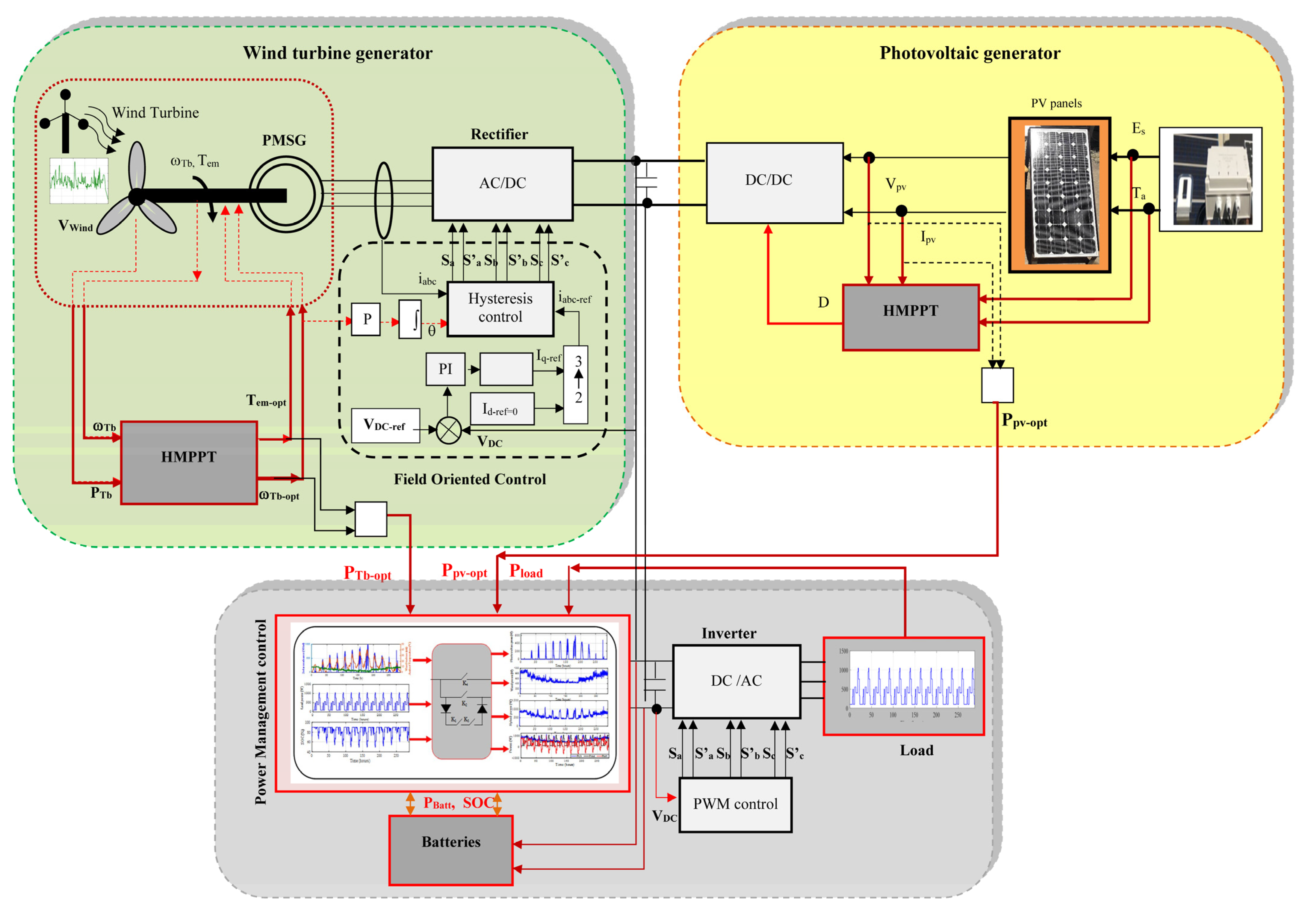
A permanent magnet synchronous generator (PMSG)-equipped wind turbine system, DC/DC and DC/AC photovoltaic converters, storage batteries, solar irradiance sensors and wind speed sensors make up the studied system (Figure 1). The power maximization in each generator is performed using the proposed hybrid MPPT algorithm (HMPPT), and a power flow strategy is used to control the different sources.
The implemented design method is based on the total incident energy’s annual monthly average. Monthly energy of each generator and load demand are calculated to find the different areas of panels and wind turbine [1]. The different areas of the PV and wind turbine generator are given by Equations (1) and (2) [1]:
S pv = max ( E Load , m E pv , m )
  S wind = max ( E Load , m E wind , m )
The PV, wind and load energy produced are given by Equation (3):
E pv = η pv . S pv . E irr
E wind = P wind . Δ t   = ( 1 / 2 ) . ρ . S . V wind 3 . C p
E Load = S pv . E pv + S wind . E wind
with:
η pv = η pv STC . [ 1 β oc . ( T j T j STC ) ]
{ S pv = k perc ( E Load / E pv ) S wind = ( 1 k perc ) ( E Load / E wind )
The monthly energies produced are
{ E pv , m = ( m = 1 12 E pv ) / 12 E wind , m = ( m = 1 12 E wind ) / 12 E Load , m = ( m = 1 12 E Load ) / 12
where kperc is the PV source’s fraction of the load, and (1 − kperc) is the wind source’s fraction of the load.
As a result, it is obtained:
{ S pv = k perc ( E Load , ave / E pv , ave ) S wind = ( 1 k perc ) ( E Load , ave / E wind , ave )
The following equations determine the number of PV panels and wind turbines:
{ S pv , final = N pv . S pv , unit S wind , final = N wind . S wind , unit
The average consumed energy is given by:
E load ave = E pv , ave . S pv , unit + E wind , ave . S wind , unit
In Table 1, various calculations are summarized to demonstrate the different configurations of the solar system’s linkage with the wind power system. It can be observed that the average photovoltaic energy is about 19.80 kWh/day, and the average wind energy is about 134.12 kWh/m2. Since the average load energy required is 476.86 kWh, the combination of 38 solar panels and 0 wind turbines (Table 2) corresponds to the required load energy (486.02 kWh). However, since the studied system is a hybrid system (PV/wind turbine), only the configuration of 8 panels and 1 wind turbine is closest to the required load energy (523.47 kWh).The calculation of battery capacity can be written as [32]:
C Batt = ( d aut . E load , m ) / ( U Batt . PDP . η Batt . N m )
The batteries number can be calculated as
N batt = ENT [ C batt / C batt u ]
with: d aut as the days of autonomy (days), E load , m the monthly load consumed (kWh/day) Nm: 31 days,   U batt as the voltage battery (V), PDP as the depth of discharge, η batt the efficiency battery and C batt u as the chosen battery capacity.
Table 3 summarizes all the number components to be used. Finally, the total maximum power of Photovoltaic panels is Ppv-tot = 3 × 110 = 640 Wp, while the maximum wind turbine power is about 01 × 900 W = 900 W and 02 batteries of (12 V, 100 Ah) are used.

3. Optimization Methods

To optimize the strategy in PV and wind turbine generators, two MPPT approaches (P&O and AFLC) are adopted.

3.1. P&O Method

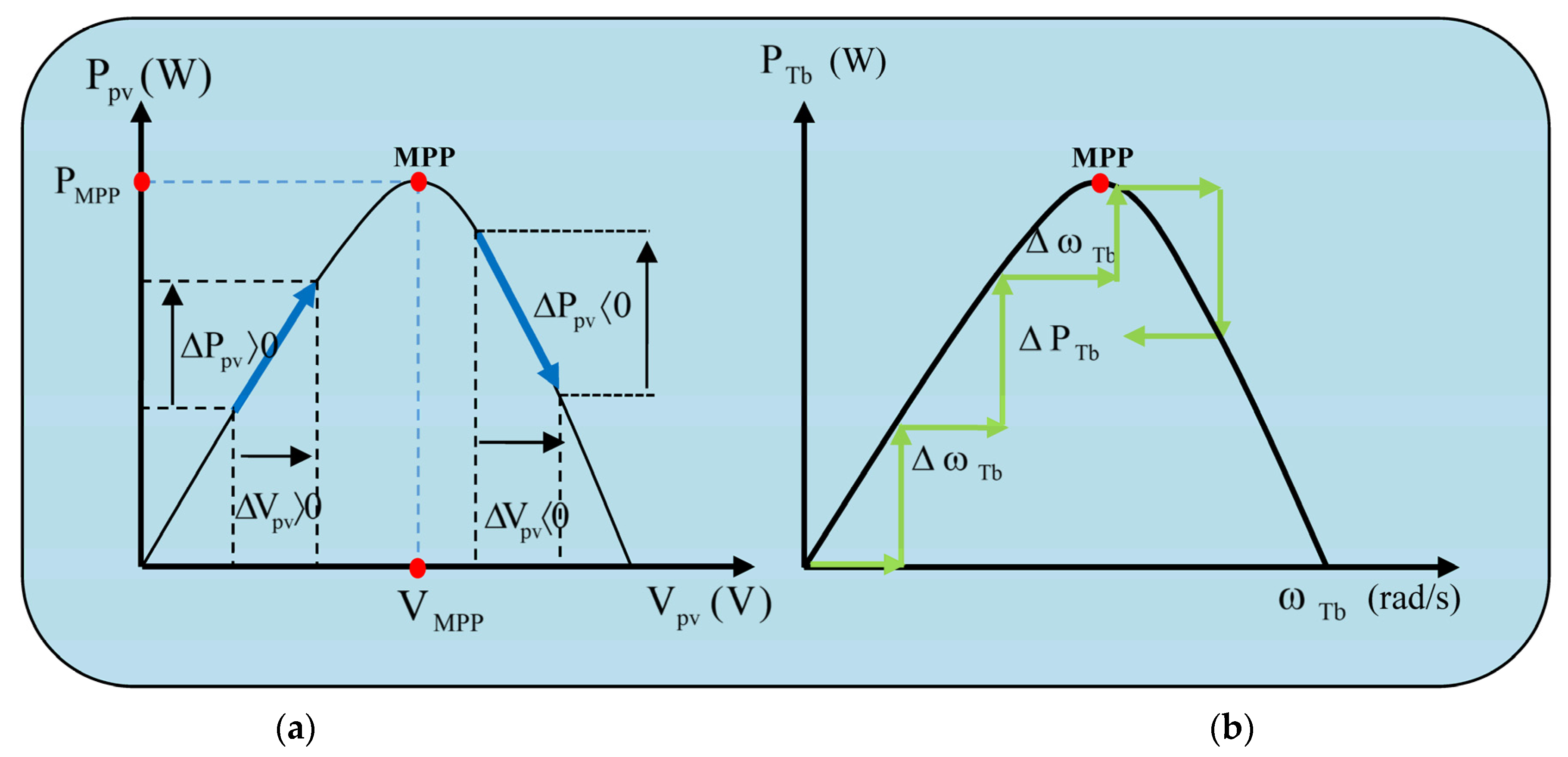
This algorithm principle is described in Figure 2, and explained in the flowchart (Figure 2) [1].

3.2. Adaptative Fuzzy Logic Controller (AFLC)

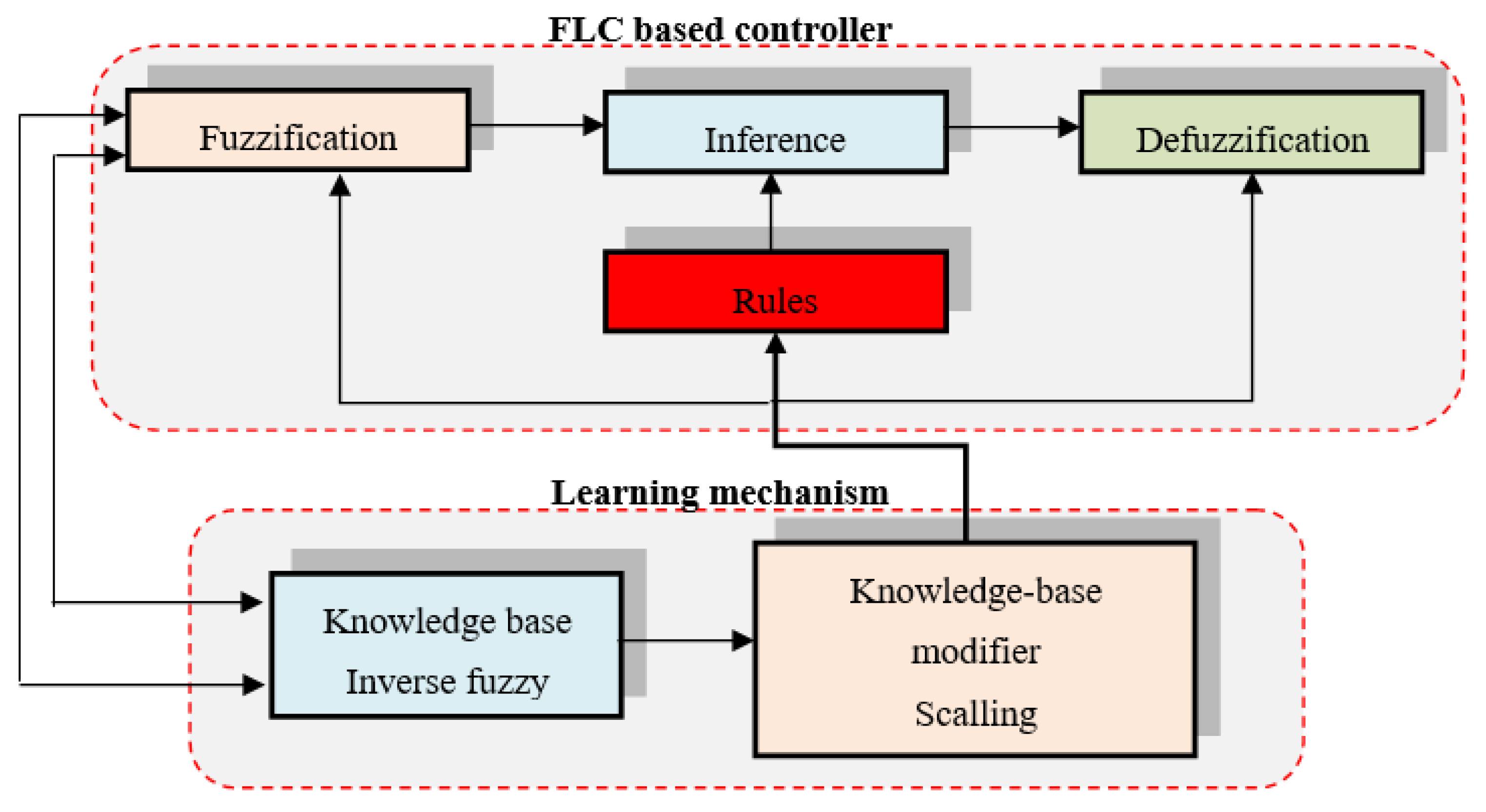
Adaptive Fuzzy Logic Controller (AFLC) is an upgraded version of the Fuzzy Logic Controller (FLC) that includes an adaptive mechanism for tuning the controller parameters in realtime based on changes in the system and environmental parameters (Figure 3). The goal of the AFLC is to improve the performance of the FLC by adjusting its duty-cycle or other control parameters to optimize the system response. The AFLC typically includes two main components: a fuzzy logic controller and a learning mechanism. The fuzzy logic controller is similar to the FLC, and is used to process inputs from sensors and generate control signals. The learning mechanism is responsible for monitoring the system performance and environmental parameters and adjusting the FLC parameters accordingly. In the AFLC, the inputs to the fuzzy logic controller typically include the PV module’s voltage and current, which are added to the preceding values to produce the average value. This input is then processed by the fuzzy logic controller, which generates an output signal that is used to control the system. The learning mechanism is used to modify the FLC duty-cycle or other parameters based on the performance of the system and environmental parameters. This mechanism typically includes a set of rules that are used to adjust the FLC parameters based on feedback from sensors and other sources.The AFLC is a powerful tool for optimizing the performance of renewable energy systems by providing real-time control and adaptation to changes in the system and environmental parameters. By incorporating fuzzy logic control and adaptive learning mechanisms, the AFLC can improve the efficiency, reliability and stability of renewable energy systems.
The controller MAMDANI type is shown in Table 4, along with functions for membership in seven classes [1]. By using linguistic terms to describe the input and output variables, the FLC can make control decisions based on qualitative descriptions rather than precise numerical values.

3.3. Hybrid MPPT Approach

A hybrid MPPT approach is suggested (HMPPT). This is a combinationof P&O and AFLC methods. First, the optimal values are calculated (Equation (14)), and then the proposed algorithm gives the chosen best power values (Equation (15)).
{ P PV opt = { P PV P & o , P PV AFLC } P Tb opt = { P Tb P & o , P Tb AFLC }
{ P PV best = max ( P PV opt ) P Tb best = max ( P Tb opt )
where: P PV opt and P Tb opt are the different PV and wind turbine power values of each MPPT method (P&o and AFLC),respectively, and P PV best and P Tb best are the selected best optimal PV and wind turbine power chosen by the HMPPT algorithm, respectively.
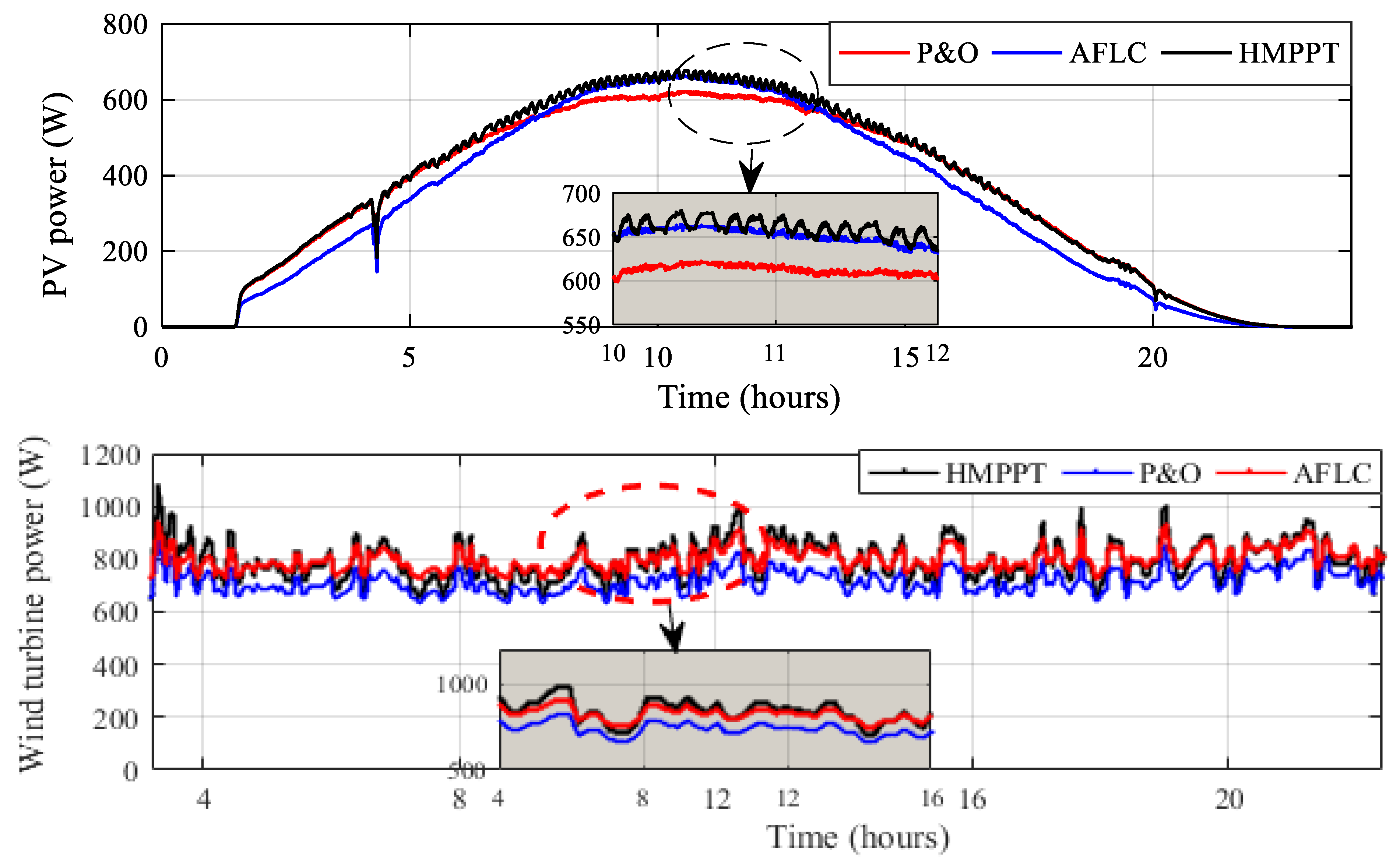
An application ismade during a whole day to show the performance of the HMPPT method (Figure 4).
The three MPPT methods (P&O, AFLC and HMPPT) have been applied. It is evident from Figure 4 that the suggested HMMPT approach reacts more quickly than the P&O and AFLC methods.

4. Simulation Study

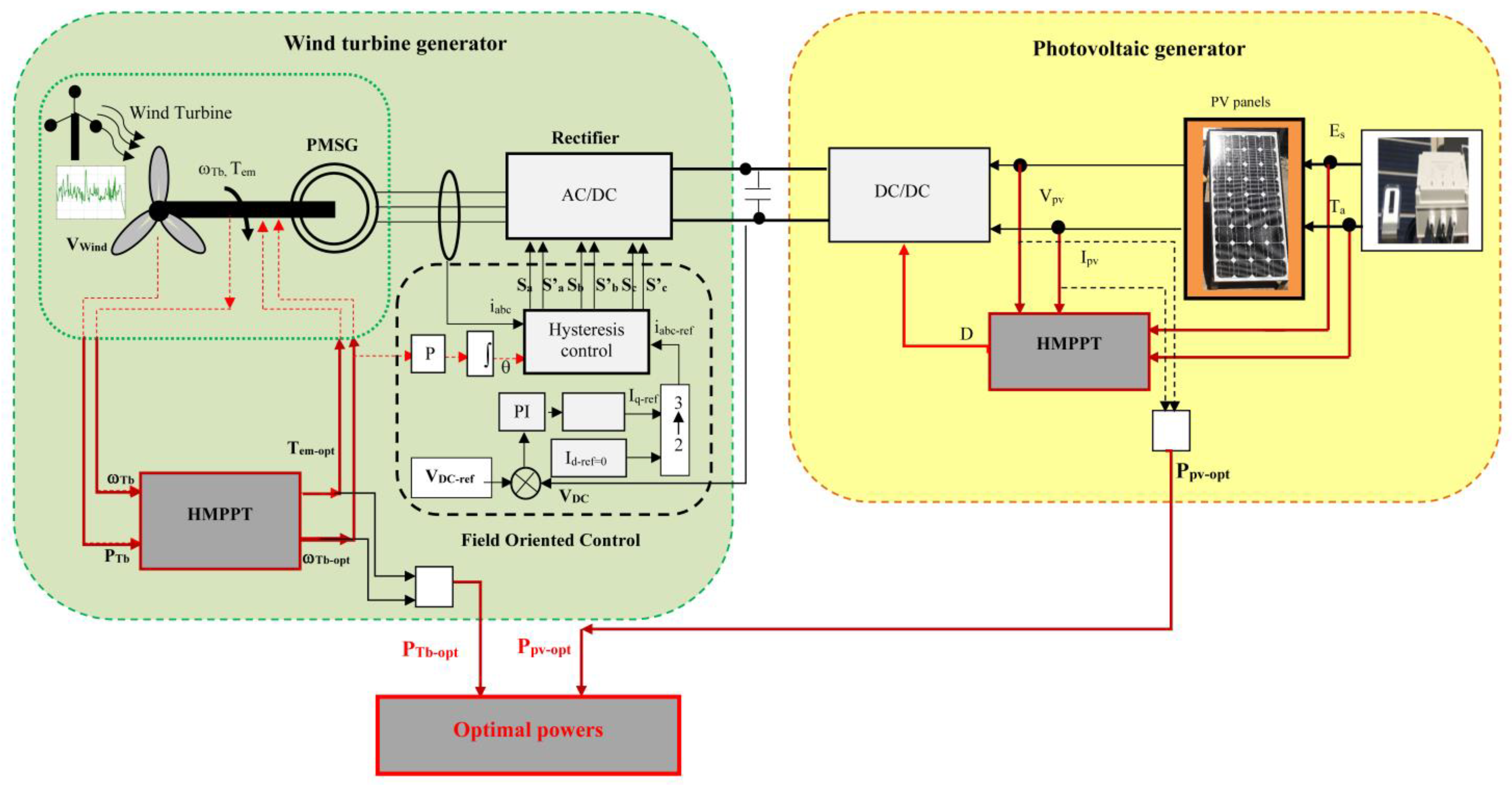
The power of each generator is maximized using the proposed HMPPT strategy (Figure 5).The hybrid HMPPT MPPT approach is a combination of the P&O and AFLC methods.
In a wind turbine generator, field-oriented control (FOC) is used for DC bus regulation to keep constant the voltage DC bus constant whatever the wind speed variations. This is used to control the currents and voltages of the stator windings of the generator, which are then converted to DC voltage by a rectifier and fed into the DC bus.

4.1. Measurements ofSolar Irradiation, Temperature and Wind Speed Profiles

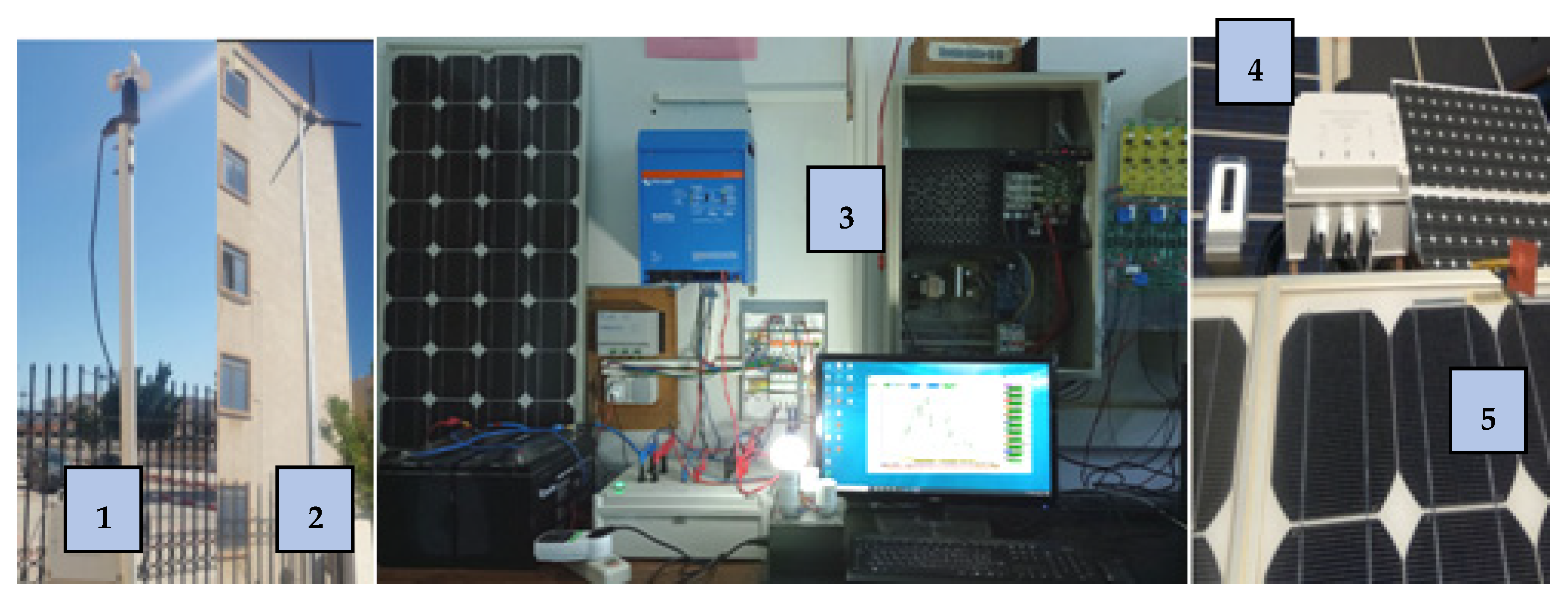
A measurement acquisition equipment was used in the lab to detect the sun radiation, temperature and wind speed (Figure 6). It is essentially composed of sensors in order to transfer the different signals to a data processing interface, and then to a PC where they will be displayed using ACQUIsol software in realtime.

4.2. Simulation under Measured Profiles of Solar Irradiation, Temperature and Wind Speed

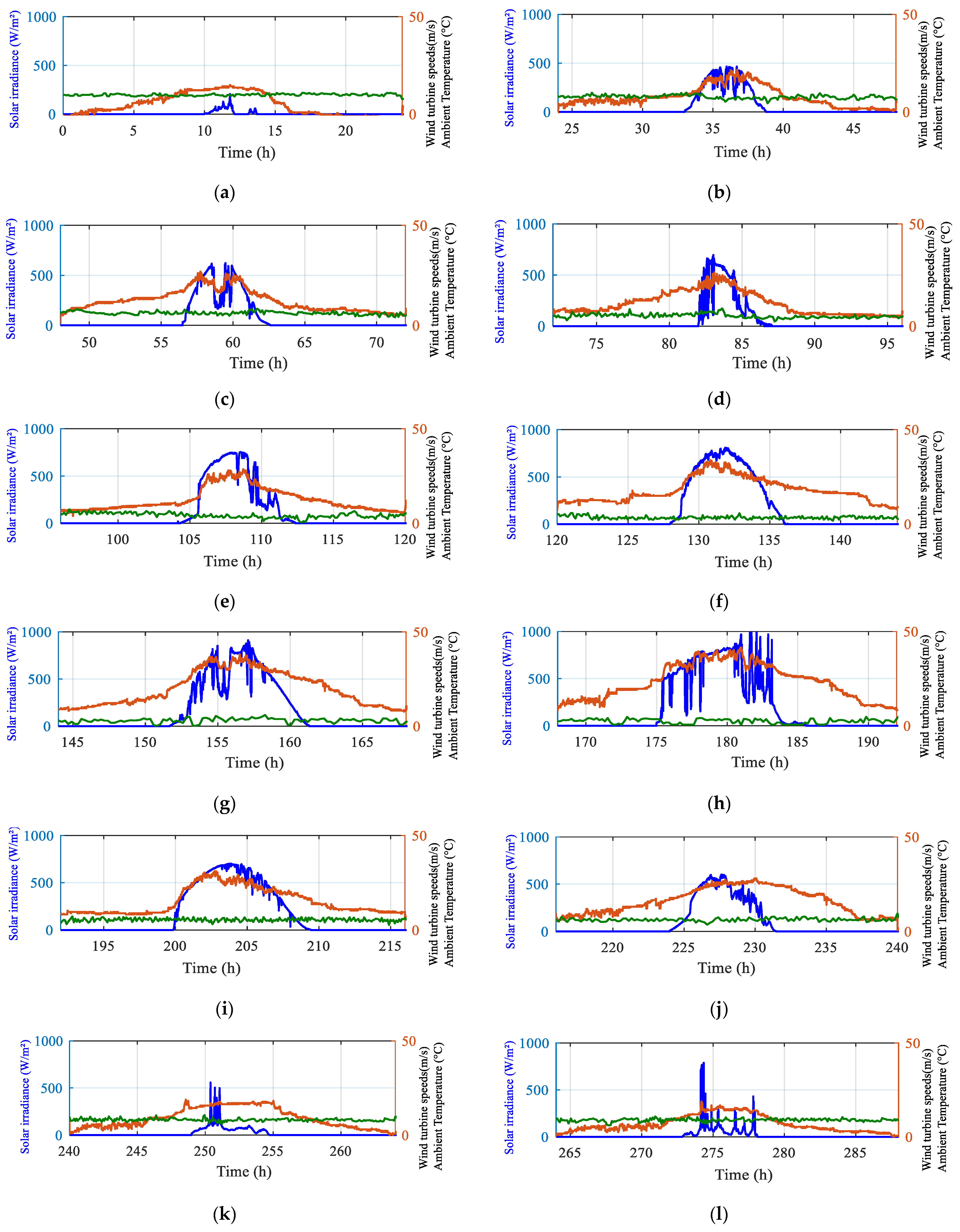
Matlab/Simulink is used to run the simulations, which consider the measured solar irradiance and wind speeds profile for each day (Figure 7).
The chosen load profile is as shown in Figure 8. In our work, we use a hybrid HMPPT. The power obtained from the PV generator under the three MPPTs is shown in Figure 9. Three zoomed-in views of the photovoltaic power during three different profile days are displayed in Figure 9a–c, corresponding respectively to medium, low and high solar irradiance.
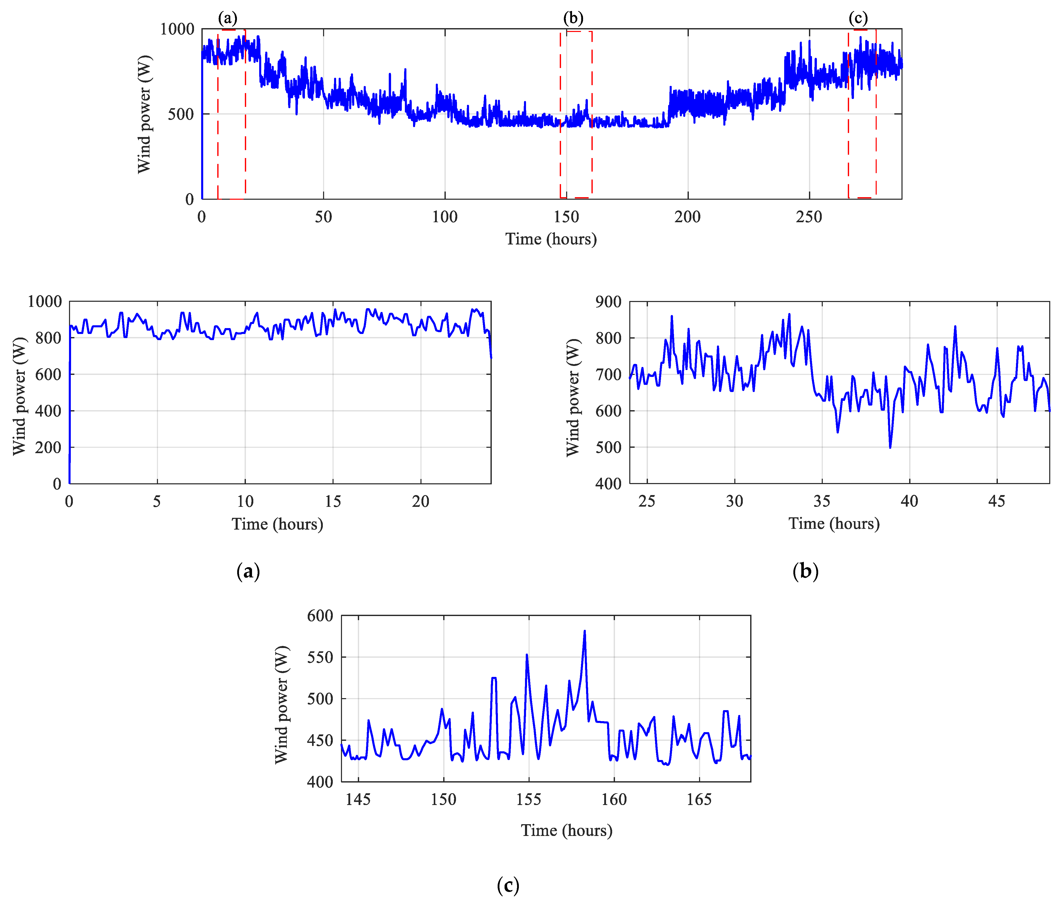
The wind power obtained using the HMPPT strategy is presented in Figure 10. Three zoomed-in views of the wind turbine power during three different profile days are displayed in Figure 10a–c, corresponding respectively to high, medium, and low wind speed velocity.
The renewable power is defined as shown in Figure 11. Three zoomed-in views of the renewable power during three different profile days are presented in Figure 11a–c, corresponding respectively to medium, low and high solar irradiance and wind speed velocity.
P R e n e w = P p v + P w i n d
It can be said that when using the hybrid method HMPPT and for each energy source, significant power improvements can be realized when compared to using a single MPPT technique. The required power by the batteries is reduced, as shown in Figure 12. Three zoomed-in views of the battery power during three different profile days are displayed in Figure 12a–c.
The battery state of charge (SOC) is a critical parameter that must be evaluated to ensure safe charging and discharging procedures. Estimating the SOC helps to protect the battery from overcharging or deep discharging, thereby extending its life. The battery SOC is maintained within the following limits
SOC min   SOC SOC max  
where SOCmax is the maximum SOC value and SOCmin is the minimum SOC value.
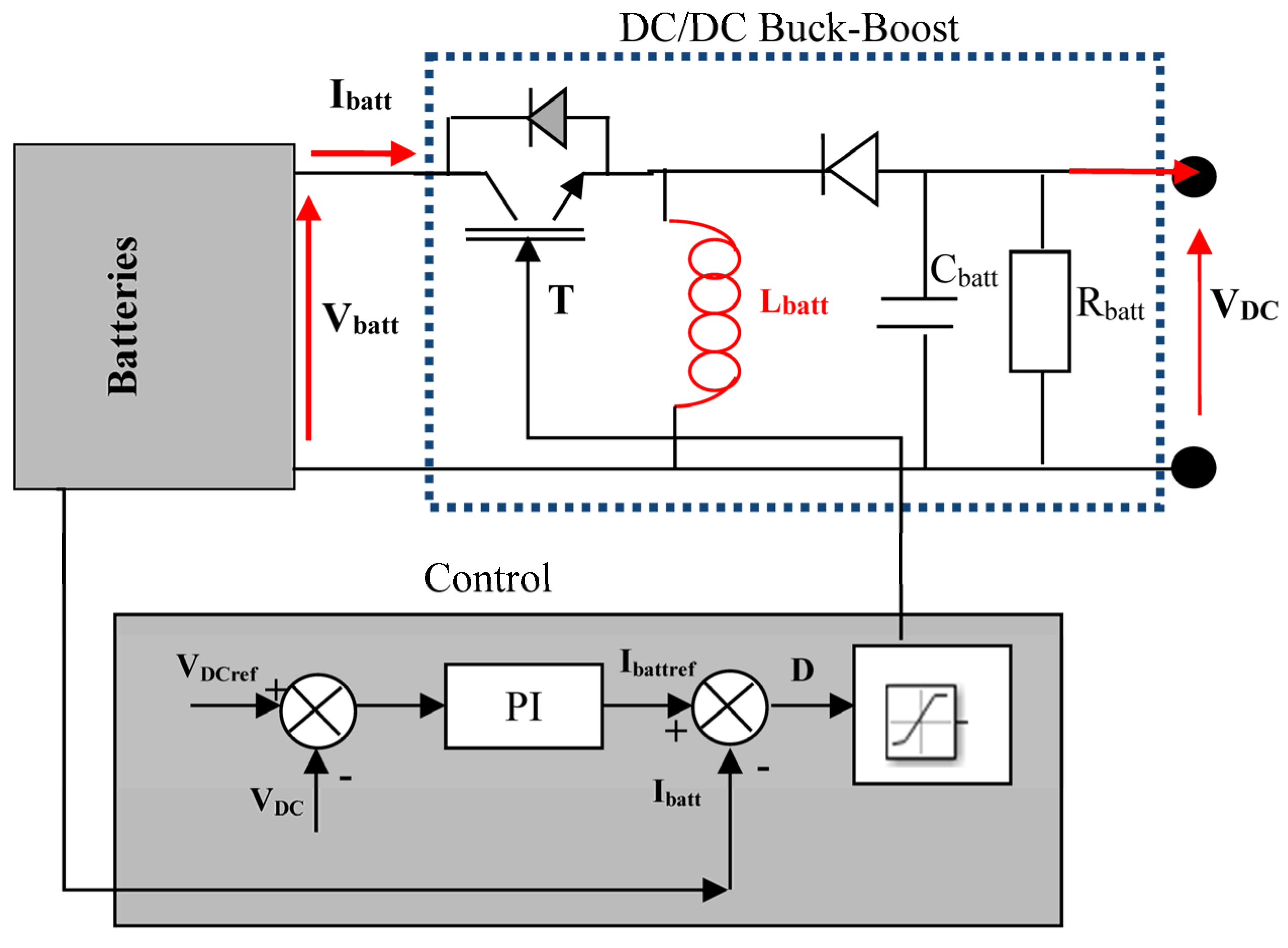
For battery control, we usually use a Buck-Boost converter for the charging and discharging process (Figure 13).
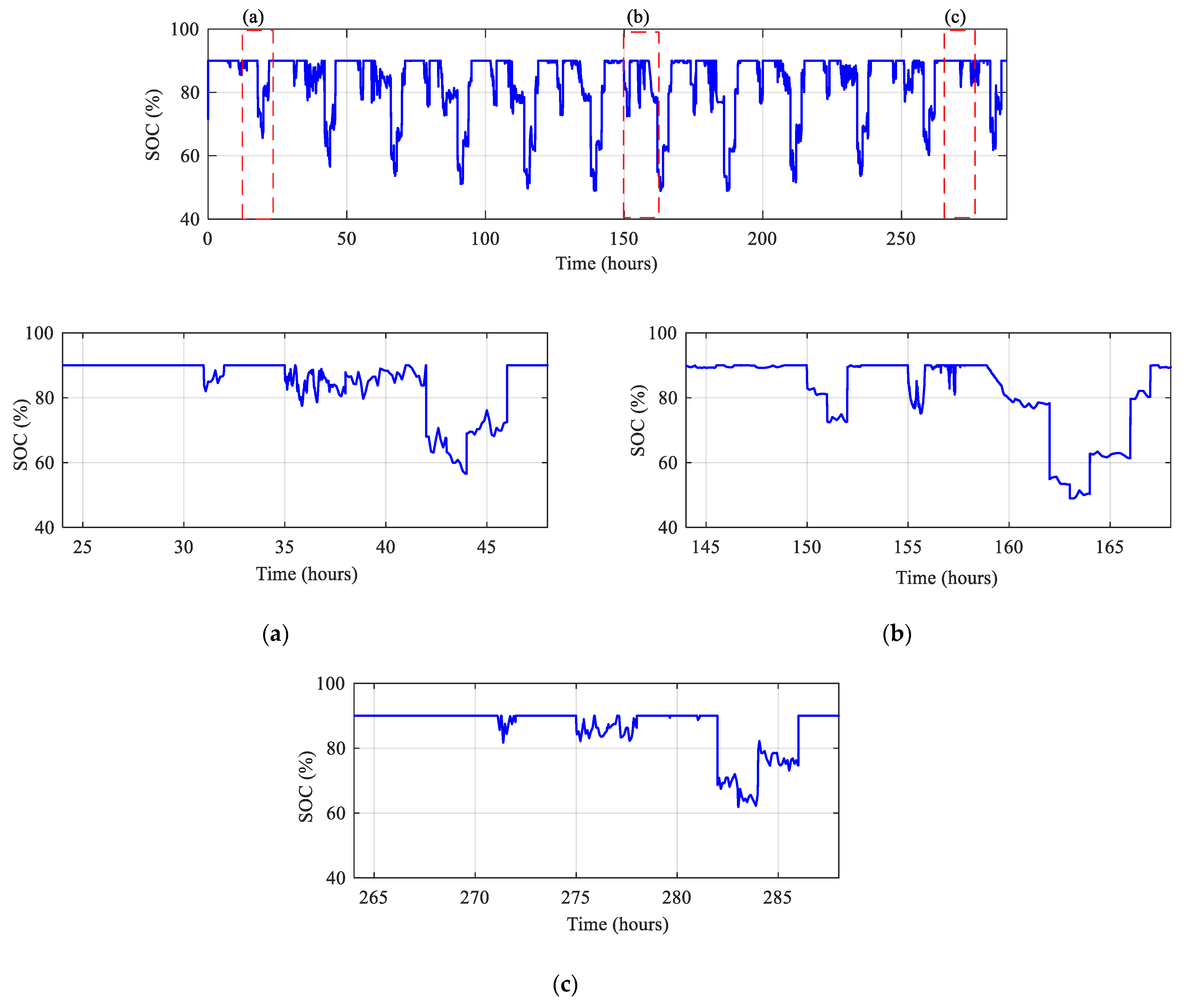
In our case, the SOC was controlled between 30% and 90% (Figure 14). Three zooms of the SOC during three different profile days, respectively, are shown in Figure 14a–c, corresponding respectively to medium, low and high solar irradiance and wind speed velocity It is noticed that the SOC in maintaining between the SOCmin and the SOCmax whatever the variations of solar irradiance and wind speed during the three different profile days. It is maintained to its maximum value of 90 percent whatever the day profile with some variations to reach a SOCmin of 56.57% in the first day (Figure 14a), 48.98% in the second day (Figure 14b) and 61.98 % in the third day. The batteries are less stressed and discharge less, which is very important for their life span.
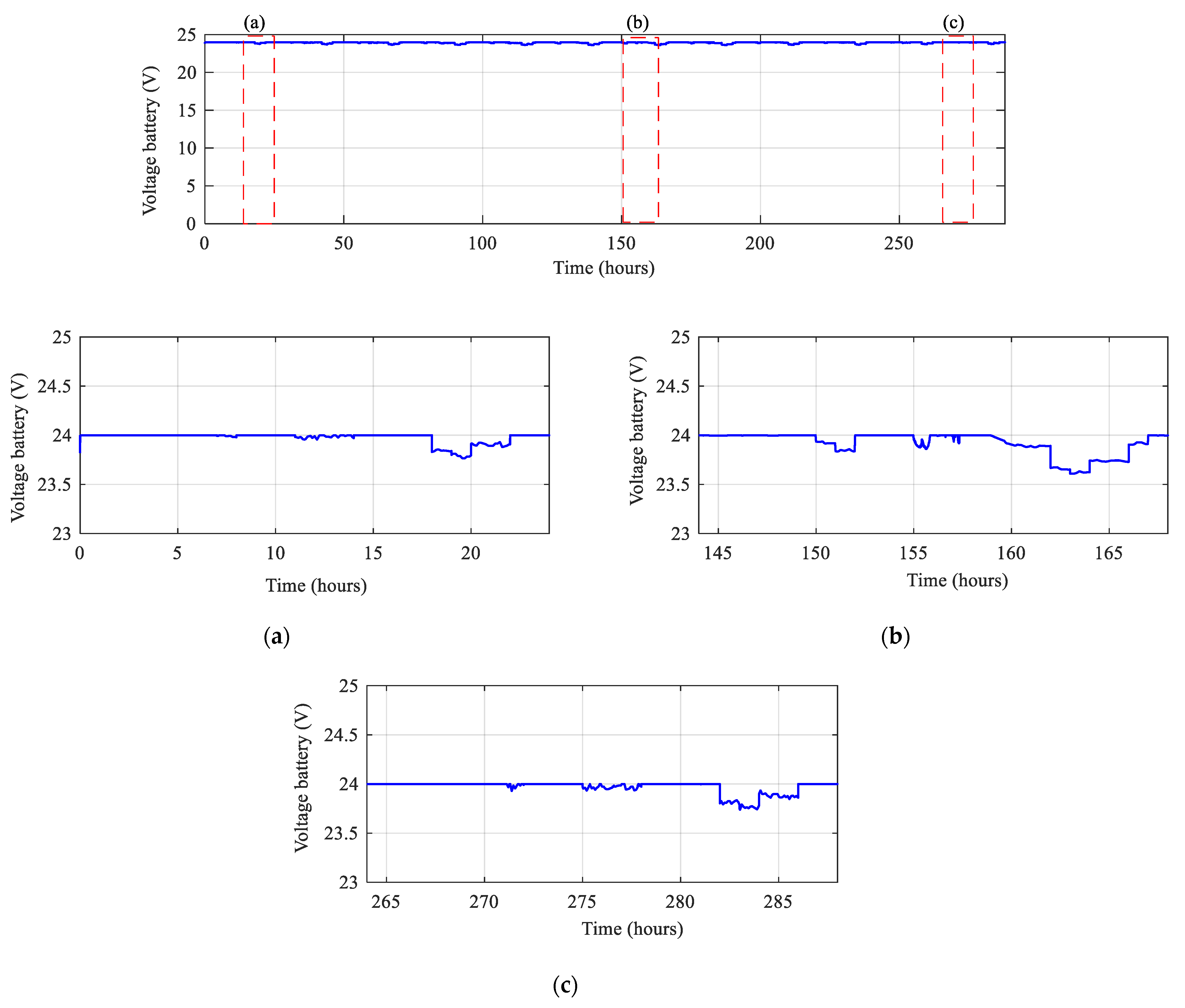
It can be said that on any given day, with its own weather variables, the suggested hybrid technique produces the best SOC results. In comparison to the other methods, it maintains its maximum value of 90 percent. With the proposed hybrid method, the batteries are less stressed and discharge less, which is very important for their lifespan. Furthermore, it is noted in Figure 15 that the battery voltage stays close to the reference voltage of 24V, which is likely the desired voltage for the system. The hybrid MPPT approach (HMPPT) produces the best values in terms of battery voltage, whatever the day chosen. This one quickly reaches its value of 24V and is kept longer compared to the other methods. Three zoomed-in views of the voltage battery during three different profile days, respectively, are shown in Figure 15a–c.
The battery voltage is maintained to its maximum value of 24V whatever the day profile with some variations to decrease to 23.77 V in the first day (Figure 15a), 23.61 V in the second day (Figure 14b) and 23.75 V in the third day. The batteries have not discharged too much, which is very important for their life span.
The findings suggest that the HMPPT approach is effective at optimizing the power output of the renewable energy source and regulating the battery voltage to ensure the safe and optimal operation of the system.

5. Power Control of the Studied System

5.1. Literature Review on Energy Management Control

Energy management control (EMC) is a crucial component in multi-source renewable energy systems (MSRES). Its applications range from renewable energy sources such as PV and wind, with their simple or multi-storage systems, to automotive traction using batteries, fuel cells (FC) and supercapacitors (SC). Numerous research articles [40,41,42,43,44,45,46,47,48,49,50,51,52,53,54,55,56,57,58,59,60,61,62,63,64,65] have investigated various control strategies for these systems, as outlined in Table 5. While the technologies used in each study differ, most applications focus on isolated systems for electrification [40,45,46,47,48,49,50,51], microgrids [42,58,60,62,63,64] and multi-storage in traction and electric vehicles [47,50,52]. In most works, optimal component sizing has been studied [3,4,5,6,7,8,9,10,11,12,13], and it has been concluded that efficient control management strategies are necessary for correctly sizing the different components of MSRES. Some of these strategies are based on linear controllers [51,52,53], while others employ more intelligent methods [47,60,61,62,63,64,65]. Most of the works focus on simulation, implementation, economic study, optimization and analysis of the system’s performance and environmental impact. The mainfocus of EMC methods is controlling the power from different sources to supply the load and protect the storage system. Some EMC methods use “if-else” statements in the decision algorithms [56], while others employ more intelligent and predictive methods [60,61,62,63,64,65,66,67,68,69,70,71]. The following table provides a summary of the literature review of the systems studied.

5.2. Control of the Studied System

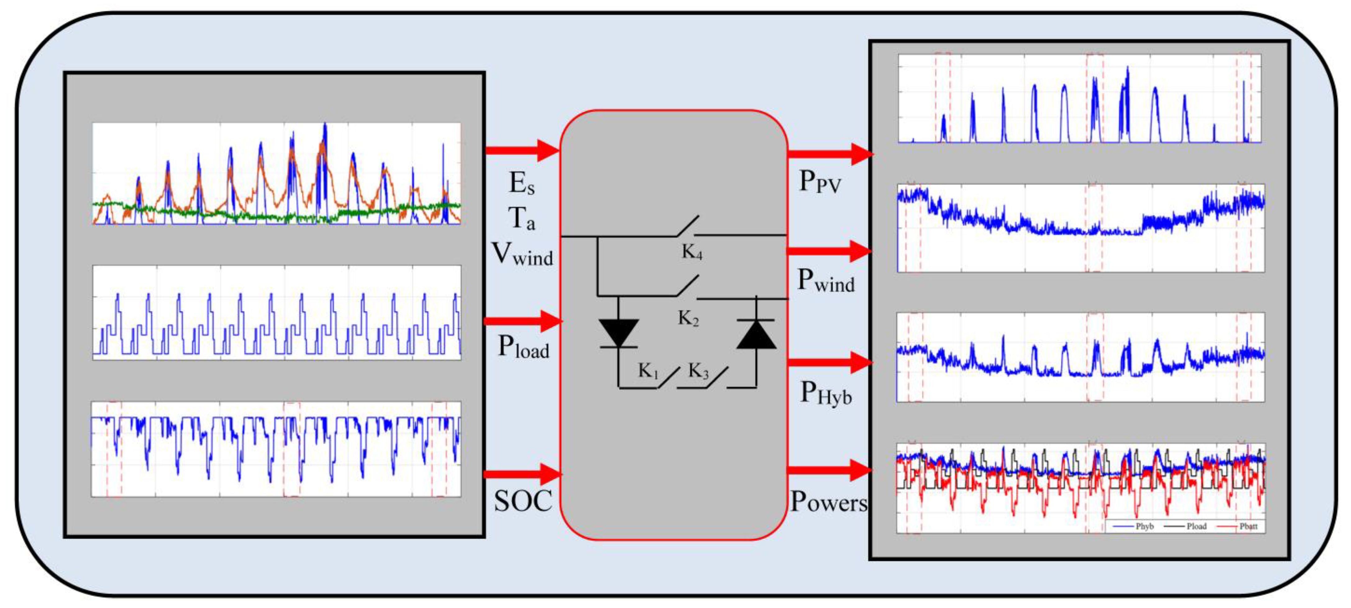
The studied system PV/Wind turbine with batteries with the HMPPT strategy has been controlled using a proposed power management control (Figure 16). There is always a comparison between load power and hybrid renewable power. When there is a lack of power, the batteries, if fully charged, can supply the load alone or in compensation with other sources; it also charges batteries if there is an excess of power. For this, four switches are used in the suggested power flow system (Figure 17).
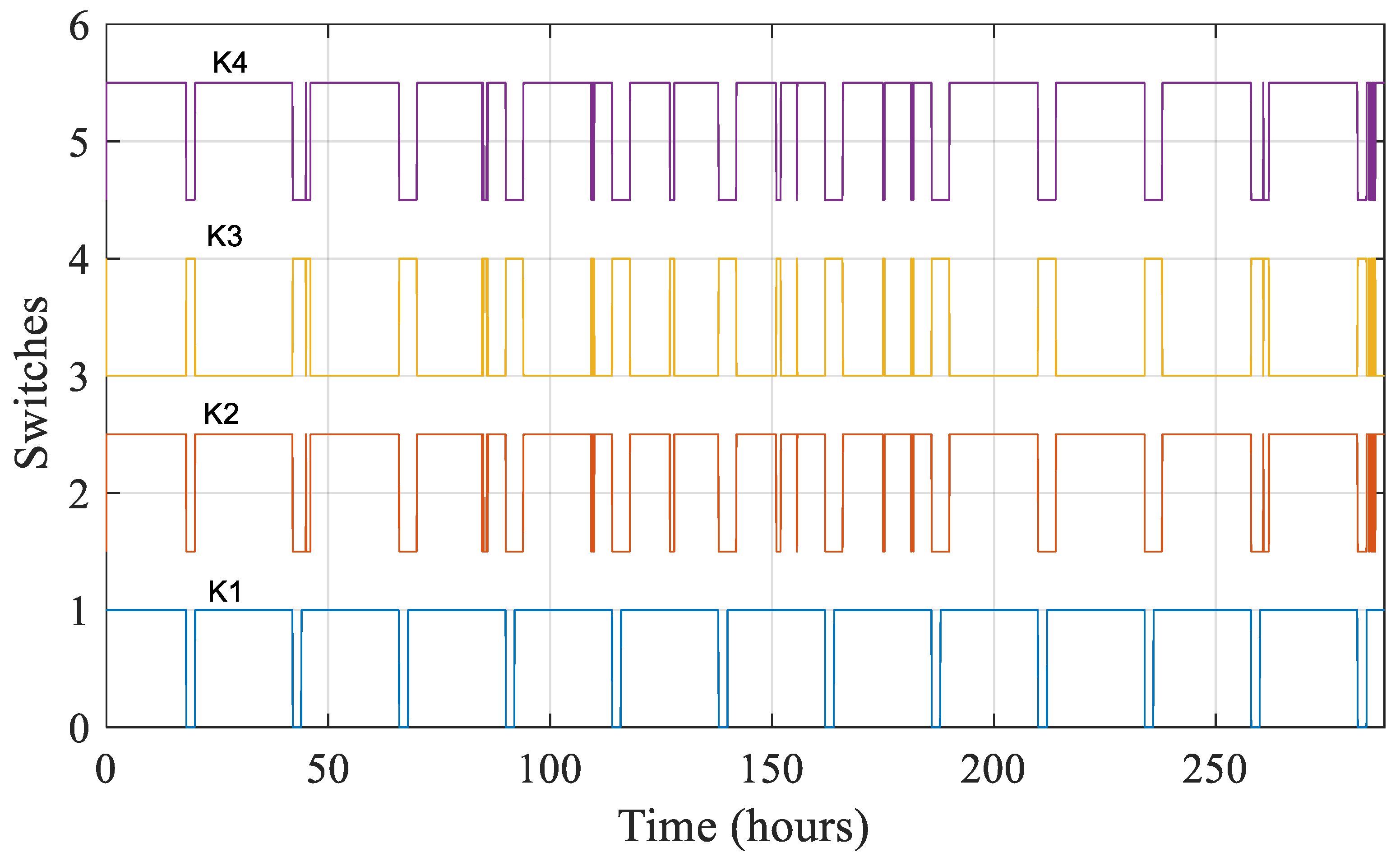
The system uses four switches (K1, K2, K3, K4) to control the flow of power between the different sources and the load. When there is sufficient power from the renewable sources to meet the load demand, switch K1 is closed to allow the power to flow directly to the load. At the same time, switch K4 is closed to allow any excess power to be stored in the batteries. If the renewable sources are not producing enough power to meet the load demand, switch K1 is opened and switch K2 is closed to allow the batteries to supply power to the load. The batteries can either supply power alone or in conjunction with any remaining power from the renewable sources. If the batteries become depleted, switch K3 is closed to allow an alternate power source, such as a generator or grid power, to supply power to the load. At the same time, switch K4 is closed to allow the batteries to be charged from the alternate power source. The different switches operate as shown in (Table 6).
The load profile depends on PV, wind and battery powers:
P Load =   P PV + P wind ± P Batt .
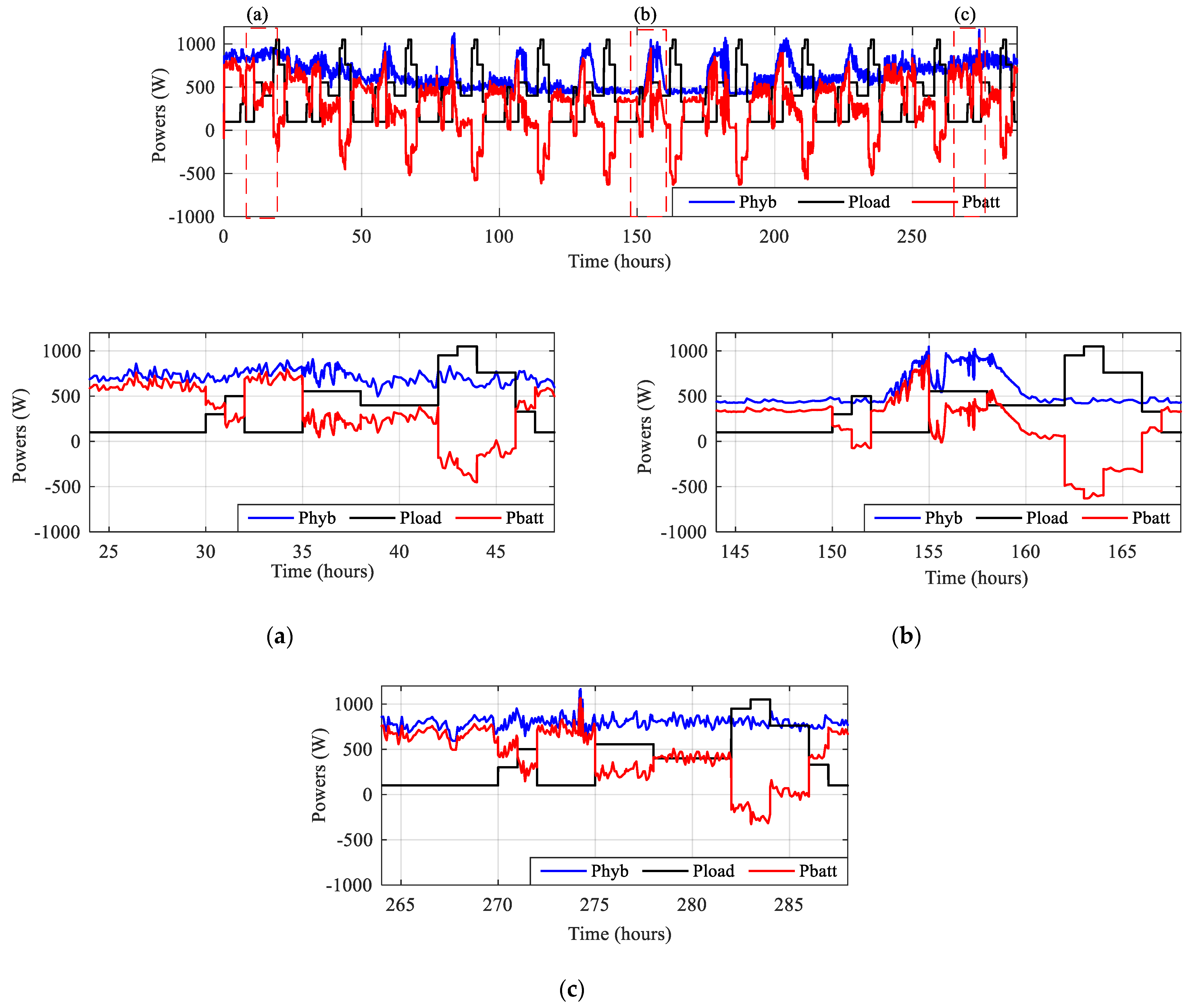
Figure 18 shows the various switch signals, while Figure 19 depicts the various powers. It can be concluded that the load power was satisfied during the twelve typical days throughout the year due to good sizing and the effective management of the different power sources, in accordance with the power balance equation.
The batteries’ capacity was used up to 44.93%on the first day (Figure 19a), 62.96% on the second (Figure 19b), and only 32.36% on the third (Figure 19c). As expected, the power discharge represented only a small quantity (indicated by the negative parts in a red color) when compared to the results obtained using the proposed hybrid method, which placed less stress on the battery.

6. Conclusions

The paper presents the optimal control of a hybrid photovoltaic/wind turbine/battery system, and analyzes and compares the results from different findings. There was a significant improvement in power for each energy source when using the hybrid HMPPT method, as compared to using a single MPPT technique. The required power from the batteries has been greatly reduced. The main contribution of this paper is the reduction of stress on the storage batteries in a multi-source system through the combination of an accurate sizing approach and a hybrid MPPT algorithm with a power flow method. The results demonstrate that the different energy sources were managed optimally to meet the load demand, even under varying weather conditions. The findings confirm the effectiveness and viability of the suggested control method for the entire year.

Author Contributions

Conceptualization, D.R and T.R.; methodology, D.R.; software, D.R.; validation, D.R., A.E and S.M.; formal analysis, S.M.; investigation, D.R.; resources, T.R.; data curation, D.R.; writing—original draft preparation, S.M; writing—review and editing, S.M.; visualization, A.E.; supervision, T.R.; project administration. All authors have read and agreed to the published version of the manuscript.

Funding

This research received no external funding.

Data Availability Statement

Not applicable.

Conflicts of Interest

The authors declare no conflict of interest.

References

  1. Rekioua, D.; Matagne, E. Optimization of Photovoltaic Power Systems: Modelization, Simulation and Control; Series: Green Energy and Technology; Springer: Berlin/Heidelberg, Germany, 2012. [Google Scholar]
  2. Silva, A.R.; Estanqueiro, A. From Wind to Hybrid: A Contribution to the Optimal Design of Utility-Scale Hybrid Power Plants. Energies 2022, 15, 2560. [Google Scholar] [CrossRef]
  3. Chen, S.; Zhang, Y.; Zheng, J. Assessment on Global Urban Photovoltaic Carrying Capacity and Adjustment of Photovoltaic Spatial Planning. Sustainability 2021, 13, 3149. [Google Scholar] [CrossRef]
  4. Chomać-Pierzecka, E.; Kokiel, A.; Rogozińska-Mitrut, J.; Sobczak, A.; Soboń, D.; Stasiak, J. Analysis and Evaluation of the Photovoltaic Market in Poland and the Baltic States. Energies 2022, 15, 669. [Google Scholar] [CrossRef]
  5. Xiao, W.; Elnosh, A.; Khadkikar, V.; Zeineldin, H. Overview of maximum power point tracking technologies for photovoltaic power systems. In Proceedings of the IECON 2011-37th Annual Conference of the IEEE Industrial Electronics Society 2011, Melbourne, Australia, 7–10 November 2011; pp. 3900–3905. [Google Scholar]
  6. Kordestani, M.; Mirzaee, A.; Safavi, A.A.; Saif, M. Maximum Power Point Tracker (MPPT) for Photovoltaic Power Systems-A Systematic Literature Review. In Proceedings of the European Control Conference (ECC) 2018, Limassol, Cyprus, 12–15 June 2018; pp. 40–45. [Google Scholar]
  7. Salas, V.; Olias, E.; Barrado, A.; Lazaro, A. Review of the maximum power point tracking algorithms for stand-alone photovoltaic systems. Sol. Energy Mater. Sol. Cells 2006, 90, 1555–1578. [Google Scholar] [CrossRef]
  8. Zainuri MA, A.M.; Radzi MA, M.; Soh, A.C.; Rahim, N.A. Development of adaptive perturb and observe-fuzzy control maximum power point tracking for photovoltaic boost dc–dc converter. IET Renew. Power Gener. 2014, 8, 183–194. [Google Scholar] [CrossRef]
  9. Radhia, G.; Mouna, B.H.; Lassaad, S.; Barambones, O. MPPT controller for a photovoltaic power system based on increment conductance approach. In Proceedings of the 2013 International Conference on Renewable Energy Research and Applications (ICRERA) 2013, Madrid, Spain, 20–23 October 2013; pp. 73–78. [Google Scholar]
  10. Khadidja, S.; Mountassar, M.; M’hamed, B. Comparative study of incremental conductance and perturb & observe MPPT methods for photovoltaic system. In Proceedings of the 2017 International Conference on Green Energy Conversion Systems (GECS) 2017, Hammamet, Tunisia, 23–25 March 2017; pp. 1–6. [Google Scholar]
  11. Achour, A.; Rekioua, D.; Mohammedi, A.; Mokrani, Z.; Rekioua, T.; Bacha, S. Application of direct torque control to a photovoltaic pumping system with sliding-mode control optimization. Electr. Power Compon. Syst. 2016, 44, 172–184. [Google Scholar] [CrossRef]
  12. Sun, L.; Zhengdandan Han, F. Study on MPPT approach in photovoltaic system based on fuzzy control. In Proceedings of the 2013 IEEE 8th Conference on Industrial Electronics and Applications (ICIEA) 2013, Melbourne, Australia, 19–21 June 2013; pp. 1259–1263. [Google Scholar]
  13. Masoum, M.A.S.; Dehbonei, H. Design, construction and testing of a voltage-based maximum power point tracker (VMPPT) for small satellite power supply. In Proceedings of the 13th Annual AIAA/USU Conference, Small Satellite 1999, Logan, UT, USA, 23–26 August 1999. [Google Scholar]
  14. Noguchi, T.; Togashi, S.; Nakamoto, R. Short-current pulse-based adaptive maximum power point tracking for a photovoltaic power generation system. In Proceedings of the 2000 IEEE International Symposium on ISIE 2000, Cholula, Mexico, 4–8 December 2000; Volume 1, pp. 157–162. [Google Scholar]
  15. Esram, K.; Chapman, P.L. Comparison of Photovoltaic Array Maximum Power Point Tracking Techniques. IEEE Trans. Energy Convers. 2007, 22, 439–449. [Google Scholar] [CrossRef] [Green Version]
  16. Hohm, D.P.; Ropp, M.E. Comparative Study of Maximum Power Point Tracking Algorithms. Prog. Photovolt. Res. Appl. 2003, 11, 47–62. [Google Scholar] [CrossRef]
  17. Santos LJ, L.; Antunes, F.; Chehab, A.; Cruz, C. A Maximum Power Point Tracker for PV Systems Using a High Performance Boost Converter. Sol. Energy 2006, 80, 772–778. [Google Scholar] [CrossRef]
  18. Krauter Stefan, C.W. Solar Electric Power Generation—Photovoltaic Energy Systems; Springer: Berlin/Heidelberg, Germany, 2006. [Google Scholar]
  19. Liu, F.; Duan, S.; Liu, F.; Liu, B.; Kang, Y. A Variable Step Size INC MPPT Method for PV Systems. IEEE Trans. Ind. Electron. 2008, 55, 2622–2628. [Google Scholar]
  20. Noman Abdullah, M.; Addoweesh Khaled, E.; Mashaly Hussein, M. DSPACE Real-Time Implementation of MPPT-Based FLC Method. Int. J. Photoenergy 2013, 2013, 549273. [Google Scholar]
  21. Mondal, A.; Yuvarajan, S. MPPT Scheme for Small Scale Photovoltaic Systems Using dSPACE. In Proceedings of the 2012 IEEE Green Technologies Conference, Tulsa, OK, USA, 19–20 April 2012; pp. 1–3. [Google Scholar]
  22. Sudhakar Babu, T.; Rajasekar, N.; Sangeetha, K. Modified Particle Swarm Optimization technique based Maximum Power Point Tracking for uniform and under partial shading condition. Appl. Soft Comput. 2015, 34, 613–624. [Google Scholar] [CrossRef]
  23. Khare, A.; Rangnekar, S. A review of particle swarm optimization and its applications in Solar Photovoltaic system. Appl. Soft Comput. 2013, 13, 2997–3006. [Google Scholar] [CrossRef]
  24. Mayssa, F.; Sbita, L. Advanced ANFIS-MPPT control algorithm for sunshine photovoltaic pumping systems. In Proceedings of the 1st International Conference Renewable Energies and Vehicular Technology 2012, Nabeul, Tunisia, 26–28 March 2012; pp. 167–172. [Google Scholar]
  25. Rekioua, D. MPPT Methods in Hybrid Renewable Energy Systems. Green Energy Technol. 2020, 79–138. [Google Scholar] [CrossRef]
  26. Linus, R.M.; Damodharan, P. Maximum power point tracking and grid feeding of permanent magnet synchronous generator based wind energy conversion system using modified hill climb searching algorithm. In Proceedings of the India International Conference on Power Electronics, IICPE 2012, Delhi, India, 6–8 December 2012; p. 6450491. [Google Scholar]
  27. Mousa, H.H.H.; Youssef, A.-R.; Mohamed, E.E.M. State of the art perturb and observe MPPT algorithms based wind energy conversion systems: A technology review. Int. J. Electr. Power Energy Syst. 2021, 126, 106598. [Google Scholar] [CrossRef]
  28. Cui, Z.; Song, L.; Li, S. Maximum power point tracking strategy for a new wind power system and its design details. IEEE Trans. Energy Convers. 2017, 32, 1063–1071. [Google Scholar] [CrossRef]
  29. Kumar, D.; Chatterjee, K. A review of conventional and advanced MPPT algorithms for wind energy systems. Renew. Sustain. Energy Rev. 2016, 55, 957–970. [Google Scholar] [CrossRef]
  30. Pande, J.; Nasikkar, P.; Kotecha, K.; Varadarajan, V. A review of maximum power point tracking algorithms for wind energy conversion systems. J. Mar. Sci. Eng. 2021, 9, 1187. [Google Scholar] [CrossRef]
  31. Abdullah, M.A.; Yatim, A.H.M.; Tan, C.W.; Saidur, R. A review of maximum power point tracking algorithms for wind energy systems. Renew. Sustain. Energy Rev. 2012, 16, 3220–3227. [Google Scholar] [CrossRef]
  32. Moon, S.H.; Park, B.G.; Kim, J.W.; Kim, J.M. Maximum Power-Point Tracking Control Using Perturb and Observe Algorithm for Tidal Current Generation System. Int. J. Precis. Eng. Manuf. Green Technol. 2020, 7, 849–858. [Google Scholar] [CrossRef]
  33. Mishra, S.; Shukla, S.; Verma, N.; Ritu, R. Comprehensive review on Maximum Power Point Tracking techniques: Wind Energy. In Proceedings of the International Conference Communication, Control and Intelligent Systems, CCIS 2015, Mathura, India, 7–8 November 2015; pp. 464–469. [Google Scholar]
  34. Rekioua, D.; Rekioua, T.; Soufi, Y. Control of a grid-connected photovoltaic system. In Proceedings of the 2015 International Conference on Renewable Energy Research and Applications, ICRERA 2015, Palermo, Italy, 22–25 November 2015; pp. 1382–1387. [Google Scholar]
  35. Bekiroglu, E.; Yazar, M.D. MPPT Control of Grid Connected DFIG at Variable Wind Speed. Energies 2022, 5, 3146. [Google Scholar] [CrossRef]
  36. Belaid, S.; Rekioua, D.; Oubelaid, A.; Ziane, D.; Rekioua, T. Proposed Hybrid Power Optimization for Wind Turbine/Battery System. Period. Polytech. Electr. Eng. Comput. Sci. 2022, 66, 60–71. [Google Scholar] [CrossRef]
  37. Soliman, M.A.; Hasanien, H.; Azazi, H.Z.; El-kholy, E.E.; Mahmoud, S.A. An adaptive fuzzy logic control strategy for performance enhancement of a grid-connected PMSG-based wind turbine. IEEE Trans. Ind. Inform. 2018, 15, 3163–3173. [Google Scholar] [CrossRef]
  38. Khan, M.J.; Mathew, L.; Alotaibi, M.A.; Malik, H.; Nassar, M.E. Fuzzy-Logic-Based, Comparative Analysis of Different Maximum Power Point Tracking Controllers for Hybrid Renewal Energy Systems. Mathematics 2022, 10, 529. [Google Scholar] [CrossRef]
  39. Elbeji, O.; Hannachi, M.; Benhamed, M. Artificial neural network-based sensorless control of wind energy conversion system driving a permanent magnet synchronous generator. Wind. Eng. 2021, 45, 459–476. [Google Scholar] [CrossRef]
  40. Rodolfo, D.; Jose, L. Efficient design of hybrid renewable energy systems using evolutionary algorithms. Energy Convers. Manag. 2009, 3, 479–489. [Google Scholar]
  41. Lu, D.; Fakham, H.; Zhou, T.; Francois, B. Application of Petri nets for the energy management of a photovoltaic based power station including storage units. Renew. Energy 2010, 35, 1117–1124. [Google Scholar] [CrossRef]
  42. Jamshidi, M.M. Sustainable energy systems: Cyber-physical based intelligent management of micro-grids. In Proceedings of the LINDI 2012—4th IEEE International Symposium on Logistics and Industrial Informatics, Smolenice, Slovakia, 5–7 September 2012. [Google Scholar]
  43. Valverde, L.; Rosa, F.; del Real, A.; Arce, A.; Bordons, C. Modeling, simulation and experimental set-up of a renewable hydrogen-based domestic microgrid. Int. J. Hydrogen Energy 2013, 38, 11672–11684. [Google Scholar] [CrossRef]
  44. Rafa, S.; Khenfri, F.; Diaf, S. Development and realization of an intelligent power strip for energy consumption management in hybrid wind/photovoltaic systems. Energy Procedia 2013, 42, 530–538. [Google Scholar]
  45. Amin, R.; Bambang, T.; Rohman, A.S.; Dronkers, C.J.; Ortega, R.; Sasongko, A. Energy Management of Fuel Cell/Battery/Supercapacitor Hybrid Power Sources Using Model Predictive Control. IEEE Trans. Ind. Inform. 2014, 10, 1992–2002. [Google Scholar] [CrossRef]
  46. Thounthong, P.; Sikkabut, S.; Mungporn, P.; Piegari, L.; Nahid-Mobarakeh, B.; Pierfederici, S.; Davat, B. DC bus stabilization of Li-Ion battery based energy storage for hydrogen/solar power plant for autonomous network applications. In Proceedings of the IEEE Industry Application Society Annual Meeting 2014, Vancouver, BC, Canada, 5–9 October 2014; pp. 1–8. [Google Scholar]
  47. Mokrani, Z.; Rekioua, D.; Rekioua, T. Modeling, control and power management of hybrid photovoltaic fuel cells with battery bank supplying electric vehicle. Int. J. Hydrogen Energy 2014, 35, 15178–15187. [Google Scholar] [CrossRef]
  48. Rekioua, D.; Bensmail, S.; Bettar, N. Development of hybrid photovoltaic-fuel cell system for stand-alone application. Int. J. Hydrogen Energy 2014, 39, 1604–1611. [Google Scholar] [CrossRef]
  49. Moorthy, R.S.K.; Rathore, A.K. Soft switching non-isolated current-fed inverter for PV/Fuel-cell applications. In Proceedings of the 2014 IEEE International Conference on Power Electronics, Drives and Energy Systems (PEDES) 2014, Mumbai, India, 16–19 December 2014; pp. 1–6. [Google Scholar]
  50. Mebarki, N.; Rekioua, T.; Mokrani, Z.; Rekioua, D. Supervisor control for stand-alone photovoltaic/hydrogen/battery bank system to supply energy to an electric vehicle. Int. J. Hydrogen Energy 2015, 40, 13777–13788. [Google Scholar] [CrossRef]
  51. Serir, C.; Rekioua, D.; Mezzai, N.; Bacha, S. Supervisor control and optimization of multi-sources pumping system with battery storage. Int. J. Hydrogen Energy 2016, 41, 20974–22098. [Google Scholar] [CrossRef]
  52. Roumila, Z.; Rekioua, D.; Rekioua, T. Energy management based fuzzy logic controller of hybrid system wind/photovoltaic/diesel with storage battery. Int. J. Hydrogen Energy 2017, 42, 19525–19535. [Google Scholar] [CrossRef]
  53. Wieczorek, M.; Lewandowski, M. A mathematical representation of an energy management strategy for hybrid energy storage system in electric vehicle and real time optimization using a genetic algorithm. Appl. Energy 2017, 192, 222–233. [Google Scholar] [CrossRef]
  54. Rekioua, D. Energy Management for PV Installations. Adv. Renew. Energ. Power Technol. 2018, 1, 349–369. [Google Scholar]
  55. Kamal, E.; Adouane, L. Intelligent Energy Management Strategy Based on Artificial Neural Fuzzy for Hybrid Vehicle. IEEE Trans. Intell. Veh. 2018, 3, 112–125. [Google Scholar] [CrossRef]
  56. Khiareddine, A.; Salah, C.B.; Rekioua, D.; Mimouni, M.F. Sizing methodology for hybrid photovoltaic/wind/hydrogen/battery integrated to energy management strategy for pumping system. Energy 2018, 153, 743–776. [Google Scholar] [CrossRef]
  57. Bahri, N.; Ouled Amor, W. Intelligent power supply management of an autonomous hybrid energy generator. Int. J. Sustain. Eng. 2019, 12, 312–332. [Google Scholar] [CrossRef]
  58. Elkazaz, M.; Sumner, M.; Thomas, D. Energy management system for hybrid PV-wind-battery microgrid using convex programming, model predictive and rolling horizon predictive control with experimental validation. Int. J. Electr. Power Energy Syst. 2020, 115, 105483. [Google Scholar] [CrossRef]
  59. Hassani, H.; Zaouche, F.; Rekioua, D.; Belaid, S.; Bacha, S. Feasibility of a standalone photovoltaic/battery system with hydrogen production. J. Energy Storage 2020, 31, 101644. [Google Scholar] [CrossRef]
  60. Krishan, O.; Suhag, S. Grid-independent PV system hybridization with fuel cell-battery/supercapacitor: Optimum sizing and comparative techno-economic analysis. Sustain. Energy Technol. Assess. 2020, 37, 100625. [Google Scholar] [CrossRef]
  61. Elmouatamid, A.; Ouladsine, R.; Bakhouya, M.; El Kamou, N.; Khaidar, M.; Zine-Dine, K. Review of Control and Energy Management Approaches in Micro-Grid Systems. Energies 2021, 14, 168. [Google Scholar] [CrossRef]
  62. Elmorshe, M.F.; Elkadeem, M.R.; Kotb, K.M.; Taha, I.B.M.; Mazzeo, D. Optimal design and energy management of an isolated fully renewable energy system integrating batteries and supercapacitors. Energy Convers. Manag. 2021, 245, 114584. [Google Scholar] [CrossRef]
  63. Azuara-Grande, L.S.; Arnaltes, S.; Alonso-Martinez, J.; Rodriguez-Amenedo, J.L. Comparison of Two Energy Management System Strategies for Real-Time Operation of Isolated Hybrid Microgrids. Energies 2021, 14, 6770. [Google Scholar] [CrossRef]
  64. Mazzeo, D.; Matera, N.; De Luca, P.; Baglivo, C.; Congedo, P.M.; Oliveti, G. A literature review and statistical analysis of photovoltaic-wind hybrid renewable system research by considering the most relevant 550 articles: An upgradable matrix literature database. J. Clean. Prod. 2021, 295, 126070. [Google Scholar] [CrossRef]
  65. Amrutha Raju, B.; Vuddanti, S.; Salkuti, S.R. Review of energy management system approaches in microgrids. Energies 2021, 14, 5459. [Google Scholar]
  66. Garg, A.; Tummuru, N.R.; Oruganti, R. Implementation of Energy Management Scenarios in a DC Microgrid Using DC Bus Signaling. IEEE Trans. Ind. Appl. 2021, 57, 5306–5317. [Google Scholar] [CrossRef]
  67. Sumarmad, K.A.A.; Sulaiman, N.; Wahab, N.I.A.; Hizam, H. Microgrid Energy Management, System Based on Fuzzy Logic and Monitoring Platform for Data Analysis. Energies 2022, 15, 4125. [Google Scholar] [CrossRef]
  68. Cao, Y.; Mohammadzadeh, A.; Tavoosi, J.; Mobayen, S.; Safdar, R.; Fekih, A. A new predictive energy management system: Deep learned type-2 fuzzy system based on singular value decommission. Energy Rep. 2022, 8, 722–734. [Google Scholar] [CrossRef]
  69. Belaid, S.; Rekioua, D.; Oubelaid, A.; Ziane, D.; Rekioua, T. A power management control and optimization of a wind turbine with battery storage system. J. Energy Storage 2022, 45, 103613. [Google Scholar] [CrossRef]
  70. Mezzai, N.; Belaid, S.; Rekioua, D.; Rekioua, T. Optimization, design and control of a photovoltaic/wind turbine/battery system in Mediterranean climate conditions. Bull. Electr. Eng. Inform. 2022, 11, 2938–2948. [Google Scholar] [CrossRef]
  71. Kakouche, K.; Rekioua, T.; Mezani, S.; Oubelaid, A.; Rekioua, D.; Blazek, V.; Prokop, L.; Misak, S.; Bajaj, M.; Ghoneim, S.S.M. Model predictive direct torque control and fuzzy logic energy management for multi power source electric vehicles. Sensors 2022, 22, 5669. [Google Scholar] [CrossRef]
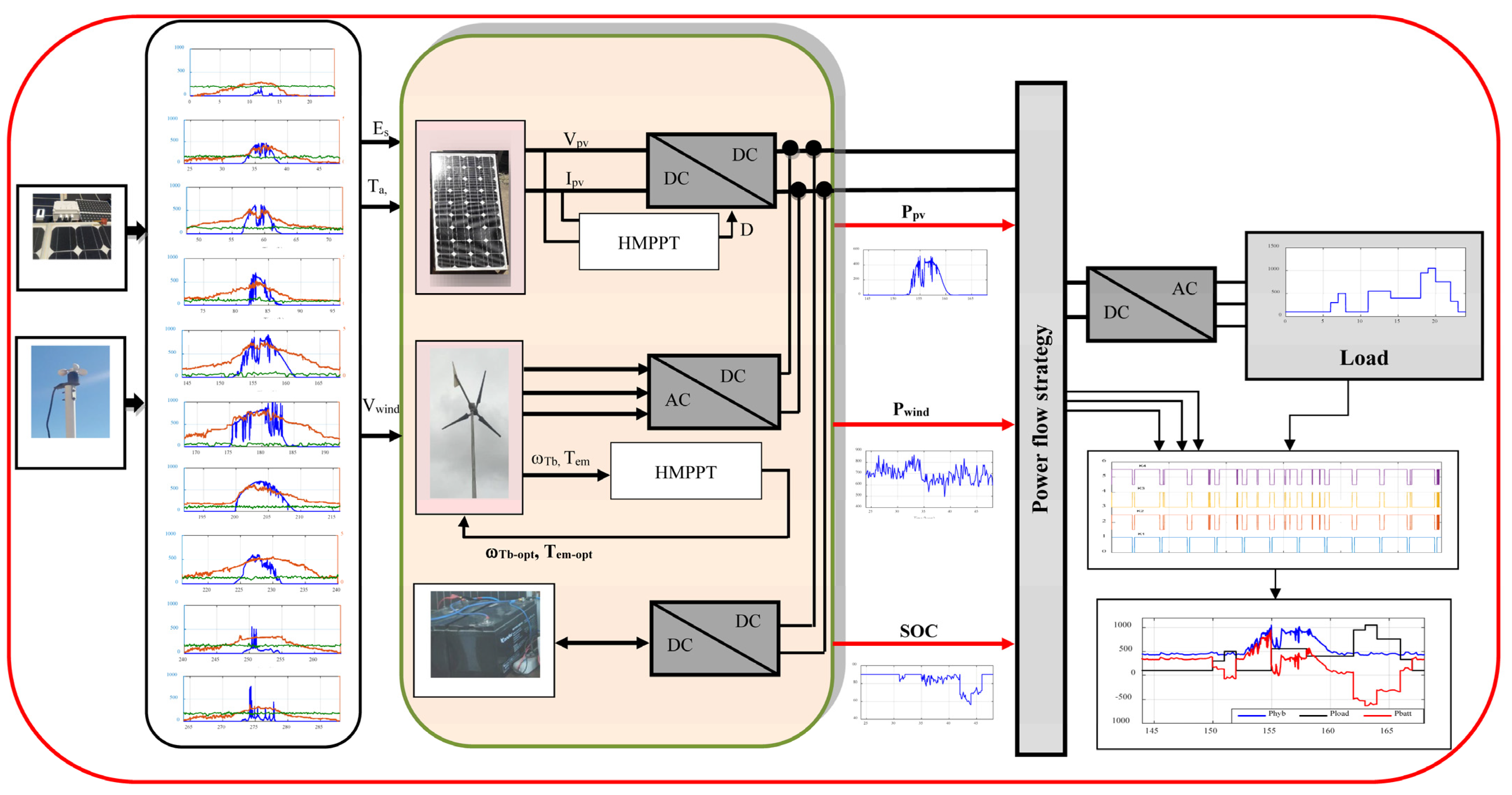
Figure 1. System description.
Energies 16 02286 g001
Figure 2. P&O algorithm principle. (a) Photovoltaic. (b) Wind turbine. Where: Ppv and Ipv are photovoltaic power and current, respectively, and PTb and ω Tb are power and mechanical wind turbine power, respectively.
Energies 16 02286 g002
Figure 3. AFLC structure.
Energies 16 02286 g003
Figure 4. Optimized PV and wind turbine powers.
Energies 16 02286 g004
Figure 5. Calculations of optimized powers in PV/wind turbine system.
Energies 16 02286 g005
Figure 6. Measurement acquisition device at the laboratory. Where: 1: wind speed sensor, 2: wind turbine, 3: data acquisition system, 4: solar irradiance and ambient temperature sensor, and 5: PV panel.
Energies 16 02286 g006
Figure 7. Profile of a typical day corresponding to each month in 2022 year. (a) January, (b) February, (c) March, (d) April, (e) May, (f) June, (g) July, (h) August, (i) September, (j) October, (k) November and (l) December.
Energies 16 02286 g007
Figure 8. Chosen power load profile.
Energies 16 02286 g008
Figure 9. Photovoltaic power.
Energies 16 02286 g009
Figure 10. Wind turbine power.
Energies 16 02286 g010
Figure 11. Hybrid power.
Energies 16 02286 g011
Figure 12. Battery power.
Energies 16 02286 g012
Figure 13. Control of battery.
Energies 16 02286 g013
Figure 14. Battery state of charge.
Energies 16 02286 g014
Figure 15. Battery voltage.
Energies 16 02286 g015
Figure 16. Proposed overall structure of the system under study.
Energies 16 02286 g016
Figure 17. Proposed power flow method.
Energies 16 02286 g017
Figure 18. Obtained logical switches.
Energies 16 02286 g018
Figure 19. Different obtained powers.
Energies 16 02286 g019
Table 1. PV and wind system configurations.
MonthsEir
(kWh/m2)
Ta
(°C)
Tj
(°C)
ηpvVwind (m/s)Epv
(kWh/m2)
Ewind
(kWh/m2)
ELoad
(kWh)
January180.1416.0021.630.11306.5015.90191.47664.82
February190.1114.0019.940.11386.0016.89136.03477.15
March200.4518.0024.260.11185.0017.5187.15311.52
April292.3219.0028.140.11014.7025.1470.05260.00
May200.0325.0031.250.10874.1016.9948.05178.13
June260.4128.0036.140.10654.2021.6749.99188.78
July290.7031.0040.080.10483.5023.7929.89122.29
August290.8036.0045.090.10253.7023.2935.32140.30
September185.5630.0035.800.10673.9015.4640.02149.51
October190.1022.0027.940.11025.5016.36116.00408.60
November190.1018.0023.940.11206.6016.63193.98673.97
December160.2614.0019.010.11426.8014.29219.23757.78
Epv,ave =
18.66
Ewind,ave =
101.43
ELoad,ave =
361.07
Table 2. The number of panels and wind turbines calculated.
k perc Spv (m2)Swind (m2)NpvNwindSpvfinal (m2)Swind,final (m2)ELmean (kWh)
0.000.003.560.002.000.006.90699.87
0.101.933.203.001.002.603.45398.52
0.203.872.855.001.004.343.45430.92
0.305.802.497.001.006.083.45463.31
0.407.742.149.001.007.813.45495.71
0.509.671.7812.001.0010.423.45544.30
0.6011.611.4214.001.0012.153.45576.69
0.6011.611.4214.001.0012.153.45576.69
0.7013.541.0716.001.0013.893.45609.08
0.8015.480.7118.001.0015.623.45641.48
0.9017.410.3621.001.0018.233.45690.07
1.0019.350.0023.000.0019.960.00372.53
Table 3. Component numbers.
PV PanelsWind TurbineBatteries
030102
Table 4. AFLC rules.
Error (e)Variation of Error (Ce)
NBNMNSZEPSPMPM
NBNBNBNMZEZEZEZE
NMNBNMNMZENMPSPS
NSNBNBNBNBPMPSPM
ZENBNBNSZEPSPMPB
PSNMNSZEPSPMPBPB
PMNSPBPBPBPBPBPB
PBZEPBPBPBPBPBPB
Where: NB, NS, NM, ZE, PM, and PB refer to linguistic terms used to describe the degree of membership. NB: “Negative Big” represents a high degree of negative membership, NS: “Negative Small” represents a moderate degree of negative membership, NM: “Negative Medium” represents a moderate degree of negative membership, ZE: “Zero”represents a neutral degree of membership, PM: “Positive Medium” represents a moderate degree of positive membership, PS: “Positive Small” represents a moderate degree of positive membership and PB: “Positive Big”—represents a high degree of positive membership.
Table 5. Literature review of some systems under study with their components with EMC.
YearSystem under StudyComponentsReferences
PVWTbBatteriesDiesel GeneratorFuel CellsHydropowerSC
2009Autonomous systemXXXXXX [40]
2010Autonomous systemX X X[41]
2012Micro-gridsXXX [42]
2013Domestic micro-grids X X [43]
2013Micro-gridsXX [44]
2014Traction motor X X X[45]
2014Autonomous network X X X [46]
2014Electric vehicleX X X [47]
2014Autonomous systemX X [48]
2015Electric carX X X [49]
2016Water pumping systemXXX [50]
2017Autonomous systemXXXX [51]
2017Electric vehicle X X[52]
2018Autonomous systemX X [53]
2018Hybrid vehicle X X [54]
2018Water pumping systemXXXX [55]
2019Autonomous systemXXXX [56]
2020Micro-gridsXXX [57]
2020Standalone systemX X X [58]
2020Grid-PV system X X X [59]
2021Micro-grid systemsXXXXXXX[60]
2021Isolated renewable energy system X X[61]
2021Isolated hybrid micro-gridsX XX [62]
2021Micro-grid systemsXX [63]
2021Micro-gridsXXXXXXX[64]
2021DC micro-gridsX X [65]
2022Micro-gridsXXX [66]
2022Micro-gridsXXXXX [67]
2022Stand-alone system XX [68]
2022Stand-alone systemXXX [69]
2022Electric vehicle X X X[70,71]
Table 6. Different states of the switches.
Switch StatesPowersSOC
K1 = 1K2 = 0K3 = 0K4 = 0Phyb = PLoadSOC
K1 = 1K2 = 0K3 = 0K4 = 1Phyb > PLoadSOC > SOCmax
K1 = 1K2 = 1K3 = 0K4 = 0Phyb > PLoad,SOC < SOCmax
K1 = 1K2 = 0K3 = 1K4 = 0Phyb < PLoad,SOC > SOCmin
K1 = 0K2 = 1K3 = 0K4 = 0Phyb < PLoadSOC < SOCmin
K1 = 0K2 = 0K3 = 0K4 = 1PLoad = 0, Phyb > 0SOC ≥ SOCmax
Disclaimer/Publisher’s Note: The statements, opinions and data contained in all publications are solely those of the individual author(s) and contributor(s) and not of MDPI and/or the editor(s). MDPI and/or the editor(s) disclaim responsibility for any injury to people or property resulting from any ideas, methods, instructions or products referred to in the content.