1. Introduction
In the first part of this two-paper work [
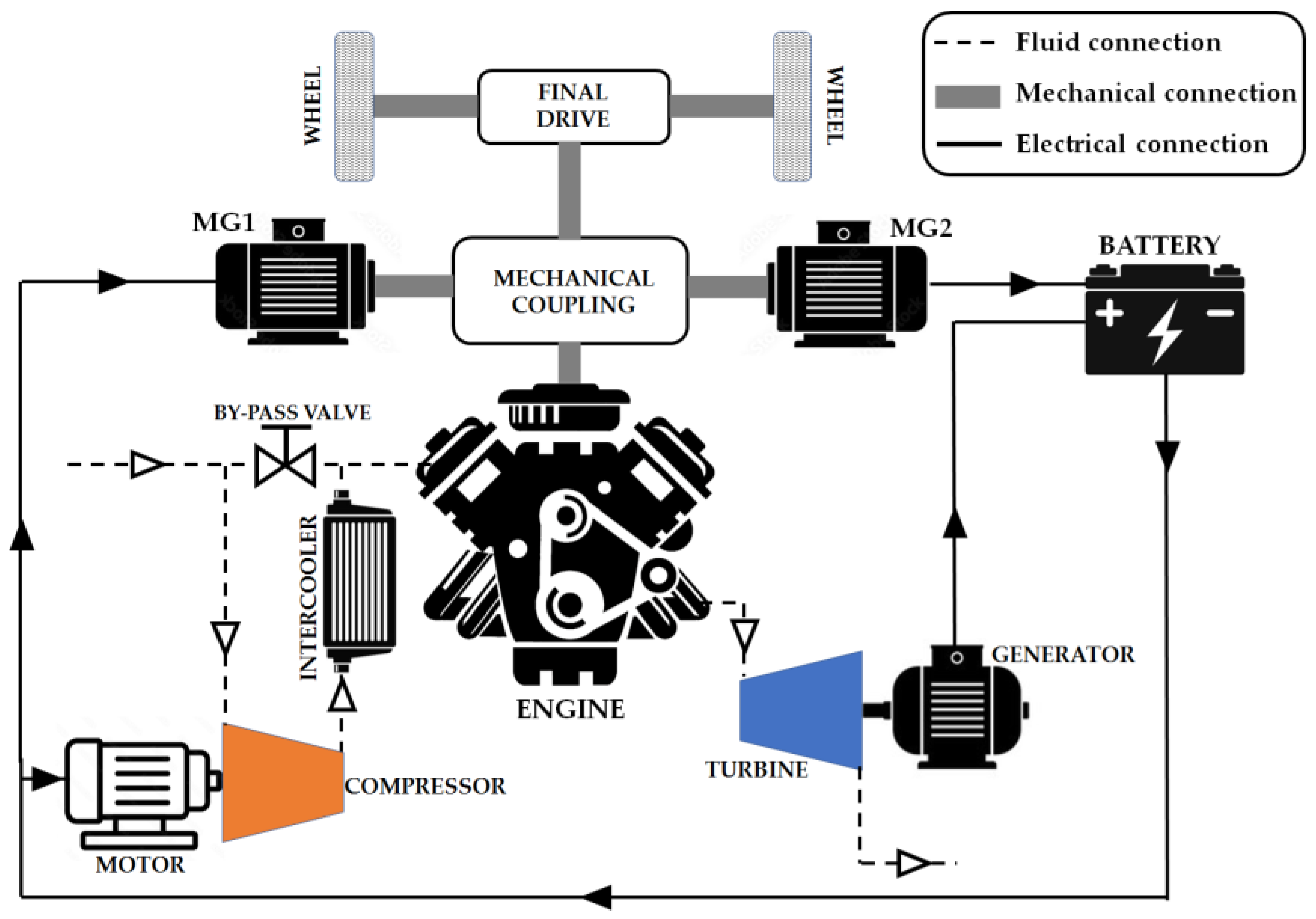
1], the authors introduced a new hybrid propulsion system (see
Figure 1) consisting of a supercharged spark ignition engine equipped with a specifically designed exhaust gas turbo-generator dedicated to completing exhaust gas expansion and converting the related amount of energy into electrical energy. As shown in
Figure 1, the electric energy produced by the turbo-generator is stored in the energy storage system of the hybrid vehicle and is available for vehicle traction; it must be noted that, in the system conceived, the compressor is connected to an independent electric motor and is powered only if supercharging is required (i.e., for the higher engine loads). The described architecture is called a separated electric compound engine, since the exhaust gas turbine and the compressor are mechanically decoupled, thus letting their operating conditions be independent of each other.
Some preliminary evaluations made by the same authors [
2,
3,
4] showed that the separated electric compound engine has good potential, since vehicle fuel economy increments up to 15% may be obtained in comparison to a reference hybrid propulsion system endowed with a traditional turbocharged engine with equal maximum output power (73.5 kW). It was also found that the turbo-generator could contribute to vehicle traction by about 34% of the overall power generated for the propulsion, with a maximum delivered power of about 20 kW. As pointed out in Part 1 [
1], the exhaust gas turbine here considered should be different from the turbines commonly employed for turbocharging purposes. First of all, it should be optimized for power production, rather than for compressor driving; moreover, considering that the thermal engine of a hybrid propulsion system is not involved in the strong and rapid load and speed variations of the engine in a traditional vehicle, the exhaust gas turbine should be designed for quasi-steady operation. As also clarified in Part 1, the authors focused on radial turbines rather than on multi-stage axial turbines, intending to obtain a good compromise between machine size and efficiency [
5,
6,
7]. It was also established that, for the application considered, the most suitable kind of radial turbine is represented by a variable nozzle turbine, whose nozzle angle variations allow adapting to any engine exhaust mass flow for any required pressure ratio [
8].
Considering the mentioned power rating of about 20 kW (for an overall output power of 73.5 kW), it was found that such a turbo-generator is not available on the market, nor have its characteristics been studied or developed in the scientific literature. Due to this lack of information, preliminary evaluations [
2,
3,
4] were performed considering a constant turbine efficiency, i.e., independent from the speed of rotation or the pressure ratio; in their previous studies, the authors considered two different levels for the thermomechanical efficiency (i.e., the product of the mechanical efficiency
ηT,m and the total-to-static isentropic efficiency
ηT,ts), namely, 0.70 and 0.75. These values are higher than the efficiency of turbines commonly used for turbocharging, on account of the more favorable working condition already mentioned, which allows a design strategy for the best efficiency under steady operation, and also permits the electric generator to control the turbine speed of rotation, maximizing its efficiency, apart from the power produced.
Preliminary evaluation of the energetic advantages of the separated electric compound engine was hence carried out under the hypothesis of a constant-efficiency turbine. Aiming then to assess the realistic performance and advantages attainable by the compound engine, the authors decided to implement in their calculation a proper turbine model for a reliable evaluation of the turbine efficiency. On account of this, in Part 1 the authors described a design algorithm that can be employed for the definition of the geometry of a radial inflow turbine, together with a complete model for the evaluation and verification of its performances. In this paper, Part 2, the authors, first of all, determined the turbine dimensions and properties based on the mass flow requirements and pressure ratios calculated in their previous studies. Once the main characteristics of the turbine were established, the realistic performances of the separated electric compound engine were evaluated, taking into account the real turbine efficiency obtained, for each mass flow and pressure ratio involved, through the 1-D turbine performance prediction model.
2. Definition of the Turbine Design Condition
The design algorithm explained in Part 1 requires, as the first input, the nominal operating condition of the exhaust gas turbine. For this purpose, in this paper, Part 2, the authors decided to base the design of the exhaust gas turbine starting from the operating conditions determined for the turbine of the Compressed Natural Gas (CNG)-fueled separated electric compound engine evaluated in [
2].
The operating conditions of the previously studied compound engine, reported in
Figure 2, were identified through an optimization calculation procedure based on the use of a genetic algorithm, determining, for each load and speed of the engine, the best exhaust back pressure
PEX which maximized the overall brake thermal efficiency
ηCOMP of the compound system:
where
GF is the fuel mass flow rate and
LHV is the fuel lower heating value.
POWCOMP represents the overall output power of the compound system, composed of the engine output power
POWENG, with the addition of the power produced by the exhaust gas turbine (here called recovery power
POWREC), and reduction due to the power required for supercharging
POWSC:
It is worth pointing out that, as also clarified in the previous works [
2,
3], the efficiency of the electric motor (0.90) connected to the supercharger was considered when computing the power required for air pressure boosting. As regards the turbine, instead, the efficiencies of both the electric generator and the battery charging were not taken into consideration, coherent with the approach adopted for the spark ignition engine, whose power division between motor-generator MG1 and wheels (as shown in
Figure 1) should depend on the particular mechanical coupling, which is not defined in the calculations performed in this paper. Both the battery charging and the generator efficiency can be considered to assume the same values also for the comparative hybrid propulsion system equipped with the traditional turbocharged engine. Such considerations induced the authors to fairly base the comparison on the mechanical output power produced.
The modeling approach adopted by the authors in the previous work, as well as the calculation procedure followed to optimize the overall brake thermal efficiency of the compound engine, are described in detail in [
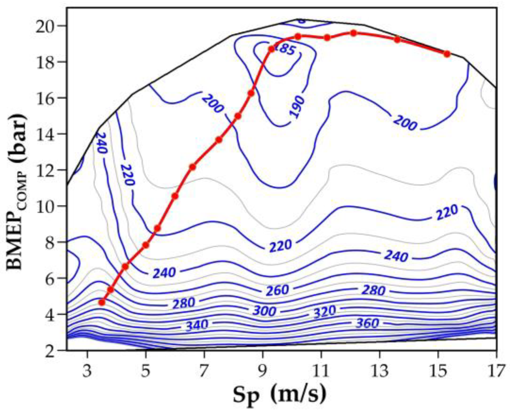
2]; it is worth remembering that, in their previous works, the turbine was assumed to have a constant thermomechanical efficiency, regardless of the particular operating condition; the final result is shown in
Figure 3, where the specific fuel consumption map of the CNG-fueled compound engine is reported as a function of the mean piston speed
Sp and overall brake mean effective pressure
BMEPCOMP:
where
VCOMP and
nCOMP denote the displacement and the speed of rotation of the thermal engine of the compound system, while
εENG is the number of engine rotations per cycle (two in a four-stroke engine).
It is worth noting, however, that the thermal engine of a hybrid propulsion system should work close to its best efficiency condition, to maximize the fuel economy of the vehicle; on account of this, the authors also calculated the best fuel economy curve of the compound system (shown in
Figure 3), i.e., the curve connecting the operating conditions (
BMEPCOMP and
Sp) which ensure, for each overall power request, the maximum overall efficiency. Obviously, to each point of the best fuel economy curve of the compound engine corresponds a particular operating condition of the turbine, in terms of exhaust mass flow rate
G and turbine pressure ratio
βT;
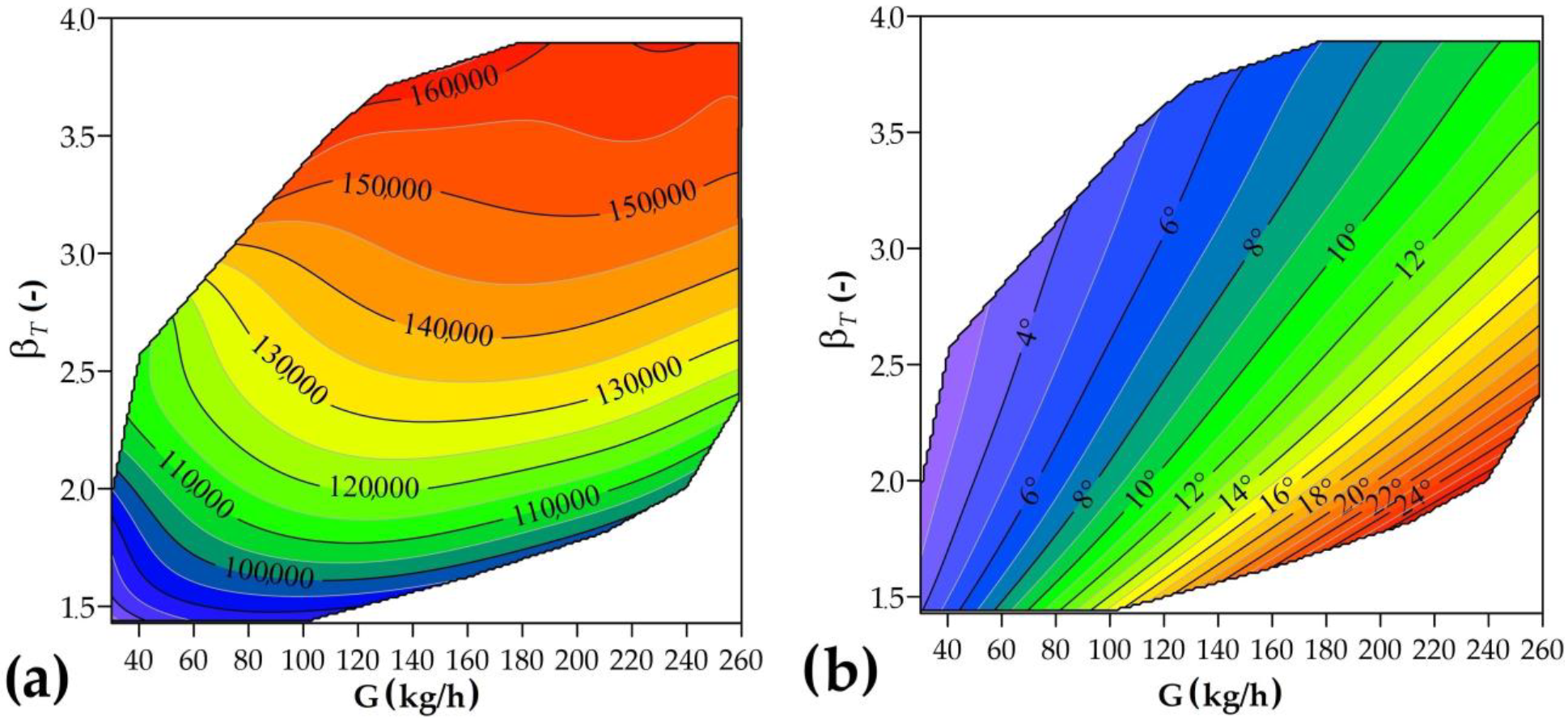
Figure 4 shows the turbine mass flow rate and pressure ratio related to the best fuel economy curve of the preliminary compound engine [
3], as a function of the overall output power.
3. Turbine Geometry and Performance
The present work aims to provide a more precise and reliable estimation of the performances of the separated electric compound system by adequately evaluating the turbine efficiency corresponding to each operating condition and thus avoiding the simplifying assumption adopted in the preliminary studies, in which the turbine efficiency was assumed to be constant. After selecting the reference operating conditions of the turbine, the authors proceeded with its design. To obtain the best performance for each operating point of the propulsion system, the geometry of the turbine was determined by employing an optimized design procedure; this procedure consisted of the application of the design algorithm (described in Part 1 of this work) considering a particular set of design variables (i.e., the mass flow rate
G, the pressure ratio
βT, and the rotational speed of turbine rotor
n), followed by the evaluation of the turbine efficiency over the entire range of operating conditions reported in
Figure 4; the turbine efficiency was evaluated employing the performance prediction model presented together with the design algorithm in Part 1.
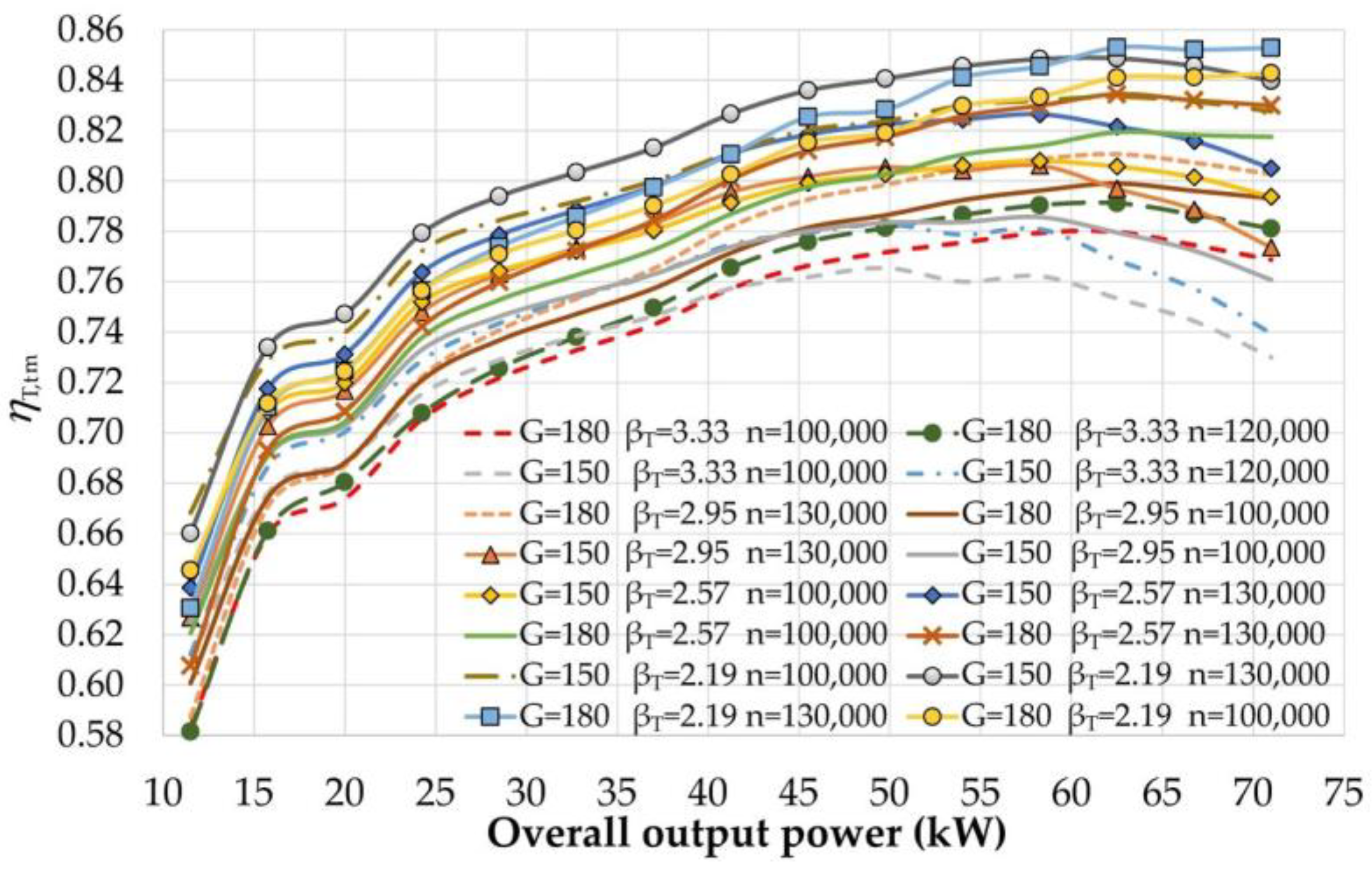
Figure 5 shows some of the results obtained by implementation of the optimized design procedure, which was repeated for many different sets of the three design variables; as shown in
Figure 5, the best solution was obtained by adopting the design values
βT = 2.19,
n = 130,000 rpm, and
G = 150 kg/h: the resulting curve of the thermomechanical efficiency
ηT,tm revealed the best over most of the operating range, with an average value of
0.804.
Table 1 resumes the parameters and conditions assumed for the design of the radial turbine of this work, while
Table 2 reports the details of the geometry resulting from the use of the design algorithm;
Figure 6 offers a schematic representation of the radial turbine, with the details of the principal sections considered in the mean-line model. The several drawings included in [
1] are, however, recommended for a complete interpretation of the geometric parameters reported in
Table 2.
The turbine performance prediction model, employed on the final geometry of the turbine (resumed in
Table 2), allowed tracing of the typical mass flow parameter (MFP) curves, reported in
Figure 7, as a function of the turbine pressure ratio (
βT) and for different values of the nozzle blade angle (
α3,g). It is clearly shown that, as desired, the variable nozzle turbine designed for the present work is fully able to swallow a wide range of mass flow rates through the variation of the nozzle blade angle. At this point, it is necessary to highlight a fundamental difference between the separated electric compound system and a traditional turbocharged engine. In the common turbocharging application, the turbine is mechanically linked to the compressor and its speed of rotation is governed by the fluid dynamics of the complex system constituted by the compressor, the engine, and the turbine; in the compound system here considered, instead, the turbine is not connected to the compressor, and hence its speed of rotation is not constrained. This gives the compound system an additional degree of freedom; in effect, the variable nozzle turbine may adapt to each engine exhaust mass flow and pressure ratio with infinite values of the rotor speed, each one corresponding to a single nozzle blade position. This implies that, in the separated electric compound engine, a double control action must be performed on the turbine, properly setting both the rotor speed (controlled by means of the electric generator) and the nozzle blade angle.
According to these considerations, the authors evaluated, for each exhaust mass flow and pressure ratio, the turbine thermomechanical efficiency with varying rotor speed, evaluating for every single case the nozzle blade angle required to comply with the mass flow.
Figure 8 reports some of the results obtained and clearly shows that, for each engine exhaust mass flow and pressure ratio, a single value of the rotor speed of rotation (to which corresponds a proper nozzle blade angle) allows maximization of the turbine efficiency. On account of this, and to let the turbine operate always at its best efficiency, the authors evaluated, for each exhaust mass flow and pressure ratio, the rotor speed of rotation which maximizes the turbine efficiency, together with the related nozzle blade angle; the resulting optimal values of both rotor speed and nozzle blade angle are shown in the graphs.
In
Figure 9, it is hence assumed that, whichever is the operating condition of the exhaust gas turbine, the rotor speed of rotation and the nozzle blade will be set to their best efficiency values. It can be clarified now that the turbine efficiency optimization calculation was also followed for each of the several turbine geometries evaluated during the design and validation procedure: this means that every value reported in
Figure 5 represents the best efficiency of the turbine for one of the operating condition reported in
Figure 4.
As could be expected, the implementation of the mean-line prediction model allowed obtaining of realistic turbine efficiency values different from the constant values assumed in previous works [
2,
3] (i.e., 0.70 and 0.75).
Figure 10 reports the turbine thermomechanical efficiency predicted by the model, as a function of the exhaust mass flow
G and pressure ratio
βT. As shown, the thermomechanical efficiency of the designed turbine ranges between the minimum value of 65% and the maximum value of 84%, with the best efficiencies located in the high-pressure/-mass-flow-rate region.
4. Realistic Turbo-Compound Engine Performances
As mentioned, the task of this two-paper work is to evaluate the realistic advantages attainable by the implementation of the separated electric compound engine in a hybrid propulsion system. For this purpose, a CNG-fueled SI compound engine was calculated following the modeling approach already illustrated in [
2] and adopting the newly designed turbine geometry, whose thermomechanical efficiencies were evaluated, for each operating condition, through the mean-line model presented in Part 1. As already established in previous papers [
2], to perform a comparison with a traditional turbocharged engine based on an equal power basis, the compound engine was designed to deliver an overall output power of 73.5 kW: this means that, as fully described in [
2], having evaluated the specific performances in terms of brake mean effective pressure, the displacement of each engine was sized to ensure the same output power of 73.5 kW (which corresponds to 100 HP). The realistic efficiency of the compound engine will then be compared to the efficiency of a reference turbocharged engine of the same nominal output power, whose specification and performance data are already given in the reference paper [
2]. It is worth mentioning that both the compound engine and the reference turbocharged engine have been supposed to be developed starting from the same baseline naturally aspirated engine. Moreover, the reference thermal unit was supposed to be equipped with a turbocharger whose efficiency map perfectly complies with the engine: in other words, the turbocharger was supposed to perfectly fit the reference engine. The only peculiarity of the calculations performed in the present paper regards the evaluation of the exhaust gas temperature
TEX at the turbine inlet, which (as adequately described in the reference paper) was evaluated based on the ratio between the in-cylinder gas temperature
TEVO at the exhaust valve opening (EVO) and the inlet gas temperature
TIVC at intake valve closure (IVC). In modern spark ignition engines, the ratio
TEVO/TIVC usually ranges between
3.5 and
4.5, depending on the particular engine and its operating condition; in the present paper, the ratio
TEVO/TIVC was assumed to remain constant and equal to 4 for both the compound engine and the reference turbocharged engine.
As could be easily imagined, the realistic behavior of the turbine influenced substantially the performance of the compound engine, increasing the energy recovery at the higher power levels, where the realistic turbine revealed a better efficiency. The implementation of the realistic turbine efficiency map required hence a new optimization of the whole compound engine whose purpose is to maximize the overall brake thermal efficiency
ηCOMP of the compound system for each operating condition. More specifically, the optimization process mainly regards the engine exhaust pressure level to be adopted for each operating condition of the compound engine; as is obvious, increasing the engine exhaust pressure produces an increment in the energy transformed by the turbine, but, at the same time, worsens the indicated efficiency of the engine, due to the increased residual gas fraction. As mentioned, a genetic algorithm was employed for the system efficiency optimization, since the latter is not a linear or polynomial function of the engine exhaust pressure.
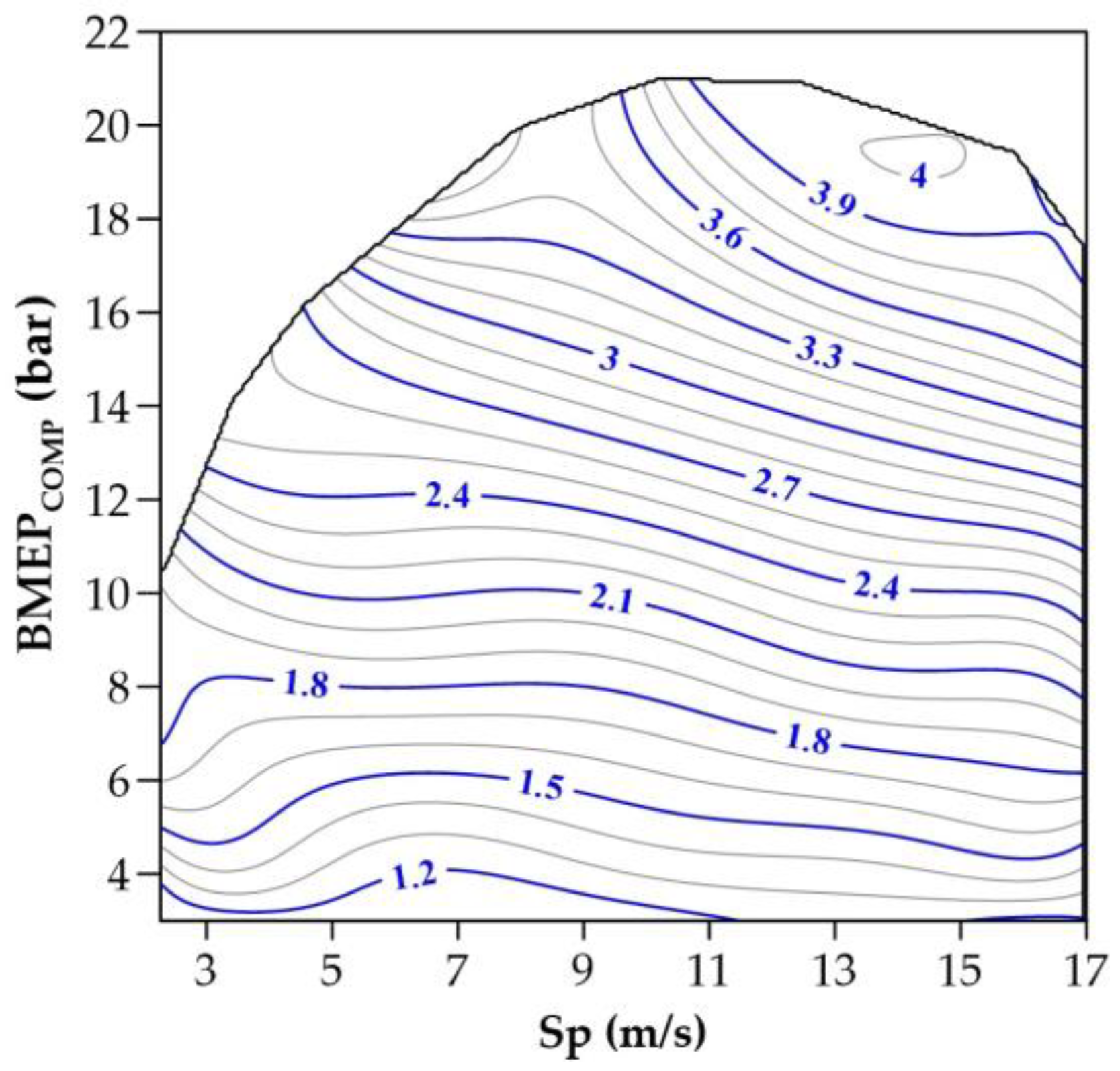
Figure 11 reports the contour map of the new optimal exhaust pressure levels obtained for each overall brake mean effective pressure of the compound engine
BMEPCOMP and mean piston speed
Sp, thanks to the implementation of the realistic turbine efficiency characteristic.
As can be observed in
Figure 11, exhaust pressures up to 4.0 bar were determined in the high-load/-speed region, which can be easily explained considering that higher engine power implies higher in-cylinder pressures and exhaust mass flows. In these conditions, the turbine can provide a greater contribution to the overall output power of the system without compromising the engine indicated efficiency, leading to greater exhaust gas energy recovery.
The same
Figure 11 also shows that the optimal exhaust pressure levels are significantly higher than in a traditional turbocharged engine; additionally considering the related exhaust gas temperature (between 980 and 1120 K, as reported in
Figure 12), this further confirms the appropriateness of the gas turbine for the energy recovery, since its state of the art already complies with the boundary conditions imposed by the particular task. The high optimal exhaust pressure levels also point out the necessity of a proper turbine design algorithm, as well as of a reliable model for the turbine efficiency prediction, which certainly allows obtaining of more realistic evaluations of the separated electric compound engine efficiency.
The new optimization process led to an update of the maximum
BMEPCOMP levels for each mean piston speed of the compound engine, and, as a consequence, also the new compound engine displacement
VCOMP necessary to develop the maximum target power of 73.5 kW. The resulting specifications of the updated compound engine are summarized in
Table 3. As shown, compared to the reference turbocharged engine, a reduction in the minimum brake-specific fuel consumption of −11.50% was obtained by the new optimized compound engine.
Table 3 also shows that the maximum percentage contribution of the exhaust gas turbine to the overall output power increased up to 38.7%, which denotes a remarkable increment compared to the values previously obtained assuming a constant efficiency turbine (29.7% and 33.9% with the constant turbine efficiency of 0.70 and 0.75, respectively): this is a further confirmation of how the appropriate evaluation of the real turbine capability may be fundamental for a reliable performance evaluation of the whole compound system. A higher efficiency turbine allows better exploitation of the exhaust gas expansion, altering the proportion between the power delivered by the turbo-generator and by the engine: this is also confirmed by the new maximum power delivered by the exhaust gas turbine, which reached 21.97 kW and revealed values higher than the values determined in the preliminary study (17.82 kW and 19.64 kW with the constant turbine efficiency of 0.70 and 0.75, respectively).
Figure 13 shows the contour maps of the overall specific fuel consumption
BSFCCOMP obtained for the realistic compound engine, while the map shown in
Figure 14 refers to the reference turbocharged engine; it can be noted that, compared to the reference traditional turbocharged engine, the compound engine exhibits a lower fuel consumption for every engine speed and load. A clearer evaluation of the advantages related to the implementation of the compound system is given in
Figure 15, which reports the efficiency improvement of the realistic compound engine compared to the reference turbocharged engine, as a function of mean piston speed and overall output power. As can be observed, the efficiency improvements are limited (+4%) at the minimum power levels and increase with the power output, reaching a maximum value of 19%; this trend can be easily explained, since higher engine power imply higher in-cylinder pressures and exhaust mass flow rates, which, as shown in
Figure 10, represent the conditions for which the turbine reveals its best efficiencies, and hence the conditions in which the turbine can provide a greater contribution to the overall output power of the system without compromising the engine indicated efficiency.
The efficiency comparison carried out in
Figure 15 may, however, be incomplete when considering two propulsion units for a hybrid vehicle. In a hybrid propulsion system, in effect, the operating point of the thermal unit should remain close to the best efficiency curve, i.e., the curve connecting the operating conditions (i.e., engine load and speed), which ensures the best efficiency for a given power output level. For this reason, a comparison performed taking into consideration only the best performance of each propulsion system for every power level could have greater significance. On account of this consideration, the authors carried out a further comparison, focusing on the best efficiency curves of both the realistic compound engine and the reference turbocharged engine. The result of this further comparison is shown in
Figure 16, where, for each power level, the best efficiencies of both propulsive solutions are compared. As can be noted, a maximum 17.9% efficiency improvement is obtained by the compound engine for the overall output power of 64 kW; a minimum 3% efficiency increment is instead obtained for the overall output power of 8 kW, while the average efficiency increment on the whole output power range is 10.9%.
For purposes of comparison, it is worth mentioning that, in their previous analysis, when the turbine efficiency was considered constant and equal to 0.75, the authors estimated a maximum overall efficiency improvement of 15.6% compared to the same reference turbocharged engine, with an average increment of 10.2% on the whole power range.
5. Conclusions
In this two-paper work, the authors carried out a realistic evaluation of the efficiency improvement attainable by the implementation of a new propulsion system for hybrid vehicles. The new system comprises a supercharged spark ignition engine endowed with a properly designed exhaust gas turbo-generator dedicated to completing the expansion of the exhaust gas and recovering the related energy. The supercharger is driven by an independent electric motor, and for this reason, the system is referred to as a separated electric compound engine. This system was previously studied by the same authors both in the gasoline and in the natural gas fueling version, with very encouraging results. Some simplifying assumptions, mainly related to the turbine efficiency, which was supposed to be constant, however, detracted from the reliability of the results obtained. In the present two-paper work, the authors aim to obtain a more realistic evaluation of the performance attainable by the separated electric compound engine taking into account the plausible thermomechanical efficiency of the turbine, which should depend on the operating condition.
In Part 1, the authors first focused on the selection of the proper kind of machine; some thermodynamic and fluid dynamic evaluations based on previously obtained results allowed selection of the radial variable nozzle turbines as the best compromise between compactness and performance. Successively, a simple but reliable model based on a mean-line approach was developed for the estimation of the turbine’s realistic efficiency in all the operating conditions. An effective but simple design algorithm was also presented, which, through some simplifying assumptions, allows fast determination of the main geometric dimension of the turbine.
In this paper, Part 2, the authors first dedicated to the definition of the best turbine design. The design algorithm presented in Part 1 was employed, also implementing an optimization process that allowed maximization of the efficiency of the turbine on the whole range of utilization of the compound engine. Having determined the best turbine geometry, its realistic performances were evaluated through the mean-line model presented in Part 1, also determining the characteristic map of the turbine. Considering the operating range connected to the best efficiency curve of the compound engine, the mean-line model evaluated an average thermomechanical turbine efficiency of 0.804. The performance prediction model also highlighted the strong connection between the turbine operating conditions and its thermomechanical efficiency, which was found to range between the minimum value of 0.65 obtained at the smallest pressure ratio and mass flow rates, and the maximum value of 0.84 resulting at the higher-pressure ratios and mass flow rates. Some relevant observations regarding the double control action which is required for the application to the compound engine are also given in Part 2.
The realistic turbine efficiency evaluations carried out through the turbine mean-line model allowed determination of the plausible energetic advantages of the separated electric compound engine in comparison with a reference turbocharged engine (both characterized by the same nominal output power). As expected, the variation of the realistic turbine efficiency on its operating map substantially modified the performance obtainable by the compound engine, resulting in a better exhaust gas energy recovery in the high-output power region.
Resuming the result obtained, the comparison with the traditional turbocharged engine revealed efficiency improvements of the new separated electric turbo-compound engine between 3.1% and 17.9%, depending on overall power delivered. The average efficiency increment, evaluated on the whole best-efficiency curve, was revealed to be 10.9%.
Considering that vehicle electrification is currently one of the key technologies for achieving significant CO2 emission reduction from the transport sector, the study carried out could provide innovative contributions to the current state-of-the-art of hybrid electric vehicles, given the lack in the current scientific literature of detailed studies related to the evaluation of the potential of separate electric turbo compound systems.


 ,
, 


