Article

Common-Mode Voltage-Reduction Method of 7-Phase BLDC Motor Control System †

1
Department of Mechanical Facility Control Engineering, Korea University of Technology and Education, Cheonan 31253, Republic of Korea
2
Department of Research and Development, Hyowon Powertech Company, Busan 46241, Republic of Korea
3
Air Mobility Electric-Motor & Drive Research Team, Korea Electrotechnology Research Institute (KERI), Changwon 51543, Republic of Korea
4
Department of Electrical and Electronics Engineering, Pusan National University, Busan 46241, Republic of Korea
*
Author to whom correspondence should be addressed.
This paper is an extended version of our paper published in 2019 10th International Conference on Power Electronics and ECCE Asia (ICPE 2019—ECCE Asia).
Energies 2023, 16(5), 2097; https://doi.org/10.3390/en16052097
Submission received: 17 January 2023 / Revised: 6 February 2023 / Accepted: 18 February 2023 / Published: 21 February 2023
(This article belongs to the Topic Advanced Electrical Machines and Drives Technologies)

Abstract

:
This paper describes a method for reducing the common-mode voltage in a seven-phase brushless DC motor (BLDC) drive. The conventional interleaved method used in the three-phase inverter system is extended and applied. The proposed phase-phase interleaved method is studied to apply the six-phase excitation method for controlling the seven-phase BLDC. The six-phase switching functions related with modulation index (MI) and interleaved angle are obtained, and the average of the common-mode voltage is derived mathematically. The proposed control method reduces the common-mode voltage generation by applying the optimal interleaved angle according to MI. The proposed method is verified by experimental results.

1. Introduction

Recently, multi-phase motors have been widely used in electric propulsion, ships, and traction. The use of a multi-phase motor can reduce the torque ripple and increases the output power density compared to three-phase motors [1,2,3]. The use of a multi-phase motor is essential, especially in a system requiring high power with limited space, such as underwater propulsion. In addition, the multi-phase motor has the advantage of fault-tolerant control [4,5,6,7,8,9]. When one or more phases suffer a fault, the multi-phase motor can be still operated at a lower output power. For the control methods of a multi-phase motor, there are generally the hysteresis control method [7] and the vector control method [8]. The hysteresis control method is easy to implement, but it is difficult to predict the heat generated in the system because the switching frequency is variable. The vector control method has the feature of low torque ripple, but it requires complex coordinate transformation including low-order harmonics. In this paper, the current control method, namely the control principle of a three-phase BLDCM, is used. In this case, the back-electro-motive force (EMF) voltage is a square wave, and the six-phase current is controlled in the square wave [9,10]. There is a hybrid-phase excitation method varying the number of excitation phases according to the operation speed and efficiency. The advantage of the BLDCM control method is that it is easy to implement. In addition, since each phase current is controlled independently, it is effective in reducing the torque ripple in the commutation period.
Generally, a motor used in underwater vehicles is operated in the high-speed region. Operation in a high-speed region causes current delay due to the increased reactance of the stator winding and increased back-EMF voltage [11]. In addition, the insufficient number of current samplings causes some errors of the control and torque pulsation. Thus, one method to solve torque pulsation is to increase the current control frequency and the switching frequency [12]. Therefore, a superior power device, namely silicon carbide (SiC) MOSFET, is needed to achieve high-frequency switching control [13,14,15]. However, the use of SiC-MOSFET causes an increase in common-mode noise due to the ringing of the output voltage and rapid variation of dv/dt. Thus, this paper presents the control performance according to the switching frequency of a SiC-MOSFET inverter, and the common-mode voltage-reduction method is proposed to solve the EMI noise problem.
Figure 1 shows the loop of conduction noise. The common-mode voltage (Vcm) is the voltage generated by the switching operation measured between the DC neutral point and the neutral point of the motor. Normally, there are parasitic capacitor (Cs) components among the ground and case of inverter and case of motor. Thus, the current (ig) defined as leakage current is generated by voltage variation of Vcm, and this current flows through Cs. This current loop is defined as a common-mode loop, which causes bearing damage in the motor drive system. Thus, the reduction of common-mode voltage is the main issue to solve in EMI problems.
Various methods have been studied to reduce the common-mode voltage. The most effective method is to design a passive filter at the output of the inverter [16,17]. The common-mode choke is specialized in reducing the magnitude of the common-mode current [18], and applying the L-C filter between phases helps to reduce the differential mode noise [19]. Based on the passive filters, the active component is used to additionally remove the common-mode noise and reduce the filter size [20]. However, these common-mode noise reduction methods by using a passive filter are sensitive to system configuration. thus, it is difficult to apply in a system operating at various switching frequencies [21,22,23]. In addition, the use of passive filters significantly increases the system volume in the multi-phase motor drive system operated in limited space.
Another method to reduce the common-mode voltage is to combine the pulse width modulation (PWM). The conventional space vector pulse width modulation (SVPWM) and sinusoidal pulse width modulation (SPWM) generate the maximum magnitude of common-mode voltage at zero vector. Thus, the near-state PWM method [24] and active zero state PWM method [25] use additional vectors instead of zero vector in the 3-phase SVPWM. In multi-phase motor control, some studies have researched reducing the common-mode voltage based on the SVPWM [19,20,21,22,23,24,25,26,27,28,29,30,31,32]. These methods are suitable for vector control in synchronous coordinate frame but are not available for the hybrid-phase excitation method [9]. This represents a lack of research of the common-mode voltage reduction in multi-phase BLDC motor drive system. Therefore, in this paper, the carrier interleaving method in the three-phase inverter is extended to the six-phase hybrid excitation method [26]. In our previous work [27], the interleaving angle according to the modulation index (MI) was calculated to generate the minimum common-mode voltage. The proposed interleaved method was verified in MATLAB simulation. In this paper, the control performance of the high-speed multi-phase motor was improved by increasing switching frequency. The use of SiC-MOSFET was able to achieve the above results. In addition, the common-mode noise generation for high switching frequency was experimentally confirmed. At last, the noise reduction method proposed in [27] was experimentally demonstrated and analyzed.

2. Basic Control Method of the 7-Phase BLDC

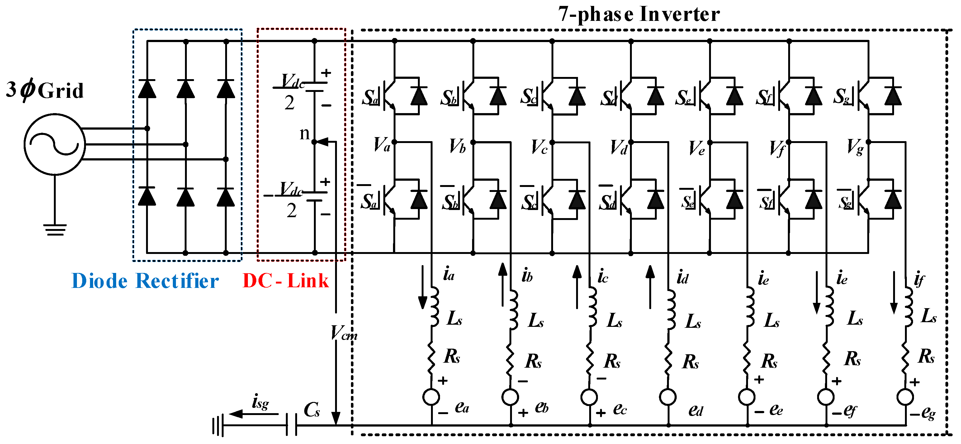
2.1. Mathematical Modeling

The 7-phase inverter system consists of a diode rectifier that converts AC power to DC, a DC-linked capacitor bank, a 7-phase inverter with 14 switches, and an electric motor as shown in Figure 2. A 7-phase BLDC motor is equalized with stator resistance (Rs), stator inductance (Ls), and back-EMF proportional to the motor rotational speed. The common-mode voltage (Vcm) represents the potential difference between the neutral point of the motor and the neutral point of the DC-linked capacitor bank, and Cs is the parasitic capacitor component that exists between the neutral point of the motor and the case of the motor. Assuming that the case of the motor is grounded, current flows through Cs when the common-mode voltage changes rapidly, which is called leakage current (isg) [17]. When the voltage is applied to the motor by the inverter operation, considering the mutual inductance component between the lines, the voltage equation can be expressed as Equation (1), where Vxn is the pole voltage of 7-phase inverter, ix is the phase current of each phase, Lij is the inductance of each phase, ex is the back-EMF of each phase, and Vsn is the neural voltage. Self-inductance and mutual inductance are defined as Equation (2).
V x n = R s i x + L i j d i x ( N ) d t + e x + V s n x = { a ,   b , c , d , e ,   f , g }     i ,   j = { a ,   b , c , d , e ,   f , g } ,   ( i j )
[ L i j ]   =   [ L s M a b M a c M a d M a e M a f M a g M b a L s M b c M b d M b e M b f M b g M c a M c b L s M c d M c e M c f M c g M d a M d b M d c L s M d e M d f M d g M e a M e b M e c M e d L s M e f M e g M f a M f b M f c M f d M f e L s M f g M g a M g b M g c M g d M g e M g f L s ]
Since a 7-phase BLDC is in a y-connection and balanced state, the sum of seven-phase currents becomes zero, as in Equation (3). Using the Equations (1)–(3), Vsn can be calculated as Equation (4).
i a + i b + i c + i d + i e + i f + i g = 0
V s n = 1 7 x = a g ( V x e x )
The normalized output power considering the excitation method is expressed as Equation (5), where N is the number of the excited phase, ES is the maximum value of back-EMF, and IS is the maximum value of phase current.
P e ( N ) = n = a g ( e n i n ) = N E s I s ( N )
In addition, electrical output torque can be expressed as Equation (6), where ω m is the mechanical angular speed, and k e is the back-EMF constant.
T e ( N ) = P e ( N ) ω m = N E s I s ( N ) ω m = N k e ω m I s ( N ) ω m = N k e I s ( N )

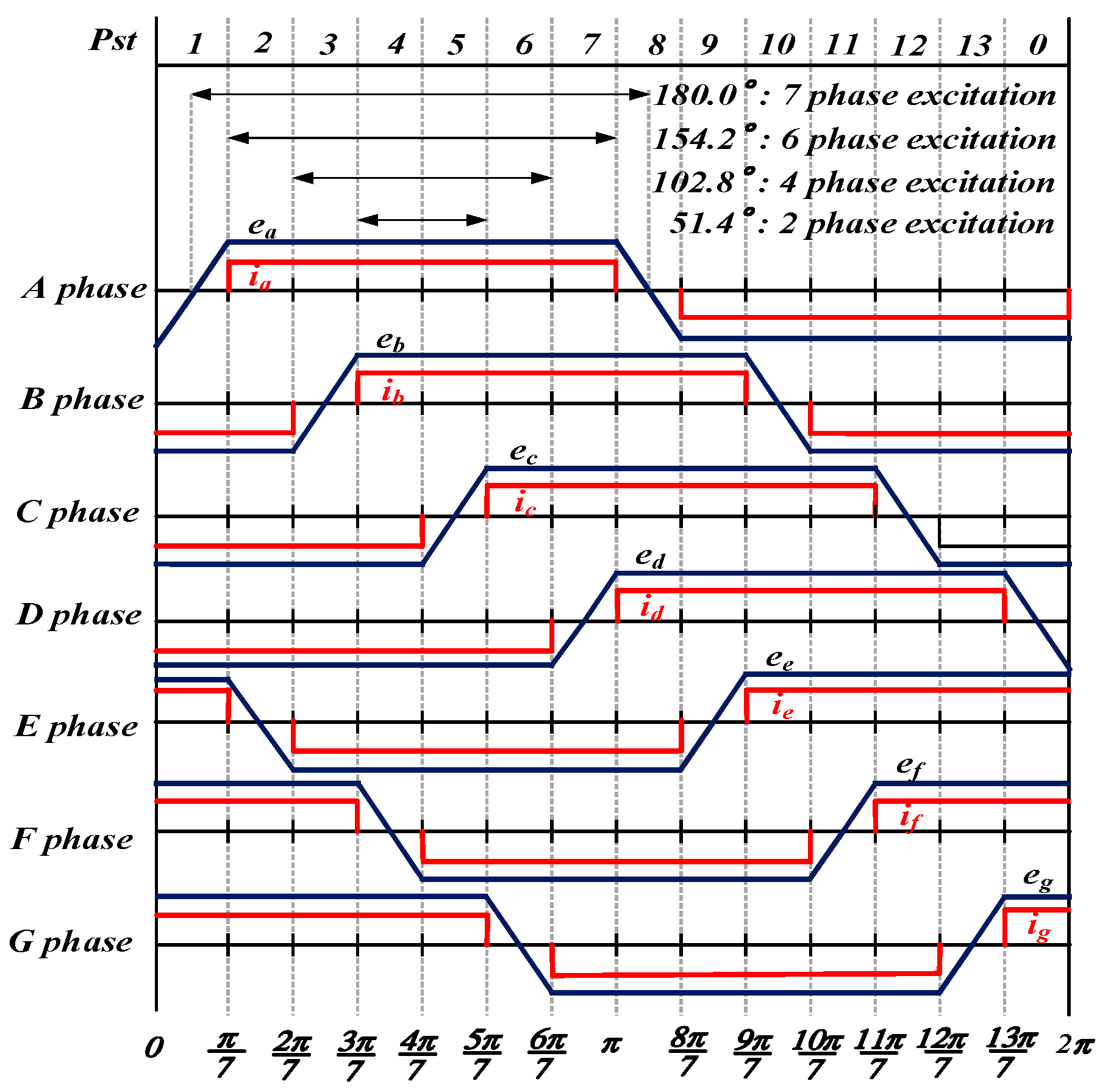
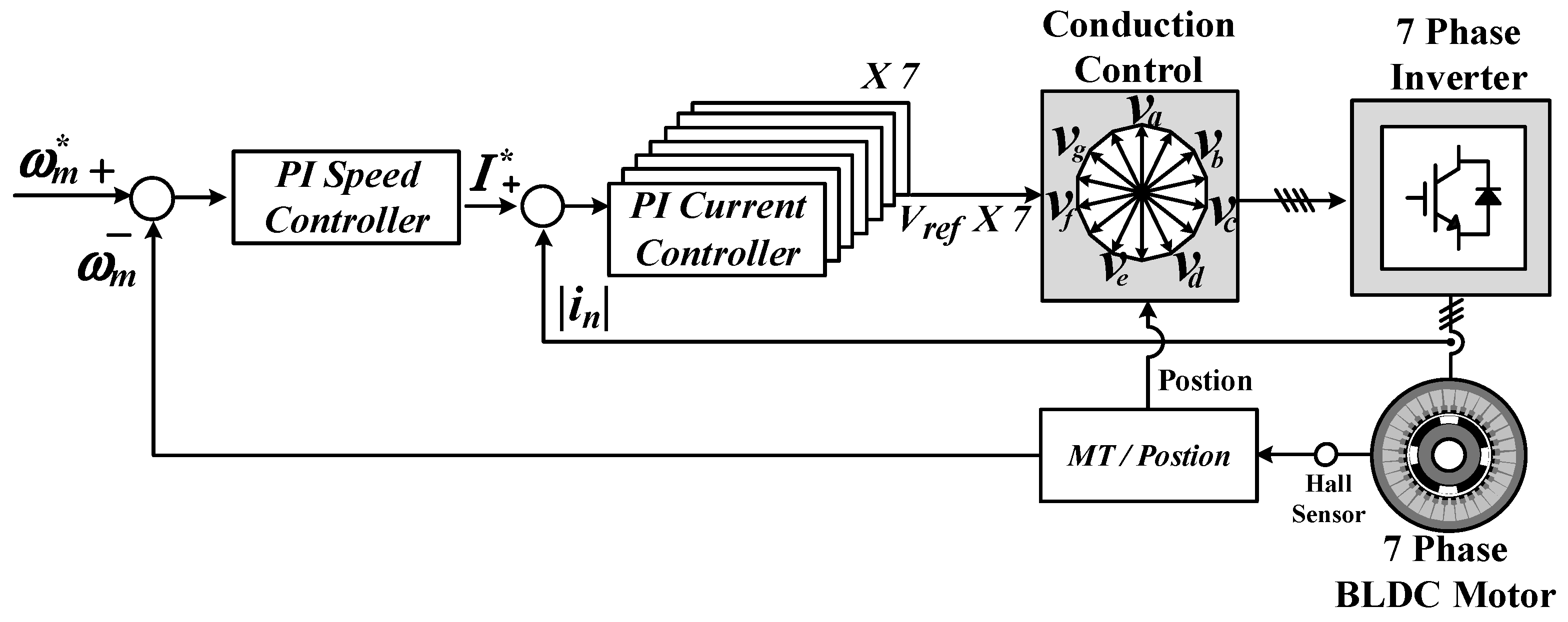
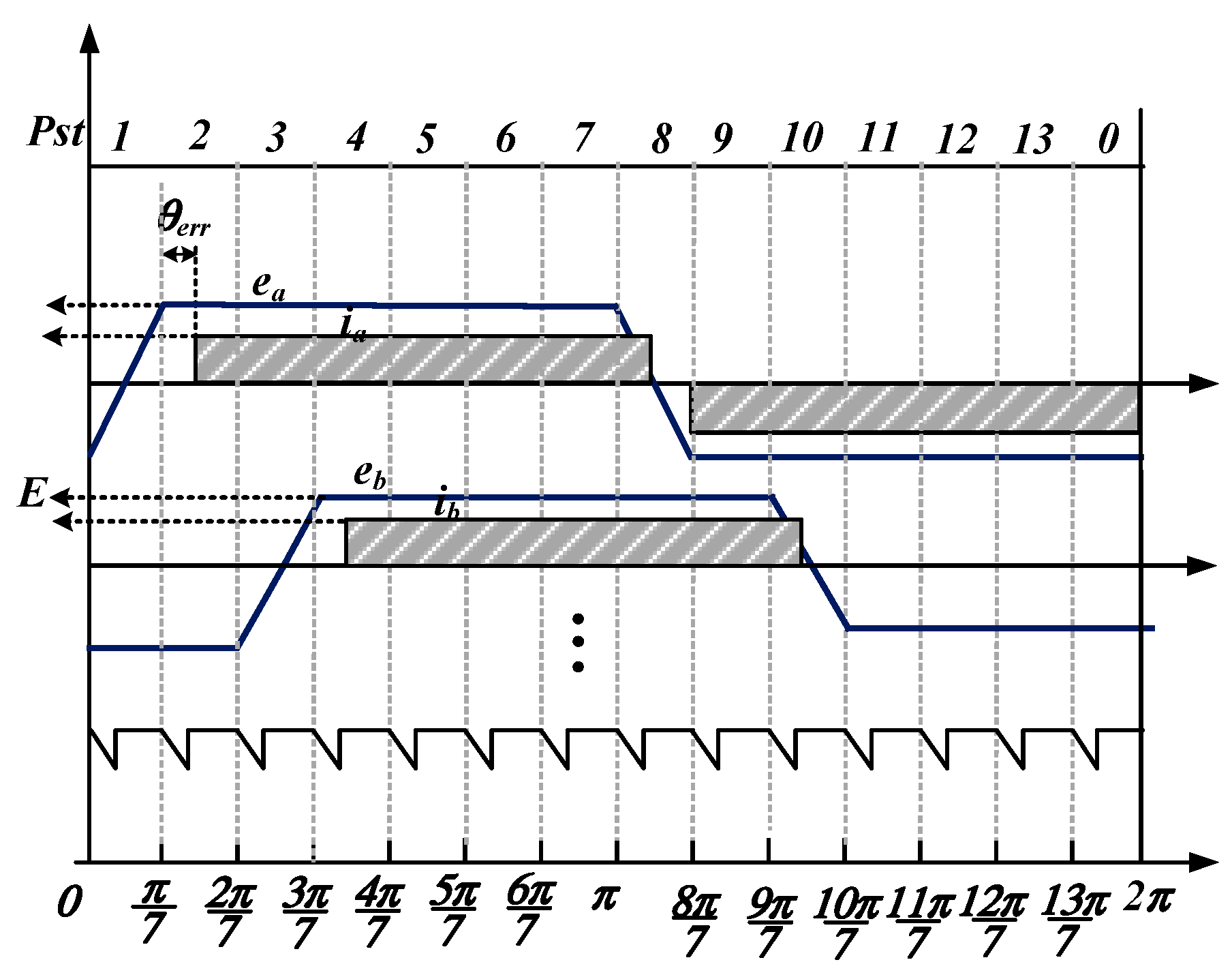
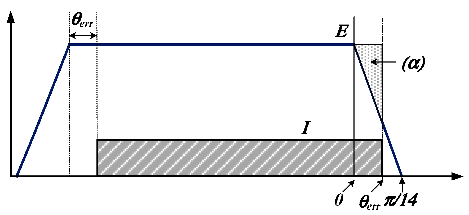
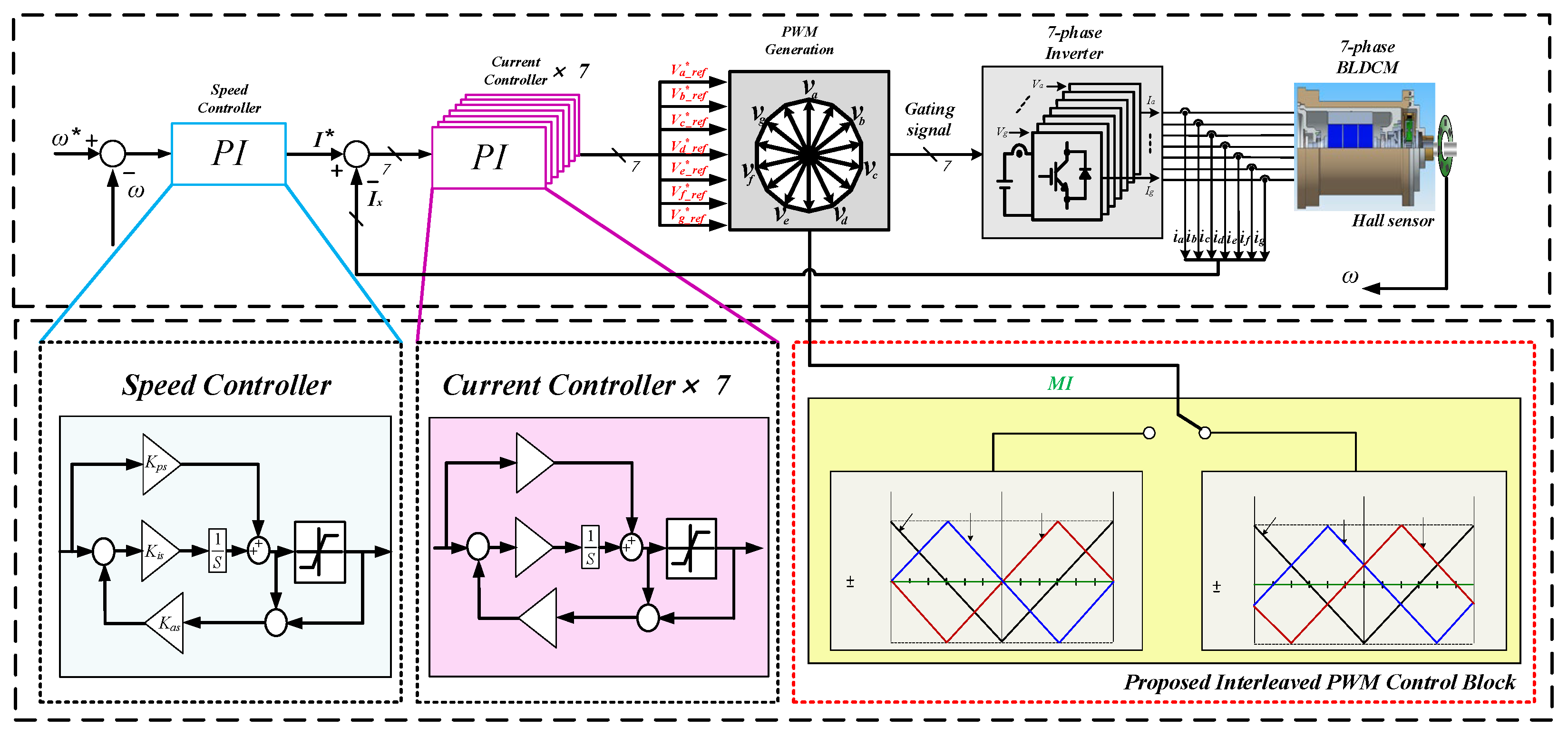
2.2. Basic Control Method

The position of a 7-phase BLDC is divided into fourteen sectors through seven hall sensor signals, as shown in Figure 3. The motor is driven by inducing the square wave current to the stator winding in the section where the back-EMF voltage is flat. There are 2-phase to 7-phase excitation methods depending on the number of excitation windings [9,10]. When the position is a sector 2 in a 6-phase excitation method, “A”, “F”, and “G” phases are positive conduction states; “B”, “C”, and “D” phases are negative conduction states; and “E” phase exists in a non-conduction state. Table 1 provides the conduction states depending on the position in a 6-phase excitation method.
The structure of the controller is shown in Figure 4. To control the current as a square wave, seven current controllers regulate each phase current independently, and the polarity of voltage reference is applied according to the position in Table 1. In this case, the current controller of the non-conductive phase stops the calculation and holds the value. The above control method is particularly easy to implement in fault-tolerance control and hybrid-phase excitation control [25,28,29].

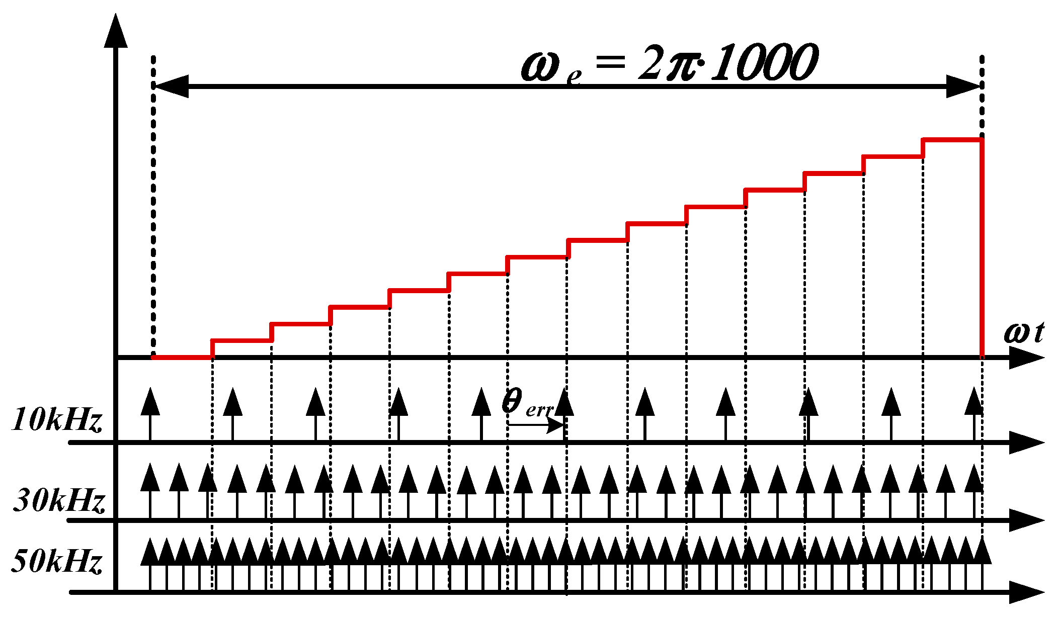
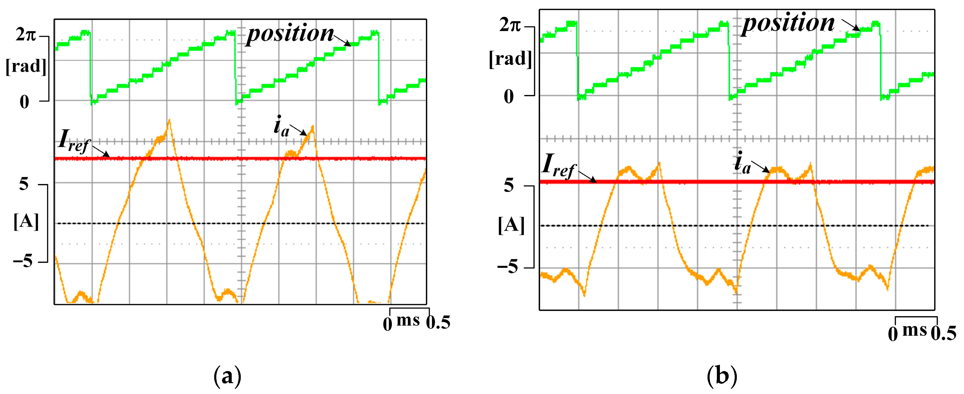
2.3. Control Characteristic according to Switching Frequency

In the seven-phase BLDCM control method, an increase of the switching frequency can have advantages in two ways. First, the ripple of the current can be reduced. It is affective on the high-speed BLDC motor with low inductance. Another advantage is the compensation for position error caused by low resolution in the high-speed region. Figure 5 shows the rotor position resolution depending on the sampling frequency. When the control frequency is 10 kHz, 30 kHz, and 50 kHz, the sampling point of position is expressed. The seven-phase control method divides rotor position in 14 sectors, and the commutation change is conducted in every sector. However, a control frequency of 10 kHz cannot immediately respond to the commutation change; then, the position error ( θ e r r ) is caused by sampling delay. The control frequency of the current controller is also insufficient to control the current reference.
Figure 6 shows the effect of position error. The current of each phase should be induced at the region where the back-EMF voltage is flat. However, the position error causes torque reduction due to the area of the triangle, as expressed as “ α ” in Figure 7. The area “ α ” is proportional to the triangle region of the back-EMF voltage, and the proportional equation can be expressed as Equation (7).
π 14 : E = θ e r r : 14 π E θ e r r
By using (7), the amount of torque reduction ( T l o s s ) can be driven as Equation (8), and output torque of Equation (6) can be expressed as Equation (9) when the position error exists.
T l o s s = 7 π E θ e r r 2
T e = 6 E I 7 π E θ e r r 2 14 ω m
Therefore, in order to improve the control performance in the high-speed region and extend the operation region, the increase of switching frequency is essential. These days, the inverter system using SiC-MOSFET allows the possibility of using high switching frequency. However, it also comes with the problem of the EMI noise. Thus, this paper proposes a common-mode voltage-reduction method that is capable of optimizing the resulting EMI noise.

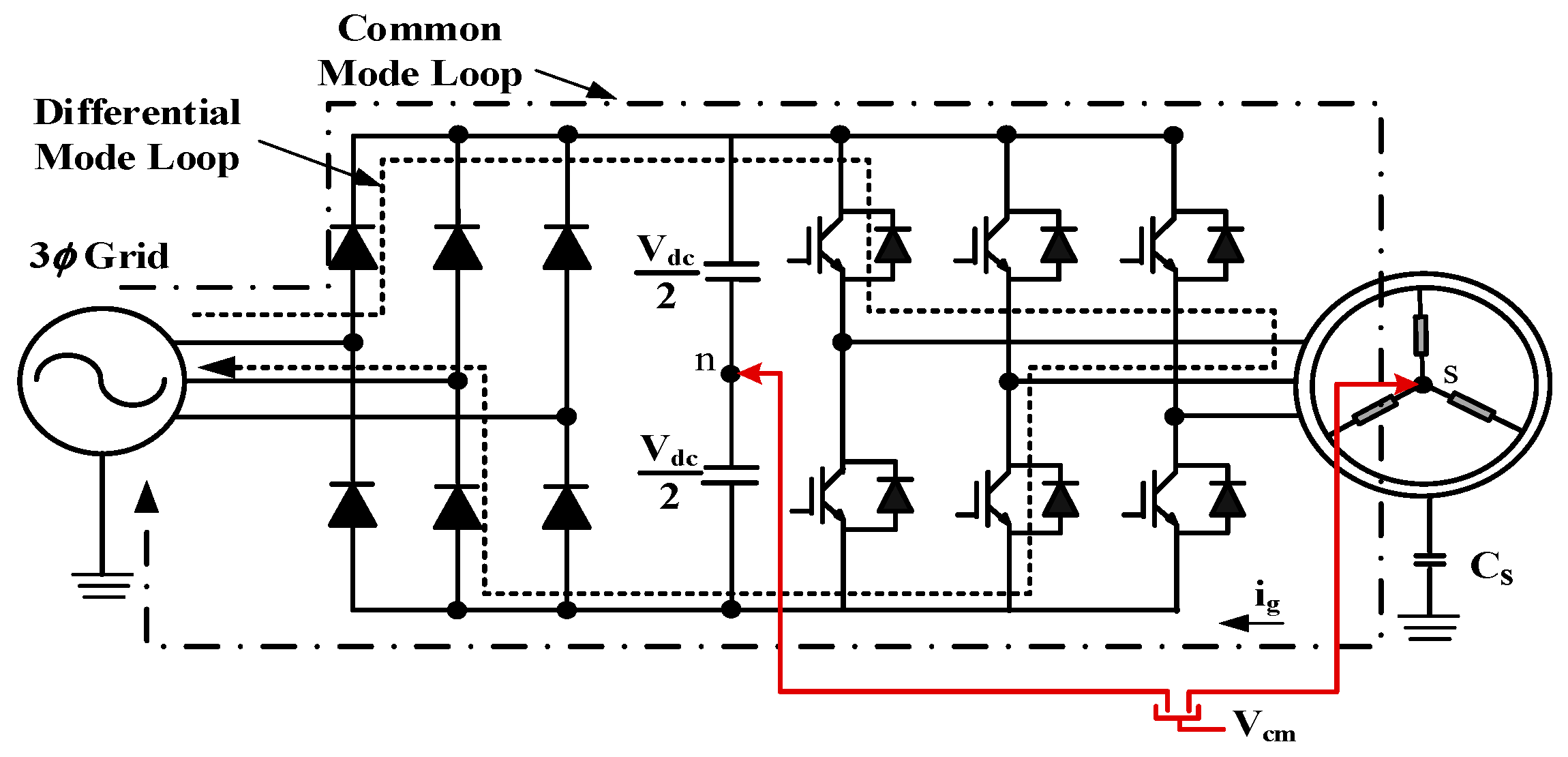
2.4. Description of the Common-Mode Voltage for the 7-Phase BLDC

The modified unipolar PWM method in [33] is used to generate the independent voltage induced to each phase winding, as shown in Figure 8. In this case, all of the voltage references are assumed to be identical for simple description. The positive and negative voltage references formed from current controller of each phase are compared with carrier wave. The positive references decide the on-time of the top switch, which is conducted in the positive conduction phases, and negative references decide the on-time of the bottom switch in the negative conduction phases. This switching method has the advantage of reducing the current pulsation by generating two output voltages in one switching period.
The inverter output voltage including switching function can be expressed as Equation (10), and assuming that the sum of all phase currents and back-EMF are zero, the common-mode voltage can be calculated as Equation (11), where the switching state of non-conduction phase is excluded, and S s t a t e means the number of top switches turned on. Following Equation (11), the kinds of the common-mode voltage ( V c m ) that can be generated in the 6-phase excitation method are expressed as Equation (12). There are seven kinds of voltage that occur according to the switching states.
V x n = ( S x 1 2 ) V d c , S x = { 1 : s w i t c h   o n 0 : s w i t c h   o f f }
V c m = V s n = V d c ( x = a g S x 6 2 ) 6 = V d c ( S s t a t e 3 ) 6
V c m = { V d c 2 , V d c 3 , V d c 6 , 0 , V d c 6 , V d c 3 , V d c 2 }

3. Proposed Phase to Phase Interleaved Method

3.1. Definition of the Phase-Phase Interleaved in the Seven-Phase BLDCM

To reduce the common-mode voltage, the phase shift method in the three-phase inverter is extended to 6-phase excitation method [23]. Three carriers are used, and each carrier is shifted by positive k degrees (“+”) and negative k degrees (“−”) based on the fundamental carrier, as shown in Figure 9. The positive and negative voltage references are, respectively, compared with “ + k ”, “ k ”, and the related carrier. Moreover, the compared carrier should be changed according to the position in the 6-exciation method because the excitation phase is changed in every position. Table 2 shows the matched carrier of each phase according to the position. In Table 2, “ ± k ”and “ 0 ° ”mean the shifted angle of the carrier, and “X” means the non-conductive phase. This arrangement of the carrier waves is intended to minimize the torque ripple due to the phase shift when the position is changed. In Figure 9, the common-mode voltage is shown with a switching state. The generation pattern and magnitude of the common-mode voltage varies depending on the shift angle and MI.

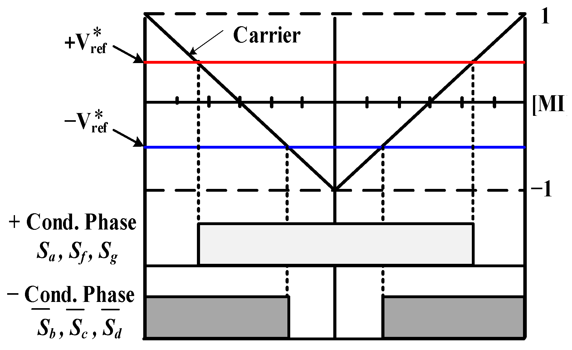
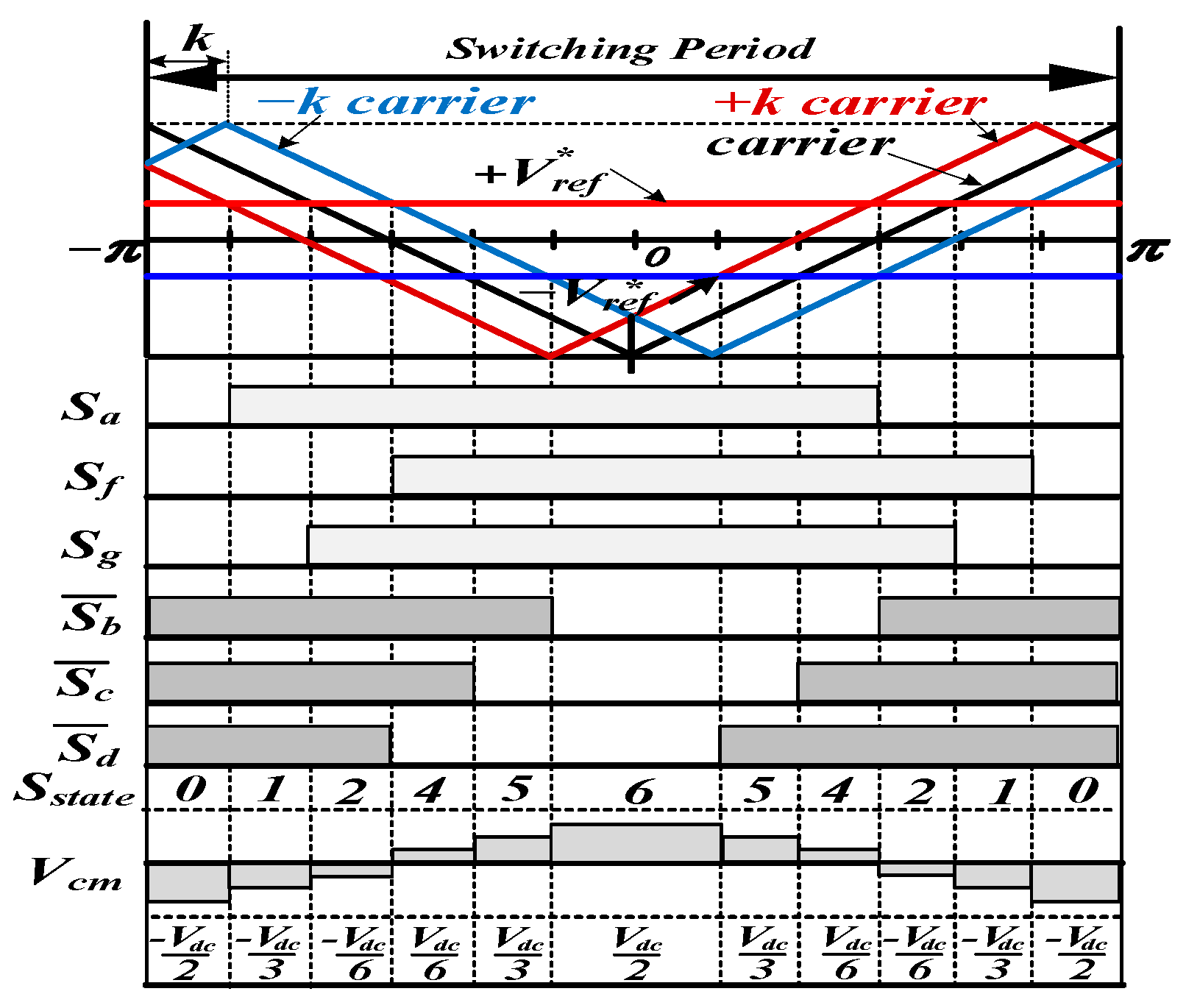
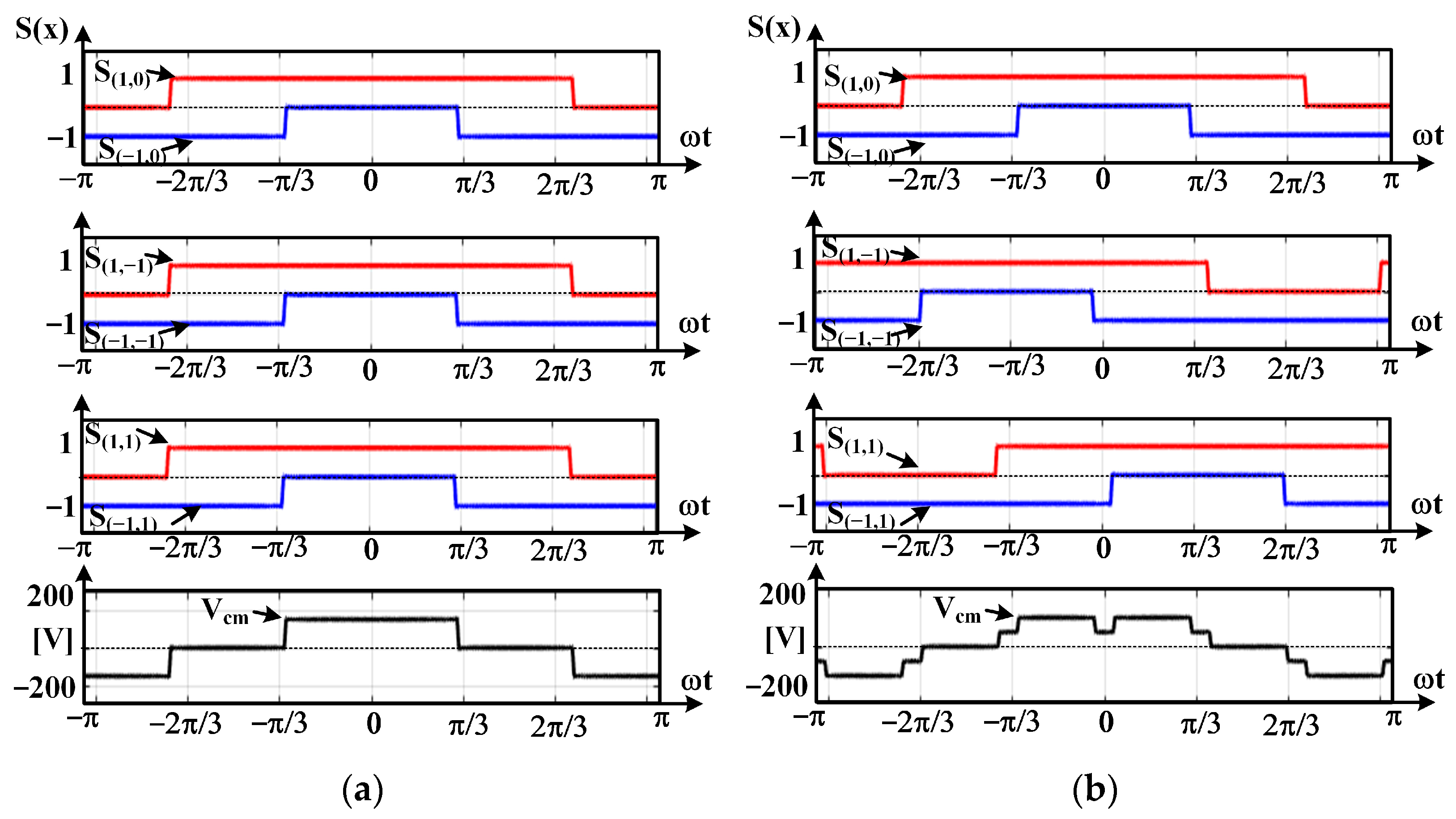
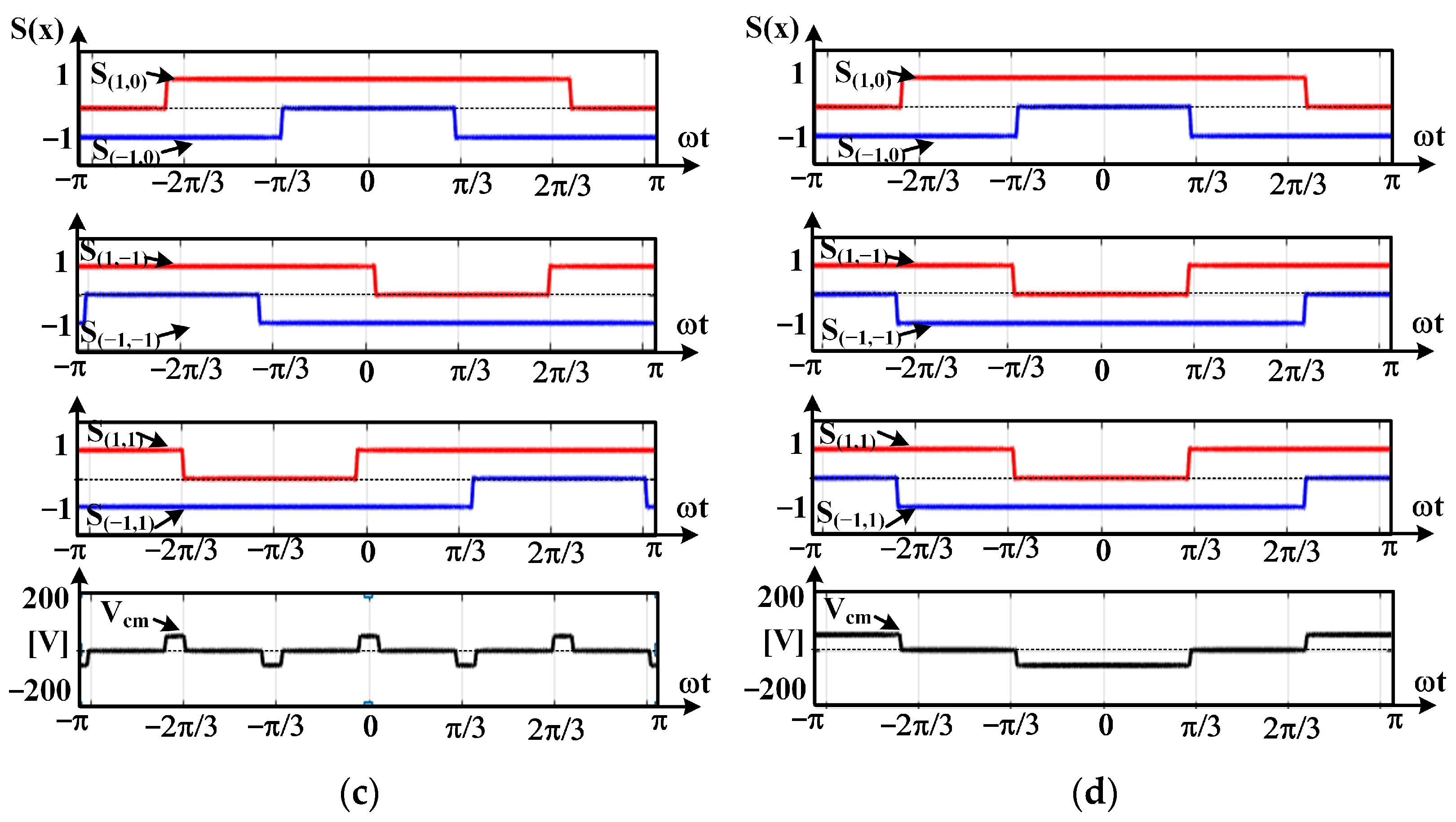
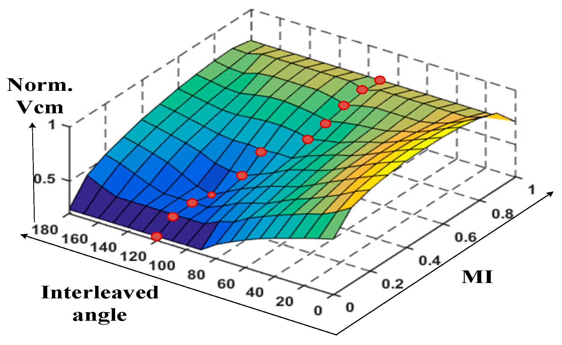
3.2. Switching Function Including the Shift Angle and MI for Minimum Common-Mode Voltage

The switching states of Figure 9 are newly expressed, as shown in Figure 10, to define the switching state based on the compared carrier.
The switching state of x-phase Sx is defined as S(n,m) as in Equation (13). When the top switch is on, n becomes 1, and n becomes −1 when the bottom switch is on; m becomes 0, −1, and +1 according to the sign of the shifted angle of the carrier.
{ S x } { S ( n , m ) }   n = { 1 , 1 } , { 1 :   B o t t o m   s w i t c h   o n + 1 :   T o p   s w i t c h   o n m = { 1 , 0 , 1 } , { 0 : b a s e d c a r r i e r 1 : + k ° s h i f t e d c a r r i e r 1 : k ° s h i f t e d c a r r i e r }
When the phase shift method is applied, the on-off point of each switching state can be expressed as Equation (14), which contains the information of MI and shifting angle ( k ), where θ r e and θ f e are the rising edge and falling edge of the switching state, respectively.
S ( n , m ) [ θ r e , θ f e ] = [ π k m 180 n π 2 ( 1 + n M I ) , π k m 180 + n π 2 ( 1 + n M I ) ]
Since the switching function of equations is a periodic signal, a Fourier series of switching function is driven as Equation (18) by using the Fourier coefficient of Equations (15)–(17), and the effective integration interval is from θ r e to θ f e in Equation (14).
a 0 = 1 π π π f ( x ) d x
a a = 1 π π π f ( x ) cos ( x ) d x
a b = 1 π π π f ( x ) sin ( x ) d x
{ S ( n , m ) ( x ) } = a 0 2 + z = 1 ( a z cos ( z π 2 π x ) + b z sin ( z π 2 π x ) )
where f ( x ) is defined as 1 or −1, which means the on-state of the top and bottom switches, respectively. The range of x is from −π to π, and z represents the precision of the switching signal. If it becomes larger, the signal is closed to the ideal square wave. By solving Equation (18), the new switching functions including the shifting angle and MI in a switching period can be expressed as Equation (19).
S ( n , m ) ( x ) = 1 + M I 2 + n z = 1 2 z π [ cos ( m z k ) sin ( z π ( 1 + n M I ) 2 ) cos ( z x ) sin ( m z k ) sin ( z π ( 1 + n M I ) 2 ) sin ( z x ) ]
At last, the common-mode voltage according to the switching state can be calculated as (20).
V c m = V d c ( S ( 1 , 0 ) ( x ) + S ( 1 , 1 ) ( x ) + S ( 1 , 1 ) ( x ) + S ( 1 , 0 ) ( x ) + S ( 1 , 1 ) ( x ) + S ( 1 , 1 ) ( x ) ) / 6

3.3. Proposed Control Method for Phase Shift in 6-Excitation Method

Figure 11 shows the verification of Equations (19) and (20), which includes the specific shift angle and MI. The equations are programed by using MATLAB. As shown in Figure 10, the common-mode voltage has various patterns according to MI and shift angle. Therefore, the RMS value of V c m is calculated as shown in Equation (21) to find the optimal shift angle with generation of the lowest common-mode voltage.
V c m ( r m s ) = 1 T 0 T V c m 2 d t
Figure 12 shows the normalized RMS value of the common-mode voltage when the conventional PWM without phase shift and phase shift method in specific angles are compared in specific angle. When the MI is lower than 0.5, a 120° shifting angle has the best performance for the generation of common-mode voltage. On the other hand, a 90° shifting angle has the lowest common-mode voltage when the MI is higher than 0.5, and the red dot indicates the point where the common-mode voltage is minimized during the operation in full range.
Figure 13 shows the proposed interleaved method to reduce the common-mode noise in the 7-phase BLDCM operation system. When the MI was smaller than 0.5, a 90 degree interleaved method was adopted, and when the MI was larger than 0.5, a 120 interleaved method was conducted.

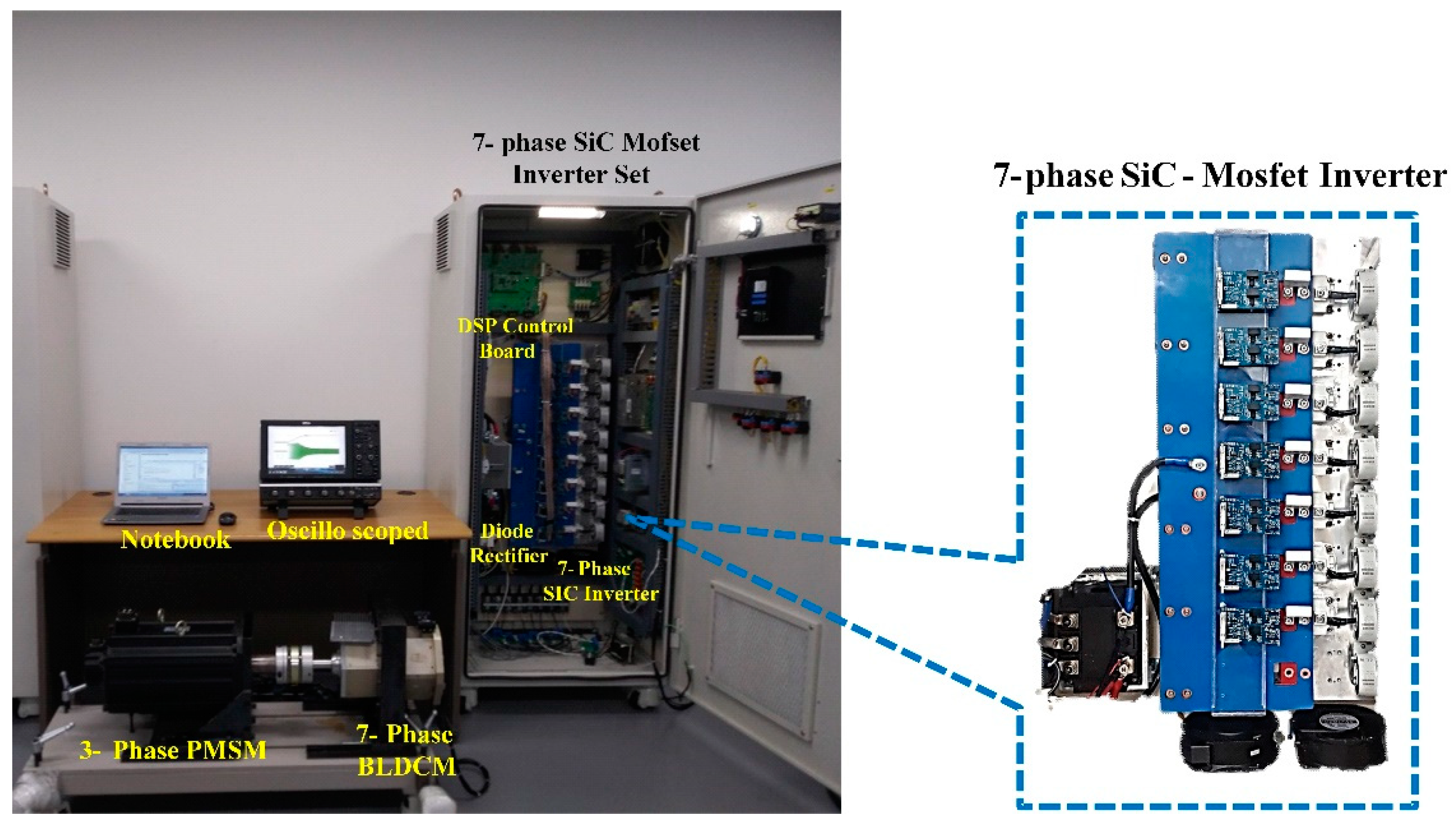
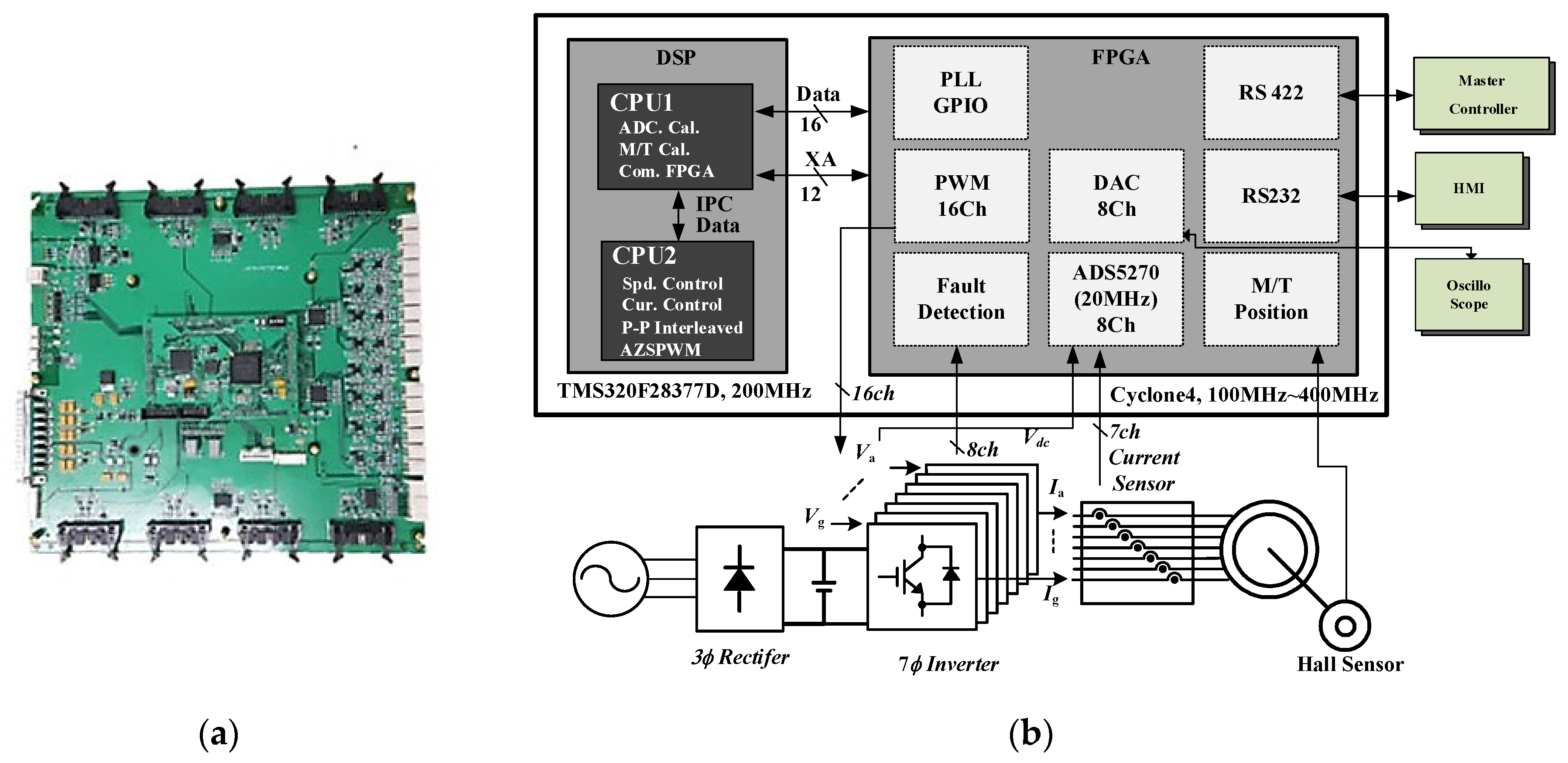
4. Experimental Set-Up and Results

4.1. System Configuration for SiC-MOSFET

Figure 14 shows the experimental set-up using SiC-MOSFET for high-speed control and switching frequency. A 3-phase rectifier, DC-link bank, SiC-MOSFET inverter, and developed control board are integrated in the system. The SIC-MOSFET (CAS300M12BM2) and gate driver (CGD15HB62P1) are made by CREE Inc. The dc-link and motor specification are shown in Table 3. The picture and configuration of the control board are shown in Figure 15. TMS320F28337D (DSP) and Cyclone4 (FPGA) are designed to calculate the control algorithm in 70 kHz. TMS320F28377D has a dual core, so the control algorithm is properly distributed for reducing the calculation time, and a high-speed analog-to-digital converter (ADS5270) is used to remove the sampling delay of the phase current. All of functions to control the motor are implemented in FPGA. It can help to secure the calculation time of DSP.

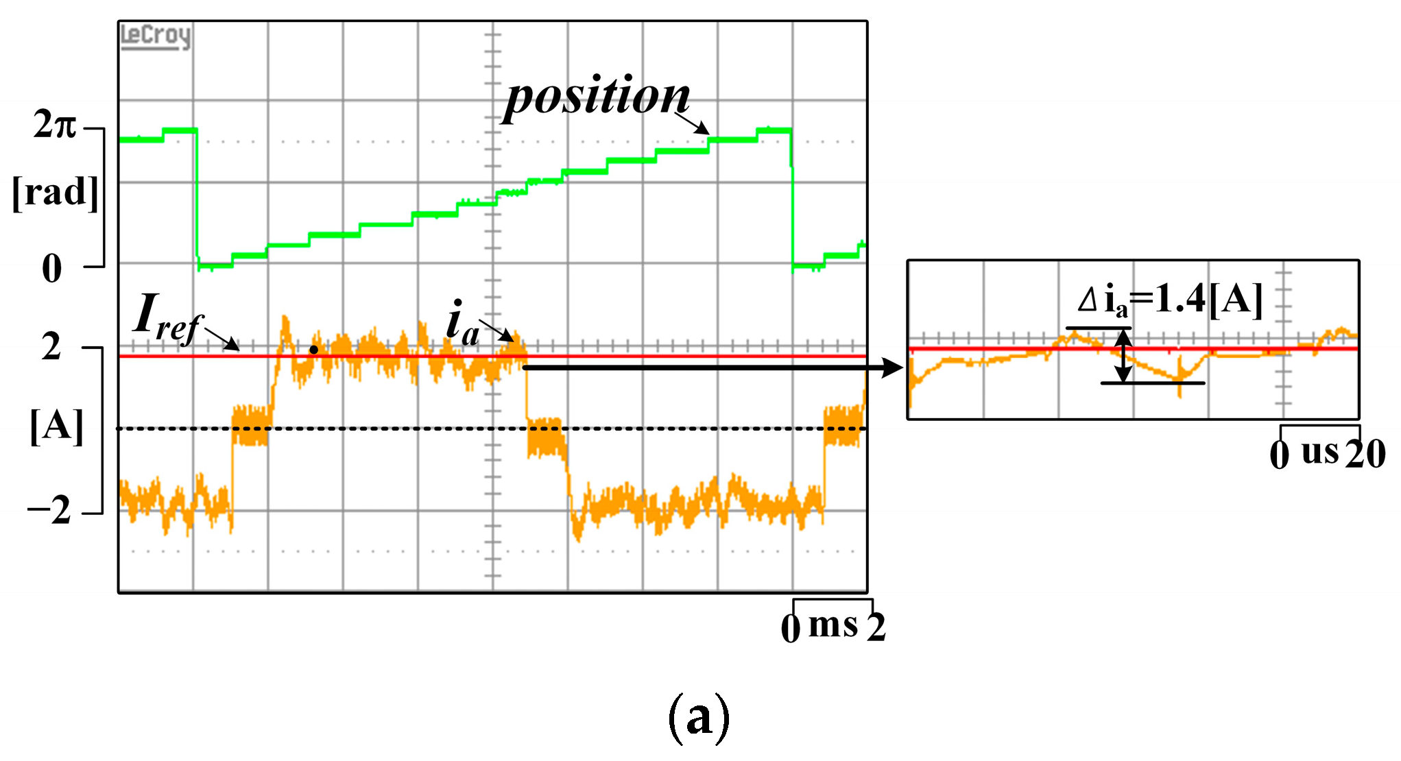
4.2. Control Performance According to Switching Frequency

In order to compare the relationship between the control frequency and control performance, the current control in 10 kHz of the conventional switching frequency is compared with 40 kHz and 70 kHz. Table 4 shows the current control cycle in a specific rotor rotation frequency and switching frequency. We already know that as a control rule, current control is required to operate at least five times within the speed control cycle. Figure 16 shows the 1.8 A current control and the speed of motor is saturated by the mechanical friction. Figure 16a shows the large torque ripple caused by commutation change in the 6-exictation method. If the switching frequency increases to 70 kHz, the torque ripple is reduced. As mentioned earlier, the control frequency affects the position error. Specially, seven-phase BLDCM is controlled by dividing the position to 14 sectors.
Sufficient control frequency is required in every sector. The operation cycle of the current controller can be calculated using Equation (22).
O p e r a t i o n   C y c l e = C o n t r o l   f r e q u e n c y R p m × P 2 × 60 × 14
Figure 17 shows the speed control in 4000 rpm. Speed control in the conventional control frequency of Figure 17a shows a large current ripple caused by commutation change. Increasing the switching frequency improves the control performance through instant sampling of position changes, as shown in Figure 17b,c. In the speed control of 10 (kHz) at 7800 rpm, as shown in Figure 18a, the current cannot be controlled, and the maximum output results. This is due to the lack of frequency of operation of the current controller for one sector, as shown in Table 4, and the sampling error of the position is included. On the other hand, in the speed control of 40 kHz or 70 kHz, the phase current is controlled well.
Figure 19 shows the speed control in 10,400 rpm. In this region, the speed control of 40 kHz cannot control the phase current well. As shown in Figure 17, Figure 18 and Figure 19, increasing the switching frequency affects the improvement of the control performance and extends the operation range. Figure 19 shows the speed control in 10,400 rpm. In this region, the speed control of 40 kHz does not control the phase current well. As shown in Figure 17, Figure 18 and Figure 19, increasing the switching frequency affects the improvement of control performance and extends the operation range.
Figure 20 shows the amount of the common-mode voltage and leakage current when the switching frequency increases. When the switching frequency increased from 14 kHz to 70 kHz, it was confirmed that the common-mode noise increased.

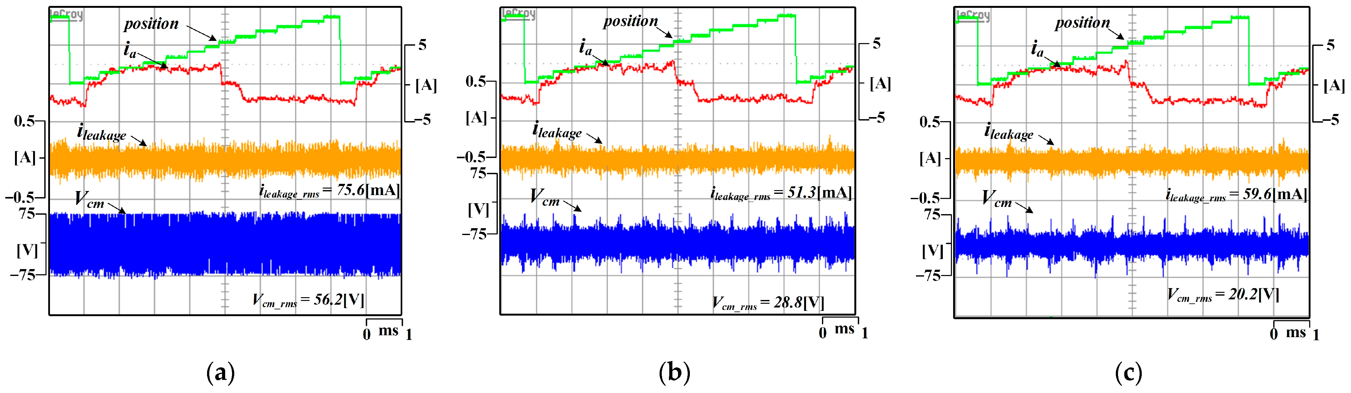
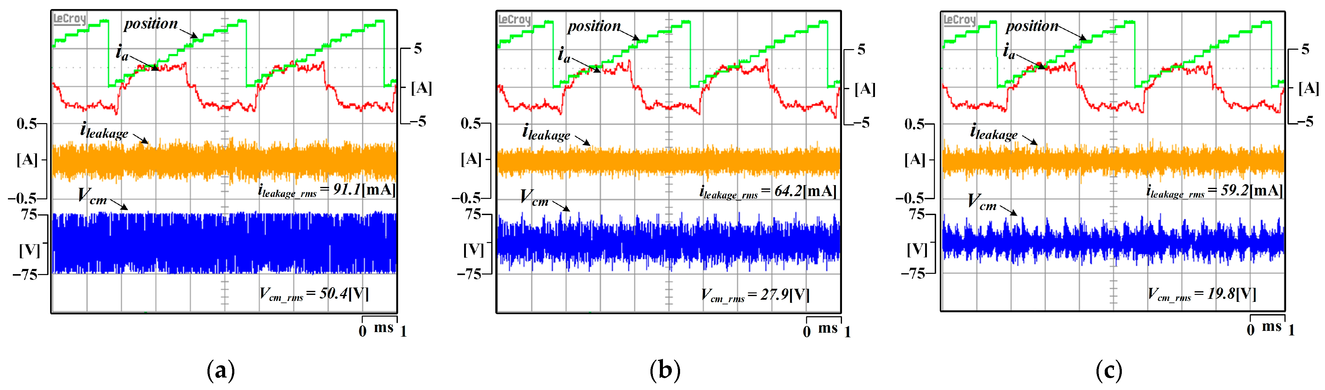
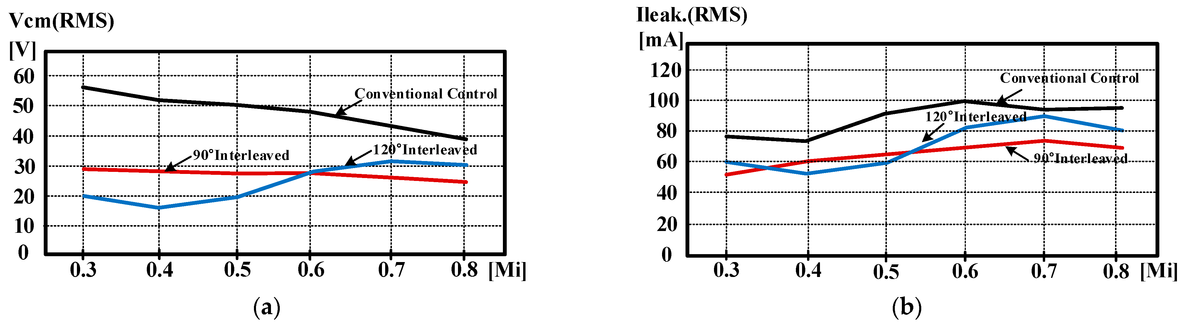
4.3. Common-Mode Voltage Generation According to the Interleaved Method and MI

As we know from the above experiments, increasing the switching frequency is the most important for improving the control performance, but reducing the common monde noise is more important in the current industry. Figure 21 shows the experimental results of the proposed common-mode voltage generation according to the interleaved angle in the no-load condition. The switching frequency is controlled constantly at 40 kHz. The speed control of the 7-phase BLDCM is implemented, and the speed reference is 4000 rpm. Figure 19a shows the conventional 7-phase PWM method, and Figure 21b,c represent the 90° and 120° interleaved methods, respectively. In the no-load condition, where the modulation index (MI) is very low, the conventional PWM method has the largest common-mode voltage, and the smallest common-mode voltage appears when using 120° interleaved method.
The experimental results of the common-mode voltage and leakage current according to the PWM method and MI with the load condition are shown in Figure 22, Figure 23 and Figure 24. The modulation index (MI) is controlled from 0.3 to 0.7 to compare results. It shows the 0.3 modulation index (MI) condition in (a), 0.5 modulation index (MI) condition in (b), and 0.7 modulation index (MI) condition in (c). As presented in Figure 22 and Figure 23, when the modulation index (MI) condition is 0.3 and 0.5, the 120° interleaved method has the smallest common-mode voltage, and conventional 7 phase PWM has the largest common-mode voltage; as presented in Figure 24, for the 0.7 modulation index (MI) condition, the 90° interleaved method has the smallest common-mode voltage, and conventional 7-phase PWM has the largest common-mode voltage. Figure 25 shows the comparison of the common-mode noise between the conventional PMW and interleaved method. There is a little difference from the mathematical analysis due to the independent voltage reference of the 7-phase current controller. In conclusion, as observed in the experimental waveforms, the proposed method of applying the optimal interleaved angle according to MI can reduce the effect of the common-mode voltage by up to 50% compared to the conventional PWM method. Since the optimal interleaved angle is related with the modulation index (MI), a selective control method is required between the 90° interleaved method and 120° interleaved method.

5. Conclusions

This paper presents the relationship between the carrier interleaving method and modulation index (MI) with common-mode voltage in a 7-phase BLDCM control system using SiC-MOSFET for higher switching frequency. Using SiC-MOSFET can reduce current ripple and compensate for position error caused by low resolution in high-speed regions. However, increasing the switching frequency causes common-mode voltage and EMI noise. The implementation of the interleaved method in 6-excitation control is described, in which the amount of common-mode voltage was analyzed because it depends on the interleaved angle and MI. The RMS value of the common-mode voltage in a switching period was derived by mathematical equation. The paper proposes the method that operates the optimal interleaved angle according to MI for minimum common-mode voltage, and experiments about common-mode voltage were conducted to verify the optimal interleaved angle.

Author Contributions

Conceptualization, D.-Y.K. and J.-M.K.; methodology, Y.-D.S.; software, D.-Y.K.; validation, H.-J.K. and J.-M.K.; formal analysis, D.-Y.K. and J.-M.K.; investigation, D.-Y.K.; writing—original draft preparation, Y.-D.S. and H.-J.K.; writing—review and editing, Y.-D.S. and H.-J.K.; visualization, D.-Y.K.; supervision, J.-M.K. All authors have read and agreed to the published version of the manuscript.

Funding

This research received no external funding.

Data Availability Statement

Accepted and complied with.

Acknowledgments

This paper was supported by Education and Research promotion program of KOREATECH in 2022. This work was supported by the Technology Innovation Program-Materials/Parts Technology Development Program 2020 (20013335, Development of 150 kW inverter for high power motor control) funded By the Ministry of Trade, Industry & Energy (MOTIE, Korea).

Conflicts of Interest

The authors declare no conflict of interest.

References

  1. Durán, M.J.; Prieto, J.; Riveros, J.A.; Guzman, H. Space-Vector PWM With Reduced Common-Mode Voltage for Five-Phase Induction Motor Drives. IEEE Trans. Power Electron. 2013, 60, 114–124. [Google Scholar]
  2. Simoes, M.G.; Vieira, P., Jr. A High-Torque Low-Speed Multiphase Brushless Machine A Perspective Application of Electric Vehicles. IEEE Trans. Ind. Electron. 2002, 49, 1154–1164. [Google Scholar]
  3. Gan, J.; Chau, K.T.; Chan, C.C.; Jiang, J.Z. A New Surface-Inset, Permanent-Magnet, Brushless DC Motor Drive for Electric Vehicles. IEEE Trans. Magn. 2000, 36, 3810–3818. [Google Scholar]
  4. Wang, H.; Zheng, X.; Yuan, X.; Wu, X. Enhanced Natural Fault-Tolerant Model Predictive Current Control in Nine-Phase Motor Drives Under Open-Phase Fault. IEEE Trans. Energy Convers. 2022, 37, 2449–2460. [Google Scholar]
  5. Moon, J.J.; Won, L.; Park, S.W.; Kim, J.M. Fault tolerant control method of seven-phase BLDC motor in asymmetric fault condition due to open phase. In Proceedings of the 2015 IEEE International conference on Power Electronics and ECCE Asia, Seoul, Republic of Korea, 1–5 June 2015. [Google Scholar]
  6. Tao, T.; Zhao, W.; Du, Y.; Zhu, Y.C. Simplified fault-tolerant model predictive control for a five-phase permanent-magnet motor with reduced computation burden. IEEE Trans Power Electron. 2022, 35, 3850–3858. [Google Scholar]
  7. Park, J.B.; Johnson, M.; Toliyat, H.A. A Novel Hysteresis Current Control switching Method for Torque Ripple Minimization in Multi-Phase Motors. In Proceedings of the 2014 IEEE Energy Conversion Congress and Exposition (ECCE), Pittsburgh, PA, USA, 14–18 September 2014. [Google Scholar]
  8. Ryu, H.M.; Kim, J.W.; Sul, S.K. Synchronous-frame current control of multiphase synchronous motor under asymmetric fault condition of due to open phases. IEEE Trans. Ind. Appl. 2006, 42, 1062–1070. [Google Scholar]
  9. Park, H.S.; Park, S.W.; Kim, D.Y.; Kim, J.M. Hybrid Phase Excitation Method for Improving Efficiency of 7-Phase BLDC Motors for Ship Propulsion Systems. Trans J. Power Electron. 2019, 19, 761–770. [Google Scholar]
  10. Kim, T.Y.; Lee, B.K.; Won, C.Y. Modeling and simulation of multiphase BLDC motor drive systems for autonomous underwater vehicles. In Proceedings of the 2007 IEEE International Electric Machines & Drives Conference, Antalya, Turkey, 3–5 May 2007. [Google Scholar]
  11. Lee, M.H.; Kim, H.J.; Kim, J.M. Automatic advance angle control algorithm using anti-windup feedback voltage of PI current controller for wide range speed operation of BLDCM. In Proceedings of the 2018 IEEE Applied Power Electronics Conference and Exposition (APEC), San Antonio, TX, USA, 4–8 March 2018. [Google Scholar]
  12. Lai, Y.S.; Chen, J.H. A New Approach to Direct Torque Control of Induction Motor Drives for Constant Inverter Switching Frequency and Torque Ripple Reduction. IEEE Trans. Energy Convers. 2001, 16, 220–227. [Google Scholar]
  13. Agarwal, A.K. An overview of SiC power devices. In Proceedings of the 2010 International Conference on Power, Control and Embedded Systems (ICPCES), Allahabad, India, 29 November–1 December 2010. [Google Scholar]
  14. Lemmon, A.; Mazzola, M.; Gafford, J.; Parker, C. Stability Considerations for Silicon Carbide Field-Effect Transistors. IEEE Trans. Power Electron. 2013, 28, 4453–4459. [Google Scholar]
  15. Xu, F.; Jiang, D.; Wang, J.; Wang, F.; Tobert, L.M.; Han, T.J.; Kim, S.J. Characterization of a high temperature multichip SiC JGET-based module. In Proceedings of the 2011 IEEE Energy Conversion Congress and Exposition, Phoenix, AZ, USA, 17–22 September 2011. [Google Scholar]
  16. Ala, G.; Giaconia, G.C.; Giglia, G.; Piazza, M.C.D.; Vitale, G. Design and Performance Evaluation of a High Power-Density EMI Filter for PWM Inverter-Fed Induction-Motor Drives. IEEE Trans. Ind. Appl. 2016, 52, 2397–2404. [Google Scholar]
  17. Akagi, H.; Hasegawa, H.; Doumoto, T. Design and Performance of a Passive EMI Filter for Use With a Voltage-Source PWM Inverter Having Sinusoidal Output Voltage and Zero Common-Mode Voltage. IEEE Trans. Power Electron. 2004, 19, 1069–1076. [Google Scholar]
  18. Son, Y.C.; Sul, S.K. A New Active Common-Mode EMI Filter for PWM Inverter. IEEE Trans. Power Electron. 2003, 18, 1309–1314. [Google Scholar]
  19. Son, Y.C.; Sul, S.K. Generalization of Active Filters for EMI Reduction and Harmonics Compensation. IEEE Trans. Ind. Appl. 2006, 42, 545–551. [Google Scholar]
  20. Ogasawara, S.; Ayano, H.; Akagi, H. An Active Circuit for Cancellation of Common-Mode Voltage Generated by a PWM Inverter. IEEE Trans. Power Electron. 1998, 13, 835–841. [Google Scholar]
  21. Hou, C.C.; Shih, C.C.; Cheng, P.T.; Hava, A.M. Common-Mode Voltage Reduction Pulse width Modulation Techniques for Three-Phase Grid-Connected Converters. IEEE Trans. Power Electron. 2013, 28, 1971–1979. [Google Scholar]
  22. Hava, A.M.; Un, E. A High-Performance PWM Algorithm of Common-Mode Voltage Reduction in Three-Phase Voltage Reduction in Three-Phase Voltage Source Inverters. IEEE Trans. Power Electron. 2011, 26, 1998–2008. [Google Scholar]
  23. Cacciato, M.; Consoli, A.; Scarcella, G.; Testa, A. Reduction of Common-Mode Currents in PWM Inverter Motor Drives. IEEE Trans. Ind. Appl. 1999, 35, 469–476. [Google Scholar]
  24. Un, E.; Hava, A.M. A Near-State PWM Method With Reduced Switching Losses and Reduced Common-Mode Voltage for Three-Phase Voltage Source Inverters. IEEE Trans. Ind. Appl. 2009, 45, 782–793. [Google Scholar]
  25. Oriti, G.; Julian, A.L.; Lipo, T.A. A New Space Vector Modulation Strategy for Common Mode Voltage Reduction. In Proceedings of the Power Electronics Specialists Conference, St. Louis, MO, USA, 27–27 June 1997. [Google Scholar]
  26. Huang, J.; Shi, H. Reducing the Common-Mode Voltage through Carrier Peak Position Modulation in an SPWM Three-Phase Inverter. IEEE Trans. Power Electron. 2014, 29, 4490–4495. [Google Scholar]
  27. Kim, D.Y.; Ma, J.S.; Kim, J.M. Phase to Phase Interleaved Method to Reduce the Common Mode Voltage for Seven Phase BLDCM Drive. In Proceedings of the 2019 IEEE International conference on Power Electronics and ECCE Asia, Busan, Republic of Korea, 1–7 May 2019. [Google Scholar]
  28. Lee, H.D.; Sul, S.K. Common-Mode Voltage Reduction Method Modifying the Distribution of Zero-Voltage Vector in PWM Converter/Inverter System. IEEE Trans. Ind. Appl. 2001, 37, 1732–1738. [Google Scholar]
  29. Zhang, D.; Wang, F.; Burgos, R.; Lai, R.; Boroyevich, D. DC-Link Ripple Current Reduction for Paralleled Three-Phase Voltage-Source Converters With Interleaving. IEEE Trans. Power Electron. 2011, 26, 1741–1753. [Google Scholar]
  30. Lai, Y.S.; Shyu, F.S. Optimal Common-Mode Voltage Reduction PWM Technique for Inverter Control With Consideration of the Dead-Time Effects-Part I: Basic Development. IEEE Trans. Ind. Appl. 2004, 40, 1605–1612. [Google Scholar]
  31. Quan, Z.; Li, T.W. Impact of PWM Schemes on the Common Mode Voltage of Interleaved Three-Phase Two-Level Voltage Source Converters. IEEE Trans. Ind. Electron. 2019, 66, 852–864. [Google Scholar]
  32. Chen, H.; Zhao, H. Review on pulse-width modulation strategies for common-mode voltage reduction in three-phase voltage-source inverters. IET Power Electron. 2016, 9, 2611–2620. [Google Scholar]
  33. Kim, H.W.; Shin, H.K.; Mok, H.S.; Lee, Y.K.; Cho, H.Y. Novel PWM Method with Low Ripple Current for Position Control Applications of BLDC Motor. J. Power Electron. 2011, 11, 726–733. [Google Scholar]
Figure 1. Loop of conduction noise in the motor drive system.
Energies 16 02097 g001
Figure 2. Equivalent model of 7-phase inverter system.
Energies 16 02097 g002
Figure 3. Excitation method of 7-phase BLDC motor.
Energies 16 02097 g003
Figure 4. Structure of controller for driving 7-phase BLDC motor.
Energies 16 02097 g004
Figure 5. Rotor position resolution depending on the sampling frequency.
Energies 16 02097 g005
Figure 6. Torque ripple caused by position error.
Energies 16 02097 g006
Figure 7. Torque error caused by position error.
Energies 16 02097 g007
Figure 8. Modified unipolar PWM method in BLDC control.
Energies 16 02097 g008
Figure 9. Switching state and common-mode voltage of phase-phase interleaved method.
Energies 16 02097 g009
Figure 10. Revised switching state of phase-phase interleaved method in 7-phase BLDCM.
Energies 16 02097 g010
Figure 11. Pattern of common-mode voltage depending on the shift angle and MI: (a) k = 0°, MI = 0.4; (b) k = 60°, MI = 0.4; (c) k = 120°, MI = 0.4; and (d) k = 180°, MI = 0.4.
Energies 16 02097 g011aEnergies 16 02097 g011b
Figure 12. Amount of common-mode voltage depending on the interleave angle and MI.
Energies 16 02097 g012
Figure 13. Proposed phase interleaved method to reduce the common-mode noise in the 7-phase BLDCM.
Energies 16 02097 g013
Figure 14. Experimental Configuration of SiC Inverter for 7-phase motor.
Energies 16 02097 g014
Figure 15. Configuration of SiC-MOSFET control board: (a) developed 7-phase control board; (b) block diagram of control board.
Energies 16 02097 g015
Figure 16. Comparison of current control depending on the control frequency: (a) 10 kHz current control; (b) 40 kHz current control; and (c) 70 kHz current control.
Energies 16 02097 g016aEnergies 16 02097 g016b
Figure 17. Speed control characteristic according to switching frequency (4000 rpm); (a) 10 kHz switching frequency; (b) 40 kHz switching frequency; and (c) 70 kHz switching frequency.
Energies 16 02097 g017
Figure 18. Speed control characteristic according to switching frequency (7800 rpm); (a) 10 kHz switching frequency; (b) 40 kHz switching frequency; and (c) 70 kHz switching frequency.
Energies 16 02097 g018
Figure 19. Speed control characteristic According to switching frequency (10,400 rpm); (a) 40 kHz switching frequency; and (b) 70 kHz switching frequency.
Energies 16 02097 g019
Figure 20. Relationship between switching frequency and common noise; (a) 14 kHz switching frequency at 4000 rpm; (b) 40 kHz switching frequency at 4000 rpm; and (c) 70 kHz switching frequency at 4000 rpm.
Energies 16 02097 g020
Figure 21. Comparison of common-mode voltage and leakage current depending on the 40 kHz switching frequency (4000 rpm): (a) conventional 7-phase PWM; (b) 90° interleaved method; and (c) 120° interleaved method.
Energies 16 02097 g021
Figure 22. EMI noise characteristic according to 0.3 MI (2600 rpm) and interleaved method: (a) conventional 7-phase PWM; (b) 90° interleaved method; and (c) 120° interleaved method.
Energies 16 02097 g022
Figure 23. EMI noise characteristic according to 0.5 MI (5000 rpm) and interleaved method: (a) conventional 7-phase PWM; (b) 90° interleaved method; and (c) 120° interleaved method.
Energies 16 02097 g023
Figure 24. EMI noise characteristic according to 0.7 MI (7400 rpm) and interleaved method: (a) conventional 7-phase PWM; (b) 90° interleaved method; and (c) 120° interleaved method.
Energies 16 02097 g024
Figure 25. Common-mode noise comparison according to MI between conventional method and proposed interleaved method: (a) common-mode voltage and (b) leakage current.
Energies 16 02097 g025
Table 1. Definition of conduction phase current according to 6-phase excitation method.
PositionPhase Current
iaibicidieifig
00+++
10+++
2+0++
3+0++
4++0+
5++0+
6+++0
7+++0
80+++
9+++0
100+++
11+++0
120+++
13+++0
Table 2. Compared carrier depending on the position.
PositionPhase
abcdefg
0k+kXk+k
1Xk+kk+k
2+kk+kXk
3+kXk+kk
4+kk+kXk
5+kXk+kk
6k+kk+kX
7k+kXk+k
8Xk+kk+k
9+kk+kXk
10+kXk+kk
11+kk+kXk
12+kXk+kk
13k+kk+kX
Table 3. Parameters for the experiment.
SiC-MOSFET
Inverter
Part numberCAS300M12BM2 (Cree)
Rated Voltage1200 (V)
Rated Current300 (A)
Esw12 (mJ)
Rds(on)4.2 (mΩ)
Switching frequency10~70 (kHz)
DC-Link BankCapacitance1100 (μF)
Voltage150 (V)
Seven-Phase
BLDCM
Pole6
Rated speed7000 (Rpm)
Rated current10 (A)
Stator resistance0.1 (Ω)
Stator Inductance1 (mH)
Back-EMF constant7.5 (V/krpm)
Table 4. Operation cycle according to control frequency and rpm.
RpmFrequency
10 (kHz)40 (kHz)70 (kHz)
4000 (Rpm)3.5 cycle14.2 cycle25 cycle
7800 (Rpm)1.8 cycle7.3 cycle12.8 cycle
10,400 (Rpm)1.3 cycle5.4 cycle9.6 cycle
Disclaimer/Publisher’s Note: The statements, opinions and data contained in all publications are solely those of the individual author(s) and contributor(s) and not of MDPI and/or the editor(s). MDPI and/or the editor(s) disclaim responsibility for any injury to people or property resulting from any ideas, methods, instructions or products referred to in the content.

