Abstract
Fuel cells, as key carriers for hydrogen energy development and utilization, provide a vital opportunity to achieve zero-emission energy use and have thus attracted considerable attention from fundamental research to industrial application levels. Considering the current status of fuel cell technology and the industry, this paper presents a systematic elaboration of progress and development trends in fuel cell core components and key materials, such as stacks, bipolar plates, membrane electrodes, proton exchange membranes, catalysts, gas diffusion layers, air compressors, and hydrogen circulation systems. In addition, some proposals for the development of fuel cell vehicles in China are presented, based on the analysis of current supporting policies, standards, and regulations, along with manufacturing costs in China. The fuel cell industry of China is still in the budding stage of development and thus suffers some challenges, such as lagging fundamental systems, imperfect standards and regulations, high product costs, and uncertain technical safety and stability levels. Therefore, to accelerate the development of the hydrogen energy and fuel cell vehicle industry, it is an urgent need to establish a complete supporting policy system, accelerate technical breakthroughs, transformations, and applications of key materials and core components, and reduce the cost of hydrogen use.
1. Introduction
As an important energy storage method, hydrogen energy is an ideal medium for collaborative optimization across energy networks [1]. Compared with renewable energy, such as wind energy and solar energy, which are unstable and intermittent during generation, hydrogen-based fuel cell techniques are much simpler since there is no need to employ additional energy storage systems to improve the utilization rate and stability [2]. The importance of the development of the hydrogen energy and fuel cell vehicle industry has been stressed in many countries, with appropriate strategies formulated to achieve energy transformation and economic growth. In March 2019, the Ministry of Economy, Trade, and Industry (METI) of Japan released a new version of their Strategic Road Map for the Hydrogen and Fuel Cells label, with the goals of commercialization of fuel cells in the areas of household energy generation and automobile travel by 2025, achieving ownership of 800,000 fuel cell vehicles by 2030, and the establishment of a hydrogen company with universal access to fuel cell vehicles by the year 2050 [3]. Japan has sold a total of 6755 fuel cell vehicles by the end of 2021, as presented in Figure 1. In January 2019, the Hydrogen Economy Roadmap was issued by the government of the Republic of Korea. A total of 6.2 million fuel cell vehicles were expected to be produced by 2040, including 2.9 million for the domestic market and 3.3 million for export, including cars, buses, taxis, and trucks powered by hydrogen fuel cells. In addition, it was expected that the number of hydrogen filling stations would increase to 1200. The Republic of Korea ranked first globally in cumulative sales of fuel cell vehicles by the end of 2021 with sales of 19,374 fuel cell vehicles as shown in Figure 1. The US Fuel Cell and Hydrogen Energy Association (FCHEA) released a new version of the US Hydrogen Road Map in January 2020, with a proposal to sell 150,000 and 1.2 million fuel cell vehicles and to build 1000 and 4300 hydrogen fueling stations by 2025 and 2030, respectively, as a result. The US has sold a total of 12,206 fuel cell vehicles by the end of 2021, as shown in Figure 1. The Fuel Cells and Hydrogen Joint Undertaking (FCH-JU) was the first company to release the Hydrogen Roadmap Europe in February 2019, with a plan to reach a capacity of 45 million passenger fuel cell vehicles, 6.5 million light commercial vehicles, 250,000 fuel cell buses, 1.7 million fuel cell trucks, and 5500 fuel cell trains by the year 2050. The plan called for 15,000 hydrogen refueling stations in Europe by 2040 [4]. As shown in Figure 1, the cumulative sales of fuel cell vehicles in Germany, the Netherlands, and France were 961, 448, and 341, respectively, at the end of 2021.
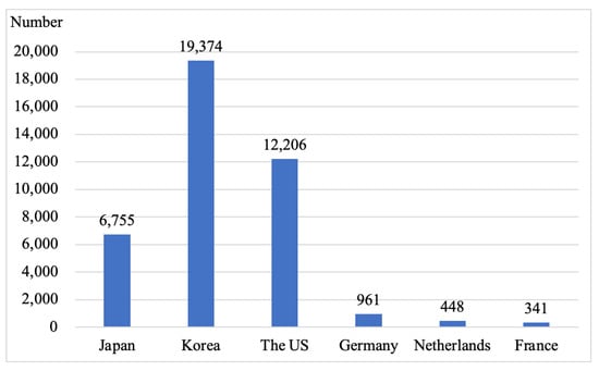
Figure 1.
The cumulative sales of fuel cell vehicles.
The fuel cell vehicle, an important technical approach to new energy vehicles [5,6,7], exhibits characteristics such as excellent environmental performance, high conversion efficiency, short refueling time, long range, and good load performance. It has demonstrated obvious advantages in long-distance and heavy-load conditions and can act as a better alternative to complete electric vehicles [8,9,10].
In addition, China has focused on the development of the fuel cell vehicle industry and has issued a series of supporting policies over the past few years. The Energy-Saving and New Energy Vehicle Technology Roadmap 2.0 was released to the public in October 2020, suggesting the commercialization of fuel cell vehicles prior to 2035 and reaching approximately one million fuel cell vehicle holdings in China [11]. In August 2021, the Chinese government officially launched the pilot application for fuel cell vehicles [12], shifting from the subsidy policy for the purchase of fuel cell vehicles to the support policy for the pilot application of fuel cell vehicles. Within this framework, the qualified city clusters would be rewarded for industrializing key core technologies and demonstrating applications of fuel cell vehicles. The policy also specified that industrial breakthroughs in product research and development (R&D) would be awarded points in the following eight fields: fuel cell stack, membrane electrode assembly (MEA), bipolar plate (BPP), proton exchange membrane (PEM), catalyst layer (CL), carbon paper, compressor, and hydrogen circulation system.
China has established a preliminary industrial chain assembling the fuel cell system, its key components, and the supply of hydrogen energy. Major vehicle enterprises such as FOTON, MAXUS, FEICHI TECHNOLOGY, and YUTONG, and key parts manufacturers with leading technologies like SHPT, FTXT, and REFIRE have emerged in the Beijing–Tianjin–Hebei Region, Yangtze River Delta, Pearl River Delta, and Central China, forming relatively complete industrial clusters. The development of China’s fuel cell vehicle industry continues to accelerate with the strong support of national policies and technological progress. According to the statistics of the China Association of Automobile Manufacturers, the cumulative number of insured fuel cell vehicles reached 8602 as of December 2021, as presented in Figure 2.
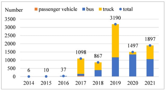
Figure 2.
Annual number of insured fuel cell vehicles in China.
However, China’s fuel cell vehicle industry is still in the early stages with some common issues in the research and development of fuel cells, and their large-scale production and application, and supporting the management of hydrogen refueling infrastructures. Further, a gap still exists between China’s fuel cell vehicle products and the international advanced standards in terms of performance, service life, and reliability. In addition, key fuel cell materials, such as PEM, CL, and carbon paper, are mostly in the sample stage in China; thus, the country heavily depends on imports.
In this study, we focus on the technical development and industrial status of the eight key parts of fuel cells, namely proton exchange membrane fuel cell (PEMFC) stack, MEA, BPP, PEM, CL, gas diffusion layer (GDL), compressor, and hydrogen circulation system. A meticulous analysis of the fuel cell engineering development trend was conducted, and the problems encountered during fuel cell development were summarized. Finally, supporting measures and suggestions were provided as the fundamental reference for the development of the fuel cell industry.
2. An Overview of the Technology and Industry Development of Key Parts of Fuel Cell Vehicles
2.1. Stack
The PEMFC stack is the place of electrochemical reaction and is the core part of hydrogen fuel cell systems, which sustains the energy output of the whole fuel cell system. Generally, the working voltage of a single fuel cell is set to 0.5–1.0 V. To meet the voltage and power requirements in applications, a series of multiple single cells are connected to form a PEMFC stack [13]. A fuel cell stack is composed of alternately stacked MEA, BPP, and seals with current collectors and end plates installed at both ends under a given pressure, as presented in Figure 3 [14].
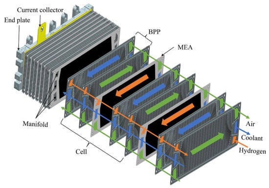
Figure 3.
Basic structure of a typical integrating PEMFC stack [14].
The PEMFC stack has obvious advantages such as pollution-free and high energy density. Unfortunately, its low efficiency and durability and unsatisfactory reliability are the major issues, especially in the high-power scenario [15]. In the aspect of the high reliability of the design method of the high power stack, the core technology of the stack design can be achieved through a large area complex flow field design, highly reliable sealing material and structure design, error analysis, and tolerance design; in the aspect of manufacturing, high consistency of the metal sheet stack assembly can be achieved by using the stacking technology of high consistency of laminated structure and batch manufacturing of efficient flexible production lines.
Apart from China, PEMFC stack enterprises are mostly located in Japan, the Republic of Korea, Europe, and the US. The majority of Japanese and Korean manufacturers, such as Toyota, Honda, and Hyundai, develop their own stacks, while many European and American manufacturers purchase the stacks from cooperative enterprises. For instance, Audi employs customized stacks from Ballard of Canada, and Mercedes Benz uses stacks from AFCC, a joint venture of Mercedes Benz and FOTON.
In China, there are two types of stack enterprises. One resorts to independent R&D, exemplified by SHPT and SinoFuelCell. Sinosynergy and WEICHAI represent the second type, which introduces established stack technology from abroad. The stacks can be categorized into graphite plate stacks, composite plate stacks, and metal plate stacks. Currently, more than 80% of the market in China is occupied by graphite plate stacks and composite plate stacks, while metal plate stacks are gaining a market share year by year.
China’s stack technology has advanced rapidly, and its ability to conduct independent R&D is gradually strengthened. The parameters such as rated power, bulk power density, and cold start temperature of a single stack have been considerably enhanced. Table 1 lists the main technical parameters of the existing products from some Chinese stack enterprises, including power level, power density, cold start temperature, and service life. The performance parameter mentioned in the table is just one of the offerings from the mentioned companies and they have more versions in their portfolio. The stack power has apparently been increased to 200 kW, the bulk power density has reached 6.0 kW/L, and the cold start temperature has been reduced to −40 °C. However, the durability of the stack needs to be verified.

Table 1.
Comparison of stack technology levels of some Chinese stack enterprises.
2.2. Bipolar Plate
One of the core components of the PEMFC is BPP, which accounts for about 80% of the mass, 14–38% of the cost, and almost all the volume of a fuel cell stack [16,17,18,19,20,21,22,23]. The BPP should complete the following functions: separating the fuel, oxidant, coolant and reaction products, ensuring the electrical connection between single cells, providing channels for anode and cathode reaction gases, resisting corrosion under the PEMFC working environment, dissipating heat, and discharging reactant water [24,25]. The technical targets for BPPs were given by the U. S. Department of Energy (DOE) in 2008 [26], as shown in Table 2. Currently, the key problem in bipolar plate materials is how to achieve a reasonable match between the conductivity and corrosion resistance of the coating materials, i.e., to achieve a high corrosion resistance and to ensure the lifetime of the whole system on the assumption of a reasonable conductivity.
Table 2.
Technical targets for BPP.
The BPP of hydrogen fuel cells are available in three different materials on the market, graphite, metal, and composite [25,27]. Graphite is the earliest and most widely used BPP material, exhibiting excellent chemical stability in fuel cell environments [28,29]. The graphite BPP technology has been evolved, commercialized, and is now being applied on a large scale. However, graphite exhibits high porosity, low mechanical strength, and high brittleness. Therefore, a graphite BPP needs to be typically thick to prevent the penetration of working gas and meet the requirement of required mechanical properties, resulting in a large volume and mass. In addition, the poor processing performance and low yield of graphite have substantially increased the manufacturing cost. Although graphite BPP with improved mechanical properties and reduced costs have been realized recently [30,31,32], they still fail to meet the requirements of BPP and are thus seriously limited in applications.
Metals can be easily processed into extremely thin PEMFC BPP (0.1–0.3 mm) and offer several advantages, such as high strength, excellent toughness, good thermal conductivity, and low cost BPP [33,34]. The PEMFC is most effective in acidic (pH 2–3), warm (60–80 °C), and humid environments [35]. The metal bipolar plate stack has the advantages of high power density, fast cold start and good seismic performance, and is suitable for mass production of high-power stacks above 100kW.
In general, various operating conditions (start/stop, idling, and dynamic load, etc.) of the fuel cell electric vehicle can lead to voltage changes [36]. Under such irregular voltage variations, harsh environments, and long-term exposure to corrosive electrolytes, metal BPP can be seriously corroded. Moreover, some metal BPP can form an oxide layer in the PEMFC environment, significantly increasing the interfacial contact resistance (ICR) between the metal BPP and GDL [37]. Metal ions produced by metal corrosion can poison the MEA and reduce fuel cell efficiency [38]. Therefore, surface modification of metal BPP becomes essential to resist the corrosive environments of fuel cells. Ample research has been conducted on modification of metal surfaces, including stainless steel (SS) [39], aluminum (Al) [40], copper (Cu) [41], titanium (Ti) [42], and nickel (Ni) [43]. Interestingly, these surface-modified metals have exhibited better corrosion resistance and lower ICR than those of uncoated metals.
The composite BPP is composed of two or more materials, exhibiting the synergistic effect of corrosion resistance of graphite and high strength of metals, thereby optimizing the mechanical properties. These composite BPP can be either carbon-based or metal-based. Carbon-based composite BPP can be easily mass-produced by molding or the injection molding process, and specifically, their conductivity and mechanical strength can be adjusted by changing the conductive filler to resin ratio. The carbon-based BPP can reduce the manufacturing cost and has emerged as a key development approach. The research community is striving to explore ideal composite BPP with high conductivity and excellent mechanical strength by selecting appropriate conductive fillers and resins, improving the uniformity of mixed carbon materials and resins, and optimizing the preparation process [44,45]. Metal-based composite BPP combine the advantages of graphite BPP and metal BPP and thus can be applied in harsh conditions such as high corrosion resistance, high conductivity, and high strength [46]. However, metal-based composite BPP are difficult to mass-produce because of the complex structure and preparation process, increasing the manufacturing cost.
Well-known BPP manufacturers outside China include Graftech, Dana, POCO, and Treadstone in the US, Siemens and Grabener in Germany, Bac2 in the United Kingdom, and Cellimpact in Sweden. China has developed sophisticated BPP production techniques for mass production and has managed to achieve multiple key technical indexes equivalent to those abroad. At present, the thickness of graphite BPP is generally 0.7 mm. The thickness of metal BPP is generally 0.1 mm. However, China needs to focus on reducing the thickness of BPP and the production of basic materials for metal BPP.
2.3. Membrane Electrode Assembly
The MEA is the most critical component of the fuel cell, which acts as the three-phase material transfer interface and the electrochemical reaction site [47,48]. The MEA mainly consists of the GDL, CL, and proton exchange membrane (PEM), as displayed in the structural diagram (Figure 4). The cathode and anode CLs are separated by PEM, which provides a proton transfer channel from anode to cathode. In addition, PEM also serves to separate the reaction gases, hydrogen, and air in anodic and cathodic compartments, respectively. Hydrogen is oxidized in the anode CL, while oxygen is reduced in the cathode CL. The GDL, on the other hand, is in direct contact with the flow channel on the BPP to mechanically support electron conduction, diffuse reaction gas, and drain water [49,50,51].
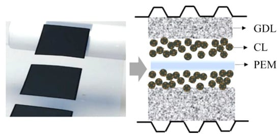
Figure 4.
Schematic diagram of the MEA structure.
A high-performance MEA should have the following characteristics.
(a) The formation of a good ion channel is a prerequisite for lowering the resistance to ion transmission [47]. Since the PEMFC adopts solid electrolytes, sulfonate is fixed on the ion exchange membrane resin rather than immersing in the electrode. Therefore, for the conduction of H+ in a solid electrolyte medium, proton channels should be introduced into CL layers of the electrode. To achieve this purpose, a three-dimensional technology must be adopted; that is, the CL layer is either soaked or sprayed with the Nafion resin for establishing an H+ conduction network in the hydrophilic network.
(b) A good electron channel is another essential factor. Although the carbon-supported platinum (Pt) CL is a good conductor of electrons, the presence of Nafion and polytetrafluoroethylene (PTFE) may affect the conductivity. Thus, considerable attention should be paid to electron conduction, in addition to accomplishing ion and gas conduction, to improve the overall MEA performance [48].
(c) To facilitate the smooth transmission of reaction gas from the GDL to CL layer for electrochemical reaction, the gas transmission resistance should be minimized. In other words, the reaction activity of CL should be maximized per unit area and mass. Therefore, the GDL must be sufficiently hydrophobic for the smooth flow of the reaction gas through the shortest channel to reach the CL. On the other hand, the generated water molecules during the reaction can be used to wet the membrane, and the excess water should be discharged to avoid gas channel blocking.
The MEA is a basic unit of electrochemical reactions in a fuel cell. In the working process, its components, such as the PEM, CL and CL support, and GDL, affect each other. Its design and preparation should follow the basic principles and characteristics of electrochemical reactions in the fuel cell, considering the final working conditions. It should be noted that the working performance of the fuel cell is influenced by the structure design and preparation technique of MEAs.
Three generations of MEA technology routes have been developed globally. The first generation is the gas diffusion electron (GDE) preparation process presented in Figure 5. In this process, the CL is directly coated on the GDL, then pressed on both sides of the PEM to obtain the MEA. The GDE process is conducive to the formation of MEA pores, which shows resistance to deformation in the PEM [52,53]. However, the CL tends to penetrate the GDL and stops functioning. Moreover, the long-term operation may cause local peeling between PEM and GDL [54,55]. Therefore, the GDE preparation process has been abandoned now.
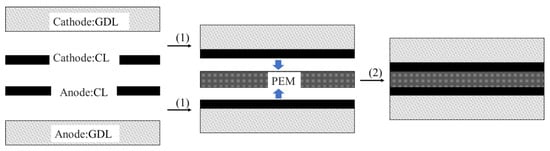
Figure 5.
Schematic diagram of the GDE preparation process.
The second generation is the catalyst coated membrane (CCM) preparation process, first proposed by Wilson et al. [56] and is currently adopted by most membrane electrode manufacturers. Specifically, the CL layer is directly coated on both sides of the PEM and then hot-pressed together with the GDL to produce the MEA, as presented in Figure 6 [57]. The CL layer of CCM bonds better with the PEM than that in the GDE process and is not prone to peeling [58]. Moreover, the interfacial impedance between the PEM and CL is small, and the CL utilization rate is high. However, due to the relatively small gas channel and water transmission resistance, the phenomenon of “water flooding” easily occurs in the MEA prepared by CCM method during the operation of the fuel cell.
Figure 6.
Schematic diagram of the CCM MEA prepared by ultrasonic spraying [51].
The proton, electron, and gas transmission channels in the CL layer are disordered, leading to a low material transmission efficiency and strong concentration polarization. Therefore, the new-generation MEA needs to realize ordered transmission of materials such as protons, electrons, reaction gas, and water for enhancing the utilization of CL. The MEA ordering can be categorized into proton conductor ordering and electronic conductor ordering, wherein the latter includes ordering of CL material and CL support material. An ordered MEA possesses good multi-phase material transmission channels for electrons, protons, water, and gas, and thus can greatly reduce the Pt load in the MEA, enhance the gas-liquid transmission inside the electrode, improve the water management capability of the electrode, and prolong the service life of the fuel cell [59,60]. On the other hand, the ordered MEA is still under investigation, with 3M being the only company known to have developed commercial ordered MEAs by preparing the CL on ordered nanostructures, as presented in Figure 7 [61].
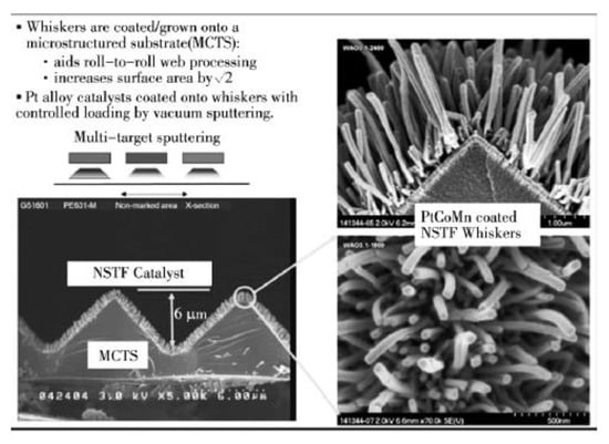
Figure 7.
Schematic diagram of ordering the MEA by 3M [61].
Mainstream MEA manufacturers outside of China include Gore, DuPont, and 3M. MEAs have also been independently developed by Barrard, Toyota, Honda, and other fuel cell and vehicle enterprises and are primarily used in their fuel cell systems. The MEA industry in China is developing slowly. However, it still needs to overcome some technical barriers. Most Chinese enterprises, such as FTXT, Tang Feng Energy, and Hydrogine Technology, were successful in building their own MEA production lines, which have preliminarily achieved commercialization and are currently in the pilot plant stage.
2.4. Proton Exchange Membrane
The PEM is a solid electrolyte membrane and a key component of fuel cells. Its main functions include isolating hydrogen and air, supporting the CL to ensure smooth reactions, and selectively conducting protons, and blocking electron transmission. It has precise control as it only allows H+ to pass through and does not use particle size as a criterion. Thus, other particulates in the fuel cell, such as ions, molecules, and ionic groups, cannot pass through it [62,63,64,65]. High-performance PEMs should have the following characteristics.
- (a)
- High proton conductivity.
- (b)
- Good chemical stability to improve the cell service life.
- (c)
- Good thermal stability, not prone to degradation at high temperatures.
- (d)
- Good mechanical performance to ensure negligible or no morphological changes when switching between dry and wet states during operation of the fuel cell.
- (e)
- High utilization rate of raw materials, low gas permeability, and low point permeability coefficient of water.
- (f)
- Low price.
- (g)
- Good formability.
The investigations into PEM mainly focused on the three types of membranes: perfluorinated PEMs, partially fluorinated polymer PEMs, and non-fluorinated polymer PEMs. Currently, perfluorosulfonic acid (PFSA) PEM is most widely used. In the 1960s, US DuPont developed PFSA ion exchange membranes (later known as the Nafion series) [66]. Figure 8 displays the structural formula of the Nafion resin. It has a fluorocarbon main chain, with the branched chain composed of ether with sulfonic acid groups, demonstrating high chemical stability. The sulfonic acid end group (-SO3H) is hydrophilic and facilitates the aggregation of hydrophilic phases to form an ion cluster network when the membrane is wet and conducts protons. The PFSA ion exchange membrane exhibits advantages such as stable mechanical strength, high chemical stability, high conductivity under humid environments, and high current density at low temperatures, all of which are conducive to proton conduction. However, it has the following three defects. (1) The requirements for the monomer synthesis process are stringent, resulting in a high material cost and also a higher price of finished products. (2) Both the preparation processes of the PFSA membrane and its waste disposal cause environmental pollution.
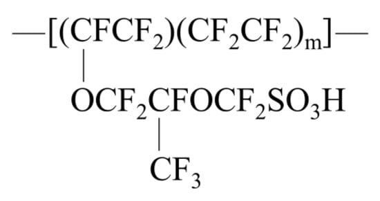
Figure 8.
Structural formula of the Nafion resin.
To reduce the price of PEMs and facilitate the synthesis of perfluoropolymers, the research has shifted focus onto partially fluorinated polymer PEMs and non-fluorinated polymer PEMs [67,68]. The partially fluorinated polymer PEM replaces PFSA resin with partially substituted fluoride or blends the inorganic or other non-fluorides with the fluoride. Ballard of Canada developed the BAM-series PEM, a typical partially fluorinated polystyrene PEM, to improve the performance of the sulfonated polystyrene PEM. Its thermal stability, chemical stability, and moisture content have been considerably enhanced, which exceeded the performance of the Nafion117 and Dow membranes. At the same time, it is less expensive than perfluorinated membranes and can replace perfluorinated sulfonic acid membranes only in some cases. However, the application of these polystyrene PEM is limited due to their small molecular weight and insufficient mechanical strength.
To fundamentally address the high cost and exhaust pollution of perfluorinated sulfonic acid membranes, a new class of PEMs called non-fluoropolymer PEMs has been developed. The fully aromatic polymer, as a special macromolecule, shows excellent properties such as high mechanical strength, good chemical, and electrochemical stability, strong heat resistance, and low price. A novel non-fluoropolymer PEM, as the most promising alternative to the Nafion membrane, has been prepared by introducing strong acid ion groups into the aromatic ring. Specifically, polyarylether polymers (PPS/PES/PEK/PKS), polyimide (PI), and polybenzimidazole (PBI) have been extensively studied because of their excellent chemical stability, high-temperature resistance, environmental friendliness, and low cost [69,70]. However, for PPS/PES/PEK/PKS membranes, it is only under the condition of high swelling that they can have the equivalent proton conductivity as the Nafion membrane, and the fuel cell working condition does not permit excessively high swelling rates. For PI membranes, phosphoric acid is not covalently linked to the PBI chain, and phosphoric acid is water-soluble. As a result, as the fuel cell reaction produces water, phosphoric acid will also be lost, leading to the degradation of the performance of the fuel cells.
Enterprises involved in the R&D of PFSA PEMs mainly include DuPont, Gore, 3M, Mitsubishi, AGC, and Solvay. Among these, currently, the most widely used PEM in the market is DuPont’s Nafion membrane. The Nafion membrane has higher chemical stability, higher mechanical strength, and higher conductivity in humid working environments than other PEMs. Almost all commercial PFSA PEMs are based on the Nafion structure. However, the membrane material demands high temperature and moisture content, while proton conductivity deteriorates considerably at medium and high temperatures. In addition, the preparation becomes difficult when used in direct methanol fuel cells, since the permeability of methanol is high. It can be mentioned that the progress of China’s PEM technology has been slow. At this stage, few enterprises (e.g., Shandong Dongyue future hydrogen energy materials) produce large-scale MEAs. The thickness of PEMs produced by Dongyue has reduced from 50 µm to 15 µm [71]. Table 3 lists the representative manufacturing enterprises in China and other countries and their PEM products.
Table 3.
PEM manufacturers and their products.
2.5. Catalyst Layer
The CL, being the most important component of the MEA, must ensure the continuous transmission of electrons, protons, and reaction gases and timely discharge of reaction product water. Generally, three components participate in chemical reactions in the fuel cell, namely gas (hydrogen and oxygen), electrons, and protons, all of which require rapid and stable transfer. Gas is transferred through voids, electrons are transferred through conductive carriers, and protons are transferred through PEMs, and hence the CL material should satisfy the high requirements for ensuring better efficiency of the fuel cell. Firstly, it must be porous to allow hydrogen and oxygen to pass through. Secondly, since sufficient current can be achieved only with good conductivity, the CL must be in close contact with the PEM to ensure the smooth transfer of protons. Thirdly, the CL must be sufficiently thin to minimize the cell potential loss due to proton migration and penetration of reaction gas into deep parts of the layer. Finally, the by-product water generated by the reaction must be effectively discharged to avoid immersion of the CL in water, which causes inaccessibility of the gas.
Currently, PEMFC CLs are Pt-based and thus are expensive and limited. According to the DOE US fuel cell cost analysis report of 2017 [71], the CL cost accounted for 41% of the overall cell stack cost. Thus, the high CL cost severely restricts the mass production and application of the PEMFC. In addition, the technical concerns such as activity, stability, and large-scale preparation of CLs have become the bottlenecks restricting the development of fuel cells. However, the investigations and demonstrative works on CLs have been adopted by many countries. Table 4 displays the power, Pt consumption, and durability of fuel cell vehicles developed by several representative automobile companies. It could be observed that Toyota demonstrated the least Pt used (approximately 0.17 g/kW), which was still far from the target of 0.125 g/kW of the US DOE [72].
Table 4.
Power, Pt consumption, and durability of various fuel cell vehicle enterprises [73].
Pt is a classic CL in the field of electrocatalysis because of its high activity, attracting much attention and extensive research. However, its scarcity and high price limit its application. The annual demand for Pt in the automotive industry, if all cars are driven by fuel cells, would be as high as over 1000 tons, which is approximately five years’ global Pt output (200 t annually) [74,75]. Therefore, pursual for low-Pt or non-Pt CLs for fuel cells has gained attention. The cost and stability problems of commercial CLs can be solved by the following approaches.
(a) Manipulation of Pt structure. For instance, the utilization rate of Pt atoms can be improved by synthesizing CLs with a specific morphology [76,77], and the activity can be enhanced by controlling the exposed crystal plane ratio during crystal growth [78].
(b) Alloying of Pt to reduce Pt consumption [79,80,81,82,83]. For example, the CL stability and toxic tolerance can be effectively improved by alloying Pt with transition metals (e.g., Ti, Cr, V, Mn, Fe, Co, Ni, and Cu) on carbon supports.
(c) Development of novel, highly active carrier materials to improve the stability and overall properties of Pt [84,85,86]. In general, the oxygen reduction reaction (ORR) activity and stability of the CL can be enhanced by some specific interactions between the Pt CL and the carrier. In addition, the carrier should have a high specific surface area, strong physical, electrochemical, and thermal stability, and good conductivity to facilitate Pt recovery.
(d) Development of non-Pt CLs with low cost, high catalytic activity, and excellent stability [87,88,89,90,91], such as transition metal–nitrogen–carbon (M-N-C) CLs, transition metal oxides, chalcogenides, nitrides, and oxynitrides.
The comparison of the advantages and disadvantages of various low-Pt or non-Pt CLs is presented in Table 5. The main aim of the PEMFC CL research is to replace Pt and other precious metals to reduce the cost. However, commercial Pt/C CLs are superior to non-Pt-based CLs in terms of stability, current density, and ORR catalytic activity in acidic solutions.
Table 5.
Comparison of fuel cell CLs.
China’s CL industry has shown slow progress, still depending on the raw materials imported from TANAKA, Johnson Matthey, and UMICORE. Although several Chinese enterprises and institutes have investigated fuel cell CLs with some achievements, it is difficult for their products to meet the technical specifications of commercial needs. Fuel cell CLs, in contrast to ordinary CLs, require better performance in activity, stability, and durability. Further, commercial products can only be manufactured on a large scale by repetitive testing, optimizing, and application.
2.6. Gas Diffusion Layer
The GDL is a wet-proof carbon-based material used on both sides of the fuel cell anode and cathode between the flow field plate and the CL layer. The GDL plays an important role in homogenizing gas distribution, controlling MEA moisture, conducting electricity and heat, and supporting the electrode structure. The GDL is deliberately designed to be porous in order to perform these functions. The pore zone primarily regulates the transmission of reactants and by-product water flowing in the opposite direction, while the remaining solid structure provides channels for electron and heat transmission. The GDL is typically composed of the microporous layer (MPL) and the gas diffusion backing (GDB) layer [92,93], as depicted in Figure 9.
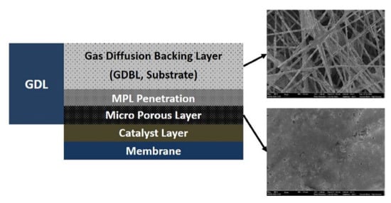
Figure 9.
Schematic diagram of the GDL structure [92].
The MPL, though an independent layer, has no clear interface with the GDL. The MPL consists of small-scale carbon powder/hydrophobic aggregates that can be several times smaller than the GDL opening. These aggregates have the ability to penetrate relatively large pores and modify their structures. The main functions of the MPL are to improve the pore structure of the substrate, reduce the contact resistance between the substrate and CL layer, achieve a rapid and homogenous distribution of reaction gas through the diffusion layer to the CL layer surface for reactions, and drain the generated water in time to prevent flooding of the CL layer. The gas diffusion channel of the MPL is composed of treated hydrophobic pores containing PTFE as a common water repellent. Therefore, these hydrophilic pores without the hydrophobic treatment can act as transfer channels for product water.
The GDB layer mainly functions to diffuse gas, support the MPL, and stabilize the MEA structure [94,95]. An ideal GDB material should possess high mechanical strength, high thermal and chemical resistance, and high stability and durability, in addition to meeting the requirements of mass transmission, heat conduction, and conductivity. The transmission characteristics of the GDB layer largely depend on its engineering parameters, and the development of a GDB layer with the best transmission performance has gained considerable attention in recent years [93,96,97]. With advancing R&D, GDB performance has improved; however in-depth understanding of the causes and directions for improvement is still lacking. A wide range of porous materials has been considered as potential GDB materials, which are often classified into two categories. Carbon-based GDB includes carbon paper, carbon cloth, carbon foam, and carbon felt, while metal-based GDB materials include metal mesh, metal foam, and micro-processed metal [98].
The properties of carbon-based GDB, such as high permeability, high chemical stability, high electronic conductivity, high elasticity, and controllable pore structure, facilitate their application PEMFC. Among all, carbon paper is the most common carbon-based GDB. It is composed of arbitrarily stacked ultra-fine carbon fibers that have been treated with a hydrophobic agent. Carbon paper with hydrophobic treatment has an optimal microstructure and can realize effective mass transfer. In contrast, the metal-based GDB inherently exhibits high electrical and thermal conductivity, high mechanical strength, and good weldability and plasticity. Moreover, the processed metal-based GDB can achieve a high specific surface area, controllable pores, and satisfactory permeability and wettability. The foam metal GDL is an integrated design of BPP and GDL, eliminating the contact impedance between BPP and GDL, thus improving the material and heat distribution uniformity. Therefore, the foam metal is a potential direction of GDB research [99], though it is still in the early stage of development and requires further evidence to prove its feasibility.
Outside China, the carbon paper industry is almost monopolized by companies, such as Toray of Japan, SGL of Germany, and Ballard of Canada, that are highly competitive. All of their products are primarily based on carbon fibers produced by Japan. Among all, Toray’s products possess stable performance and also a substantial market share.
Most of the Chinese manufacturers are in the small-scale production stage, while General Hydrogen is delivering sample products to customers for testing. The gap between China and other countries can be attributed to the insufficient developments in Chinese enterprises. Therefore, the technical and material basis for mass production is still a constraint, posing difficulties in the vehicle testing of the trial products. Furthermore, Chinese carbon fiber precursors tend to have a large diameter, excessive deviation, low strength, and small crystal orientation, with more defects and holes. All of these limit the performance of the carbon fiber precursor in China and lead to the import of the carbon fibers from other countries. Though the problem of raw material supply is solved through imports, technical barriers remain in manufacturing carbon paper from carbon fiber. Besides, the lack of the key apparatus required in mass production in China is another constraint.
2.7. Air Compressor
The air compressor is the most important auxiliary component in the fuel cell system. It functions to compress the air required by the fuel cell vehicle to meet the stack working requirements and transmit the compressed air to the stack for electrochemical reactions. This may result in enhancing the power density and efficiency of the fuel cell [100,101,102]. The compressor consumes 10–20% of the output power of the fuel cell stack, which is the highest among the auxiliary components while providing the stack with high-pressure air [103,104]. The air compressor is the other most expensive component in the fuel cell power system, excluding the stack [105,106]. Importantly, the gas supply pressure at the cathode inlet of the stack can be increased by the compressor to reduce Pt consumption [107,108] and thus the overall cost of the fuel cell system. Compressors for fuel cell systems should have the following characteristics.
(a) Being oil-free. The air compressor should supply high-pressure compressed gas to the stack without any impurities and chemicals (less than 100 ppm [109]) to avoid poisoning of the PEM fuel cell during electrochemical reactions.
(b) Miniaturization and lightweight design. In the industrialization of fuel cell vehicles, power density and cost are two bottlenecks. Therefore, to enhance power density and reduce cost, the fuel cell power system should follow stringent requirements for the volume and weight of the compressor [110].
(c) Wide flow coverage. The turndown ratio of the compressor for fuel cells should be 20, as per DOE requirements [110].
(d) Good noise, vibration, and harshness (NVH) characteristics. The NVH of the compressor assembly is the largest contributor to the NVH of the fuel cell power system and thus should be optimized [111].
(e) Fast dynamic response. The compressor must respond in a timely fashion to control the airflow and pressure.
(f) High material requirements. The key compressor components should possess low-cost, wear-resistant coatings and stable friction performance to build inexpensive, low-noise, and durable compressors.
Compressors can be categorized into positive displacement compressors and aerodynamic compressors based on their working principle. Positive displacement compressors introduce gas into a closed compartment and increase the internal pressure by compressing the volume occupied by the gas, transforming mechanical energy into pressure energy. Based on the compression method, positive displacement compressors can be further divided into reciprocal, rotary, scroll, spiral, and roots types. Aerodynamic compressors, on the other hand, utilize the high-speed rotation of the impeller to force high-speed gas flow, generating kinetic energy. When passing through the diffuser ring, the increase in cross-section area reduces the airflow rate, converting the kinetic energy into pressure energy and thus increasing the pressure. Aerodynamic compressors include centrifugal and axial-flow types. Theoretically, all the compressors mentioned above have the potential to be used in fuel cell power systems.
The compressors for fuel cells on the market mainly include screw, roots, and centrifugal types, among which the centrifugal compressors can be further divided into geared and high-speed direct-drive types, as depicted in Figure 10. The most widely used compressor on the market is the double screw type that mainly operates through rotor rotation. The air is sucked in as the tooth space becomes larger, then pressed to the exhaust end by the meshing of male and female rotors, finally discharging pressurized air. The screw-type compressors possess high reliability, simple structure, and high efficiency and can be ideal for fuel cell application. However, the shortcomings such as high noise, large weight and volume, and short service life have resulted in their gradual replacement by other compressors for vehicle use. On the other hand, the centrifugal compressor is usually driven by a direct motor. Under ultrahigh-speed rotation of the motor rotor, the impeller pushes the gas to rotate at high speed, which interacts with the volute to produce the high-pressure and large-flow air, converting mechanical energy into kinetic energy of the air. The centrifugal-type is considered as one of the most promising air compression methods because of its compact structure, small size, good sealing, lightweight, low vibration, and high efficiency under provided working conditions.
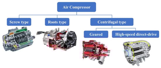
Figure 10.
Classification of compressors for fuel cell vehicles.
The air compressor is a critical research area in the compressor and automobile industries since it is a key component of the fuel cell vehicle. UQM, Garrett, Liebherr, FISCHER, Aeristech, and Toyota Industries are popular compressor enterprises outside China, while Xeca Turbo, ZCJSD, Easyland, and Snowman Group are well-known companies in China. Table 6 compares the product performance of the major compressor enterprises. The pressure ratios of the compressors are within the range of 1.8–4.0, the flow range is 68–150 g∙s−1, and the power is within 14–25 kW. China shows remarkable progress in compressor manufacturing, and presently the Chinese compressors can effectively replace the imported ones.
Table 6.
Performance comparison of products manufactured by major compressor enterprises.
2.8. Hydrogen Circulation System
The hydrogen supply system is a core subsystem of the fuel cell engine [114,115]. The recycling of hydrogen not only improves hydrogen utilization and economy but also optimizes water management by the uniform distribution of water in the anodic compartment. Water management becomes crucial since too high or too low water content of the anode can affect the performance and service life of the fuel cell. Specifically, if the water content is too low, the PEM will be excessively dry, affecting the proton transmission. On the other hand, higher content of water in the anode causes flooding and local hydrogen deprivation [116,117]. The schemes of the hydrogen circulation system mainly include the single ejector, double ejector, single hydrogen circulation pump, and ejector and circulation pump in parallel, as presented in Figure 11.
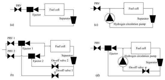
Figure 11.
Schemes of the hydrogen circulation system: (a) single ejector; (b) double ejector; (c) hydrogen circulation pump; (d) ejector and circulation pump in parallel.
The single ejector mode is presented in Figure 11a. In this mode, the discharged hydrogen from the storage tank is depressurized through the pressure regulating valve (PRV). The excess hydrogen remaining after stack reactions is used as a secondary flow, which enters the stack again after passing through the ejector. The ejector is a supercharging device typically containing a suction chamber, a mixing chamber, and a diffusor [117,118]. The components and working principle of the ejector are presented in Figure 12. The fluids entering the ejector can be divided into high-pressure working fluids and low-pressure ejection fluids based on the fluid pressure. The working fluid flows out of the nozzle at high speed and enters the isobaric mixing chamber. A huge pressure difference is created due to the formation of a low-pressure area at the nozzle outlet and entrains the ejection fluid into the ejector. The working fluid and ejection fluid mix uniformly, and exchange energy in the isobaric and isovolumetric mixing chambers and are finally discharged from the diffusor [119,120,121,122,123]. The ejector has the advantages of compact structure, reliable operation, no moving parts, no pollution, and no parasitic power, etc., and thus are ideal for use in the anode exhaust cycling device of the hydrogen–oxygen fuel cell vehicle. However, the ejection effect is not ideal at low powers because the primary flow has low pressure. Hyundai Motor Company has adopted this single ejector mode in its Nexo fuel cell passenger cars.
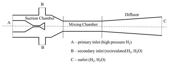
Figure 12.
Schematic diagram of an ejector.
The US DTI proposed the double ejector scheme in 2010 [124] since a single ejector is incapable of covering all the operating points. In this scheme, the hydrogen circulation system is composed of a hydrogen diverter valve and two ejectors with different flow rates. The high-flow ejector is used for hydrogen circulation at high-power range operating conditions of the stack, while the low-flow ejector is used at low-power range conditions. The hydrogen recovery mode using double-ejector mode has a larger working range to meet the needs of the stack under various powers than that by a single ejector. Nevertheless, the included ejector increases the system volume, mass, and cost, increasing the complexity of the system structure and control strategy.
The hydrogen recovery mode of a single hydrogen circulating pump is presented in Figure 11c, which is characterized by a rapid response, wide working range, and effective adjustment according to the working conditions of the fuel cell. A typical application example can be Toyota Motor Company, which applied two-lobe roots-type hydrogen circulation pumps on Mirai fuel cell passenger cars. Unlike conventional gas circulators, it is difficult for the hydrogen circulating pump to have good sealing, strong water resistance, large flow, stable pressure output, and oil-free features. Importantly, the most challenging issue is that the hydrogen circulating pump tends to freeze at low temperatures, making it impossible for the system to start. In addition, the high R&D cost and the high price of the hydrogen pump also restrict its market development.
The parallel mode of the hydrogen circulation pump and ejector is presented in Figure 11d, which was adopted by the anode hydrogen supply scheme of the fuel cell system in ARGONNE Laboratory [125]. The hydrogen circulation pump is used for active hydrogen circulation in the low-power and small-flow stages, whereas the ejector is used for passive hydrogen circulation at high power and large flows, thus showing two-mode functioning. This scheme reduces energy waste when the hydrogen circulation pump operates in the high-power range of the stack while solving the problem of poor ejection effect in the low power range simultaneously. However, the parallel scheme increases the complexity, control difficulty, and cost of the system.
The hydrogen circulation system technology of China has made rapid progress, gradually replacing imported hydrogen circulation systems with domestic systems. Hydrogen cycle suppliers in China mainly include Wise Drive and Dongdeshiye. Dongdeshiye has reported small batch applications of domestic hydrogen circulating pumps, achieving a cold start temperature of −40 °C. The ejectors developed by FTXT have been running stably on the fuel cell engine independently developed by the company for half a year.
3. Problems and Suggestions of Industry Development in China
The fuel cell industry in China is still in its early stages of development. China needs to address some problems and challenges such as weak industrial innovation capability and low equipment level.
(1) The vehicle enterprises lack a stable parts supply system due to a weak supply chain system. Further, the insufficient engineering capacity results in low process quality of parts such as insufficient product consistency, reliability, and durability, thus failing to meet vehicle requirements.
(2) Although key technologies in power density, Pt load, and MEA durability have been deployed, there is still huge scope remaining. A significant gap in performance and cost exists between MEAs and BPP manufactured in China and other countries.
China has proposed the development vision of achieving peak carbon dioxide emissions by 2030 and carbon neutrality by 2060. The energy revolution to achieve the carbon goals can be brought about by actively developing the hydrogen energy industry and promoting fuel cell vehicles. Further, to accelerate the development of the hydrogen energy and fuel cell vehicle industry, we should expedite technical breakthroughs.
(1) Governments should focus on new growth possibilities of hydrogen energy development, plan the national roadmap for hydrogen energy and fuel cell development, and promote the balanced development of the hydrogen energy industry.
(2) Industries should focus on handling key material technologies for hydrogen energy, improve the main performance indicators continuously, such as the MEA power density, stack power density, and service life, keep enhancing the reliability, stability, and durability of fuel cells, support the technological development and innovation of new fuel cells, develop low-Pt and non-Pt CLs, high-performance PEMs, carbon papers, and GDLs with independent intellectual property rights, and improve the mass production capacity of MEAs and BPP.
4. Conclusions
China has made significant breakthroughs in fuel cell technologies, providing important possibilities for realizing zero-emission energy utilization. China needs to firmly grasp the trends and opportunities of global energy reform and development to accelerate the development of the fuel cell industry and transform towards clean and low-carbon energy. The fuel cell vehicle industry in China has preliminarily mastered core technologies, including the fuel cell stack, BPP, MEA, PEM, CL, carbon paper, compressor, and hydrogen circulation system. The independent R&D capability of fuel cell stacks has been gradually strengthened, and the rated power and bulk power density of fuel cell stacks have both been considerably improved. High localization rates of MEA and BPP have been achieved with relatively mature production processes; however, Pt loading and power need to be optimized. The market of PEM, CL, carbon paper, and other key materials, on the other hand, is still dominated by imported products. The performance of core components such as the compressor and the hydrogen circulation system can match the international standard, but durability and stability are yet to be verified. In summary, fuel cell vehicles in China seriously face some challenges at the early stage of industrial development, such as the lagging basic system, imperfect standards and regulations, weak industrial innovation capability, high product costs, and uncertain technical safety and stability levels. Further, China should accelerate the technical breakthroughs, transformations, and applications of key materials and core components.
Author Contributions
Conceptualization, Y.Z. and Z.Y.; methodology, Y.Z. and J.W.; investigation, Y.Z.; resources, J.W.; data curation, Y.Z.; writing—original draft preparation, Y.Z.; writing—review and editing, Y.Z.; visualization, Y.Z.; supervision, Z.Y.; project administration, J.W.; funding acquisition, Y.Z. All authors have read and agreed to the published version of the manuscript.
Funding
This research was funded by the Science and Technology Research Program of Chongqing Municipal Education Commission, grant number KJQN202201121 and Scientific Research Foundation of Chongqing University of Technology.
Acknowledgments
This work was supported by Guide project of CATARC (Grant number 21233419), which is gratefully acknowledged.
Conflicts of Interest
The authors declare that they have no known competing financial interests or personal relationships that could have appeared to influence the work reported in this paper.
Correction Statement
This article has been republished with a minor correction to the Reference part. This change does not affect the scientific content of the article.
Abbreviations
The following abbreviations are used in this manuscript:
| Al | aluminum |
| BPP | bipolar plate |
| CCM | catalyst coated membrane |
| CL | catalyst layer |
| Cu | copper |
| DOE | the US Department of Energy |
| FCHEA | the US Fuel Cell and Hydrogen Energy Association |
| FCH-JU | the Fuel Cells and Hydrogen Joint Undertaking |
| ICR | interfacial contact resistance |
| GDB | gas diffusion backing |
| GDE | gas diffusion electron |
| GDL | gas diffusion layer |
| MEA | membrane electrode assembly |
| METI | the Ministry of Economy, Trade, and Industry |
| M-N-C | metal–nitrogen–carbon |
| MPL | microporous layer |
| Ni | nickel |
| ORR | oxygen reduction reaction |
| PBI | polybenzimidazole |
| PEM | proton exchange membrane |
| PI | polyimide |
| PPS/PES/PEK/PKS | polyarylether polymers |
| PFSA | perfluorosulfonic acid |
| PRV | pressure regulating valve |
| Pt | platinum |
| PTFE | polytetrafluoroethylene |
| R&D | research and development |
| SS | stainless steel |
| Ti | titanium |
References
- Zhu, L.; Hu, L.; Yüksel, S.; Dinçer, H.; Karakuş, H.; Ubay, G.G. Analysis of Strategic Directions in Sustainable Hydrogen Investment Decisions. Sustainability 2020, 12, 4581. [Google Scholar] [CrossRef]
- Sun, C.; Zhang, H. Review of the Development of First-Generation Redox Flow Batteries: Iron-Chromium System. ChemSusChem 2021, 15. [Google Scholar] [CrossRef] [PubMed]
- The Strategic Road Map for Hydrogen and Fuel Cells; Hydrogen and Fuel Cell Strategy Council: Danbury, CT, USA, 2019.
- Hydrogen Roadmap Europe: A Sustainable Pathway for the European Energy Transition; Fuel Cells and Hydrogen Joint Undertaking: Danbury, CT, USA, 2019.
- Wang, Y.; Chen, K.S.; Mishler, J.; Cho, S.C.; Adroher, X.C. A review of polymer electrolyte membrane fuel cells: Technology, applications, and needs on fundamental research. Appl. Energy 2011, 88, 981–1007. [Google Scholar] [CrossRef]
- Gröger, O.; Hubert, A. Gasteiger and Jens-Peter Suchsland. Review-Electromobility: Batteries or Fuel Cells? J. Electrochem. Soc. 2015, 162, A2605–A2622. [Google Scholar]
- Wang, F.; Harindintwali, J.D.; Yuan, Z.; Wang, M.; Li, S.; Yin, Z.; Huang, L.; Fu, Y.; Li, L.; Chang, S.X.; et al. Technologies and perspectives for achieving carbon neutrality. Resour. Conserv. Recycl. 2022, 2, 176. [Google Scholar] [CrossRef] [PubMed]
- Pollet, B.G.; Staffell, I.; Shang, J.L. Current status of hybrid, battery and fuel cell electric vehicles: From electrochemistry to market prospects. Electrochim. Acta 2012, 84, 235–249. [Google Scholar] [CrossRef]
- Whiston, M.M.; Lima Azevedo, I.M.; Litster, S.; Samaras, C.; Whitefoot, K.S.; Whitacre, J.F. Hydrogen Storage for Fuel Cell Electric Vehicles: Expert Elicitation and a Levelized Cost of Driving Model. Environ. Sci. Technol. 2020, 55, 553–562. [Google Scholar] [CrossRef]
- Baba, M.A.; Labbadi, M.; Cherkaoui, M.; Maaroufi, M. Fuel cell electric vehicles: A review of current power electronic converters Topologies and technical challenges. IOP Conf. Ser. Earth Environ. Sci. 2021, 785, 012011. [Google Scholar] [CrossRef]
- Available online: https://www.miit.gov.cn/xwdt/szyw/art/2020/art_4390362916324365a260ed97d7558f18.html (accessed on 4 January 2023).
- Available online: http://jjs.mof.gov.cn/zhengcefagui/202009/t20200918_3591168.htm (accessed on 4 January 2023).
- Lf, A.; Zt, A.; Shc, B. Recent development of hydrogen and fuel cell technologies: A review. Energy Rep. 2021, 7, 8421–8446. [Google Scholar]
- Qiu, D.; Peng, L.; Yi, P.; Lehnert, W.; Lai, X. Review on proton exchange membrane fuel cell stack assembly: Quality evaluation, assembly method, contact behavior and process design. Renew. Sustain. Energy Rev. 2021, 152, 111660. [Google Scholar] [CrossRef]
- Qiu, Y.; Zeng, T.; Zhang, C.; Wang, G.; Wang, Y.; Hu, Z.; Meng, Y.; Wei, Z. Progress and challenges in multi-stack fuel cell system for high power applications:architecture and energy management. Green Energy Intell. Transp. 2023, 100068. [Google Scholar] [CrossRef]
- Available online: https://www.shpt.com/pc/productDetail.html?p=29 (accessed on 4 January 2023).
- Available online: https://baijiahao.baidu.com/s?id=1746112652127783625&wfr=spider&for=pc (accessed on 4 January 2023).
- Available online: http://www.sl-power.com/FCStack/index_154.aspx (accessed on 4 January 2023).
- Available online: https://www.sinosynergypower.com/product/40.html (accessed on 4 January 2023).
- Available online: https://www.h-rise.com/Products_208.html (accessed on 4 January 2023).
- Silva, R.; Franchi, D.; Leone, A.; Pilloni, L.; Masci, A.; Pozio, A. Surface conductivity and stability of metallic bipolar plate materials for polymer electrolyte fuel cells. Electrochim. Acta 2006, 51, 3592–3598. [Google Scholar] [CrossRef]
- Taherian, R.; Nasr, M. Performance and material selection of nanocomposite bipolar plate in proton exchange membrane fuel cells. Int. J. Energy Res. 2014, 38, 94–105. [Google Scholar] [CrossRef]
- Peker, M.F.; Cora, Ö.N.; Koç, M. Investigations on the variation of corrosion and contact resistance characteristics of metallic bipolar plates manufactured under long-run conditions. Int. J. Hydrogen Energy 2011, 36, 15427–15436. [Google Scholar]
- Li, X.; Sabir, I. Review of bipolar plates in PEM fuel cells: Flow-field designs. Int. J. Hydrogen Energy 2005, 30, 359–371. [Google Scholar] [CrossRef]
- Antunes, R.A.; Oliveira, M.C.L.; Ett, G.; Ett, V. Corrosion of metal bipolar plates for PEM fuel cells: A review. Int. J. Hydrogen Energy 2010, 35, 3632–3647. [Google Scholar] [CrossRef]
- US Department of Energy. Fuel Cell Technical Ream Roadmap; US Department of Energy: Washington, DC, USA, 2013.
- Hermann, A.; Chaudhuri, T.; Spagnol, P. Bipolar plates for PEM fuel cells: A review. Int. J. Hydrogen Energy 2005, 30, 1297–1302. [Google Scholar] [CrossRef]
- Guo, N.; Leu, M. Effect of different graphite materials on the electrical conductivity and flexural strength of bipolar plates fabricated using selective laser sintering. Int. J. Hydrogen Energy 2012, 37, 3558–3566. [Google Scholar] [CrossRef]
- Mathur, R.; Dhakate, S.; Gupta, D.; Dhami, T.; Aggarwal, R. Effect of different carbon fillers on the properties of graphite composite bipolar plate. J. Mater. Process. Technol. 2008, 203, 184–192. [Google Scholar] [CrossRef]
- Ji, S.; Hwang, Y.-S.; Park, T.; Lee, Y.H.; Paek, J.Y.; Chang, I.; Lee, M.H.; Cha, S.W. Graphite foil based assembled bipolar plates for polymer electrolyte fuel cells. Int. J. Precis. Eng. Manuf. 2012, 13, 2183–2186. [Google Scholar] [CrossRef]
- Wilson, M.; Busick, D. Composite Bipolar Plate for Electrochemical Cells. U.S. Patent US6248467B1, 19 June 2001. [Google Scholar]
- Bisaria, M.K.; Andrin, P.; Abdou, M.; Cai, Y. Injection Moldable Conductive Aromatic Thermoplastic Liquid Crystalline Polymeric Compositions. U.S. Patent US6379795, 30 April 2002. [Google Scholar]
- Wu, S.; Yang, W.; Yan, H.; Zuo, X.; Cao, Z.; Li, H.; Shi, M.; Chen, H. A review of modified metal bipolar plates for proton exchange membrane fuel cells. International. J. Hydrogen Energy 2021, 46, 8672–8701. [Google Scholar] [CrossRef]
- Karimi, S.; Fraser, N.; Roberts, B.; Foulkes, F.R. A Review of Metallic Bipolar Plates for Proton Exchange Membrane Fuel Cells: Materials and Fabrication Methods. Adv. Mater. Sci. Eng. 2012, 2012, 1–22. [Google Scholar] [CrossRef]
- Chen, B.; Ke, W.; Luo, M.; Wang, J.; Tu, Z.; Pan, M.; Zhang, H.; Liu, X.; Liu, W. Operation characteristics and carbon corrosion of PEMFC (Proton exchange membrane fuel cell) with dead-ended anode for high hydrogen utilization. Energy 2015, 91, 799–806. [Google Scholar] [CrossRef]
- Jin, J.; Hu, M.; Zhao, X. Investigation of incorporating oxygen into TiN coating to resist high potential effects on PEMFC bipolar plates in vehicle applications. Int. J. Hydrogen Energy 2020, 45, 23310–23326. [Google Scholar] [CrossRef]
- Mani, S.; Srinivasan, A.; Rajendran, N. Effect of nitrides on the corrosion behaviour of 316L SS bipolar plates for Proton Exchange Membrane Fuel Cell (PEMFC). Int. J. Hydrogen Energy 2015, 40, 3359–3369. [Google Scholar] [CrossRef]
- Chen, B.; Wang, J.; Yang, T.; Cai, Y.; Pan, M.; Tu, Z.; Zhang, C.; Chan, S.H.; Yu, Y. Mitigation studies of carbon corrosion by optimizing the opening size of the cathode outlet in a proton exchange membrane fuel cell with dead-ended anode. Energy Convers. Manag. 2016, 119, 60–66. [Google Scholar] [CrossRef]
- Wang, Y.; Zhang, S.; Lu, Z.; Wang, L.; Li, W. Preparation and performances of electrically conductive Nb-doped TiO2 coatings for 316 stainless steel bipolar plates of proton exchange membrane fuel cells. Corros. Sci. 2018, 142, 249.e57. [Google Scholar] [CrossRef]
- Barranco, J.; Barreras, F.; Lozano, A.; Maza, M. Influence of CrN-coating thickness on the corrosion resistance behaviour of aluminium-based bipolar plates. J. Power Sources 2011, 196, 4283.e9. [Google Scholar] [CrossRef]
- Cheng, X.; Shi, Z.; Glass, N.; Zhang, L.; Zhang, J.; Song, D.; Liu, Z.-S.; Wang, H.; Shen, J. A review of PEM hydrogen fuel cell contamination: Impacts, mechanisms, and mitigation. J. Power Sources 2007, 165, 739.e56. [Google Scholar] [CrossRef]
- Yun, Y.H. Deposition of gold-titanium and gold-nickel coatings on electropolished 316L stainless steel bipolar plates for proton exchange membrane fuel cells. Int. J. Hydrogen Energy 2010, 35, 1713–1718. [Google Scholar] [CrossRef]
- Bagherzadeh, M.; Jaberinia, F. Electrochemical study of Monel alloy corrosion in hydrochloric acid solution and pyrrolidine dithiocarboxylate self-assembled monolayers as its corrosion protector. J. Alloys Compd. 2018, 750, 677–686. [Google Scholar] [CrossRef]
- Yao, K.; Adams, D.; Hao, A.; Zheng, J.P.; Liang, Z.; Nguyen, N. Highly Conductive and Strong Graphite-Phenolic Resin Composite for Bipolar Plate Applications. Energy Fuels 2017, 31, 14320–14331. [Google Scholar] [CrossRef]
- Li, W.; Jing, S.; Wang, S.; Wang, C.; Xie, X. Experimental investigation of expanded graphite/phenolic resin composite bipolar plate – ScienceDirect. Int. J. Hydrogen Energy 2016, 41, 16240–16246. [Google Scholar] [CrossRef]
- Him, J.; Lee, D. Development of composite-metal hybrid bipolar plates for PEM fuel cells. Int. J. Hydrogen Energy 2012, 37, 12504–12512. [Google Scholar]
- Lin, S.Y.; Chang, M. Effect of microporous layer composed of carbon nanotube and acetylene black on polymer electrolyte membrane fuel cell performance. Int. J. Hydrogen Energy 2015, 40, 7879–7885. [Google Scholar] [CrossRef]
- Litster, S.; Mclean, G. PEM fuel cell electrodes. J. Power Sources 2004, 130, 61–76. [Google Scholar] [CrossRef]
- Fu, X.; Gao, R.; Jiang, G.; Li, M.; Li, S.; Luo, D.; Hu, Y.; Yuan, Q.; Huang, W.; Zhu, N.; et al. Evolution of atomic-scale dispersion of FeNx in hierarchically porous 3D air electrode to boost the interfacial electrocatalysis of oxygen reduction in PEMFC. Nano Energy 2021, 83, 105734. [Google Scholar] [CrossRef]
- Zhang, H.; Shen, P.K. Advances in the high performance polymer electrolyte membranes for fuel cells. Chem. Soc. Rev. 2012, 41, 2382–2394. [Google Scholar] [CrossRef]
- Li, Y.; Zhou, Z.; Liu, X.; Wu, W.-T. Modeling of PEM fuel cell with thin MEA under low humidity operating condition. Appl. Energy 2019, 242 Pt 1285-176, 1513–1527. [Google Scholar] [CrossRef]
- Ticianelli, E.A. Methods to Advance Technology of Proton Exchange Membrane Fuel Cells. J. Electrochem. Soc. 1988, 135, 2209–2214. [Google Scholar] [CrossRef]
- Murphy, O.J.; Hitchens, G.D.; Manko, D.J. High power density proton-exchange membrane fuel cells. J. Power Sources 1994, 47, 353–368. [Google Scholar] [CrossRef]
- Ticianelli, E.A.; Derouin, C.R.; Srinivasan, S. Localization of platinum in low catalyst loading electrodes to to attain high power densities in SPE fuel cells. J. Electroanal. Chem. Interfacial Electrochem. 1988, 251, 275–295. [Google Scholar] [CrossRef]
- Raistrick, I.D. Modified gas diffusion electrode for proton exchange membrane fuel cells. In Proceedings of the Symposium on Diaphragms, Separators, and Ion-Exchange Membranes, Boston, MA, USA, 1 October 1986; Volume 86-14, pp. 172–178. [Google Scholar]
- Wilson, M.S.; Gottesfeld, S. Thin-film catalyst layers for polymer electrolyte fuel cell electrodes. J. Appl. Electrochem. 1992, 22, 1–7. [Google Scholar] [CrossRef]
- Sassin, M.B.; Garsany, Y.; Gould, B.D.; Swider-Lyons, K.E. Fabrication Method for Laboratory-Scale High-Performance Membrane Electrode Assemblies for Fuel Cells. Anal. Chem. 2016, 89, 511. [Google Scholar] [CrossRef]
- Mehta, V.; Cooper, J.S. Review and analysis of PEM fuel cell design and manufacturing. J. Power Sources 2003, 114, 32–53. [Google Scholar] [CrossRef]
- Lobato, J.; Rodrigo, M.A.; Linares, J.J. Effect of the catalytic ink preparation method on the performance of high temperature polymer electrolyte membrane fuel cells. J. Power Sources 2006, 157, 284–292. [Google Scholar] [CrossRef]
- Antoine, O.; Bultel, Y.; Ozil, P.; Durand, R. Catalyst gradient for cathode active layer of proton exchange membrane fuel cell. Electrochim. Acta 2000, 45, 4493–4500. [Google Scholar] [CrossRef]
- Debe, M.K. Tutorial on the Fundamental Characteristics and Practical Properties of Nanostructured Thin Film (NSTF) Catalysts. J. Electrochem. Soc. 2013, 160, F522–F534. [Google Scholar] [CrossRef]
- Shahgaldi, S.; Ozden, A.; Li, X.; Hamdullahpur, F. A novel membrane electrode assembly design for proton exchange membrane fuel cells: Characterization and performance evaluation - ScienceDirect. Electrochim. Acta 2019, 299, 809–819. [Google Scholar] [CrossRef]
- Cha, D.; Jeon, S.W.; Yang, W.; Kim, D.; Kim, Y. Comparative performance evaluation of self-humidifying PEMFCs with short-side-chain and long-side-chain membranes under various operating conditions. Energy 2018, 150, 320–328. [Google Scholar] [CrossRef]
- Zhang, S.; Chen, B.; Shu, P.; Luo, M.; Xie, C.; Quan, S.; Tu, Z.; Yu, Y. Evaluation of performance enhancement by condensing the anode moisture in a proton exchange membran fuel cell stack. Appl. Therm. Eng. 2017, 120, 115–120. [Google Scholar] [CrossRef]
- García-Salaberri, P.; Sánchez, D.; Boillat, P.; Vera, M.; Friedrich, K. Hydration and dehydration cycles in polymer electrolyte fuel cells operated with wet anode and dry cathode feed: A neutron imaging and modeling study. J. Power Sources 2017, 359, 634–655. [Google Scholar] [CrossRef]
- Kusoglu, A.; Weber, A.Z. New Insights into Perfluorinated Sulfonic-Acid Ionomers. Chem. Rev. 2017, 117, 987. [Google Scholar] [CrossRef] [PubMed]
- Yu, J.; Yi, B.; Xing, D.; Liu, F.; Shao, Z.; Fu, Y.; Zhang, H. Degradation mechanism of polystyrene sulfonic acid membrane and application of its composite membranes in fuel cells. Phys. Chem. Chem. Phys. 2002, 5, 611–615. [Google Scholar] [CrossRef]
- Kerres, J.A.; Xing, D.; Schnberger, F. Comparative investigation of novel PBI blend ionomer membranes from nonfluorinated and partially fluorinated poly arylene ethers. J. Polym. Sci. Part B Polym. Phys. 2006, 44, 2311–2326. [Google Scholar] [CrossRef]
- Genies, C.; Mercier, R.; Sillion, B.; Cornet, N.; Gebel, G.; Pineri, M. Soluble sulfonated naphthalenic polyimides as materials for proton exchange membranes. Polymer 2001, 42, 359–373. [Google Scholar] [CrossRef]
- Genies, C.; Mercier, R.; Sillion, B.; Petiaud, R.; Cornet, N.; Gebel, G.; Pineri, M. Stability study of sulfonated phthalic and naphthalenic polyimide structures in aqueous medium. Polymer 2001, 42, 5097–5105. [Google Scholar] [CrossRef]
- Available online: http://www.dyfhem.cn/cn/ProductInfo.aspx?Id=10065 (accessed on 4 January 2023).
- Available online: https://www.energy.gov/eere/fuelcells/doe-technical-targets-polymer-electrolyte-membrane-fuel-cell-components (accessed on 4 January 2023).
- Tang, L.; Yu, L.; Zhang, K.; Zhu, Y.; Zhu, Y.; Yang, S. Research Progress on Proton Exchange Membrane Fuel Cell Catalysts. Automotive Digest 2020, 1, 1–7. (In Chinese) [Google Scholar]
- Markovic, N.M.; Schmidt, T.J.; Stamenkovic, V.; Ross, P.N. Oxygen reduction reaction on Pt and Pt bimetallic surfaces: A selective review. Fuel Cells 2001, 1, 105–116. [Google Scholar] [CrossRef]
- Borup, R.; Meyers, J.; Pivovar, B.; Kim, Y.S.; Mukundan, R.; Garland, N.; Myers, D.; Wilson, M.; Garzon, F.; Wood, D.; et al. Scientific aspects of polymer electrolyte fuel cell durability and degradation. Chem. Rev. 2007, 107, 3904–3951. [Google Scholar] [CrossRef]
- Marković, N.; Adžić, R.; Cahan, B.; Yeager, E. Structural effects in electrocatalysis: Oxygen reduction on platinum low index single- crystal surfaces in perchloric acid solutions. J. Electroanal. Chem. 1994, 377, 249–259. [Google Scholar] [CrossRef]
- Hitotsuyanagi, A.; Nakamura, M.; Hoshi, N. Structural effects on the activity for the oxygen reduction reaction on n(111)-(100) series of Pt: Correlation with the oxide film formation. Electrochim. Acta 2012, 82, 512–516. [Google Scholar] [CrossRef]
- Maciá, M.; Campiña, J.; Herrero, E.; Feliu, J. On the kinetics of oxygen reduction on platinum stepped surfaces in acidic media. J. Electroanal. Chem. 2004, 564, 141–150. [Google Scholar] [CrossRef]
- Antolini, E.; Giorgi, L.; Pozio, A.; Passalacqua, E. Influence of Nafion loading in the catalyst layer of gas-diffusion electrodes for PEFC. J. Power Sources 1999, 77, 136–142. [Google Scholar] [CrossRef]
- Henry, P.; Guétaz, L.; Pélissier, N.; Jacques, P.A.; Escribano, S. Structural and chemical analysis by transmission electron microscopy of Pt- Ru membrane precipitates in proton exchange membrane fuel cell aged under reformate. J. Power Sources 2015, 275, 312–321. [Google Scholar] [CrossRef]
- Aslam, U.; Linic, S. Addressing challenges and scalability in the synthesis of thin uniform metal shells on large metal nanoparticle cores: Case study of Ag- Pt core- shell nanocubes. ACS Appl. Mater. Interfaces 2017, 9, 43127–43132. [Google Scholar] [CrossRef]
- Huang, X.; Zhao, Z.; Cao, L.; Chen, Y.; Zhu, E.; Lin, Z.; Li, M.; Yan, A.; Zettl, A.; Wang, Y.M.; et al. High-performance transition metal-doped Pt3Ni octahedra for oxygen reduction reaction. Science 2015, 348, 1230–1234. [Google Scholar] [CrossRef]
- Tiwari, J.N.; Sultan, S.; Myung, C.W.; Yoon, T.; Li, N.; Ha, M.; Harzandi, A.M.; Park, H.J.; Kim, D.Y.; Chandrasekaran, S.S.; et al. Multicomponent electrocatalyst with ultralow Pt loading and high hydrogen evolution activity. Nat. Energy 2018, 3, 773–782. [Google Scholar] [CrossRef]
- Yu, X.; Ye, S. Recent advances in activity and durability enhancement of Pt/C catalytic cathode in PEMFC- Part II: Degradation mechanism and durability enhancement of carbon supported platinum catalyst. J. Power Sources 2007, 172, 145–154. [Google Scholar] [CrossRef]
- Sun, S.; Zhang, G.; Gauquelin, N.; Chen, N.; Zhou, J.; Yang, S.; Chen, W.; Meng, X.; Geng, D.; Banis, M.N.; et al. Single- atom catalysis using Pt/graphene achieved through atomic layer deposition. Sci. Rep. 2013, 3, 9. [Google Scholar] [CrossRef]
- Chen, S.; Wei, Z.; Qi, X.; Dong, L.; Guo, Y.-G.; Wan, L.; Shao, Z.; Li, L. Nanostructured polyaniline- decorated Pt/C@PANI core- shell catalyst with enhanced durability and activity. J. Am. Chem. Soc. 2012, 134, 13252–13255. [Google Scholar] [CrossRef] [PubMed]
- Wu, G. Pt-low-loading or Pt-free Catalyts for the Oxygen Reduction Reaction in Fuel Cells. Ph.D. Thesis, Chongqing University, Chong Qing, China, 2017. [Google Scholar]
- Bezerra, C.W.; Zhang, L.; Lee, K.; Liu, H.; Marques, A.L.; Marques, E.P.; Wang, H.; Zhang, J. A review of Fe-N/C and Co-N/C catalysts for the oxygen reduction reaction. Electrochim. Acta 2008, 53, 4937–4951. [Google Scholar] [CrossRef]
- Hu, M.Y.; Jensen, J.O.; Zhang, W.; Cleemann, L.N.; Xing, W.; Bjerrum, N.J.; Li, Q. Hollow spheres of iron carbide nanoparticles encased in graphitic layers as oxygen reduction catalysts. Angew. Chem. Int. Ed. 2014, 53, 3675–3679. [Google Scholar] [CrossRef] [PubMed]
- Lee, D.H.; Lee, W.J.; Kim, S.O.; Kim, Y.-H. Theory, synthesis, and oxygen reduction catalysis of Fe-porphyrin-like carbon nanotube. Phys. Rev. Lett. 2011, 106, 175502. [Google Scholar] [CrossRef]
- Deng, D.; Yu, L.; Chen, X.; Wang, G.; Jin, L.; Pan, X.; Deng, J.; Sun, G.; Bao, X. Iron encapsulated within pod-like carbon nanotubes for oxygen reduction reaction. Angew. Chem. Int. Ed. 2013, 52, 371–375. [Google Scholar] [CrossRef]
- Park, J.; Oh, H.; Ha, T.; Lee, Y.I.; Min, K. A review of the gas diffusion layer in proton exchange membrane fuel cells: Durability and degradation. Appl. Energy 2015, 155, 866–880. [Google Scholar] [CrossRef]
- Lapicque, F.; Belhadj, M.; Bonnet, C.; Pauchet, J.; Thomas, Y. A critical review on gas diffusion micro and macroporous layers degradations for improved membrane fuel cell durability. J. Power Sources 2016, 336, 40–53. [Google Scholar] [CrossRef]
- Rofaiel, A.; Ellis, J.; Challa, P.; Bazylak, A. Heterogeneous through-plane distributions of polytetrafluoroethylene in polymer electrolyte membrane fuel cell gas diffusion layers. J. Power Sources 2012, 201, 219–225. [Google Scholar] [CrossRef]
- Martínez-Rodríguez, M.J.; Cui, T.; Shimpalee, S.; Seraphin, S.; Duong, B.; Van Zee, J. Effect of microporous layer on MacMullin number of carbon paper gas diffusion layer. J. Power Sources 2012, 207, 91–100. [Google Scholar] [CrossRef]
- Ferreira, R.B.; Falcão, D.; Oliveira, V.; Pinto, A. Experimental study on the membrane electrode assembly of a proton exchange membrane fuel cell: Effects of microporous layer, membrane thickness and gas diffusion layer hydrophobic treatment. Electrochim Acta 2017, 224, 337–345. [Google Scholar] [CrossRef]
- Yuan, W.; Tang, Y.; Yang, X.; Wan, Z. Porous metal materials for polymer electrolyte membrane fuel cells-a review. Appl. Energy 2012, 94, 309–329. [Google Scholar] [CrossRef]
- Ozden, A.; Shahgaldi, S.; Li, X.; Hamdullahpur, F. A review of gas diffusion layers for proton exchange membrane fuel cells—With a focus on characteristics, characterization techniques, materials and designs. Prog. Energy Combust. Sci. 2019, 74, 50–102. [Google Scholar] [CrossRef]
- Jiao, K.; Xuan, J.; Du, Q.; Bao, Z.; Xie, B.; Wang, B.; Zhao, Y.; Fan, L.; Wang, H.; Hou, Z.; et al. Designing the next generation of proton-exchange membrane fuel cells. Nature 2021, 595, 361–369. [Google Scholar] [CrossRef] [PubMed]
- Zhang, Y.; Xu, S.; Lin, C. Performance Improvement of Fuel Cell Systems Based on Turbine Design and Supercharging System Matching. Appl. Therm. Eng. 2020, 180, 115806. [Google Scholar] [CrossRef]
- Yan, W.-M.; Chen, C.-Y.; Mei, S.-C.; Soong, C.-Y.; Chen, F. Effects of operating conditions on cell performance of PEM fuel cells with conventional or interdigitated flow field. J. Power Sources 2006, 162, 1157–1164. [Google Scholar] [CrossRef]
- Sun, H.; Liu, H.; Guo, L.J. PEM fuel cell performance and its two-phase mass transport. J. Power Sources 2005, 143, 125–135. [Google Scholar] [CrossRef]
- Zhang, Y.; Xu, S.; Wan, Y. Performance improvement of centrifugal compressors for fuel cell vehicles using the aerodynamic optimization and data mining methods. Int. J. Hydrogen Energy 2020, 45, 11276–11286. [Google Scholar] [CrossRef]
- Zhang, Y.; Bao, P.; Wan, Y.; Xu, S. Modeling and analysis of air supply system of polymer electrolyte membrane fuel cell system. Energy Procedia 2017, 142, 1053–1058. [Google Scholar] [CrossRef]
- Ahluwalia, R.; Wang, X.; Kwon, J.; Rousseau, A.; Kalinoski, J.; James, B.; Marcinkoski, J. Performance and cost of automotive fuel cell systems with ultra-low platinum loadings. J. Power Sources 2011, 196, 4619–4630. [Google Scholar] [CrossRef]
- Ahluwalia, R.K.; Wang, X.; Kumar, R. Fuel Cells Systems Analysis 2011. DOE Hydrogen and Fuel Cells Program Review; US Department of Energy: Washington, DC, USA, 2011.
- Ahluwalia, R.K.; Wang, X. Fuel Cells Systems Analysis 2014; DOE Hydrogen and Fuel Cells Program Review; US Department of Energy: Washington, DC, USA, 2014.
- Ahluwalia, R.K.; Wang, X.; Kumar, R. Fuel Cells Systems Analysis 2015, DOE Hydrogen and Fuel Cells Program Review; US Department of Energy: Washington, DC, USA, 2015.
- Blunier, B.; Miraoui, A. Proton exchange membrane fuel cell air management in automotive applications. J. Fuel Cell Sci. Technol. 2010, 7, 041007. [Google Scholar] [CrossRef]
- Drive US. Fuel Cell Technical Team Roadmap; US DRIVE Partnership: New York, NY, USA, 2013.
- Sang, J.; Venturi, M.; Bocksch, R. NVH-Challenges of Air Supply Subsystems for Automotive Fuel Cell Applications. SAE Int. J. Engines 2009, 1, 258–266. [Google Scholar]
- Available online: https://www.snowkey.com/cn/product/air_compressor/4470def64bed45d9ac953579244d3771.html (accessed on 4 January 2023).
- Sugawara, T.; Kanazawa, T.; Imai, N.; Tachibana, Y. Development of Motorized Turbo Compressor for Clarity Fuel Cell. In Proceedings of the Wcx™ 17: Sae World Congress Experience, Detroit, MI, USA, 4–6 April 2017. [Google Scholar]
- Chen, H.; Pei, P.; Song, M. Lifetime prediction and the economic lifetime of Proton Exchange Membrane fuel cells. Appl. Energy 2015, 142, 154–163. [Google Scholar] [CrossRef]
- Liu, Z.; Chen, J.; Liu, H.; Yan, C.; Hou, Y.; He, Q.; Zhang, J.; Hissel, D. Anode purge management for hydrogen utilization and stack durability improvement of PEM fuel cell systems. Appl. Energy 2020, 275, 115110. [Google Scholar] [CrossRef]
- Badami, M.; Mura, R. Theoretical model with experimental validation of a regenerative blower for hydrogen recirculation in a PEM fuel cell system. Energy Convers. Manag. 2010, 51, 553–560. [Google Scholar] [CrossRef]
- Hou, J.; Yang, M.; Zhang, J. Active and passive fuel recirculation for solid oxide and proton exchange membrane fuel cells. Renew. Energy 2020, 155, 1355–1371. [Google Scholar] [CrossRef]
- Kim, M.; Sohn, Y.-J.; Cho, C.-W.; Lee, W.-Y.; Kim, C.-S. Customized design for the ejector to recirculate a humidified hydrogen fuel in a submarine PEMFC. J. Power Sources 2008, 176, 529–533. [Google Scholar] [CrossRef]
- Dadvar, M.; Afshari, E. Analysis of design parameters in anodic recirculation system based on ejector technology for PEM fuel cells: A new approach in designing. Int. J. Hydrogen Energy 2014, 39, 12061–12073. [Google Scholar] [CrossRef]
- Morishima, S.; Suzuki, M. Fuel cell system working to control supply pressure of fuel accurately. U.S. Patent US7105243B2, 12 September 2006. [Google Scholar]
- Sugawara, T.; Kizaki, S.; Nuiya, Y. Variable flow-rate ejector and fuel cell system having the same. U.S. Patent US6858340B2, 22 February 2005. [Google Scholar]
- Blaszczyk, J.; Fleck, W.; Paterson, P.; Paterson, P.L. Fuel cell system with fluid stream recirculation. U.S. Patent US7309537B2, 18 December 2007. [Google Scholar]
- Park, M.; Kim, Y.; Kang, S. Integrated hydrogen recirculation blower for fuel cell vehicle. U.S. Patent US8113791B2, 14 February 2012. [Google Scholar]
- James, B.; Spisak, A.; Colella, W. Design for manufacturing and assembly cost estimate methodology for transportation fuel cell systems. J. Manuf. Sci. Eng. 2014, 136, 024503. [Google Scholar] [CrossRef]
- Ahluwalia, R.; Wang, X. Fuel cell systems for transportation: Status and trends. J. Power Sources 2008, 177, 167–176. [Google Scholar] [CrossRef]
Disclaimer/Publisher’s Note: The statements, opinions and data contained in all publications are solely those of the individual author(s) and contributor(s) and not of MDPI and/or the editor(s). MDPI and/or the editor(s) disclaim responsibility for any injury to people or property resulting from any ideas, methods, instructions or products referred to in the content. |
© 2023 by the authors. Licensee MDPI, Basel, Switzerland. This article is an open access article distributed under the terms and conditions of the Creative Commons Attribution (CC BY) license (https://creativecommons.org/licenses/by/4.0/).