Abstract
The increasing rate of renewable energy penetration in modern power grids has prompted updates to the regulations, standards, and grid codes requiring ancillary services provided by photovoltaic-generating units similar to those applied to conventional generating units. In this work, a comprehensive survey presents a comparison of requirements related to voltage ride through reactive current injection/absorption; active power restoration; frequency stability regulation and active power control; voltage regulation and reactive power control; and the energy quality requisites included in the standards and grid codes of countries around the globe. The survey can be used to observe the differences between the requirements established in the grid codes depending on the power system operating characteristics, development of technology, and renewable energy penetration level. Many of these factors determine the parameters used to establish requisites for different grid codes, making a global standardization of the renewable energy interconnection requirements much harder.
1. Introduction
The extensive review presented in this paper follows the schematic diagram shown in Figure 1. Each stage of information gathering is described, in which a process of exclusion is implemented following a careful selection of the most relevant papers found in the literature concerning the connection requirements of renewable energy sources with the power grid, as well as the standards, regulations, and grid codes from the countries with the highest installed photovoltaic electricity generation capacity, and, in consequence, the countries that are the most experienced with the operation of renewable energy units under the normal and abnormal operating conditions of any electrical power grid.
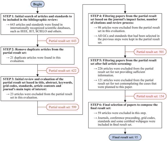
Figure 1.
Schematic diagram of the review process.
In recent years, the photovoltaic generation of electrical energy has become a reality. Consequently, thousands of photovoltaic plants are integrated with the power system in many regions and countries. In the past, the penetration of solar energy was very small compared to conventional generation systems. At present, the usage of photovoltaics’ renewable energy to generate electricity has attracted considerable attention around the world. In the 2021 global status report of sustainable energy [1], solar PV maintained its record-breaking installation rate, adding 175 GW of capacity to reach a cumulative total of around 942 GW. The global capacity additions of large-scale solar power plants increased by around 20%. New installations are driven by economic competitiveness and the necessity to migrate to less-polluting energy sources. Photovoltaic power plants accounted for the majority of new installations in the United States, India, Spain, and France. Figure 2 shows the increase in the global photovoltaic generation in GW from 2018 to 2022. The indicators show an exponential growth over the years. From 2008 to 2015, the increase was 212 GW; in the same period (from 2015 to 2022), the increase was 889 GW (more than four times the increase from the seven previous years). In 2022, the installation of PV power plants was 175 GW higher than the previous year. For comparison, it took more than six years to observe an increase of this magnitude from 2008.
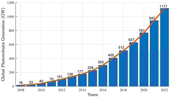
Figure 2.
Renewable energy indicators from 2018 to 2022.
The five countries with the highest installed photovoltaic electricity generation capacity in 2022 are summarized in Figure 3 [1].
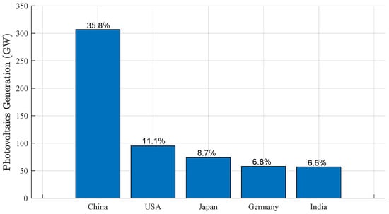
Figure 3.
Top five countries with the greatest installed photovoltaics electricity generation capacity in 2022.
The growth of the large-scale renewable energy generation and its integration into the electricity grid has accelerated, updating the standards and grid codes (GCs) regarding connection requirements. Among the most relevant international organizations that address this topic are the IEEE in the United States, the IEC in Switzerland, and the DKE in Germany [2].
Power systems operators, technical committees, and governmental and research institutions have proposed/established grid interconnection requirements for the penetration of renewable energy sources into electrical power systems, which are undergoing revisions, as these resources represent a relevant portion of the energy matrix. Among them, the following stand out:
- Germany, one of the countries with the highest installation capacity and technology developed in this field, implemented two GCs in 2008 concerning the penetration of renewable energies such as wind [3] and photovoltaic (PV) energy sources [4]. Since then, this has provided a reference for the operation requirements in other countries and the integration of other renewable energy sources. In July 2010, the German GC stipulated that renewable energy source power plants (RESPP) should contribute dynamic support to the power grid; meanwhile, in January 2011, these requirements were extended to the medium-voltage grid [5,6], and the power quality requisites were included for low-voltage PV systems;
- Spain, another leader in the production and installation of PV technology for electrical power generation, is also adopting new requirements for its GCs [7,8];
- Italy has recently adopted an updated version of its GC for distributed generation (DG) systems, which explicitly includes requirements for PV power plants in the CEI 0–16 [9] and CEI 0–21 [10] standards, and in a recent version that was made available in 2016 [11];
- NERC in the United States, whose mission is to ensure the secure operation of the North American power system, oversees eight electrical regions with different system operators (WECC, NPCC, FRCC, MRO, SERC, RF, SPP RE, and Texas RE), following the IEEE recommendations to improve the interconnection of RESPP. The PV integration requirements were addressed in the 2009 IEEE 1547 standard [12], which was revised and updated in 2018 [13];
- The Puerto Rico Electric Power Authority (PREPA) published the technical requirements for interconnecting wind and solar generation to the grid [14,15];
- The two GCs in Australia established by the Australian Energy Market Operator (AEMO) for the Southern Australian grid were updated in 2014 [16,17], while the Western Power (WP) acting as the Transmission System Operator (TSO) for the Western Australian grid revised and updated its GC in 2016 [18]. Although the above-mentioned TSOs are from Australia, they apply different technical regulations;
- Japan FRT requirements were published in 2011 by the Energy and Industrial Development Organization (NEDO) [19]. However, recently, an extensive review of the standards for PV power generation systems connected to the low-voltage grids was carried out, considering the importance of LVRT for single-phase PV power systems during a grid fault [20];
- Other countries have also revised and updated their GCs for the interconnection of renewable energy sources, such as Denmark [21], China [22], and Ireland [23], in addition to European Standards and IEC 61727 [24].
Table 1 shows some of the TSOs, along with their GCs’ last review year.

Table 1.
Grid codes of different countries and their transmission system operators.
In the last decade, several researchers conducted research in this area, including GCs for PV energy integration [5], global standards for the interconnection of renewable energy sources [38], regulations for wind power systems [39], and the integration of other RESPP [40]. Some examples are as follows: [41] presents a brief comparison of the then-new requisites implemented by Germany, the United States, Italy, and Australia to regulate the frequency and voltage behavior during the presence of disturbances in the grid; in 2009, a comprehensive review was published in [42], focusing on the European TSOs, Federal Energy Regulatory Commission standards in the United States, and the TSOs in New Zealand and Canada; likewise, the researchers in [43] studied Spanish and German GCs and the one published by the European TSOs regarding the penetration of wind energy into the electricity grid; the work in [44] compares GCs from North Africa and Spain; lastly, the authors in [45] presented an extensive review of the frequency, voltage, and active and reactive power regulation of the GCs from the United States, Romania, Germany, China, Puerto Rico, and South Africa.
The review presented in this research work reveals the existence of relevant studies published in the last five years dealing with RESPP’s integration into the grid. Studies such as the work presented in [46] discuss the inertia and frequency control strategies in power systems with a high penetration of renewable energy sources, especially PV, and wind. In addition, other researchers have examined how GC’s technical regulations can be tested for compliance and verification purposes. For example, in [47], a comparative study of voltage ride-through (VRT) regulations is presented, in compliance with various GCs. In contrast, the work by [48] provides a review of the control strategies for DG, including generation from wind and PV sources under steady-state and grid disturbance operating conditions. The control proposed in [49] has features that can address connection requirements such as the maximum wind and photovoltaic power extraction under steady-state operations; battery charging and discharging determined by the load and wind power generation conditions; and support for the grid-improving quality requirements, as observed in the results from hardware and simulation, while keeping the THD current level below 5%, as established in the IEEE standard. Another recent work studying the THD limit compliance with the IEEE-1547 standard [13] is presented in [50], in which an adaptive controller is proposed to have a maximum efficiency, achieving a maximum power point tracking (MPPT) under operating uncertainties in PV systems. The proposed controller is able to keep the voltage at the point of common coupling (PCC) and the grid current THD below 3%. Finally, the study in [51] focuses on the connection requirements of PV power plants to achieve MPPT under varying environmental conditions.
The increased interest in research on this subject has led several nations to start establishing operating requirements for renewable energy integration, while others apply additional and more advanced requirements.
The following sections present a comparison (with data available for up to 2022) of the relevant GCs implemented by TSOs in different countries regarding the interconnection of RESPP and the grid. These requisites include VRT, reactive current injection/absorption, active power restoration, frequency stability regulations and active power control, voltage regulation and reactive power control, and energy quality requirements.
This paper is structured as follows: Section 2 introduces the main differences associated with the VRT requirements in the most important grid codes; Section 3 discusses the reactive current injection requirements under LVRT conditions; Section 4 presents a brief explanation of the active power recovery after an LVRT condition; the frequency stability regulation and the active power control stipulated in the different grid codes are summarized in Section 5; Section 6 discusses the voltage regulation and reactive power control; Section 7 presents an overview of the energy quality requirements such as harmonics, voltage unbalances and fluctuations; trends in variable renewable sources’ standardization are included in Section 8; and finally, the conclusion of the paper is presented in Section 9.
2. Voltage Ride-Through (VRT)
Among the most relevant requisites established due to the high penetration of RESPP into the electrical system is the VRT [52]. Decades ago, due to the low integration of renewable energy sources, regulations allowed for these power plants to be disconnected from the grid in the case of nearby faults. However, as RESPPs reach high levels of participation in the power production matrix, shutting them down during faults can worsen the problem and could lead to system instability. In this scenario, most current standards impose VRT as a mandatory requisite for any grid-connected RESPP [53]. The VRT requires RESPP to act as a conventional plant, making it mandatory for it to remain connected to the power system during contingencies and also performing ancillary services, such as reactive current injection/absorption to ensure stability and help restore normal voltage operating conditions after clearing the disturbance. As mentioned in the introduction, there are different types of VRT, which are covered in the following subsections.
2.1. Low-Voltage Ride-Through (LVRT)
The rapid disconnection of RESPP can have an adverse impact on the electrical system’s stability. In response, the GCs of many countries require these plants to remain connected when a disturbance causes the voltage to drop below a certain percentage of the rated voltage (typically 15%) and, in some cases, even reach zero voltage for a specified period. After the disturbance is cleared by the protection system, the RESPP must quickly recover its active and reactive energy production to the pre-fault conditions. Some GCs further stipulate the RESPP to supply the power grid with the necessary reactive current to support the power system voltage, as achieved by conventional synchronous generators [5,8,12,54].
Typically, LVRT requisites are characterized by a graph of voltage vs. time, as shown in Figure 4, which illustrates a generalized LVRT requirement for grid-connected PV systems.
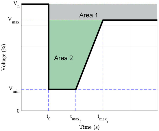
Figure 4.
Generalized limits for LVRT requirements.
Photovoltaic power plants must work continuously when the voltage at the PCC is within Area 1. When a fault causes a voltage drop at instant , the PV system operating status is determined by the duration of the voltage sag: if the voltage remains equal to or above the minimum values defined by Area 2, the PV system must remain connected to provide ancillary services to help maintain stability and normal operation recovery after fault clearance. The values of , , , and differ for each GC and are adjusted based on the grid standards and operating characteristics of each country.
The LVRT requirements of the other countries’ GCs are similar, with minor differences in periods and voltage levels. Based on the regulations of Japan, China, and Denmark, if the voltage drops to 80% below its nominal value, the RESPP must ride through the fault and stay connected to the grid for a specific time; otherwise, it must be disconnected immediately. Similar requisites were imposed in the United Kingdom, the United States, Puerto Rico, and Romania, where the RESPP must stay connected even if the PCC voltage drops to 15% of the nominal value. The Brazilian GC also has an LVRT requiring its generating units to stay connected when the voltage at the PCC drops to a minimum of 20% of its nominal value for 0.5 s, followed by a voltage recovery to 85% of its nominal voltage within 1 s [27].
Table 2.
Parameters of the LVRT in various countries.
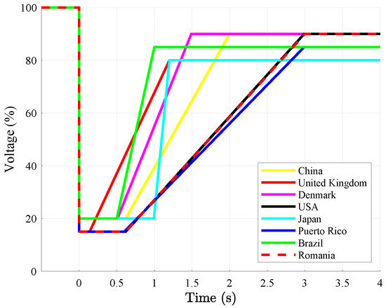
Figure 5.
LVRT requirements in various countries.
2.2. Zero-Voltage Ride-Through (ZVRT)
The ZVRT is a special case of the LVRT because the ZVRT represents an extreme case, where the voltage drops to zero. In this scenario, RESPP must remain connected and provide support to the grid for a specific period [55]. As with LVRT, RESPP must provide support to the voltage recovery and system stability by injecting a reactive current during zero-voltage conditions [56].
Several GCs prohibit the disconnection of RESPP from the grid during a voltage dip, even when the voltage at the PCC drops to zero. However, the specified values for voltage recovery and the maximum time needed to reach these are fairly different from each other [57]. Some of the countries with standards that include this requirement are:
- The Italian GC requires RESPP to ride through faults and stay connected to the power system for 200 ms when the PCC voltage drops to zero. If the PCC voltage recovers to 85% of its rated volue within 1.5 s after the fault is cleared, the PV generation units will remain in a continuous operation without disconnection [11];
- The German GC stipulates the ZVRT for a maximum time of 150 ms, followed by a voltage recovery of 90% of its rated PCC voltage within 1.5 s [5,58];
- The ZVRT requirements in the Spanish GC [26] stipulate that the RESPP must ride through any voltage disturbance (in magnitude and/or phase) at the PCC, whether caused by a three-phase, two-phase to ground, or single-phase short circuits, or any other contingency with the magnitude and duration shown in Figure 6.
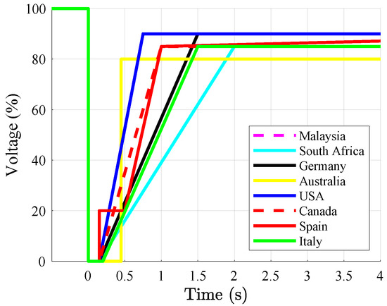 Figure 6. ZVRT requirements implemented in various grid codes.
 - The Australian GC is more restrictive, because RESPP needs to remain connected even if the voltage, after dropping to zero, remains below 80% of the nominal value for up to 450 ms [41].
The ZVRT requirements for GCs from these and other countries are summarized in Table 3 and Figure 6.
Table 3.
Parameters of the ZVRT in various countries.
2.3. High-Voltage Ride-Through (HVRT)
The disconnection of RESPPs during overvoltage makes it impossible for them to contribute to the regulation of reactive power to support the voltage stability of the power system. Therefore, GCs only allow for disconnection when the overvoltage exceeds a certain threshold and a specified time duration [59]. These requisites, known as HVRT, are summarized and compared by country in Table 4 and Figure 7.
Table 4.
Parameters of the HVRT in various countries.
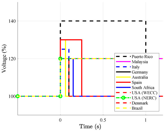
Figure 7.
HVRT requirements in various countries.
Table 4 compares the HVRT parameters applied by different countries in their GCs. Although voltage surge disturbances occur less frequently, they have been regulated similarly to voltage dip disturbances [60]. However, some countries, such as Canada, China, Japan, and Romania, which require LVRT for any RESPP, have not imposed HVRT requisites.
Figure 7 graphically compares the HVRT requirements imposed by Germany, Denmark, Spain, the United States, Australia, Italy, Malaysia, and South Africa. The requirements imposed by PREPA are the strictest among those evaluated, as they require RESPP to stay connected and support the grid in the event of an increase of up to 140% of their nominal voltage for 1 s [15]. This is followed by Spain [7] and Australia [17], with both allowing for an overvoltage of up to 130% of the nominal value before disconnecting from the grid.
The Brazilian GC requires RESPP to withstand an overvoltage of up to 120% for a maximum time of 2.5 s, followed by a reduction in voltage to a maximum value of 110% [27]. Based on these comparisons, it is difficult to find a global VRT requirement, due to the different renewable energy penetration levels in the electrical grid and the different operational parameters established by the national GCs.
These GCs are constantly undergoing revisions, and new and more advanced requirements are established as the share of RESPP in the grid increases.
3. Reactive Current Injection/Absorption
Most of the GCs discussed here require RESPP to ride through faults, as well as provide ancillary services similar to conventional synchronous generators, such as the injection of reactive power into the grid to give support voltage recovery and maintain electrical system stability [61]. The reactive power injection is engaged with the LVRT/ZVRT to increase the voltage and consequently accelerate the power system recovery during and after a fault. Similarly, RESPP must be able to absorb the reactive power during overvoltage in the grid.
The reactive power that must be injected or absorbed is evaluated depending on the drop or rise, respectively, in voltage. For example, according to the German GC [3,4,25], the reactive (q-axis) component of the current is injected/absorbed according to the curve shown in Figure 8. The RESPP should be in continuous operation, without any reactive power support, if the positive sequence voltage () remains within the deadband (±10%) around their nominal value. When the rise or fall in voltage exceeds the deadband, an error signal is sent to the controllers of the inverters to inject/absorb reactive current into/from the power system, respectively. The German GC requires that for every 0.1 p.u. voltage drop/rise, the inverter must inject/absorb 0.2 p.u. reactive current , based on its rated current value. If the voltage drops below 50% of its rated value, 100% of its power plant’s apparent power-rated value must be injected into the electrical grid as the reactive current.
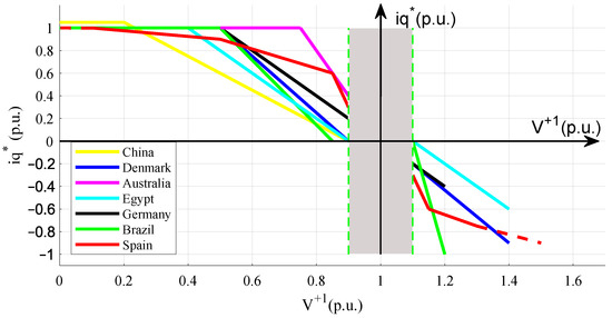
Figure 8.
Dynamic reactive current injection curve as established in different grid codes.
For example, the German GC computes the injected reactive current based on the following equations:
where is the positive sequence voltage at the PCC in per unit, is the rated output current of the PV power plant.
The flowchart that describes the implementation of the equations shown above is presented in [62]. The expression in (1) follows the curve in black for the German GC depicted in Figure 8. The supply of reactive power takes priority over the active power injection; therefore, the photovoltaic panel will only work in the MPPT if the voltage source inverter has a sufficient available capacity [62].
The Spanish grid code requires systems based on renewable energy to inject/absorb reactive power based on the curve shown in Figure 8. However, when the voltage increases beyond 130% of the rated value, the protection relays will require disconnection from the power grid. In addition, once the fault is cleared, the voltage controller will remain engaged for at least 30s after the voltage magnitude returns to the normal operating range [26].
Puerto Rico’s PREPA GC requires RESPP to inject/absorb 5% reactive current for every 1% of voltage variation if the voltage exceeds a deadband of ±15% [15]. Similarly, the Australian GC requires a 4% reactive current supply to the PCC for every 1% voltage reduction [16].
The Brazilian GC requires the RESPP to provide voltage support, injecting reactive power for a positive sequence voltage below 85% and the absorption of reactive power for voltages above 110%, as shown in Figure 8 [27].
Similar requirements for the reactive power support can also be found in the GCs of countries such as China, Denmark, Australia, and Egypt, as shown in Figure 8. The common voltage deadband is between 0.9 and 1.1 p.u. When the drop in voltage reaches below 0.9 p.u., the reactive current injected into the grid is proportional to the voltage drop.
Although most grid codes establish reactive current injection requirements, they fail to establish a clear requirement for the active current injection and limitations [63,64]. During faults, the grid codes allow for operation with zero active power output. However, active power could still be delivered to the power system if the reactive current injection requirements are met and the inverters’ nominal power is not exceeded.
4. Active Power Restoration
After clearing the fault, it is essential to restore active power generation. To this end, the GCs also determine active power ramps for the active power recovery. According to the German GC [25], the active power must be supplied immediately after the fault is cleared and ramped up to the pre-fault condition with a ramp of at least 20%/s of its rated capacity. For systems that become unstable during a fault, a short-term disconnection is allowed. Shortly after this, the power plant must be resynchronized within a maximum time of 2 s after disconnection. After resynchronization, the active power must be supplied immediately and ramped up with a ramp of less than 10%/s of its rated capacity. The Spanish GC [26] requires power plants operating under disturbances to limit their active current within the gray area of Figure 9 (excluding the increment/decrease in the active current due to the frequency control). As can be observed, the active current limitation is a function of , which is the pre-fault active power output. The voltage-dependent active current control is engaged after the fault is cleared, without disconnection, to ensure active power restoration to pre-fault conditions within 250 ms.
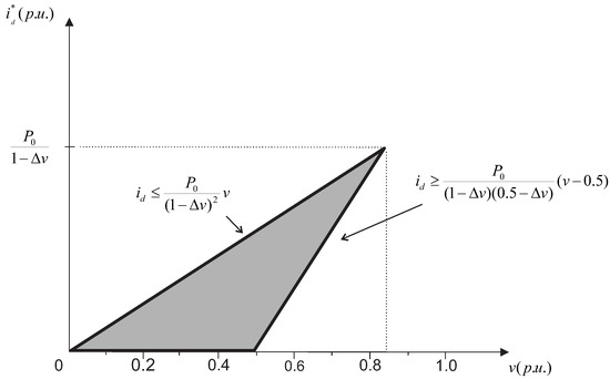
Figure 9.
Spain GC active power limitation during FRT.
Similarly, after the fault has been cleared, the Danish GC requires the RESPP connected to the grid to reach 90% of its PCC-rated voltage and start to supply active power, recovering to 90% of the pre-fault active power in 0.5 s [65].
According to the PREPA requirements, after fault elimination, an immediate increase in the active power with a ramp of at least 10%/s from power plants still connected to the grid is expected [15].
The Brazilian GC determines that power plants’ active power output must recover to at least 85% of the pre-fault operating condition within 4 s after the voltage has recovered to 85% of its rated voltage. The TSO is responsible for adjusting the power recovery ramp depending on the power system operating characteristics [27].
Table 5 provides a comparison between the voltage maximum recovery time and the active power ramps adopted by different countries in their GCs.
Table 5.
Active power recovery thresholds after fault elimination.
5. Frequency Stability Regulations and Active Power Control
The frequency stability of the electrical grid depends on the balance between the active power and load demand at any given time. The aim is to maintain the frequency at typical values of 50 or 60 Hz. Any imbalance between electricity generation and demand load causes a frequency deviation. For this purpose, conventional generators such as hydroelectric or fossil fuel thermoelectric power plants are implemented with speed control to act during an unbalanced operation. The speed regulator performs primary load control and prevents large frequency deviations [66,67]. However, generation units based on renewable energy sources do not have a frequency deviation direct control.
Current generation power plants based on renewable sources are being installed on a large scale, prompting the study of alternative frequency stability methods [68]. For example, international grid codes require renewable generation plants to implement control methods to manage active energy supply in response to frequency variations. Based on a typical frequency vs. active power variation curve (curve in blue), as shown in Figure 10 [57], an increase in frequency should correspond to a decrease in the active power output.
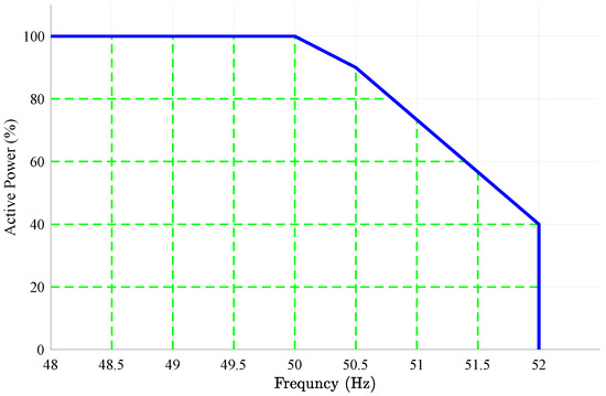
Figure 10.
Typical active power limit response as a function of frequency variations (50 Hz system).
For example, the German GC requires a reduction in the active power output by 40%/Hz when the frequency ranges from 50.2 Hz to 51.5 Hz, as shown in Equation (2).
where is the grid frequency, is the power variation, and p is the available instantaneous power.
However, if the frequency ranges from 47.5 Hz to 50.2 Hz, the generation units must supply the rated active power to the grid. Furthermore, when the frequency becomes less than 47.5 Hz or greater than 51.5 Hz, immediate disconnection of the RESPPs is required [3,4,25].
The Irish grid code requires renewable energy power plants to increase/decrease the active power generated when the frequency reaches values below 49.8 Hz and above 50.2 Hz, respectively. If the frequency remains between 49.8 Hz and 50.2 Hz, the generation units must follow normal operating conditions [23].
The Malaysian grid code requires PV power plants to reduce their active power output by a ratio of 40%/Hz when the frequency increases beyond 50.5 Hz [32].
Some countries have not yet established frequency support regulations, while others, such as South Africa, have implemented these requirements as part of the security tasks of operators of transmission and/or distribution systems [69]. China’s grid code does not require active power-derating when the frequency increases. However, renewable energy plants must support a frequency deviation in the range of 50.2–50.5 Hz. In cases where the frequency increases beyond 50.5 Hz, they must be disconnected from the grid [22].
The Brazilian grid code requires a continuous operation when the grid frequency operates between 58.5 and 62.5 Hz. The continuous operation is also required when the frequency deviates to a range between 56 Hz and 58.5 Hz for a maximum time of 20 s. However, the RESPPs must be immediately disconnected from the grid when the frequency remains at this range beyond 20 s or the frequency drops below 56 Hz. Similarly, the continuous operation is required when the frequency increases to values in the range from 62.5 Hz to 63 Hz for a maximum time of 10 s. However, if the frequency remains at this range beyond 10 s, or if it increases beyond 63 Hz, an immediate disconnection of the power plants must follow [27].
Table 6 presents the minimum and maximum frequency deviation ranges in different countries. If the frequency remains within these limits, no reduction in the active power output is required from the power plants.
Table 6.
Frequency limits as established in the operation of various countries’ electrical grids.
6. Voltage Regulation and Reactive Power Control
As mentioned previously, the high penetration of renewable energy generation can considerably affect voltage stability [70]. Therefore, operators of different electrical systems have included requirements to keep voltages stable and within safe limits when subjected to different operating conditions. These requirements depend on the reactive power support characteristics of the PV inverters and auxiliary devices such as capacitor banks or STATCOMs. PV inverters’ technology, which was initially intended to be connected to the distribution grid, does not generally have these new control features. However, companies such as ABB, SMA, and Danfoss have already upgraded their inverters to implement features such as the control of voltage fluctuations and support for reactive power. Interconnecting large-scale photovoltaic systems to the grid has two main challenges regarding voltage control: (i) the voltage must be within a range defined by the TSO; (ii) large-scale photovoltaic systems must comply with the capability curve given by the TSO. Based on [71], several methods for voltage control in large-scale photovoltaic systems are available, such as reactive power control, voltage regulation, and power factor regulation.
In many grid codes, the power converters should operate within a power factor ranging from 0.95 lagging to 0.95 leading, which is equivalent to approximately ±0.33 p.u. of the reactive power, and a voltage with a maximum deviation of ±0.05 p.u. [72].
However, Germany’s grid code established three operating regions, as portrayed in Figure 11 (each region is represented by the curves in red, blue and black). Every power-generating unit connected to the electrical grid must operate anywhere within one of these regions. The region of operation is determined by the TSO, depending on the location of the PCC. The TSO may even have to establish a different region of operation for a specific generating unit. The system operator can specify, at any time, the value of the reactive power that is to be delivered/absorbed into the power grid within the operating limits.
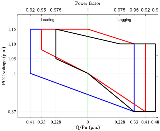
Figure 11.
Basic requirements regarding the supply of reactive energy from renewable plants in Germany. The choice of the 3 regions should be made by the TSO.
The power factor regulation characteristics of the Spanish GC are specified in Figure 12, which establishes the minimum limits of reactive power that any renewable energy power plant should be able to supply. As shown in Figure 12, renewable energy systems must have the capacity to inject/absorb reactive power in a mandatory voltage range p.u. This control feature supports the grid in maintaining the PCC bus voltage within the normal operating voltage range.
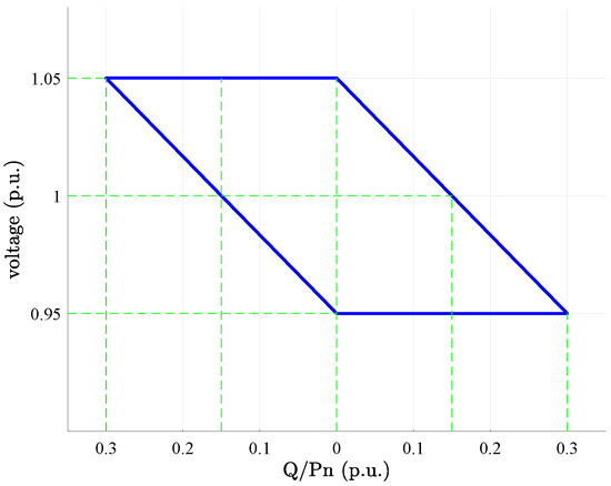
Figure 12.
Basic requirements on the supply of reactive energy from renewable plants according to the Spanish grid code. The region limited by the line in blue represents the area of reactive power regulation for continuous voltage operation.
The Danish standard requires renewable power plants to operate continuously as long as the PCC voltage is between 90% and 105% of the rated value. The continuous operation is limited to at least one hour with a 10% reduction in active power output for voltages in the range from 105% to 110% and 80% to 90%. According to [73], RESPPs must be equipped with a reactive power compensation, following the control band for reactive power, as shown in Figure 13.
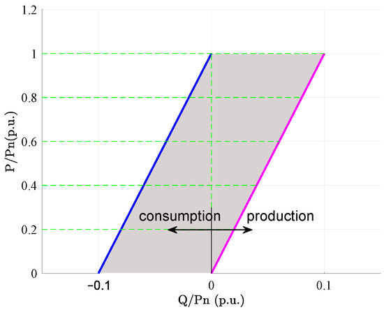
Figure 13.
Basic requirements on the supply of reactive power from renewable plants according to Danish standards. The lines in blue and magenta are the minimum and maximum limits of reactive power variation in relation to active power variation, respectively.
In the Brazilian GC [27], the injection of reactive power into the PCC during steady-state operation must be guaranteed for a given operating voltage range based on the characteristics determined in Figure 14.
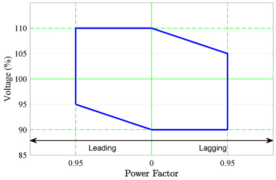
Figure 14.
Requirements to meet the power factor in the voltage range at the PCC. Curve valid for plants with 230 kV or 500 kV PAC voltage. The region limited by the line in blue represents the area of power factor regulation for continuous voltage operation.
In addition, when connecting the generation power plant to the facilities that are under the responsibility of the transmission grid operator, all the necessary resources regarding the steady-state operation with inductive or capacitive power factor at any point within the gray area, as determined by Figure 15 [27], must be provided by the power plant. As a consequence of the reactive power supply requirements at the connection point, PV generation projects usually need to complement the reactive power supply capacity from inverters by installing capacitor banks.
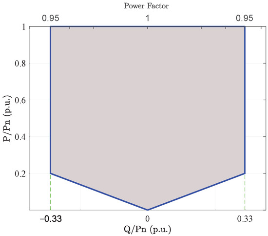
Figure 15.
Range of reactive power generation/absorption at the power plant connection point. The region limited by the line in blue represents the area of reactive power regulation through voltage or power factor control during continuous voltage operation.
Under zero-active-power output conditions, wind or photovoltaic power plants must have the necessary control resources to make their reactive power generation/absorption capacity available to the grid [27].
As explained earlier, reactive power injection can be implemented using either a voltage control or a power factor control. An extra option for setting the reactive power supply is through the remote control of the operating point. System operators have tools to remotely control a bus voltage and the total reactive power output of the entire electrical grid.
7. Energy Quality Requirements
The large-scale integration of renewable energy into the electrical system can lead to problems in the quality of the electrical power supplied to the electrical grid [74]. Therefore, the standards have been upgraded in several countries to target possible solutions to the quality of energy produced by RESPPs. The quality concerns linked to the integration of renewable generation are harmonics, voltage fluctuations, and voltage imbalances [75]. The following subsections focus on these requirements.
7.1. Harmonics
One of the most serious power quality problems is harmonic distortion, which is characterized by voltage and current waves not being purely sinusoidal or of a positive sequence fundamental frequency. A main source of distortion at the generation stage is the use of electronic power devices.
Renewable generation systems use frequency converters to connect with the power grid, and these devices can produce this kind of distortion [76]. As the electricity market pushes to keep increasing levels of power generation from sources connected to the grid using power converters, stricter regulations are established to ensure a low level of harmonic distortion caused by power electronic devices. Power quality is generally analyzed through voltage and current total harmonic distortion (THD) measurements, and can be determined by [77,78]:
where is the amplitude of the fundamental frequency component; are the amplitudes of the harmonic components of an order superior to the fundamental frequency (from 2 to ) [77]. Based on this metric, the IEEE 519-2014, IEEE 1547-2014, and IEC 61727 standards’ [24,79,80,81] current THD limit should not exceed at the PCC. According to the IEC 50160, the voltage THD limit should not exceed 8%, up to the 40th harmonic component. The standards of some countries, including the Brazilian ABNT 16149 [82] and the Malaysian technical regulations [32], also require a THD below 5% at the PCC.
Romanian standards allow for a maximum THD of 3% for photovoltaic and wind power plants connected to the transmission system [83]. Generally, most countries follow the IEEE or IEC standards [84]. The UK adopted the EREC G83, which is remarkably strict. The current harmonic distortion limits based on different standards are shown in Table 7.
Table 7.
Limits of harmonic distortion according to different standards.
In the case of the Brazilian standard, the National Independent System Operator (ONS) [27] uses the voltage THD as the indicator used to evaluate the global power system quality in a steady-state. This indicator is not applied to the transient and short-term phenomena that result in the injection of harmonic currents during operating conditions such as transformer energizing or the start-up of generating units using the frequency converter equipment. Thus, the intervals in which such transient disturbances occur should be discarded from the measurements.
7.2. Voltage Imbalance
A voltage imbalance occurs when the phase voltages differ in magnitude or a phase shift of (). This can be calculated as the ratio of negative to the positive voltage sequence components [85]. In general, world standards have identified that the appropriate voltage unbalance threshold is between 1% and 2% [86]. Voltage unbalance quality problems are monitored for various standards using the voltage unbalance factor (VUF) [27,87,88]:
where and are the positive and negative voltage sequence components at the fundamental frequency, respectively. Usually, the voltage unbalance is a good indicator of the power quality supplied to the electrical system; for this reason, some GCs and standards establish a VUF limit at the PCC, ensuring the injection of a balanced three-phase voltage into the power grid. For example, the IEEE 1547-2014 standard [80] requires that voltage unbalance does not exceed 3%, while the IEC 61850-7-420 standards require DGs to maintain a VUF of less than 2% [24]. Romanian regulations imposed a maximum VUF of 1% at the PCC of photovoltaic and wind power plants [83]. The recommendation given by the UK GC [89], also followed by the Malaysian GC, determines a VUF limit of 2% at the PCC and a voltage unbalance limit of 1.3% at the load [32]. In Canada, the CAN/CSA–C61000–2–2 standard established a maximum VUF of 2% [90,91].
Finally, the Brazilian grid code establishes the performance of voltage unbalance through a comparison of the KS95% indicator, expressing the relationship between the negative and positive voltage sequence components . The maximum voltage unbalance at 2%.
7.3. Fluctuations
Voltage fluctuation is the term used to represent the random, repetitive, or sporadic variation of the effective voltage value. Random and repetitive fluctuations are generally related to the operation of non-linear loads that present a time-varying power consumption, while sporadic fluctuations are related to grid or load maneuvers. Short-term voltage fluctuations, known as flickers, can cause a series of disturbances when propagating through the electrical grid, and cause changes in the intensity of lighting in incandescent lamps [92,93].
The severity of the flicker phenomena is quantified by the Short-Term Flicker Severity Indicator () and by the Long-Term Flicker Severity Indicator (), as described by the International Electrotechnical Commission in IEC 61000-4-15 (Flickermeter—functional and design specifications). The indicator represents the severity of the flicker caused by the voltage fluctuations verified at a continuous period of 10 min, and is calculated from the instantaneous levels of a flickering sensation, according to the following expression:
where corresponds to the level of flicker sensation that was exceeded for x% of the time, resulting from the level classification histogram, calculated as established in IEC-61000-4-15.
The indicator represents the severity of the flickering caused by the voltage fluctuations verified in a continuous period of 2 h, and is calculated from the values according to the following expression:
According to the flicker severity indicators adopted here as a representative of voltage fluctuation, a = 0 indicates that there is no voltage oscillation, and = 1 indicates flicker contamination [94]. The tolerable flicker limits of small- and medium-scale RESPPs connected to the medium voltage are generally considered to be 1.0 and 0.25 for and , respectively [95]. The flicker limits are listed in Table 8.
Table 8.
Flicker limits according to different standards at different voltage levels.
8. Trends in Variable Renewable Sources Standardization
As the share of variable renewable energy sources in the power market increases, observing the requirements of different countries, some trends are notable as new issues are emerging:
- The need for renewable sources to contribute to systemic inertia, with increasingly stringent VRT requirements. For example, grid codes have established rules for the reactive current injection during faults.
- Contribution to voltage control and reactive power supply, using the power converters’ capability—this requirement may need to be implemented even for small projects connected to the low-voltage network.
- Harmonic distortion limits consider the contribution of all sources at the same connection point. Therefore, with the increase in the connection of converters, it can become increasingly difficult for generators to comply, leading to the need to implement filters.
As described previously, the German GC stipulated that RESPP should be able to contribute by providing dynamic support to the grid. In a recent review of the grid code, this requirement was required for application in the medium-voltage grid, and power quality requisites were included even for low-voltage PV systems.
9. Conclusions
This survey paper presents a comprehensive comparison of the requirements for integrating renewable energy sources with the power grid, highlighting the differences between the grid codes and standards established by the operators of electrical systems of different countries. No clear consensus exists to unify the technical requisites for the interconnection of RESPPs to the electrical grid due to various operating methods implemented in different national grids and the varying penetration levels of renewable energy plants. For example, the GCs in some countries enforce the VRT capacity control for each renewable energy source connected to the grid, regardless of power level, while some countries, such as Germany, enforce VRT requirements only for the utility-scale power generation. This distinction may result in lower power quality in some countries’ electrical grids and additional costs for developers and manufacturers of renewable energy plants. The European Renewable Energy Council (EREC) and the European Wind Energy Association (EWEA) request that energy system operators of different national grids improve their interconnection requirements and reflect this in a coherent and harmonized way.
Harmonized integration standards could ensure reliable operation and meet power quality requirements for the vast majority of electrical networks, although this is a difficult task due to the specifics of each power system. Manufacturers of renewable energy systems constantly meet with new challenges when updating their hardware and/or software design to ensure that each entity’s requirements are satisfied. Thus, a generalized set of requirements established in a power grid could reduce costs and standardize the manufacturer requirements, as well as assisting power system operators.
The main objectives of global standard harmonization can be listed as follows:
- Facilitate manufacturing procedures and improvements in renewable energy systems around the world, reducing the total cost;
- Establish common and appropriate standards for the connection of large- or small-scale renewable energy plants into the electrical grid;
- Develop efficient technical requirements that depend on the experiences and backgrounds of various power system operators.
The developed requirements must ensure economic efficiency. However, some technical regulations are considered expensive and are only required when necessary to ensure a steady, safe, and continuous reliable power system operation. In addition, it is possible to bypass grid regulations that are considered expensive when the renewable energy penetration is low. In addition to the penetration level, the requirements for integrating renewable energy must consider the robustness of the power system and the technology implemented in renewable generation power plants. Furthermore, the integration requirements between various electrical areas, countries, and organizations may change in the near future. Standardization would reduce equipment manufacturing costs and simplify the analysis by national system operators. However, each electric power system has its particularities (radial or non-radial systems, low or high penetration of renewables, interconnection or no interconnection with other countries, different standards even within the same country as many regions of operation are interconnected, etc.). Therefore, standardization is still a challenge due to the size and complexity of carrying out a global analysis.
Due to the extensive review presented in this paper, two important ancillary services have been noted to be missing from the standards and GCs, such as the blackstart of RESPP units after a major blackout and spinning reserve usually requested for large synchronous generation units. Future research should also focus on services that are almost exclusively functions of large synchronous generators in the current operating power systems.
Author Contributions
Conceptualization, Y.G.L. and O.C.Z.; data curation, Y.G.L. and O.C.Z.; methodology, Y.G.L. and O.C.Z.; investigation, Y.G.L. and O.C.Z.; formal analysis, Y.G.L., O.C.Z., R.C.N., J.F.d.C.C. and F.A.S.N.; technical review, F.A.S.N., R.C.N. and J.F.d.C.C.; supervision, R.C.N. and F.A.S.N.; funding acquisition, F.A.S.N. All authors have read and agreed to the published version of the manuscript.
Funding
This study was funded by the Brazilian National Council for Scientific and Technological Development (CNPq), grant #307966/2018-6.
Institutional Review Board Statement
Not applicable.
Informed Consent Statement
Not applicable.
Data Availability Statement
Not applicable.
Conflicts of Interest
The authors declare no conflict of interest.
Abbreviations
The following abbreviations are used in this manuscript:
| AEMO | Australian Energy Market Operator |
| DG | Distributed generation |
| FRT | Fault ride-through |
| FRCC | Florida Reliability Coordinating Council |
| GC | Grid Code |
| IEC | International Electrotechnical Commission |
| IEEE | Institute of Electrical and Electronics Engineers |
| MPPT | Maximum Power Point Tracking |
| MRO | Midwest Reliability Organization |
| NEDO | Energy and Industrial Development Organization |
| NPCC | Northeast Power Coordinating Council |
| PV | Photovoltaic |
| PCC | Point of Common Coupling |
| PREPA | Puerto Rico Electric Power Authority |
| RESPP | Renewable energy sources power plant |
| SPP | Southwest Power Pool |
| SERC | State Electricity Regulatory Commission |
| STATCOM | Static Synchronous Compensator |
| Texas RE | Texas Reliability Entity |
| THD | Total Harmonic Distortion |
| TSO | Transmission System Operator |
| VRT | Voltage ride through |
| VUF | Voltage unbalance factor |
| WECC | Western Electricity Coordinating Council |
| Power variation | |
| Grid frequency | |
| Maximum harmonic component | |
| Rated output current of the PV power plant | |
| Computed d-axis active current injected during active power restoration | |
| Computed q-axis reactive current injected during LVRT/ZVRT | |
| p | Available instantaneous power |
| Nominal power | |
| Pre-fault active power output | |
| Level of flicker sensation that was exceeded for x% of the time | |
| Maximum fault end time | |
| Maximum time for active power recovery | |
| Fault starting time | |
| Voltage recovery after a fault | |
| Minimum voltage sag | |
| Positive sequence voltage | |
| Negative sequence voltage | |
| Positive sequence voltage at the PCC in per unit | |
| Amplitude of the fundamental frequency harmonic component |
References
- REN21. Renewables 2022 Global Status Report; REN21: Paris, France, 2022. [Google Scholar]
- Arulkumar, K.; Palanisamy, K.; Vijayakumar, D. Recent advances and control techniques in grid connected PV system—A review. Int. J. Renew. Energy Res. 2016, 6, 1031–1049. [Google Scholar] [CrossRef]
- E.ON-Netz. Requirements for Offshore Grid Connections in the E.ON Netz Network; E.ON Netz Network: Bayreuth, Germany, 2008. [Google Scholar]
- BDEW. Technical Guideline: BDEW (Bundesverband Deutsche Elektrizitäts-und Wasserwirtschaft); Generating Plants Connected to the Medium-Voltage Network, Guideline for Operating Plant’s Connection to and Parallel Operation with the Medium-Voltage Network; BDEW: Berlin, Germany, 2008. [Google Scholar]
- Crăciun, B.I.; Kerekes, T.; Séra, D.; Teodorescu, R. Overview of recent grid codes for PV power integration. In Proceedings of the 13th International Conference on Optimization of Electrical and Electronic Equipment (OPTIM), Brasov, Romania, 24–26 May 2012; pp. 959–965. [Google Scholar] [CrossRef]
- Ruiz, Á. System Aspects of Large Scale Implementation of a Photovoltaic Power Plant. Master’s Thesis, KTH, Stockholm, Sweden, 2011. [Google Scholar]
- García-Sánchez, T.; Gómez-Lázaro, E.; Molina-García, A. A review and discussion of the grid-code requirements for renewable energy sources in Spain. In Proceedings of the International Conference on Renewable Energies and Power Quality (ICREPQ’14), Cordoba, Spain, 8–10 April 2014; pp. 565–570. [Google Scholar] [CrossRef]
- Troester, E. New German grid codes for connecting PV systems to the medium voltage power grid. In Proceedings of the 2nd International Workshop on Concentrating Photovoltaic Power Plants: Optical Design, Production, Grid Connection, Darmstadt, Germany, 9–10 March 2009; pp. 1–4. [Google Scholar]
- CEI 0-16:2012; Technical Rules for the Connection of Active and Passive Users to the HV and MV Networks of Electricity Distribution Companies. Italiano Comitato Elettrotecnico: Milan, Italy, 2012.
- CEI 0-21; Reference Technical Rules for the Connection of Active and Passive Users to the LV Electrical Utilities. Italiano Comitato Elettrotecnico: Milan, Italy, 2014.
- CEI 0-16; Reference Technical Rules for the Connection of Active and Passive Consumers to the HV and MV Electrical Networks of Distribution Company. Italiano Comitato Elettrotecnico: Milan, Italy, 2014.
- IEEE Std 1547.2-2008; IEEE Application Guide for IEEE Std. 1547(TM), IEEE Standard for Interconnecting Distributed Resources with Electric Power Systems. IEEE: Piscataway, NJ, USA, 2009. [CrossRef]
- IEEE Std. 1547-2018 (Revision of IEEE Std. 1547-2003); IEEE Standard for Interconnection and Interoperability of Distributed Energy Resources with Associated Electric Power Systems Interfaces. IEEE: Piscataway, NJ, USA, 2018; pp. 1–138. [CrossRef]
- Puerto Rico Electric Power Authority (PREPA). Minimum Technical Requirements for Photovoltaic Generation (PV) Projects. 2012. Available online: http://www.nrel.gov/docs/fy14osti/57089.pdf (accessed on 16 January 2023).
- Gevorgian, V.; Booth, S. Review of PREPA Technical Requirements for Interconnecting Wind and Solar Generation; Technical Report; National Renewable Energy Lab. (NREL): Golden, CO, USA, 2013. [Google Scholar]
- Australian Energy Market Commission (AEMC). National Electricity Rules Version 63. 2009. Available online: https://www.aemc.gov.au/sites/default/files/content/740997f1-a652-4d22-a3b1-222cc46facf0/Historical-National-Electricity-Rules-v-63.pdf (accessed on 14 December 2022).
- Mokui, H.T.; Masoum, M.A.; Mohseni, M. Review on Australian grid codes for wind power integration in comparison with international standards. In Proceedings of the 2014 Australasian Universities Power Engineering Conference (AUPEC), Perth, Australia, 28 September–1 October 2014; pp. 1–6. [Google Scholar] [CrossRef]
- Western Power. Technical Rules; Western Power: Perth, Australia, 2016. [Google Scholar]
- Kobayashi, H. Fault ride through requirements and measures of distributed PV systems in Japan. In Proceedings of the IEEE Power and Energy Society General Meeting, San Diego, CA, USA, 22–26 July 2012; pp. 1–6. [Google Scholar] [CrossRef]
- Yang, Y.; Enjeti, P.; Blaabjerg, F.; Wang, H. Wide-scale adoption of photovoltaic energy: Grid code modifications are explored in the distribution grid. IEEE Ind. Appl. Mag. 2015, 21, 21–31. [Google Scholar] [CrossRef]
- Energinet. Technical Regulation 3.2.2 for PV Power Plants with a Power Output above 11 kW; Energinet: Fredericia, Denmark, 2016. [Google Scholar]
- Chinese Grid Code GB/T 19964-2012; Technical Requirements for Connecting Photovoltaic Power Station to Power System. ChineseStandard: Singapore, 2013.
- EirGrid. EirGrid Grid Code v6; EirGrid: Dublin, Ireland, 2015. [Google Scholar]
- International Electrotechnical Commission. IEC 61727: Photovoltaic (PV) Systems–Characteristics of the Utility Interface; IEC: London, UK, 2004. [Google Scholar]
- Berndt, H.; Hermann, M.; Kreye, H.; Reinisch, R.; Scherer, U.; Vanzetta, J. TransmissionCode 2007-Network and System Rules of the German Transmission System Operators; VDN e.V.: Berlin, Germany, 2007. [Google Scholar]
- Red Electrica. Technical Requirements for Wind Power and Photovoltaic Installations and Any Generating Facilities Whose Technology Does Not Consist of a Synchronous Generator Directly Connected to the Grid; Red Electrica: Madrid, Spain, 2008. [Google Scholar]
- ONS–Procedimentos de Rede. Módulo 2: Submódulo 2.10: Requisitos Técnicos Mínimos para a Conexão às Instalações de Transmissão; Electrical National Operator: Rio de Janeiro, Brazil, 2022. [Google Scholar]
- EETC. Transmission Grid Code. Solar Energy Plants Grid Connection Code; EETC: Hong Kong, China, 2017. [Google Scholar]
- JEA–Japan Electric Association. Grid-Interconnection Code JEAC 9701-2016; Japan Electric Association: Tokyo, Japan, 2016. [Google Scholar]
- NGET (National Grid Electricity Transmission plc). The Grid Code; Issue 5 Revision 22; NGET: Warwick, UK, 2018. [Google Scholar]
- North American Electric Reliability Corporation. Distributed Energy Resources: Connection Modeling and Reliability Considerations; North American Electric Reliability Corporation: Atlanta, GA, USA, 2017. [Google Scholar]
- ECM–Energy Commission Malaysia. Grid Code for Peninsular Malaysia. 2017. Available online: https://www.gso.org.my/ (accessed on 5 December 2022).
- NERSA–National Energy Regulator of South Africa. Grid Connection Code for Renewable Power Plants (RPPs) Connected to the Electricity Transmission System (TS) or the Distribution System (DS) in South Africa. 2016. Available online: www.nersa.org.za (accessed on 28 November 2022).
- EDF–Électricité de France. Référentiel Technique HTB Relatif Aux Prescriptions Techniques de Conception et de Fonctionnement Pour le Raccordement D’une Installation de Production D’énergie électrique au Réseau Public HTB≥50 kV des Zones Non Interconnectées; EDF–Électricité de France: Paris, France, 2018. [Google Scholar]
- TPNZ–Transpower New Zealand. Electricity Industry Participation Code; Transpower New Zealand: Wellington, New Zealand, 2017. [Google Scholar]
- HydroQuébec. Transmission Provider Technical Requirements for the Connection of Power Plants to the Hydro-Québec Transmission System; HydroQuébec: Montreal, QC, Canada, 2009. [Google Scholar]
- EC–European Commission. Establishing a Network Code on Requirements for Grid Connection of Generators; European Commission: Brussels, Belgium, 2016. [Google Scholar]
- Rangarajan, S.S.; Collins, E.R.; Fox, J.C.; Kothari, D.P. A survey on global PV interconnection standards. In Proceedings of the 2017 IEEE Power and Energy Conference at Illinois (PECI), Piscataway, NJ, USA, 16–20 July 2017; pp. 1–8. [Google Scholar] [CrossRef]
- Mohseni, M.; Islam, S.M. Review of international grid codes for wind power integration: Diversity, technology and a case for global standard. Renew. Sustain. Energy Rev. 2012, 16, 3876–3890. [Google Scholar] [CrossRef]
- Rodrigues, E.; Osório, G.; Godina, R.; Bizuayehu, A.; Lujano-Rojas, J.; Catalão, J. Grid code reinforcements for deeper renewable generation in insular energy systems. Renew. Sustain. Energy Rev. 2016, 53, 163–177. [Google Scholar] [CrossRef]
- Al-Shetwi, A.Q.; Sujod, M.Z.; Ramli, N.L. A review of the fault ride through requirements in different grid codes concerning penetration of PV system to the electric power network. ARPN J. Eng. Appl. Sci. 2015, 10, 9906–9912. [Google Scholar]
- Tsili, M.; Papathanassiou, S. A review of grid code technical requirements for wind farms. IET Renew. Power Gener. 2009, 3, 308–332. [Google Scholar] [CrossRef]
- Shah, R.; Mithulananthan, N.; Bansal, R.; Ramachandaramurthy, V. A review of key power system stability challenges for large-scale PV integration. Renew. Sustain. Energy Rev. 2015, 41, 1423–1436. [Google Scholar] [CrossRef]
- Loudiyi, K.; Berrada, A.; Svendsen, H.G.; Mentesidi, K. Grid code status for wind farms interconnection in Northern Africa and Spain: Descriptions and recommendations for Northern Africa. Renew. Sustain. Energy Rev. 2018, 81, 2584–2598. [Google Scholar] [CrossRef]
- Cabrera-Tobar, A.; Bullich-Massagué, E.; Aragüés-Peñalba, M.; Gomis-Bellmunt, O. Review of advanced grid requirements for the integration of large scale photovoltaic power plants in the transmission system. Renew. Sustain. Energy Rev. 2016, 62, 971–987. [Google Scholar] [CrossRef]
- Fernández-Guillamón, A.; Gómez-Lázaro, E.; Muljadi, E.; Molina-García, Á. Power systems with high renewable energy sources: A review of inertia and frequency control strategies over time. Renew. Sustain. Energy Rev. 2019, 115, 109369. [Google Scholar] [CrossRef]
- Al-Shetwi, A.Q.; Sujod, M.Z.; Blaabjerg, F.; Yang, Y. Fault ride-through control of grid-connected photovoltaic power plants: A review. Sol. Energy 2019, 180, 340–350. [Google Scholar] [CrossRef]
- Meral, M.E.; Çelík, D. A comprehensive survey on control strategies of distributed generation power systems under normal and abnormal conditions. Annu. Rev. Control 2019, 47, 112–132. [Google Scholar] [CrossRef]
- Bhattacharyya, S.; Puchalapalli, S.; Singh, B. Operation of Grid-Connected PV-Battery-Wind Driven DFIG Based System. IEEE Trans. Ind. Appl. 2022, 58, 6448–6458. [Google Scholar] [CrossRef]
- Bhunia, M.; Subudhi, B.; Ray, P.K. Design and Real-Time Implementation of Cascaded Model Reference Adaptive Controllers for a Three-Phase Grid-Connected PV System. IEEE J. Photovoltaics 2021, 11, 1319–1331. [Google Scholar] [CrossRef]
- Vanti, S.; Bana, P.R.; D’Arco, S.; Amin, M. Single-Stage Grid-Connected PV System With Finite Control Set Model Predictive Control and an Improved Maximum Power Point Tracking. IEEE Trans. Sustain. Energy 2022, 13, 791–802. [Google Scholar] [CrossRef]
- Tarafdar Hagh, M.; Khalili, T. A review of fault ride through of PV and wind renewable energies in grid codes. Int. J. Energy Res. 2019, 43, 1342–1356. [Google Scholar] [CrossRef]
- Ayodele, T.; Jimoh, A.; Munda, J.; Agee, J. Challenges of grid integration of wind power on power system grid integrity: A review. Int. J. Renew. Energy Res. 2020, 2. [Google Scholar] [CrossRef]
- Yang, Y.; Enjeti, P.; Blaabjerg, F.; Wang, H. Suggested grid code modifications to ensure wide-scale adoption of photovoltaic energy in distributed power generation systems. In Proceedings of the 2013 IEEE Industry Applications Society Annual Meeting, Lake Buena Vista, FL, USA, 6–11 October 2013; pp. 1–8. [Google Scholar] [CrossRef]
- Zhang, Z.; Yang, Y.; Ma, R.; Blaabjerg, F. Zero-voltage ride-through capability of single-phase grid-connected photovoltaic systems. Appl. Sci. 2017, 7, 315. [Google Scholar] [CrossRef]
- Sutherland, P.E. Ensuring stable operation with grid codes: A look at Canadian wind farm interconnections. IEEE Ind. Appl. Mag. 2015, 22, 60–67. [Google Scholar] [CrossRef]
- Al-Shetwi, A.Q.; Sujod, M.Z. Grid-connected photovoltaic power plants: A review of the recent integration requirements in modern grid codes. Int. J. Energy Res. 2018, 42, 1849–1865. [Google Scholar] [CrossRef]
- Neumann, T.; Erlich, I. Modelling and control of photovoltaic inverter systems with respect to German grid code requirements. In Proceedings of the 2012 IEEE Power and Energy Society General Meeting, San Diego, CA, USA, 22–26 July 2012; pp. 1–8. [Google Scholar] [CrossRef]
- Liu, G.; Hu, J.; Tian, G.; Xu, L.; Wang, S. Study on high voltage ride through control strategy of PMSG-based wind turbine generation system with SCESU. J. Eng. 2019, 2019, 4257–4260. [Google Scholar] [CrossRef]
- Haidar, A.M.; Julai, N. An improved scheme for enhancing the ride-through capability of grid-connected photovoltaic systems towards meeting the recent grid codes requirements. Energy Sustain. Dev. 2019, 50, 38–49. [Google Scholar] [CrossRef]
- Oon, K.H.; Tan, C.; Bakar, A.; Che, H.S.; Mokhlis, H.; Illias, H. Establishment of fault current characteristics for solar photovoltaic generator considering low voltage ride through and reactive current injection requirement. Renew. Sustain. Energy Rev. 2018, 92, 478–488. [Google Scholar] [CrossRef]
- Neves, F.A.; Carrasco, M.; Mancilla-David, F.; Azevedo, G.M.; Santos, V.S. Unbalanced grid fault ride-through control for single-stage photovoltaic inverters. IEEE Trans. Power Electron. 2015, 31, 3338–3347. [Google Scholar] [CrossRef]
- Weise, B. Impact of K-factor and active current reduction during fault-ride-through of generating units connected via voltage-sourced converters on power system stability. IET Renew. Power Gener. 2015, 9, 25–36. [Google Scholar] [CrossRef]
- Zheng, Q.; Li, J.; Ai, X.; Wen, J.; Fang, J. Overview of grid codes for photovoltaic integration. In Proceedings of the 2017 IEEE Conference on Energy Internet and Energy System Integration (EI2), Beijing, China, 26–28 November 2017; pp. 1–6. [Google Scholar] [CrossRef]
- Preda, T.N.; Uhlen, K.; Nordgård, D.E. An overview of the present grid codes for integration of distributed generation. In Proceedings of the CIRED 2012 Workshop: Integration of Renewables into the Distribution Grid, Lisbon, Portugal, 29–30 May 2012; pp. 1–4. [Google Scholar] [CrossRef]
- Dreidy, M.; Mokhlis, H.; Mekhilef, S. Inertia response and frequency control techniques for renewable energy sources: A review. Renew. Sustain. Energy Rev. 2017, 69, 144–155. [Google Scholar] [CrossRef]
- Sedighizadeh, M.; Esmaili, M.; Mousavi-Taghiabadi, S.M. Optimal energy and reserve scheduling for power systems considering frequency dynamics, energy storage systems and wind turbines. J. Clean. Prod. 2019, 228, 341–358. [Google Scholar] [CrossRef]
- Stram, B.N. Key challenges to expanding renewable energy. Energy Policy 2016, 96, 728–734. [Google Scholar] [CrossRef]
- Sewchurran, S.; Davidson, I.E. Guiding principles for grid code compliance of large utility scale renewable power plant integration onto South Africa’s transmission/distribution networks. In Proceedings of the 2016 IEEE International Conference on Renewable Energy Research and Applications (ICRERA), Birmingham, UK, 20–23 November 2016; pp. 528–537. [Google Scholar] [CrossRef]
- Hossain, J.; Pota, H.R. Robust Control for Grid Voltage Stability: High Penetration of Renewable Energy: Interfacing Conventional and Renewable Power Generation Resources (Power Systems); Springer: Berlin/Heidelberg, Germany, 2014. [Google Scholar]
- Morjaria, M.; Anichkov, D.; Chadliev, V.; Soni, S. A grid-friendly plant: The role of utility-scale photovoltaic plants in grid stability and reliability. IEEE Power Energy Mag. 2014, 12, 87–95. [Google Scholar] [CrossRef]
- Espinoza, N.; Bongiorno, M.; Carlson, O. Grid code testing of full power converter based wind turbines using back-to-back voltage source converter system. In Proceedings of the EWEA Annual Event 2013 Conference Proceedings, Vienna, Austria, 4–7 February 2013. [Google Scholar]
- Energinet. dk. Grid Connection of Wind Turbine to Network with Voltages above 100 kV; Energinet.dk: Fredericia, Danmark, 2004. [Google Scholar]
- Liang, X. Emerging power quality challenges due to integration of renewable energy sources. IEEE Trans. Ind. Appl. 2016, 53, 855–866. [Google Scholar] [CrossRef]
- Anees, A.S. Grid integration of renewable energy sources: Challenges, issues and possible solutions. In Proceedings of the 2012 IEEE 5th India International Conference on Power Electronics (IICPE), Delhi, India, 6–8 December 2012; pp. 1–6. [Google Scholar] [CrossRef]
- Jaalam, N.; Rahim, N.; Bakar, A.; Tan, C.; Haidar, A.M. A comprehensive review of synchronization methods for grid-connected converters of renewable energy source. Renew. Sustain. Energy Rev. 2016, 59, 1471–1481. [Google Scholar] [CrossRef]
- Memon, M.A.; Mekhilef, S.; Mubin, M.; Aamir, M. Selective harmonic elimination in inverters using bio-inspired intelligent algorithms for renewable energy conversion applications: A review. Renew. Sustain. Energy Rev. 2018, 82, 2235–2253. [Google Scholar] [CrossRef]
- Jannesar, M.R.; Sedighi, A.; Savaghebi, M.; Anvari-Moghaddam, A.; Guerrero, J.M. Optimal probabilistic planning of passive harmonic filters in distribution networks with high penetration of photovoltaic generation. Int. J. Electr. Power Energy Syst. 2019, 110, 332–348. [Google Scholar] [CrossRef]
- IEEE Std 519-1992; IEEE Recommended Practices and Requirements for Harmonic Control in Electrical Power Systems. IEEE: Piscataway, NJ, USA, 1993; pp. 1–100.
- IEEE Std 1547a-2014 (Amendment to IEEE Std 1547-2003); IEEE Standard for Interconnecting Distributed Resources with Electric Power Systems—Amendment 1. IEEE: Piscataway, NJ, USA, 2014; pp. 1–16.
- Cho, N.; Lee, H.; Bhat, R.; Heo, K. Analysis of Harmonic Hosting Capacity of IEEE Std. 519 with IEC 61000-3-6 in Distribution Systems. In Proceedings of the 2019 IEEE PES GTD Grand International Conference and Exposition Asia (GTD Asia), Bangkok, Thailand, 19–23 March 2019; pp. 730–734. [Google Scholar] [CrossRef]
- Figueira, H.H.; Hey, H.L.; Schuch, L.; Rech, C.; Michels, L. Brazilian grid-connected photovoltaic inverters standards: A comparison with IEC and IEEE. In Proceedings of the 2015 IEEE 24th International Symposium on Industrial Electronics (ISIE), Rio de Janeiro, Brazil, 3–5 June 2015; pp. 1104–1109. [Google Scholar] [CrossRef]
- RAE–Regulatory Authority for Energy. Technical Transmission Grid Code of the Romanian Power System. 2014. Available online: www.anre.ro (accessed on 8 December 2022).
- Gao, D.W.; Muljadi, E.; Tian, T.; Miller, M.; Wang, W. Comparison of Standards and Technical Requirements of Grid-Connected Wind Power Plants in China and the United States; Technical Report; National Renewable Energy Lab. (NREL): Golden, CO, USA, 2016. [Google Scholar] [CrossRef]
- Shang, L.; Jiabing, H.; Xiaoming, Y.; Huang, Y. Improved virtual synchronous control for grid-connected VSCs under grid voltage unbalanced conditions. J. Mod. Power Syst. Clean Energy 2019, 7, 174–185. [Google Scholar] [CrossRef]
- Ghassemi, F.; Perry, M. Review of Voltage Unbalance Limit in the GB Grid Code CC. 6.1.5 (b); National Grid: London, UK, 2014. [Google Scholar]
- Kim, Y.J. Development and analysis of a sensitivity matrix of a three-phase voltage unbalance factor. IEEE Trans. Power Syst. 2018, 33, 3192–3195. [Google Scholar] [CrossRef]
- Neukirchner, L.; Görbe, P.; Magyar, A. Voltage unbalance reduction in the domestic distribution area using asymmetric inverters. J. Clean. Prod. 2017, 142, 1710–1720. [Google Scholar] [CrossRef]
- ENA–Energy Networks Association. Engineering Recommendation p29: Planning Limits for Voltage Unbalance in the United Kingdom; Energy Networks Association: London, UK, 1990. [Google Scholar]
- CSA Group. CAN/CSA-C61000-2-2-04 (R2014)-Electromagnetic Compatibility (EMC)-Part 2-2: Environment-Compatibility Levels for Low-Frequency Conducted Disturbances and Signalling in Public Low–Voltage Power Supply Systems; CSA Group: Toronto, ON, Canada, 1997. [Google Scholar]
- Papachristou, A.C.; Awad, A.S.; Turcotte, D.; Wong, S.; Prieur, A. Impact of DG on Voltage Unbalance in Canadian Benchmark Rural Distribution Networks. In Proceedings of the 2018 IEEE Electrical Power and Energy Conference (EPEC), Toronto, ON, Canada, 10–11 October 2018; pp. 1–6. [Google Scholar] [CrossRef]
- IEC International Standard. IEC 61000-4-15; Flickermeter, Functional and Design Specifications. International Electrotechnical Commission: Geneva, Switzerland, 1997.
- O’Driscoll, E.; O’Donnell, G.E. Industrial power and energy metering–a state-of-the-art review. J. Clean. Prod. 2013, 41, 53–64. [Google Scholar] [CrossRef]
- Siülsüpür, M.; Türkay, B.E. Flicker source detection methods based on IEC 61000-4-15 and signal processing techniques—A review. Balk. J. Electr. Comput. Eng. 2015, 3. [Google Scholar] [CrossRef]
- Macii, D.; Petri, D. Rapid Voltage Change Detection: Limits of the IEC Standard Approach and Possible Solutions. IEEE Trans. Instrum. Meas. 2019, 69, 382–392. [Google Scholar] [CrossRef]
Disclaimer/Publisher’s Note: The statements, opinions and data contained in all publications are solely those of the individual author(s) and contributor(s) and not of MDPI and/or the editor(s). MDPI and/or the editor(s) disclaim responsibility for any injury to people or property resulting from any ideas, methods, instructions or products referred to in the content. |
© 2023 by the authors. Licensee MDPI, Basel, Switzerland. This article is an open access article distributed under the terms and conditions of the Creative Commons Attribution (CC BY) license (https://creativecommons.org/licenses/by/4.0/).