Abstract
Consequent pole permanent magnet (CPPM) machines can improve the ratio of average torque to PM volume, but suffer from more serious armature reactions. In this paper, the variations of electromagnetic performance of surface-mounted PM (SPM), conventional CPPM machines, and pole-shaped CPPM machines with armature reaction at currents up to 5 times overload are analyzed and compared. The flux densities, flux linkages, back EMFs, inductances, torque characteristics, and demagnetization withstand capabilities are analyzed by the finite element method (FEM) and frozen permeability method. It is validated that the third order harmonics in inductances for CPPM machines tend to be reduced as current rises since the saturation in iron pole is prone to reducing the saliency effect. But the armature reaction tends to result in the increase of torque ripple components for all the machines. It is also found that the overall torque ripple of asymmetric pole-shaped machine tends to increase significantly under overload conditions. On the contrary, the symmetrical pole-shaped machine can maintain a relatively stable torque ripple under overload conditions which is similar to the SPM counterpart. Additionally, due to the large armature reactions, CPPM machines suffer from weaker demagnetization withstand capabilities and weaker overload capabilities than their SPM counterparts. Four CPPM prototypes with and without pole shaping are tested to confirm the FEM analysis.
1. Introduction
As an important way of converting electrical energy to mechanical energy, electrical machines have drawn much attention due to their zero-emission. The mechanical energy quality is directly determined by electrical machines. For better use of energy, consequent pole permanent magnet (CPPM) machine is widely investigated in recent years due to its high torque density and low cost. In CPPM machines, alternate magnet poles are replaced by iron poles. It has been pointed out that CPPM machines can largely save the amount of magnet and improve the ratio of average torque to magnet volume [1,2]. However, CPPM machines also have some problems, including high armature reaction and large torque ripple.
Due to lower flux reluctance along the PM flux path and thus higher inductance, the armature reactions in CPPM machines are more serious than those in conventional surface-mounted PM (SPM) counterparts, which will inevitably lead to saturation problems and result in performance variations. Refs. [3,4] found that consequent pole interior PM machines have lower overload capacity than conventional pole IPM machines but without deep analysis. In [5], the influence of armature current on the radial force in eccentric CPPM machines was investigated. A subdomain model was developed in [6] to predict the armature reaction field in dual-stator CPPM machines. But the saturation is ignored in the analytical model. Obviously, a high armature reaction will inevitably affect the torque ripples for CPPM machines but hitherto without any comprehensive studies.
As for the suppression of torque ripple, pole shaping methods have been analyzed in literatures. Based on an outer rotor CPPM machine with high pole numbers, ref. [7] proposed a non-uniform air-gap profiling method that can reduce the torque ripple. A six-phase machine was optimized to improve torque performance in [8]. However, the torque ripple of the optimized machine is still larger than that of its SPM counterpart. The pole-end barrier shape can also be optimized to reduce torque ripple as reported in [4,9]. The 3rd order harmonic is utilized in the magnet pole shaping in CPPM machines [10] and the torque ripple can be suppressed. Refs. [11,12] validated that the asymmetric pole shaping method is effective in suppressing the torque ripple for a 12-slot/8-pole (12s8p) CPPM machine. This is followed by the investigation of the influence of slot/pole number combinations as demonstrated in [13], where the CPPM machines are divided into two groups according to the odd/even slot number for one phase in a submachine. It has been validated that the asymmetric pole shaping is more suitable for CPPM machines with odd slot number per phase in a submachine while the symmetrical pole shaping is more suitable for CPPM machines with even slot number per phase in a submachine. However, the influences of armature reaction on pole-shaped CPPM machines are not fully investigated in all of these literature. To improve the mechanical energy quality, this paper analyzes the influence of armature reaction on CPPM machines in detail.
In this paper, focusing on the electromagnetic energy conversion process, the performances, including flux density, flux linkage, back EMF, inductance, torque, and demagnetization withstand capability under different currents will be analyzed with the finite element method (FEM). Frozen permeability method will be used to obtain the on-load performances and torque components. The variation of waveforms, harmonics, and contour in these performances will be investigated. In addition, the influence of armature reaction on pole-shaped machines will be analyzed, which shows that the torque ripple of the asymmetric pole-shaped machine will rise significantly as current increases, while that of the symmetrical pole-shaped machine can be relatively stable.
This paper is arranged as follows. Firstly, the analyzed models, including conventional SPM, conventional CPPM (CCPPM), and pole-shaped CPPM (PSCPPM) machines, will be introduced in Section 2. Machines with 12s8p and 12s10p are selected in this paper for analysis, which covers two groups of CPPM machines that have different performances as has been clarified in [13]. In Section 3, the influences of armature reaction on CCPPM are analyzed and compared with their SPM counterparts. Then, the performances of PSCPPM machines will be investigated and discussed in Section 4. This is followed by the experimental verification with four prototypes, i.e., 12s8p-CCPPM, 12s8p-PSCPPM, 12s10p-CCPPM, and 12s10p-PSCPPM machines in Section 5. Finally, important conclusions will be highlighted in Section 6.
2. CPPM Model and Machine Topologies
2.1. CPPM Model
As shown in Figure 1, the flux circuits for SPM and CPPM machines are demonstrated. Thus, the magnet fluxes for SPM machine φSPM and CPPM machine φCPPM can be obtained:
where FcPM is the magnetic magnetomotive force (MMF) of PMs, RAG and Rstator are the flux reluctances in air-gap and stator, RPM and RPM’ are the flux reluctances in the magnet for SPM and CPPM machines, respectively, and Rrotor and Rrotor’ are the flux reluctances in the rotor core for SPM and CPPM machines, respectively.
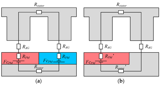
Figure 1.
Flux circuit models for SPM and CPPM machines. (a) SPM. (b) CPPM.
Commonly, the flux reluctances in stator and rotor iron can be treated as 0 in the flux circuit models since the saturation can be neglected. It has been proven that although the magnetic MMF for CPPM machines is half of that for SPM machines, the flux reluctance is also almost halved [2]. Consequently, the magnet fluxes for SPM machine φSPM and CPPM machine φCPPM are almost the same. However, when the saturation cannot be neglected, the flux reluctances in stator and rotor iron need to be considered, which will inevitably result in the drop of magnetic flux for both SPM and CPPM machines. Depending on the saturation level, the characteristics of the flux linkages under different load conditions will be different for SPM and CPPM machines. Generally, the saturation levels for CPPM machines are higher due to the higher armature reaction and inductance.
Apart from the fluxes produced by PMs, the inductances for CPPM machines are also different from those of SPM machines. The average inductance value for CPPM machine LCPPM is also larger than that of SPM counterpart LSPM, which can be explained by the following equations:
where Nc is the number of turns per winding. Obviously, due to the lower flux reluctance for CPPM machines, the inductance value is higher, which will lead to a larger armature reaction and in turn lead to a relatively large variation range in inductance.
In addition, it has been validated in [13] that the harmonic components in winding inductance for CPPM machines are highly dependent on the slot/pole number combination, namely, the inductance contains odd order harmonics when there is an odd slot number for one phase in a submachine, while the inductance only contains even order harmonics when there is an even slot number for one phase in a submachine.
Since saturation due to armature reaction will lead to changes in flux and inductance, the output torque will also be affected. The overall output torque Te can be considered as being made up of three components: PM excitation torque TPM, reluctance torque Tr, and cogging torque Tcog and can be expressed by [14,15,16]:
where ψdPM and ψqPM are the dq-axes PM fluxes, id and iq are the dq-axis currents, Ld and Lq are the dq-axes inductances, p is the pole pair number, Wr(θ) is the magnetic co-energy solely due to PM flux linkage and amplitude invariant transformation matrix is used. It is worth mentioning that the cogging torque Tcog is a function of flux density and geometry parameters [13], which are not the focus of this paper. Thus, it is not expanded. It is clear that the PM flux linkage will affect the PM torque TPM and the inductance will affect the reluctance torque Tr. The saturation will also influence on-load cogging torque [17]. It is worth noting that although (5) is complex enough, it still cannot predict the on-load torque ripple precisely even with on-load values of flux linkages and inductances. This is because the dq-axis flux linkages and inductances are calculated from the integral of flux densities under wound teeth area produced by PMs and unit current, respectively, which cannot describe the influence of local saturations completely. However, local saturations will definitely lead to torque ripples and are quite common under on-load conditions. Therefore, the influences of armature reaction on magnetic flux, inductance, and torque will be comprehensively analyzed by FEM with the frozen permeability method in the following text.
2.2. Machine Topologies
According to the slot/pole number combinations, the CPPM machines can be divided into two groups [14]. Therefore, in this paper, a CPPM machine with an odd slot number for one phase in a submachine, 12-slot/8-pole (12s8p), and a CPPM machine with an even slot number for one phase in a submachine, 12s10p, are selected for demonstration, which is denoted as conventional CPPM (CCPPM) machines, i.e., 12s8p-CCPPM and 12s10p-CCPPM machines. As shown in Figure 2, to obtain the maximum average torque, the PM pole arc ratios, i.e., the ratio of PM pole arc to pole pitch, for both 12s8p and 12s10p machines are changed under a fixed amount of magnet and finally set as 1.2. For comparison, the corresponding SPM machines will also be analyzed, namely 12s8p-SPM and 12s10p-SPM machines. To further investigate the influence of armature reaction on pole shaping effect, the 12s8p CPPM machine with asymmetric pole shape and the 12s10p CPPM machine with symmetrical pole shape are also selected for investigation, which will be denoted as pole-shaped CPPM (PSCPPM) machines, i.e., 12s8p-PSCPPM and 12s10p-PSCPPM machines. With the key parameters summarized in Table 1, the relationships for these models are illustrated in Figure 3. It is worth noting that the magnet volumes for CPPM machines are the same and are half of SPM machines. Besides, the temperature of PM is set as 80 °C in analysis of demagnetization performances while it is 20 °C for other performances.
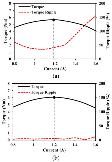
Figure 2.
Models for analysis in this paper. (a) Torque characteristics for 12s8p CCPPM machine. (b) Torque characteristics for 12s10p CCPPM machine.

Table 1.
Key Design Parameters of Analyzed Machines.
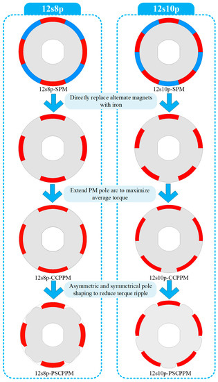
Figure 3.
Models for analysis in this paper.
3. Influence of Armature Reaction on CPPM Machines
In this section, the focus is on the influence of armature reaction on CCPPM and SPM machines. Therefore, 12s8p-SPM, 12s8p-CCPPM, 12s10p-SPM, and 12s10p-CCPPM are analyzed and compared, while the 12s8p-PSCPPM and 12s10p-PSCPPM will be analyzed in the next section to demonstrate the influence of armature reaction on pole shaping effect.
The frozen permeability method [18] in JMAG is employed to obtain the on-load performances, including flux density, flux linkage, back EMF, inductance, and torque components. This method can obtain the onload performances easily but is very time-consuming. The calculation process can be briefly described as follows:
- (1)
- The model runs under the load condition and the permeability of each mesh element in iron part, including stator iron and rotor iron, at each time step is recorded.
- (2)
- Then, the materials with those recorded permeabilities can be treated as linear at each step and the model will be run again without current to obtain the on-load cogging torque, flux density, PM flux linkage, and back EMF.
- (3)
- With the same recorded permeabilities, the model will be run without magnets to obtain the on-load reluctance torque. After that, the on-load PM torque can be obtained by making the difference between the total torque and the other two components.
- (4)
- With the same recorded permeabilities, unit direct current in one phase winding is injected to obtain the flux linkage in each phase. Then, the inductances can be obtained from (6) in abc-frame. Since the permeabilities are recorded under saturated conditions, the calculated results are the inductances under saturated conditions. Finally, the inductances in abc-frame will be transferred to dq-axes in Matlab.where Iunit is the unit current, namely 1A, Ψ and L are the corresponding flux linkage and inductance.
Several armature reaction conditions are selected as given in Table 2. Since the reluctance torques for CPPM machines are too small to be utilized the current advanced angle is set as 0 for all the conditions.

Table 2.
Key Design Parameters of Analyzed Machines.
3.1. Magnetic Flux Density Characteristics
With the frozen permeability method, the PM magnetic flux density in air-gap under open circuit and on-load conditions are obtained as shown in Figure 4 and Figure 5. Clearly, as the current increases, the deformation of the waveform becomes more severe and the amplitudes of fundamental flux densities show a decreasing trend. It can also be found that the decrease of CCPPM is more pronounced than that of SPM, which is due to the larger armature reaction that caused saturation for CCPPM machines.
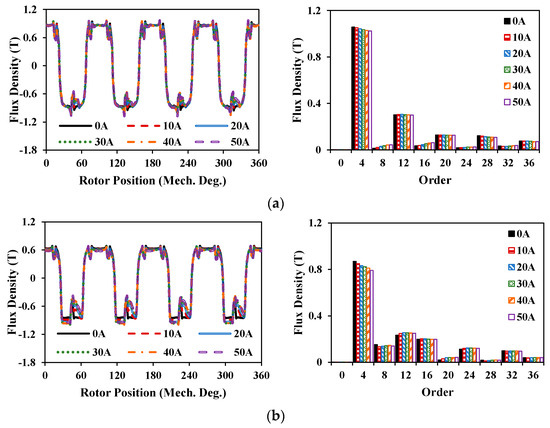
Figure 4.
Air-gap flux densities and spectra for 12s8p machines. (a) 12s8p-SPM. (b) 12s8p-CCPPM.
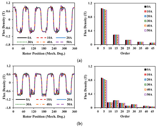
Figure 5.
Air-gap flux densities and spectra for 12s8p machines. (a) 12s10p-SPM. (b) 12s10p-CCPPM.
The equal potential distributions for these machines under different current conditions are demonstrated in Figure 6, Figure 7, Figure 8 and Figure 9. It can be found that the PM fluxes can be shifted with the current increase for all machines. Additionally, the fluxes of armature currents are mainly concentrated on several teeth under light load conditions and tend to distribute on more teeth as the current rises.
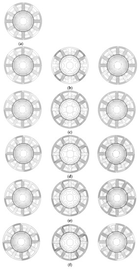
Figure 6.
Equal potential distributions for 12s8p-SPM. (from left to right: PM only, armature current only, overall) (a) 0A. (b) 10A (c) 20A. (d) 30A. (e) 40A. (f) 50A.
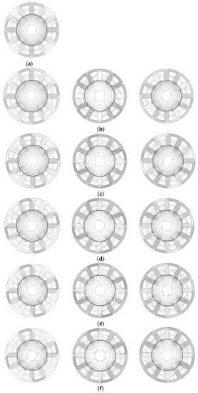
Figure 7.
Equal potential distributions for 12s8p-CCPPM. (from left to right: PM only, armature current only, overall) (a) 0A. (b) 10A (c) 20A. (d) 30A. (e) 40A. (f) 50A.
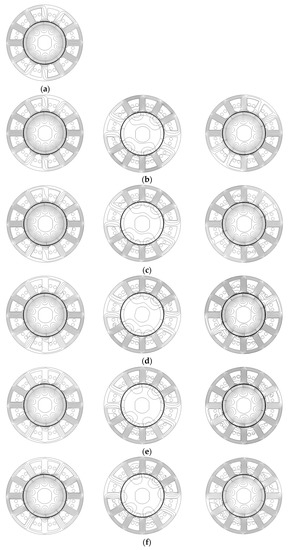
Figure 8.
Equal potential distributions for 12s10p-SPM. (from left to right: PM only, armature current only, overall) (a) 0A. (b) 10A (c) 20A. (d) 30A. (e) 40A. (f) 50A.
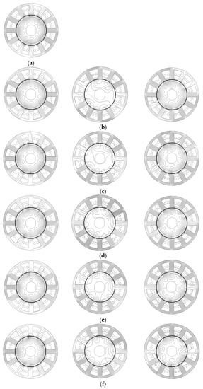
Figure 9.
Equal potential distributions for 12s10p-CCPPM. (from left to right: PM only, armature current only, overall) (a) 0A. (b) 10A (c) 20A. (d) 30A. (e) 40A. (f) 50A.
3.2. PM Flux-Linkage and Back EMF Characteristics
Figure 10 and Figure 11 show the amplitude variation of fundamental components (fundamental torque production harmonics) in phase A under different currents. Obviously, armature reaction has a negative influence on the amplitudes of PM flux-linkage and corresponding back-EMF for both SPM and CCPPM machines. Besides, the effects in the CPPM machines are more significant as proved by the larger variation range in both PM flux linkages and back EMFs. Figure 12, Figure 13, Figure 14 and Figure 15 show the d-/q-axis flux linkages and back-EMFs. It is clear that as the current rises, the amplitudes of harmonics are prone to increase, which can result in larger PM torque ripples. It can also be seen that the q-axis PM flux linkages and back-EMFs increase with the current increase, which means that the phase angles of PM fluxes can be shifted by the saturation produced by the armature reaction.

Figure 10.
Amplitudes of fundamental harmonics in phase-A for 12s8p machines.
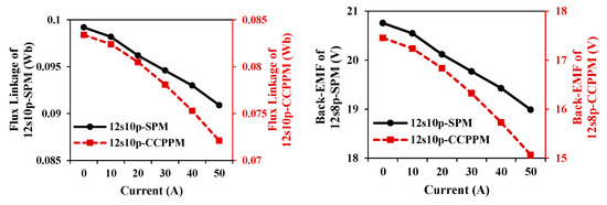
Figure 11.
Amplitudes of fundamental harmonics in phase-A for 12s10p machines.
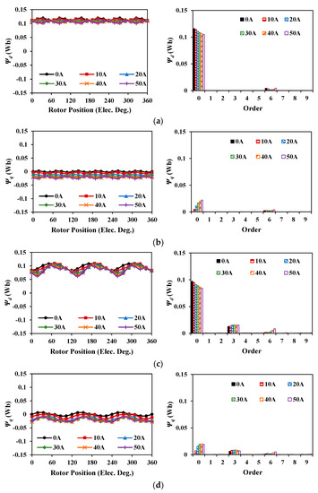
Figure 12.
Flux linkages and spectra for 12s8p machines. (a) D-axis flux linkage of 12s8p-SPM. (b) Q-axis flux linkage of 12s8p-SPM. (c) D-axis flux linkage of 12s8p-CCPPM. (d) Q-axis flux linkage of 12s8p-CCPPM.
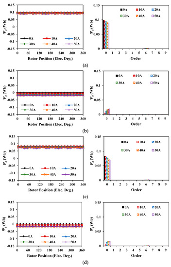
Figure 13.
Flux linkages and spectra for 12s10p machines. (a) D-axis flux linkage of 12s10p-SPM. (b) Q-axis flux linkage of 12s10p-SPM. (c) D-axis flux linkage of 12s10p-CCPPM. (d) Q-axis flux linkage of 12s10p-CCPPM.
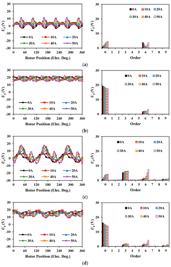
Figure 14.
Back-EMFs and spectra for 12s8p machines. (a) D-axis back-EMF of 12s8p-SPM. (b) Q-axis back-EMF of 12s8p-SPM. (c) D-axis back-EMF of 12s8p-CCPPM. (d) Q-axis back-EMF of 12s8p-CCPPM.
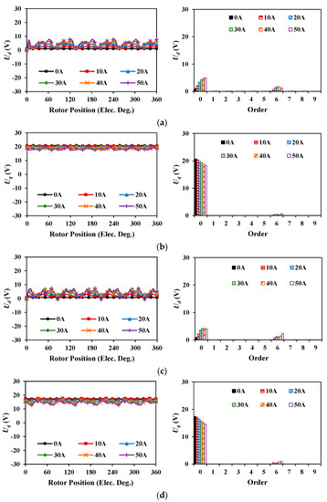
Figure 15.
Back-EMFs and spectra for 12s10p machines. (a) D-axis back-EMF of 12s10p-SPM. (b) Q-axis back-EMF of 12s10p-SPM. (c) D-axis back-EMF of 12s10p-CCPPM. (d) Q-axis back-EMF of 12s10p-CCPPM.
Since the north and south poles are unbalanced for CPPM machines, there will exist even order harmonics in air-gap flux densities and thus in flux linkages and back EMFs [11,12]. These even order harmonics in ABC-axes will be converted to the harmonics with multiples of three in d-/q-axis. As a dominant harmonic in d-/q-axis, the 3rd order harmonic will be emphasized in this paper. It should be noted that there exist 3rd order harmonics in 12s8p-CCPPM machine, while there are no 3rd order harmonics in 12s8p-SPM machine. However, there are no 3rd order harmonics in both 12s10p-CCPPM and 12s10p-SPM machines, which is due to the compensation effect of winding connection in 12s10p-CCPPM.
3.3. Inductance Characteristics
Figure 16, Figure 17, Figure 18 and Figure 19 show the inductance characteristics for 12s8p and 12s10p machines. Obviously, with the increase of current, the average values for all of these four machines decrease and for each machine, Lq has a larger variation range than Ld since the armature reaction mainly acts on the q-axis. Since the unbalanced features between north and south poles can be linked to windings for 12s8p-CCPPM machine, there exist harmonics in multiples of three. On the contrary, the 12s10p-CCPPM can overcome the unbalanced feature in CPPM rotor and it has the same harmonic contents as the 12s10p-SPM machine.
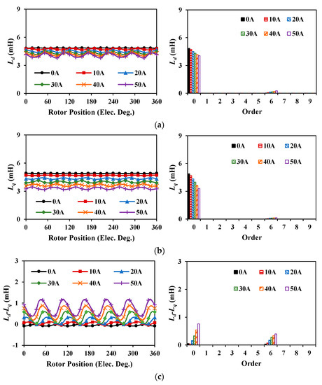
Figure 16.
Inductances and spectra for 12s8p SPM machine. (a) Ld. (b) Lq. (c) Ld-Lq.
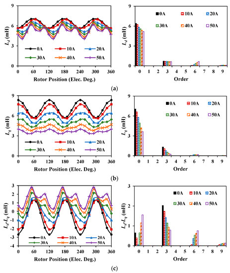
Figure 17.
Inductances and spectra for 12s8p CCPPM machine. (a) Ld. (b) Lq. (c) Ld-Lq.
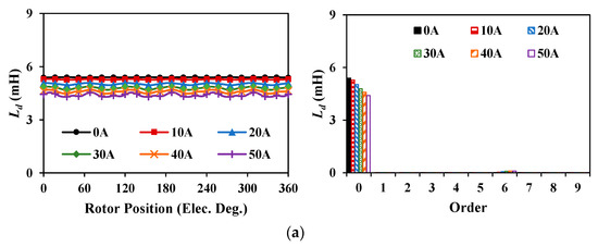
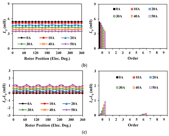
Figure 18.
Inductances and spectra for 12s10p SPM machine. (a) Ld. (b) Lq. (c) Ld-Lq.
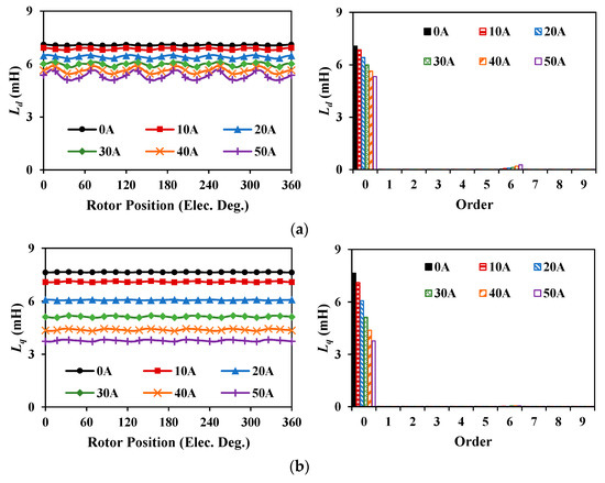
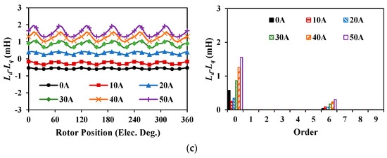
Figure 19.
Inductances and spectra for 12s10p CCPPM machine. (a) Ld. (b) Lq. (c) Ld-Lq.
Commonly, a higher armature reaction tends to result in higher pulsation in inductance, which can be seen in the amplitudes of 6th order harmonics in Ld and Lq for all the machines. However, the dominant 3rd order harmonics for 12s8p-CCPPM machine are smaller with the current increase, which leads to its decreasing trend of the overall fluctuation in inductance waveforms. This is because the saturation in iron pole can reduce the unbalance permeability between PM and iron poles in the rotor, which is the source of the dominant third-order harmonics in Ld and Lq [12]. Consequently, the overall fluctuation in differences between Ld and Lq for 12s8p-CCPPM machine shows a decreasing trend while an increasing trend can be seen in other machines. However, the reluctance torque is proportional to the square of the current. Therefore, the overall reluctance torque ripple still shows a rising trend with the current increase.
3.4. Torque Characteristics
Supposing the torque ripple Tripple is the ratio of peak to peak value to average value, the average torque and torque ripples are shown in Figure 20. Clearly, the differences between the average torques of SPM machines and those of CCPPM machines become larger with the increase of current, which indicates that CCPPM machines suffer from higher armature reactions and thus higher saturation levels. Figure 21 shows the torque ripple spectra for these machines. It can be found that only 12s8p-CCPPM has the 3rd order torque ripple and the dominant 3rd order torque ripple increases significantly as the current rises.
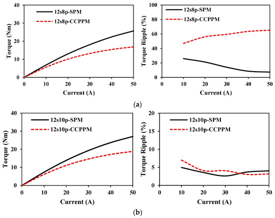
Figure 20.
Average torques and torque ripples for SPM and CCPPM machines. (a) 12s8p machines. (b) 12s10p machines.
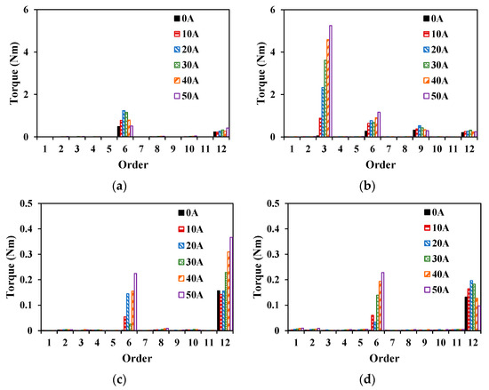
Figure 21.
Torque ripple spectra for SPM and CCPPM machines. (a) 12s8p-SPM. (b) 12s8p-CCPPM. (c) 12s10p-SPM. (d) 12s10p-CCPPM.
To analyze the torque ripple, Figure 22 shows the peak to peak values of torque components under different current conditions. Generally, all of the PM torque ripples, reluctance torque ripples, and cogging torque ripples increase as the current rises for all the machines. The unevenly distributed local saturation leads to fluctuating growth. Besides, the phase differences between torque ripple components result in the uneven growth of peak to peak value of overall torque. Considering the increased average torque, Tripple for different machines have different trends as shown in Figure 20.
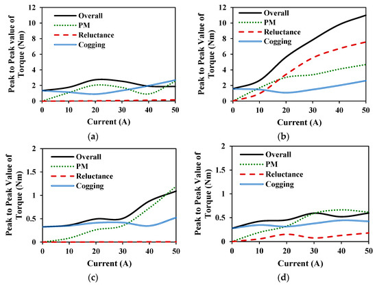
Figure 22.
Peak to peak values of torque ripples for SPM and CCPPM machines. (a) 12s8p-SPM. (b) 12s8p-CCPPM. (c) 12s10p-SPM. (d) 12s10p-CCPPM.
3.5. Demagnetization Analysis
Due to the larger armature reaction for CPPM machines, the demagnetization withstand capabilities of CPPM machines are weaker than those of SPM counterparts. To analyze the demagnetization withstand performances under the worst scenario, the temperatures of magnets are set as 80 °C in this part with the B-H curve presented in Figure 23. In the normal B-H curve, 0.3T is set as the knee point, which means that the areas can be treated as demagnetized when their flux density is below 0.3T. In addition, it is worth noting that the negative d-axis current is injected in this part.
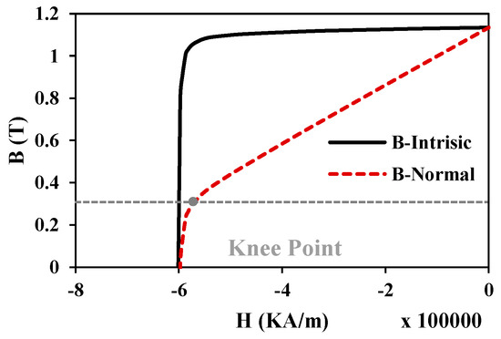
Figure 23.
B-H curve for N35 under 80 °C.
Supposing the demagnetization area ratio is defined as the demagnetized PM area to the whole PM area, the magnetic fields along the magnetization direction, namely the radial direction, in PMs for four machines are analyzed as the results shown in Figure 24 and Figure 25. It can be seen that under light load conditions, the demagnetization area ratios for both SPM and CCPPM machines are 0. However, when the current is larger, the demagnetization area ratios for CCPPM machines increase significantly while those for SPM machines still maintain a low level. This indicates that the CCPPM machines suffer from weaker demagnetization withstand capabilities.
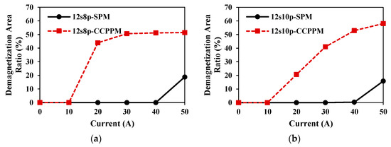
Figure 24.
Demagnetization area ratios with negative D-axis current. (a) 12s8p machines. (b) 12s10p machines.
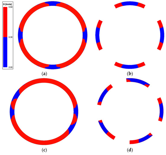
Figure 25.
Demagnetization area distribution in magnets under Id=−50A. (a) 12s8p-SPM. (b) 12s8p-CCPPM. (c) 12s10p-SPM. (d) 12s10p-CCPPM.
3.6. Section Summary
In this section, the influences of armature reaction of SPM and CPPM machines on various performances are analyzed and compared. Compared with SPM machines, the CPPM machines suffer from larger armature reaction, thus leading to a more serious drop of flux linkage and back EMF with the increased current. In addition, CPPM machines have lower average torque under heavy load conditions and higher demagnetization area.
4. Influence of Armature Reaction on Pole Shaping Effect for CPPM Machines
4.1. Magnetic Flux Density Characteristics
In this section, the asymmetric pole-shaped 12s8p CPPM machine and the symmetrical pole-shaped 12s10p CPPM machine are analyzed. As shown in Figure 26, the flux density waveforms distort with a higher current injected although it is not so obvious. However, as for the spectra, it is obvious that the amplitudes of fundamental harmonics drop with the increase of current, while the amplitudes of harmonics show different trends, which are caused by various local saturation conditions under different currents. Besides, the equal potential distributions are demonstrated in Figure 27 and Figure 28. Similar to CCPPM machines, PM fluxes and armature current fluxes will be shifted as the current increases.
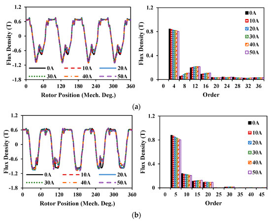
Figure 26.
Flux densities and spectra of two PSCPPM machines. (a) 12s8p-PSCPPM. (b) 12s10p-PSCPPM.
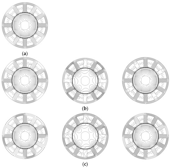
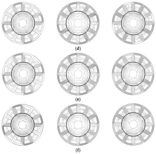
Figure 27.
Equal potential distributions for 12s8p-PSCPPM. (from left to right: PM only, armature current only, overall) (a) 0A. (b) 10A (c) 20A. (d) 30A. (e) 40A. (f) 50A.
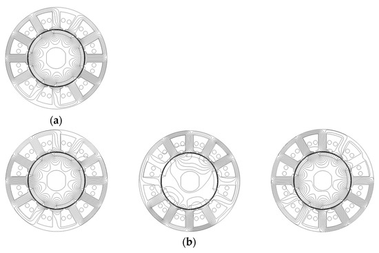
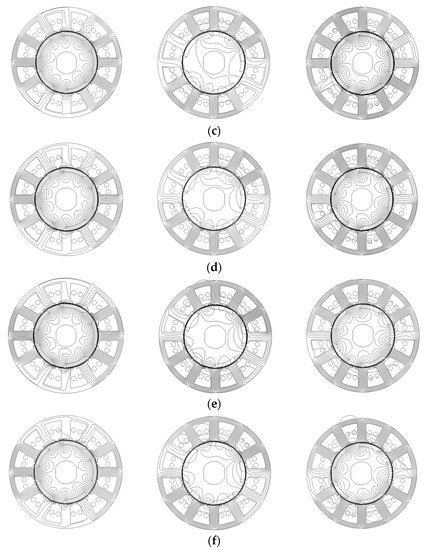
Figure 28.
Equal potential distributions for 12s10p-PSCPPM. (from left to right: PM only, armature current only, overall) (a) 0A. (b) 10A (c) 20A. (d) 30A. (e) 40A. (f) 50A.
4.2. PM Flux-Linkage and Back EMF Characteristics
Figure 29 and Figure 30 present the flux linkages and back EMFs for two PSCPPM machines, respectively. Obviously, a larger injected current can lead to larger deformation in flux linkage and back EMF waveforms, which means higher harmonic amplitudes, especially for the ψq and Ud. This is mainly because the q-axis part in iron has relatively low flux and it is easier to be affected by the saturation due to the steeper slope in B-H curve. The same as SPM and CCPPM machines, the drop and rise trends of amplitudes in d-/q- axis average values indicate the phase shift of magnet flux due to the armature reaction.
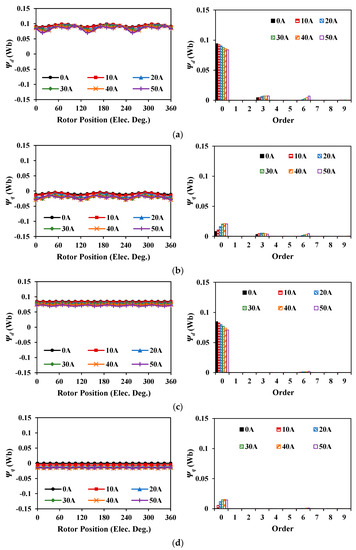
Figure 29.
Flux linkages and spectra of two PSCPPM machines. (a) D-axis flux linkage of 12s8p-PSCPPM. (b) Q-axis flux linkage of 12s8p-PSCPPM. (c) D-axis flux linkage of 12s10p-PSCPPM. (d) Q-axis flux linkage of 12s10p-PSCPPM.
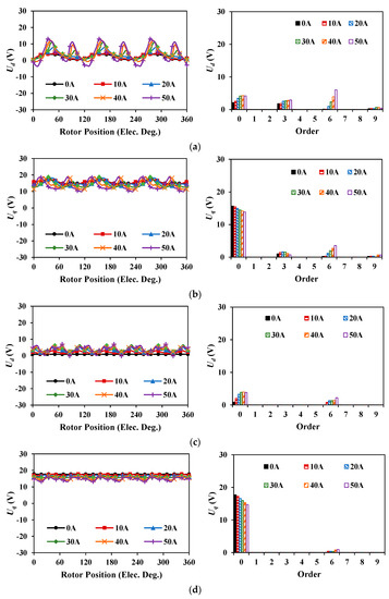
Figure 30.
Back EMFs and spectra of two PSCPPM machines. (a) D-axis back-EMF of 12s8p-PSCPPM. (b) Q-axis back-EMF of 12s8p-PSCPPM. (c) D-axis back-EMF of 12s10p-PSCPPM. (d) Q-axis back-EMF of 12s10p-PSCPPM.
4.3. Inductance Characteristics
Similar to CCPPM machines, the increase in current will result in drops in average and 3rd order harmonic amplitudes, while increases in the 6th order harmonic amplitudes as illustrated in Figure 31 and Figure 32. Such harmonics will lead to different characteristics in reluctance torque ripples for these machines.
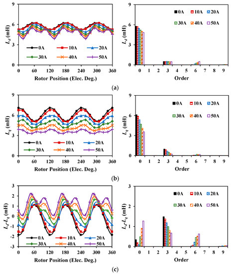
Figure 31.
Inductances and spectra of 12s8p-PSCPPM machine. (a) Ld. (b) Lq. (c) Ld-Lq.
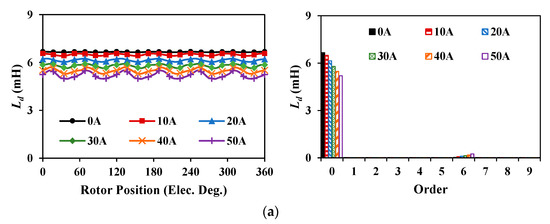
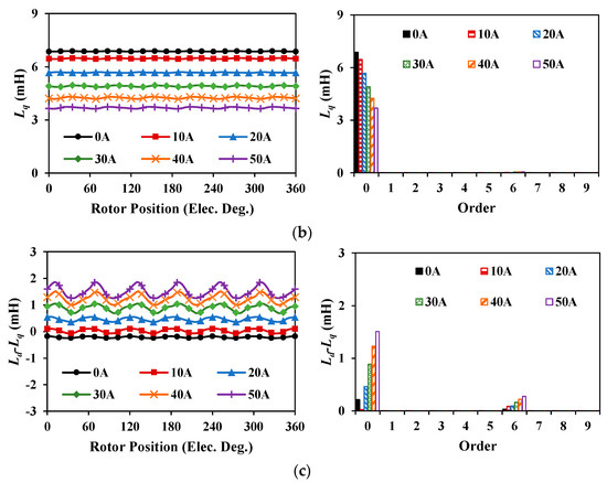
Figure 32.
Inductances and spectra of 12s10p-PSCPPM machine. (a) Ld. (b) Lq. (c) Ld-Lq.
4.4. Torque Characteristics
For the 12s8p-PSCPPM machine, ideally, reluctance torque is proportional to the square of the current, while PM torque is proportional to the current, as can be seen in Figure 33b with current under 20A. When the current is higher than 20A, saturation will suppress the improvement of both reluctance and PM torques. Since the 12s8p-PSCPPM machine is optimized under rated condition (10A) and torque ripple components can counteract each other at this condition, the different variations of amplitudes and phase angle for PM, reluctance, and cogging torques will inevitably lead to the fact that the torque ripple components cannot be completely canceled. Therefore, when the current is higher than 10A, the torque ripple increases significantly, Figure 33.
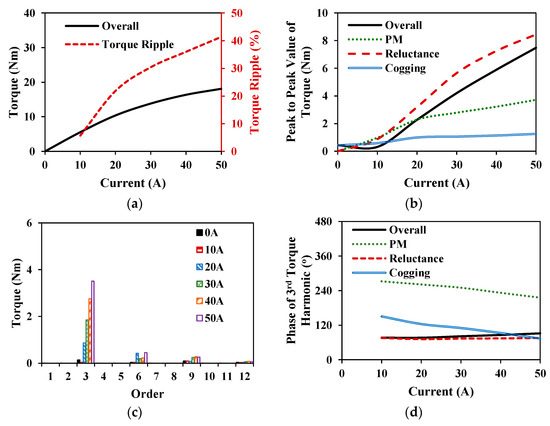
Figure 33.
Torque characteristics of 12s8p-PSCPPM machine. (a) Average torque and torque ripple. (b) Peak to peak value of torque components. (c) Overall torque ripple spectra. (d) Phases of dominant 3rd order torque harmonics.
However, for the 12s10p-PSCPPM machine, the unbalance of CPPM rotor can be eliminated and the performance is quite similar to the 12s10p-SPM counterpart. Therefore, the reluctance torque ripple is small and does not need to be considered under light load conditions. But under heavy load conditions, the reluctance torque increased slightly as shown in Figure 34b, which origins from the saturation caused by the armature reaction. Overall, as shown in Figure 34, the variations of peak to peak values for torques are much smaller and the torque ripple Tripple is relatively stable with the current increase.
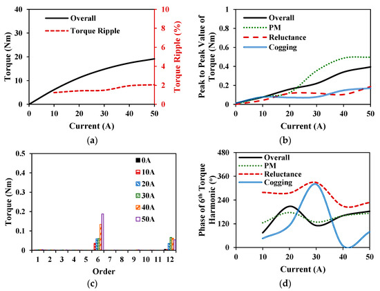
Figure 34.
Torque characteristics of 12s10p-PSCPPM machine. (a) Average torque and torque ripple. (b) Peak to peak value of torque components. (c) Overall torque ripple spectra. (d) Phases of dominant 6th order torque harmonics.
Generally, the higher current will cause the increase of all the torque ripple components, including PM torque, reluctance torque, and cogging torque, which in turn contribute to the increase of overall torque ripple, namely the quality of mechanical energy is degraded.
4.5. Demagnetization Analysis
With 80 °C and negative d-axis current, the demagnetization performances for two PSCPPM machines are demonstrated in Figure 35 where the magnetic fields along the magnetization direction in PMs are analyzed. As shown in Figure 36, it is evident that for two PSCPPM machines, the demagnetization areas are quite large even with a large equivalent airgap length, which means the weaker demagnetization withstand capabilities, compared with the SPM counterparts shown in Figure 25.
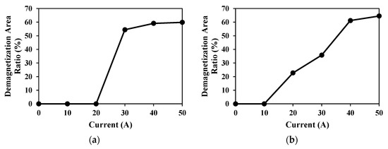
Figure 35.
Demagnetization area ratios negative d-axis current. (a) 12s8p-PSCPPM. (b) 12s10p-PSCPPM.
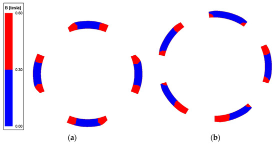
Figure 36.
Demagnetization area distribution under Id=−50A. (a) 12s8p-PSCPPM. (b) 12s10p-PSCPPM.
4.6. Section Summary
In this section, the influences of armature reaction of PSCPPM machines are analyzed. It can be found that the overall variation trend is similar to that of CCPPM machines, including flux linkage, back EMF, inductance, and demagnetization. However, as for the torque ripple reduction capability, the 12s8p-PSCPPM can only minimize the torque ripple under rated working condition while the torque ripple of 12s10p-PSCPPM machine is relatively stable with the current increase.
5. Experimental Results
To validate the FEM analysis results, four prototypes, namely 12s8p-CCPPM, 12s8p-PSCPPM, 12s10p-CCPPM, and 12s10p-PSCPPM, are manufactured and tested, Figure 37. The experiment test rigs are demonstrated in Figure 38 where the dynamic platform is used for testing on-load torques and back EMFs, while the static platform is used for testing cogging torques and inductances.
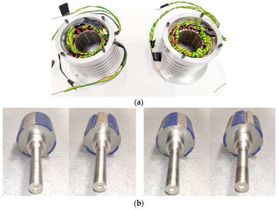
Figure 37.
Manufactured prototypes. (a) 12s8p (left) and 12s10p (right) stators. (b) Rotors (from left to right: 12s8p-CCPPM, 12s8p-PSCPPM, 12s10p-CCPPM, 12s10p-PSCPPM).
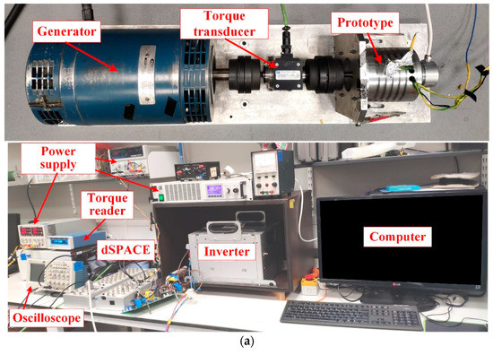
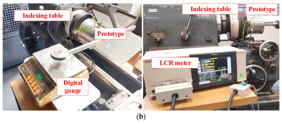
Figure 38.
Test rigs. (a) Dynamic platform. (b) Static platform.
5.1. Test with Static Platform
The method proposed in [19] is employed to test the cogging torques. Figure 39, Figure 40, Figure 41 and Figure 42 compare the experimental and FEM results under open circuit condition. In Figure 40 and Figure 42, it can be seen that the predicted inductances are always a little bit higher than that for tested results. This is largely a consequence of the fact that the end flux leakages are neglected in 2-D FEM. In fact, the flux leakage caused by the end effect will increase the flux reluctance and thus leading to lower inductance. In addition, since the prototype is handmade and the test rig will cause noise in the transient torque, there are small errors in cogging torques and inductances but the waveform shape is consistent. Overall, the experimental results agree well with FEM results, which validates the effectiveness of FEM results.
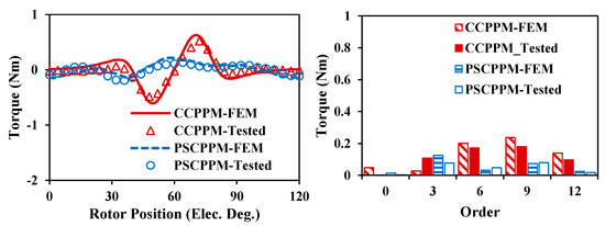
Figure 39.
Cogging torque waveforms and spectra of 12s8p machines.
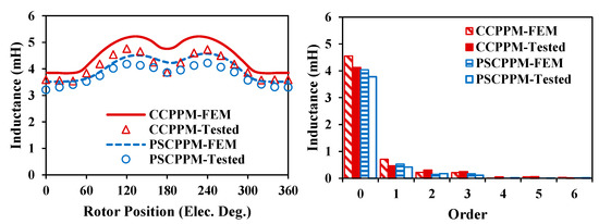
Figure 40.
Inductance waveforms and spectra of 12s8p machines.
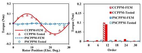
Figure 41.
Cogging torque waveforms and spectra of 12s10p machines.
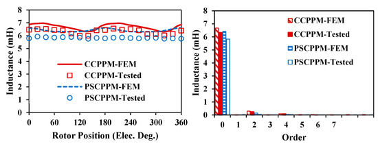
Figure 42.
Inductance waveforms and spectra of 12s10p machines.
5.2. Test with Dynamic Platform
With torque transducer and reader in the dynamic platform, the on-load torque waveforms for these four machines can be obtained as demonstrated in Figure 43 and Figure 44. It can be found that the tested torque ripples for two PSCPPM machines are a little larger than the FEM results, which is mainly due to assembly deficiencies and measurement errors etc., but the trend is in good agreement with the FEM results.
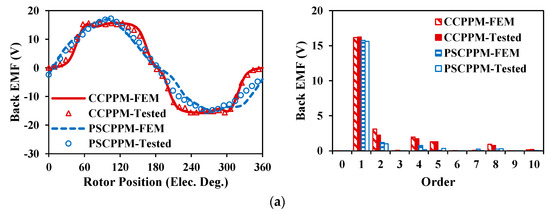
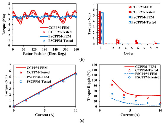
Figure 43.
On load performances of 12s8p machines. (a) Back EMFs. (b) Rated torques (10A). (c) Torque performances under different current.
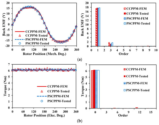
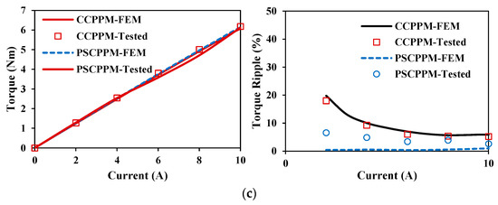
Figure 44.
On load performances of 12s10p machines. (a) Back EMFs. (b) Rated torques (10A). (c) Torque performances under different current.
Limited by the controller and the test rig, the prototype machines can only work with a maximum current of 10A. Consequently, Figure 43c and Figure 44c only show the torque performances under 10A. Obviously, with these conditions, the saturation caused by armature reaction is not serious thus leading to almost linear torque-current relationships. Although the high saturation conditions of prototypes cannot be tested, good agreement between experimental and FEM results in this section can be witnessed, which confirms that the FEA results can predict the performances accurately. Therefore, the overload performances predicted by FEA in Section 3 and Section 4 are credible and are indirectly verified by the experiments.
6. Conclusions
Focusing on the electromagnetic and mechanical energy conversion process, this paper investigates the influence of armature reaction in CPPM machines. Six machines with 12s8p and 12s10p are selected to demonstrate the influence of armature reaction. Firstly, SPM and CCPPM machines are compared to show the general influence of armature reaction on CPPM machines. It is found that the amplitudes of the 3rd order inductance harmonics reduce in 12s8p-CCPPM machine with the increase of current, but the overall torque ripples still show an increasing trend. Then, the influences of armature reaction on pole-shaped machines are analyzed, which shows that the 12s8p-PSCPPM machine can only achieve low torque ripple, namely high-quality mechanical energy, in a small range around the rated working condition, while the 12s10p-PSCPPM machine can achieve much lower torque ripple in a wide range. In addition, it is also found that CPPM machines suffer from weaker demagnetization withstand capabilities and weaker overload capabilities than SPM counterparts due to the large armature reactions. The FEM results are validated by experimental results with four prototypes.
Author Contributions
Conceptualization, J.Q. and Z.Z.; methodology, J.Q. and Z.Z.; validation, J.Q. and L.Y.; formal analysis, J.Q., Z.Z. and L.Y.; investigation, J.Q., Z.Z. and L.Y.; resources, Z.Z., G.W.J., S.B. and C.H.; data curation, J.Q.; writing—original draft preparation, J.Q.; writing—review and editing, Z.Z.; supervision, Z.Z., G.W.J., C.G., Y.R., S.B. and C.H.; project administration, Z.Z., G.W.J., C.G., Y.R., S.B. and C.H.; funding acquisition, Z.Z., G.W.J., S.B. and C.H. All authors have read and agreed to the published version of the manuscript.
Funding
This research was funded by UK EPSRC Future Electrical Machines Manufacturing Hub (EP/S018034/1) and Protean Electric Ltd.(X/154584-11-1).
Data Availability Statement
Not applicable.
Conflicts of Interest
The authors declare no conflict of interest.
References
- Chung, S.U.; Kim, J.W.; Chun, Y.D.; Woo, B.C.; Hong, D.K. Fractional slot concentrated winding PMSM with consequent-pole rotor for a low-speed direct drive: Reduction of rare earth permanent magnet. IEEE Trans. Energy Convers. 2015, 30, 103–109. [Google Scholar] [CrossRef]
- Li, J.; Wang, K. Analytical determination of optimal PM-arc ratio of consequent-pole permanent magnet machines. IEEE/ASME Trans. Mechatron. 2018, 23, 2168–2177. [Google Scholar] [CrossRef]
- Wu, L.; Qu, R. Comparison of conventional and consequent pole interior permanent magnet machines for electric vehicle application. In Proceedings of the 2014 17th International Conference on Electrical Machines and Systems (ICEMS), Hangzhou, China, 22–25 October 2014. [Google Scholar]
- Hu, Y.; Xiao, Y.; Chen, B.; Li, Q. Topology optimization of a consequent-pole rotor with V-shaped magnet placement. In Proceedings of the 2018 21st International Conference on Electrical Machines and Systems (ICEMS), Jeju, Republic of Korea, 7–10 October 2018. [Google Scholar]
- Boroujeni, S.T.; Emami, S.P.; Takorabet, N.; Mahmoudi, A. Analytical investigation of the armature current influence on the torque and radial force in eccentric consequent-pole PM machines. IET Electr. Power Appl. 2021, 15, 1751–8660. [Google Scholar]
- Zhu, M.; Wu, L.; Fang, Y.; Lubin, T. Subdomain model for predicting armature reaction field of dual-stator consequent-pole PM machines accounting for tooth-tips. CES Trans. on Electr. Mach. Syst. 2019, 3, 143–150. [Google Scholar] [CrossRef]
- Chung, S.; Moon, S.; Kim, D.; Kim, J. Development of a 20-pole–24-slot SPMSM with consequent pole rotor for in-wheel direct drive. IEEE Trans. Ind. Electron. 2016, 63, 302–309. [Google Scholar] [CrossRef]
- Dhulipati, H.; Mukundan, S.; Li, Z.; Ghosh, E.; Tjong, J.; Kar, N.C. Torque performance enhancement in consequent pole PMSM based on magnet pole shape optimization for direct-drive EV. IEEE Trans. Magn. 2021, 57, 1–7. [Google Scholar] [CrossRef]
- Watahiki, T.; Toriumi, Y.; Miki, I. A consequent pole motor with novel pole structure. In Proceedings of the 2018 International Symposium on Power Electronics, Electrical Drives, Automation and Motion (SPEEDAM), Amalfi, Italy, 20–22 June 2018. [Google Scholar]
- Zhang, G.; Wang, K.; Li, J.; Zheng, R.; Kong, J. Torque ripple reduction of consequent-pole permanent magnet machine by shaped rotor. In Proceedings of the 2020 IEEE 9th International Power Electronics and Motion Control Conference (IPEMC2020-ECCE Asia), Nanjing, China, 29 November 2020–2 December 2020. [Google Scholar]
- Qi, J.; Zhu, Z.Q.; Yan, L.; Jewell, G.W.; Gan, C.W.; Ren, Y.; Brockway, S.; Hilton, C. Effect of pole shaping on torque characteristics of consequent pole PM machines. IEEE Trans. Ind. Appl. 2022, 58, 3511–3521. [Google Scholar] [CrossRef]
- Qi, J.; Zhu, Z.Q.; Yan, L.; Jewell, G.W.; Gan, C.W.; Ren, Y.; Brockway, S.; Hilton, C. Suppression of torque ripple for consequent pole PM machine by asymmetric pole shaping method. IEEE Trans. Ind. Appl. 2022, 58, 3545–3557. [Google Scholar] [CrossRef]
- Qi, J.; Zhu, Z.Q.; Yan, L.; Jewell, G.W.; Gan, C.W.; Ren, Y.; Brockway, S.; Hilton, C. Analytical analysis of cogging torque in permanent magnet machines with unequal north and south poles, with particular reference to consequent pole machines. IEEE Trans. Energy Convers. 2022; (Early Access). [Google Scholar]
- Liu, Y.; Zhu, Z.Q.; Howe, D. Direct torque control of brushless DC drives with reduced torque ripple. IEEE Trans. Ind. Appl. 2005, 41, 599–608. [Google Scholar] [CrossRef]
- Chung, S.; Kim, H.; Kim, C.; Youn, M. A new instantaneous torque control of PM synchronous motor for high-performance direct-drive applications. IEEE Trans. Power Electron. 1998, 13, 388–400. [Google Scholar] [CrossRef]
- Yan, L.C.; Liao, Y.; Lin, H.; Sun, J. Torque ripple suppression of permanent magnet synchronous machines by minimal harmonic current injection. IET Power Electron. 2019, 12, 1368–1375. [Google Scholar] [CrossRef]
- Azar, Z.; Zhu, Z.Q.; Ombach, G. Influence of electric loading and magnetic saturation on cogging torque, back-EMF, and torque ripple of PM machines. IEEE Trans. Magn. 2012, 48, 2650–2658. [Google Scholar] [CrossRef]
- Chen, X.; Wang, J.; Patel, V.I.; Lazari, P.; Chen, L.; Lombard, P. Reluctance torque evaluation for interior permanent magnet machines using frozen permeability. In Proceedings of the 7th IET International Conference on Power Electronics, Machines and Drives (PEMD), Manchester, UK, 8–10 April 2014. [Google Scholar]
- Zhu, Z.Q. A simple method for measuring cogging torque in permanent magnet machines. In Proceedings of the 2009 IEEE Power & Energy Society General Meeting, Calgary, AB, Canada, 26–30 July 2009. [Google Scholar]
Disclaimer/Publisher’s Note: The statements, opinions and data contained in all publications are solely those of the individual author(s) and contributor(s) and not of MDPI and/or the editor(s). MDPI and/or the editor(s) disclaim responsibility for any injury to people or property resulting from any ideas, methods, instructions or products referred to in the content. |
© 2023 by the authors. Licensee MDPI, Basel, Switzerland. This article is an open access article distributed under the terms and conditions of the Creative Commons Attribution (CC BY) license (https://creativecommons.org/licenses/by/4.0/).