Article

Experimental Investigation of Impacts of Initial Pressure Levels on Compression Efficiency and Dissolution in Liquid Piston Gas Compression

Department of Mechanical Engineering, Baylor University, Waco, TX 76798, USA
*
Author to whom correspondence should be addressed.
Energies 2023, 16(4), 1921; https://doi.org/10.3390/en16041921
Submission received: 20 January 2023 / Revised: 9 February 2023 / Accepted: 12 February 2023 / Published: 15 February 2023

Abstract

:
Understanding how the pressure level affects the efficiency of liquid piston gas compression is essential for a greater applicability of the technology in compressed air energy storage. To explore the impacts, compression starting at three different initial pressure levels (1, 2, 3 bar) with a pressure ratio of 2 is performed, and how isothermal compression efficiencies are affected depending on the initial pressures is analyzed. Under the experimental conditions, higher initial pressure leads to lower isothermal efficiency. Air dissolution during the compression is also investigated because the chamber is a pressure-varying and a liquid-containing environment, where the gas solubility changes during the process. Evaluating the dissolution is critical as it affects the energy output when the compressed air is expanded to regenerate the energy. The changes in the air mass and the retrievable volume of the air after expansion are quantified based on Henry’s law. For a compression at higher pressure, because the air solubility is proportional to pressure, a greater reduction in the air mass and volume percentages is expected. This trend of the mass decreasing with the pressure level leads to less energy output than the originally intended output when the stored energy is retrieved in a discharging process.

1. Introduction

Climate change is one of the most urgent issues that require much attention. For some developing countries that heavily depend on agriculture, it can bring about a heavier burden on their population [1]. Promoting the use of renewable energy sources can reduce fossil fuel use and curtail greenhouse gas emissions [2], which will lead to curbing climate change. However, their intermittent nature is a challenging issue when it comes to exploiting renewable energy, and building an energy storage system can help overcome the issue [3,4]. Storing energy when the demand for energy is low and distributing the stored energy to the population in on-peak hours enables a consistent supply of energy.
Compressed air energy storage (CAES) is one of the few bulk-scale energy storage options that are already commercialized. Due to the economic and environmentally friendly features of CAES, it is perceived as a promising choice for energy storage [5,6]. The fundamental mechanism of CAES is to store energy in the form of compressed air. During peak hours, the stored compressed air is expanded to run a turbine to restore the energy [7,8]. As a gas is compressed, heat is generated, whereas heat is lost when a gas expands. Depending on how CAES treats the heat generated during compression, it can be classified into three different types: diabatic CAES (D-CAES), adiabatic CAES (A-CAES), and isothermal CAES (I-CAES) [9,10]. In D-CAES, compression heat is dissipated before the compressed air is transferred to a storage vessel. In the discharging phase to regenerate the stored energy, an external energy source such as natural gas needs to be brought in to increase the temperature of the gas because gas expansion accompanies a significant temperature drop [9,11]. In D-CAES, the heat dissipation leads to the loss of energy. The idea of A-CAES stems from saving the heat energy that is wasted in conventional D-CAES. In A-CAES, a thermal energy storage device stores the compression heat energy generated during the compression step. In the discharging process, the stored heat can be employed to increase the gas temperature instead of using an external energy source. Therefore, it reduces the energy waste and eliminates the need for extra heat supply [9]. I-CAES is considered to be the most efficient among the three types [9,10]. By maximizing heat transfer, the temperature change is minimized during compression/expansion [12,13]. Because no energy is compromised by the heat generation, less work input is needed to compress air [12]. In addition, it does not require an extra device such as a thermal energy storage device of A-CAES, and no extra energy input is needed for the expansion stage. Owing to its promising characteristics, a variety of I-CAES models have been studied. Researchers in [14] proposed a system equipped with a near-isothermal compression system for wind energy, which serves as one of the major electricity generation sources in the US [15] and is rapidly growing globally [16]. According to their quantified evaluation, the suggested model resulted in the size and weight reduction, which leads to cost saving [14]. Researchers in [17] focused on the expansion process where the energy discharging takes place. Compared to adiabatic expansion, the introduction of their near-isothermal expander resulted in a 15.7% increase in specific work.
The liquid piston gas compression concept was recently re-introduced by Van de Ven and Li [12]. The fundamental mechanism of the compressor is that a liquid column functions as the piston of a conventional reciprocating compressor. It has been drawing attention as an innovative compression technique for energy storage applications as a variety of heat transfer improvement techniques can be utilized in the compressor, owing to the conforming nature of a liquid that can take a complicated shape. In other words, it has a great potential to achieve a near-isothermal process. A number of experimental and simulation studies have been performed to investigate the heat transfer improvement techniques in a liquid piston compressor. Placing an insert is a direct way to provide extra surface area for heat transfer. The effects of porous media and interrupted-plate-type inserts were examined in [18]. For the same level of power density in their test, a 18% efficiency increase was achieved with the inserts. According to [19], at the much higher target pressure of 210 bar, compression efficiency improvement was observed with the use of porous media. Metal wire mesh inserts were introduced as an insert for the liquid piston in [20]. An increase of 6–8% in compression efficiency with the metal wire inserts was attained over the baseline liquid piston compression. By testing two different materials, aluminum and copper, the impacts of the thermal property of an insert were also studied, and it turned out that the material does not make a notable efficiency change. Metal plates were also used as an insert in [21]. By varying the compression speed and the dimensions of inserts, a compression efficiency improvement of up to 8% was observed under their experimental conditions. Liquid-based heat transfer techniques have also been studied. Researchers in [13] investigated factors that affect droplet heat transfer by varying the mass of injected water and droplet size. To some degree, reducing the size of droplets is beneficial, and enlarging the mass of droplet injection is advantageous for boosting heat transfer. Researchers in [22] experimentally evaluated the spray injection technique by varying the angle of the nozzle and spray injection pressure. Higher injection pressure leads to higher flowrate and introduces a greater amount of water into the compression chamber. Thus, less temperature increase during compression was observed. However, as higher injection pressure requires higher work input, a higher spray pressure does not always guarantee a better overall efficiency despite the smaller temperature increment. Researchers in [23] examined the effectiveness of utilizing two proven techniques of metal inserts and spray injection at a time. They performed a more detailed analysis of the impacts of spray injection pressure on droplet heat transfer at different injection pressures. They proved that the spray pressure is critical in determining droplet heat transfer, including the size and velocity of a droplet as well as spray flowrate, all of which have an impact on droplet heat transfer and are dependent on the pressure. Aqueous foam is another liquid-based heat transfer technique, and an experimental investigation was carried out in [24]. Aqueous foam is generated inside the compression chamber so that extra heat transfer surface area is provided, and it increases the isothermal efficiency to 92% from 86% of the compression without the foam. Compared to the way spray injection is employed in [22,23], where the nozzle is continuously in operation throughout the compression, foam generation is carried out once before the compression begins. Therefore, it is expected to save work input compared to the other liquid-based method. A similar gas compression technique that utilizes a liquid and a porous medium was introduced and experimentally assessed in [25,26]. They examined the issue of gas dissolution during compression, which needs to be addressed when a liquid is used for compression. Using Henry’s law, the amount of dissolved air was estimated based upon a proportional relationship between the solubility and the pressure. A scaled-up liquid piston has also been tested in [27]. A chamber with a volume of 24.71 m 3 was designed, and exergy-based efficiency evaluation was performed under various experimental conditions. On top of bringing external heat transfer enhancement, a variety of approaches to optimizing the liquid piston itself have also been made. In [28], chambers designed with diverse design parameters were examined. Because the shape of the chamber affects the flow behavior of the internal air, the change in the chamber shape can result in heat transfer efficiency variations. In [29], compression speed was varied and different liquid piston chambers were experimentally investigated. The faster compression leads to lowered isothermal performance, and the thermal conductivity of the chamber material has a relatively small impact on heat transfer performance. A chamber that consists of a number of tube arrays was also tested [30]. Increasing the number of tubes leads to a positive effect on compression efficiency.
Many experimental studies on liquid piston compression focus on compression starting from atmospheric pressure or compression with a single case of pressure variation. In the current work, liquid piston gas compression at different initial pressure levels is tested, and how the different pressure affects compression efficiency for the same pressure ratio is examined. As multi-stage compression can lead to a better efficiency than single-stage compression [31], and the CAES plants in the actual operation employ multi-stage compressors [9,32,33], this work can aid in evaluating the real applicability of a liquid piston at an elevated pressure in a multi-stage system. Furthermore, this can pave the way for the future application of pressure-sensitive techniques such as spray injection and aqueous foam by broadening the fundamental understanding of liquid piston efficacy at various pressures. In addition, the dissolution issue of a liquid piston is also investigated by estimating how much air dissolution takes place for each process. It is also identified whether the difference in the dissolution contributes to the compression efficiency. There have been separate studies that examined the impact of the initial pressure [27,30] or identified the dissolution issue [25,26,34,35] in a liquid piston or similar liquid-based compression systems. To the author’s best knowledge, this is the first work that relates the impacts of different pressure levels on liquid piston compression efficiency and air dissolution. Because this work examines relatively moderate pressure ranges, which were not covered in [27,30] and where air solubility data can be easily estimated with the data available in [36], those two issues that are closely associated can be studied simultaneously. Another novelty of the current work is to investigate how the dissolution affects the overall efficiency of the energy storage system. In addition, by taking into consideration the discharging process of CAES, the study allows for a practical evaluation of a liquid piston system for energy storage applications.
This paper consists of five sections. The current section introduces the background of this research. The following section illustrates the analytical modeling to describe the concept and the methodology with the experimental apparatus description. The next section presents the results of the experiments. Then, analysis of the results is presented in the following section. Lastly, the paper ends with concluding remarks.

2. Materials and Methods

2.1. Analytical Modeling

The mathematical model of the liquid piston system used in this work can be represented in the same way as [20,22,23,24,29]. Using the first law of thermodynamics, the energy equation for liquid piston gas compression can be written as Equation (1).
U ˙ = Q ˙ W ˙ c o m p  
where U ˙ , Q ˙ , and W ˙ c o m p indicate the rate of internal energy, heat transfer, and compression work, respectively. Each term has an alternative form as follows:
U ˙ = m g a s C v d T g a s d t
Q ˙ = U h A s ( T T g a s )
W ˙ c o m p = P g a s d V g a s d t
By replacing the terms with the alternative forms, Equation (1) can be rewritten as Equation (5):
m g a s C v d T g a s d t = U h A s ( T T g a s ) P g a s d V g a s d t
From Equation (5), W ˙ c o m p is positive due to the volume decrease, and Q ˙ is negative because the gas temperature increases and becomes higher than the environmental temperature during compression. Hence, the right-hand side is equivalent to the difference in the absolute values of the work rate term and the heat transfer term. Equation (5) can be rearranged in terms of the gas temperature change.
d T g a s d t = | W ˙ c o m p | | Q ˙ | m g a s C v
Generally, in gas compression, | W ˙ c o m p | is greater than | Q ˙ | . By increasing heat transfer, the numerator of the right-hand side of Equation (6) becomes closer to zero. This results in a smaller temperature change rate on the left-hand side, bringing it closer to an isothermal compression with a reduced work input.
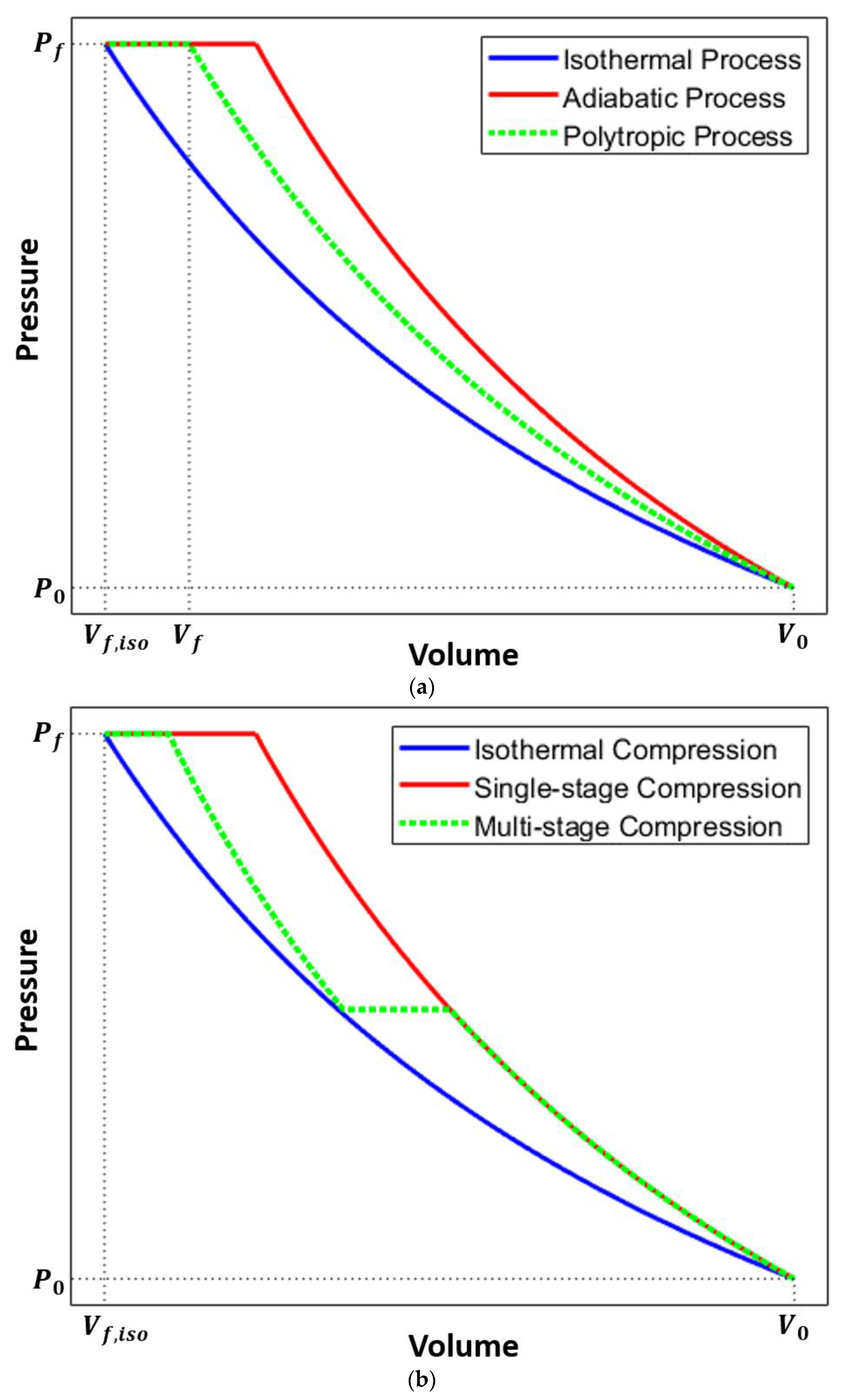
Figure 1 was motivated by [31] and displays the pressure–volume trajectories of various gas compression processes starting from the initial point of ( V 0 , P 0 ) to the compression end point of ( V f , i s o , P f ) . Figure 1a compares typical trajectories of isothermal, adiabatic, and polytropic compression processes. Equation (7) gives the polytropic process expression [37]:
P 1 V 1 n = P 2 V 2 n
For the isothermal process, the polytropic index n of Equation (7) is 1, while it is 1.4 for the adiabatic process [10]. If the index has a closer value to 1, the trajectory labeled as the Polytropic Process moves closer to the isothermal process trajectory. For a non-isothermal process, it attains the desired pressure P f at V f before the gas volume reaches the desired volume of V f , i s o . Thus, extra cooling work is needed to move from V f to V f , i s o [22,29,38]. The amount of work input can be determined by calculating the area under its trajectory. Thus, the isothermal process takes less work input to complete the compression compared to non-isothermal processes, and less energy is required to perform compression if the polytropic index is smaller and closer to the isothermal process, as shown in Figure 1a. The isothermal efficiency of a certain process can be obtained with Equation (8) where P r is the pressure ratio, P f / P 0 [29,38].
η i s o = W i s o t h e r m a l W a c t u a l = m R T 0 ( l n P r 1 + 1 P r ) W i s o t h e r m a l V 0 V f ( P ( V ) P 0 ) d V W c o m p + P 0 ( P r 1 ) ( V f V 0 P r ) W c o o l i n g 100   [ % ]
Figure 1b straightforwardly shows why multi-stage compression can be more efficient than single-stage compression. The two trajectories have the same polytropic index. However, by pausing in the middle of the process and allowing for cooling down, the multi-stage compression consumes less work input than the single-stage compression. Although an actual cooling process may not follow an ideal flat profile as it is shown in Figure 1b, it gives an idea on how multi-stage compression can be advantageous.
Gas dissolution needs to be identified because the liquid piston chamber is a pressure-varying environment that contains water. The dissolution affects multiple aspects of evaluating the liquid piston technique. It complicates the overall gas temperature estimation during the compression. Many experimental studies of the liquid piston employed a thermocouple to directly measure the temperature of the gas during the process [20,22,23,24,29,39]. However, because the measured temperature is local to the tip of the thermocouple, the overall temperature of the air inside the chamber cannot be represented with the measured value. The ideal gas equation can be used to calculate the overall temperature with the simple modification as Equation (9).
T = P V m R
Previous simulation-based liquid piston studies used the ideal gas equation to estimate the temperature of the next step by combining the polytropic process relationship of Equation (7) [12,13].
T i = T i 1 V i 1 n 1 V i n 1
However, if air dissolves and the mass of the air changes during the process, the temperature obtained based on the ideal gas equation leads to an error. This results in a circular problem in this study when it comes to estimating the gas temperature and the dissolved mass with the ideal gas equation. The mass of the air is needed to calculate the air temperature, while the mass calculation requires the air temperature. Hence, the quantification of the gas mass changes during compression is highly implausible with the ideal gas equation. However, the quantification of the dissolved gas is critical because it affects the compression work input and the energy that can be restored. Employing the proportional relationship of the gas solubility and pressure is a proper approach to estimating the dissolved gas. Henry’s law illustrates the proportional relationship of the gas dissolution [36].
S g a s = P g a s k H
Even with Henry’s law, it is still highly difficult to perform a real-time quantification of the dissolved gas because the basic form of Henry’s law equation has a single variable for pressure while temperature affects the solubility values as well. Therefore, it is difficult to make a proper adjustment to the equation for every data point. Hence, simplified estimations with solubility data available on [36] are made. The total reduced work from the dissolution can be calculated using the following equation, which calculates the area under the linear profile of the solubility and pressure.
W d i s = ( P f P 0 ) ( S f S 0 ) V w / 2
The dissolution is advantageous for the isothermal compression efficiency calculation with Equation (8), whereas the mass loss due to the dissolution during compression cannot be restored back outside the chamber and compromises the amount of energy that can be restored. To evaluate how much work is compromised when the energy is discharged, the mass loss from the dissolution needs to be calculated. Assuming the air follows the ideal gas law, the air mass loss from the dissolution is quantified by employing the solubility data and the ideal gas equation.

2.2. Experimental Apparatus

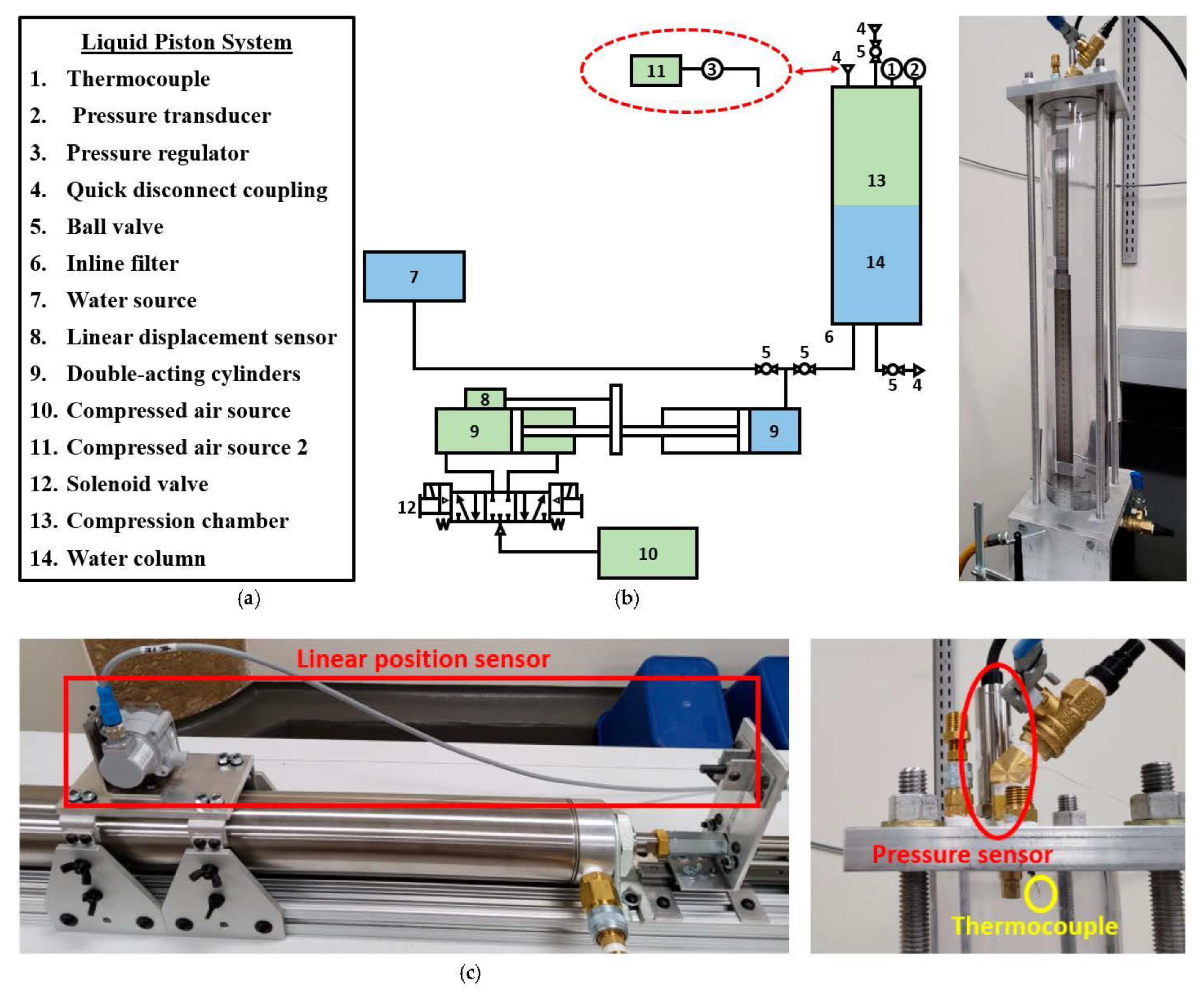
A liquid piston gas compressor setup was built for the current study. Figure 2 presents a schematic diagram of the system and the actual picture of the compression chamber.
The schematic diagram of the overall system configuration is depicted in Figure 2a. A 2-foot-long transparent polycarbonate cylinder sandwiched by two aluminum plates serves as a compression chamber (#14 in the diagram). The inner diameter is 3.5 inches and the outer diameter is 4 inches. The initial water level is set slightly above the bottom of the chamber so that the height of the gas-filled region is about 22.5 inches. Two pneumatic cylinders (#9) function as a water pump to convey water into the chamber. As one of the cylinders (#9 left) connected to a power source (#10) extends, the water residing in the other cylinder (#9 right) directly coupled with the chamber is pushed into the chamber. As the water enters the chamber and the water level increases, the air inside the chamber is compressed. To measure the volume of the gas, a position sensor (#8) is installed on the water pumping system. A thermocouple (#1), pressure transducer (#2), a quick-disconnect valve coupler (#4), and an on/off valve (#5) are placed on the cap of the chamber. The quick-disconnect coupler is located 1 inch away from the axial center of the top plate and is used to set or initialize the pressure of the gas. For experiments that require higher initial pressures, air is injected through the coupler and the gas pressure rises with the red-circled parts connected to another compressed air injection source (#11). When the pressure level needs to be initialized to the atmospheric pressure, a quick-disconnect plug is used to open the coupler, which works as an outlet to the atmosphere. On the ceiling of the chamber at the axial center, a spray nozzle is positioned for the integration of the droplet injection heat transfer technique, which is not used in this current study. Figure 2c shows the configuration of the sensors. The thermocouple and the pressure transducer are located 1 inch away from the axial center of the cap of the chamber and directly measure the temperature and pressure of air. The linear position sensor that measures the displacement of the rod end of the cylinders enables the measurement of air volume. By measuring the position, the amount of water entering the chamber can be calculated. The water volume entering the chamber means the change in the volume of air inside the chamber. As it is an indirect way to measure the volume and it may include some machining error during the installation, additional tests were carried out to compare the water volume changes calculated from the sensor and the changes in the liquid piston level. For the water level, an error of around or higher than 1% was observed in the early stage of the process. Near the end of the process, it was mostly less than 1%. The manufacturer, model name, and accuracy information of the sensors used in this study are summarized in Table 1.
To examine the impacts of the initial pressure levels on isothermal efficiency, air compression processes were performed for three different initial pressure levels of atmospheric pressure, which was about 1 bar, 2 bars, and 3 bars. The target pressure ratio was 2 for all the three pressure cases. Compression was carried out for a certain time until a pressure ratio higher than 2 was reached to be safe. Then, the profiles from the starting point to the pressure ratio of 2 were compared. By adjusting the water pump power for each case, the stroke times taken to reach the target ratio were closely matched. For the process at the atmospheric pressure, once the compression was finished, the outlet was manually opened to initialize the pressure level to the atmospheric pressure. Then, the liquid piston was retracted, resulting in water taken out of the chamber. For the compression starting from 2 and 3 bars, all the procedures were automated using an Arduino controller. The initial pressure was set-up by injecting air through the valve on the top plate (#4), and a pressure regulator adjusted the pressure to the desired level before performing compression. Due to the manual operation, the initial pressure levels were not exactly 2 and 3 bars. Once the compression was finished, the expansion was performed over a few steps to prevent the sudden temperature drop in a short time, which may not be desirable for the sensor operations. Throughout these processes with the elevated initial pressure, the outlet did not open to the outside and the system remained closed for the constant starting pressure levels. This process was repeated six times and the last five of them were averaged for comparison. Between strokes, a rest time was taken to wait for the system to become thermally stable and to set constant experimental conditions for each stroke.

3. Results

3.1. Compression Starting from Atmospheric Pressure

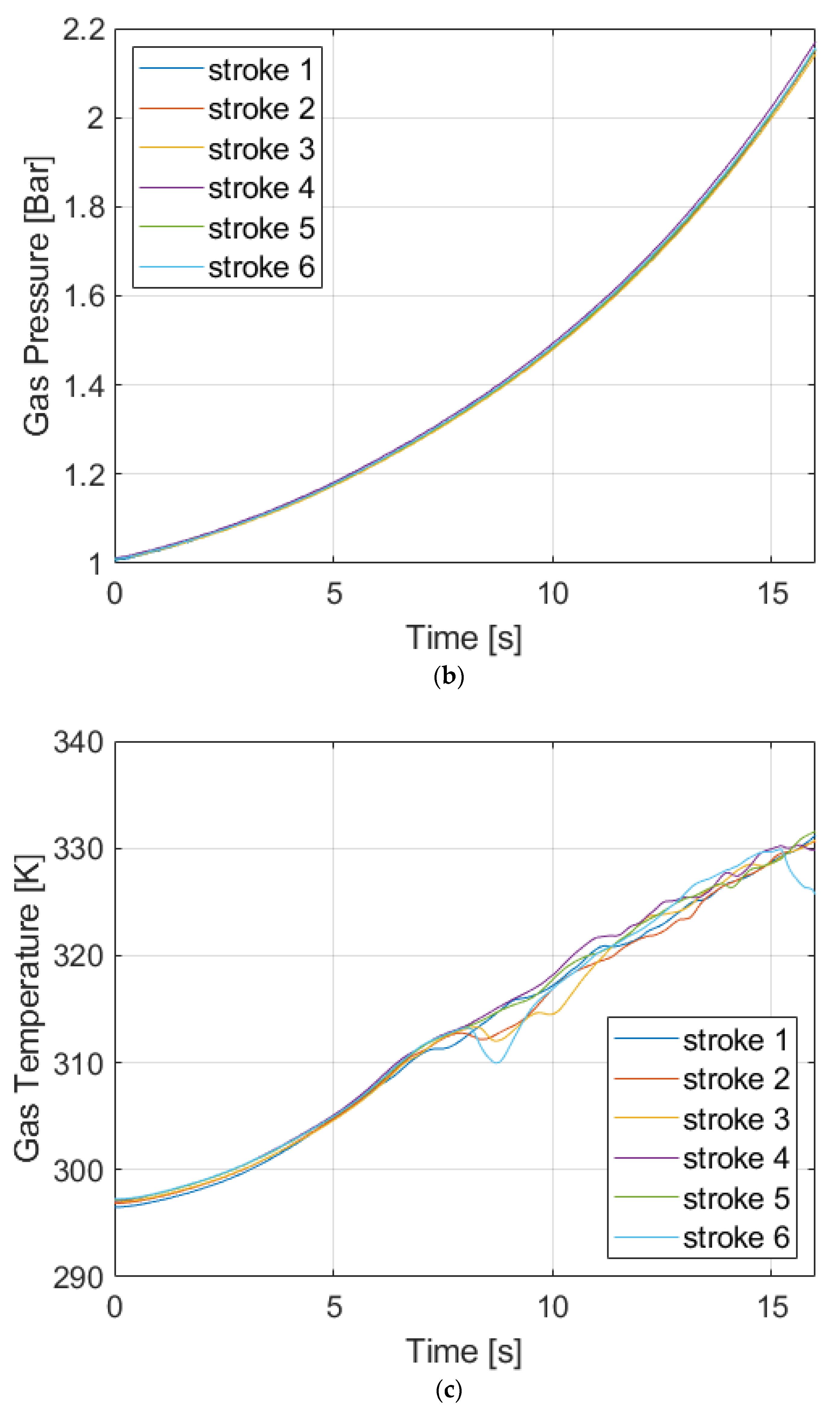
The gas properties data of compression starting from 1 bar (Compression-1) are given in Figure 3a–d. Figure 3a shows the pressure and temperature data over the entire process. To check the repeatability and consistency of the data collected from each stroke, Figure 3b–d compare the pressure, temperature, and volume of each stroke with a closer look. For these plots, the data from the starting point to around the point of pressure ratio of 2 are displayed.
As can be seen in Figure 3b–d, over the six strokes, the gas properties are similar to one another. This means that the liquid piston system has set-up consistent experimental conditions. In Figure 3c, the gas temperature plot shows oscillation in the values. Because the thermocouple used in the current experiment has a fine wire diameter and an exposed tip to ensure the sensitivity, it can be easily affected by the environment. During compression, the liquid piston movement results in air flow. Because the tip of the thermocouple is exposed to the air flow, it may result in oscillations.

3.2. Compression Starting from Elevated Pressure

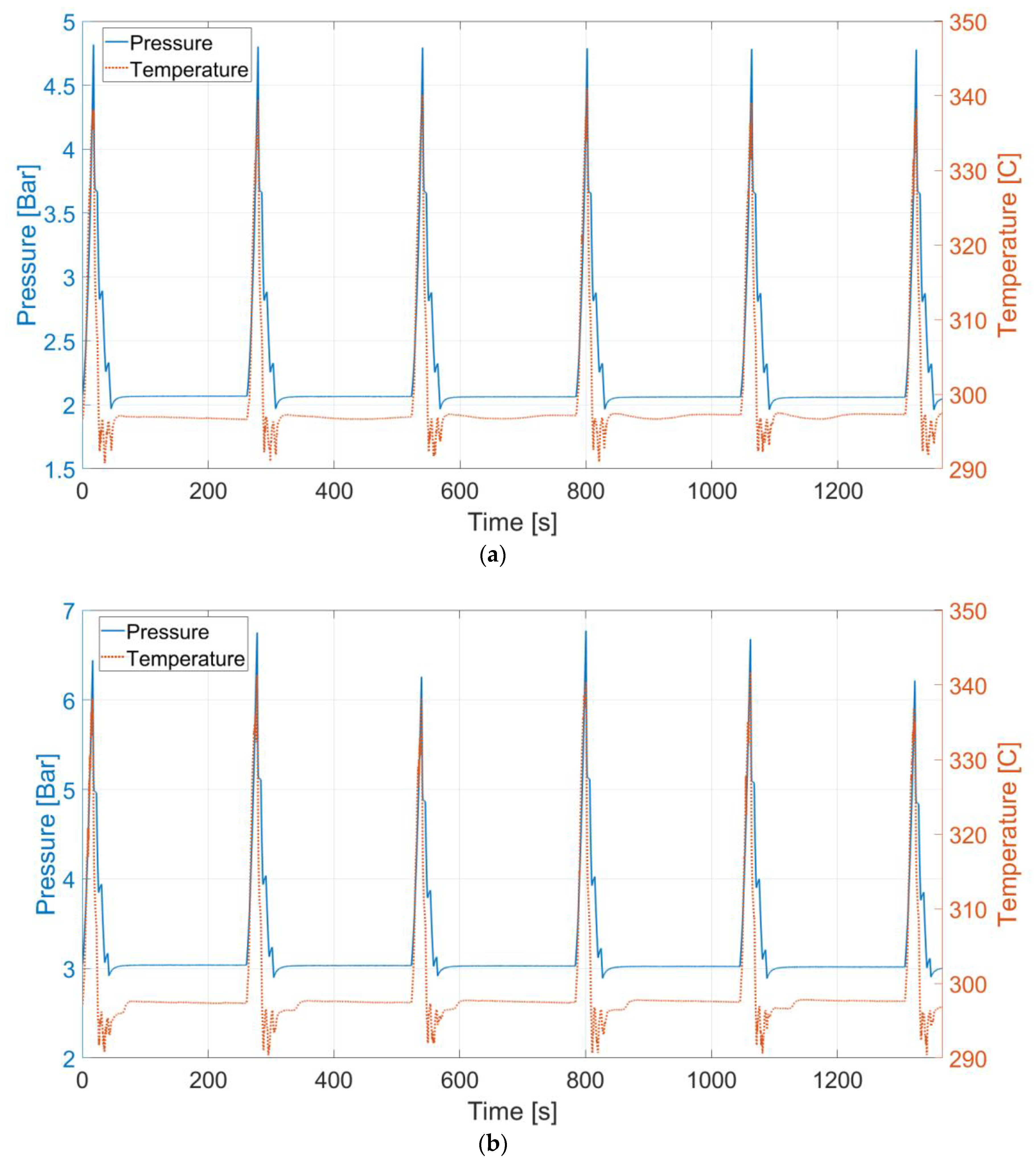
For compression starting from 2 bars (Compression-2) and 3 bars (Compression-3), Figure 4 displays the measured properties of the gas in the same manner as Compression-1 data given in Figure 3a. It is observed that each stroke is less consistent if the initial pressure level is higher. This is expected because the water pumping system at higher pressure requires more power to operate and adds instability. However, near the point where a pressure ratio of 2 is achieved, each stroke matches well with one another.

3.3. Comparison of Atmospheric and Elevated Pressure Compression

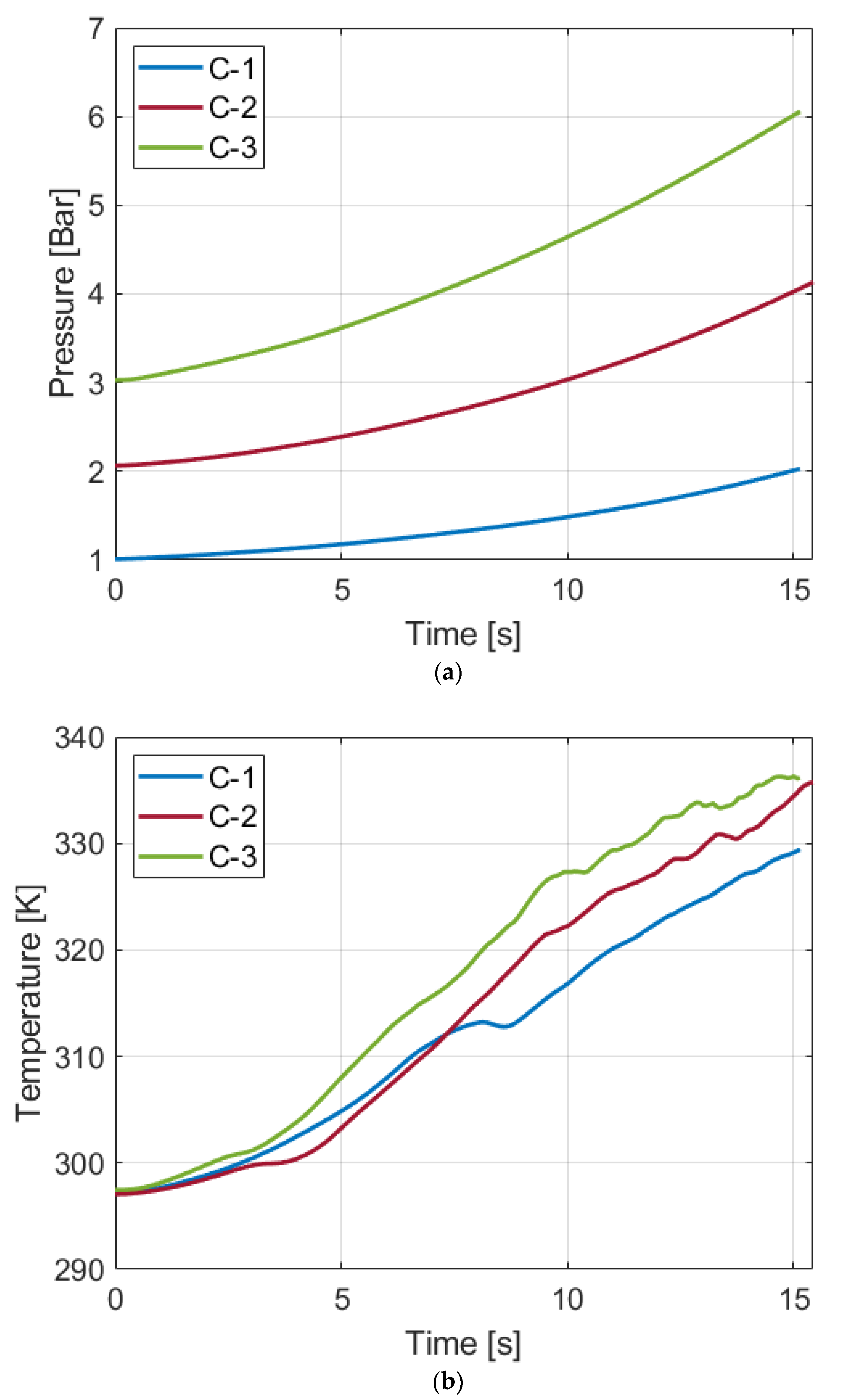
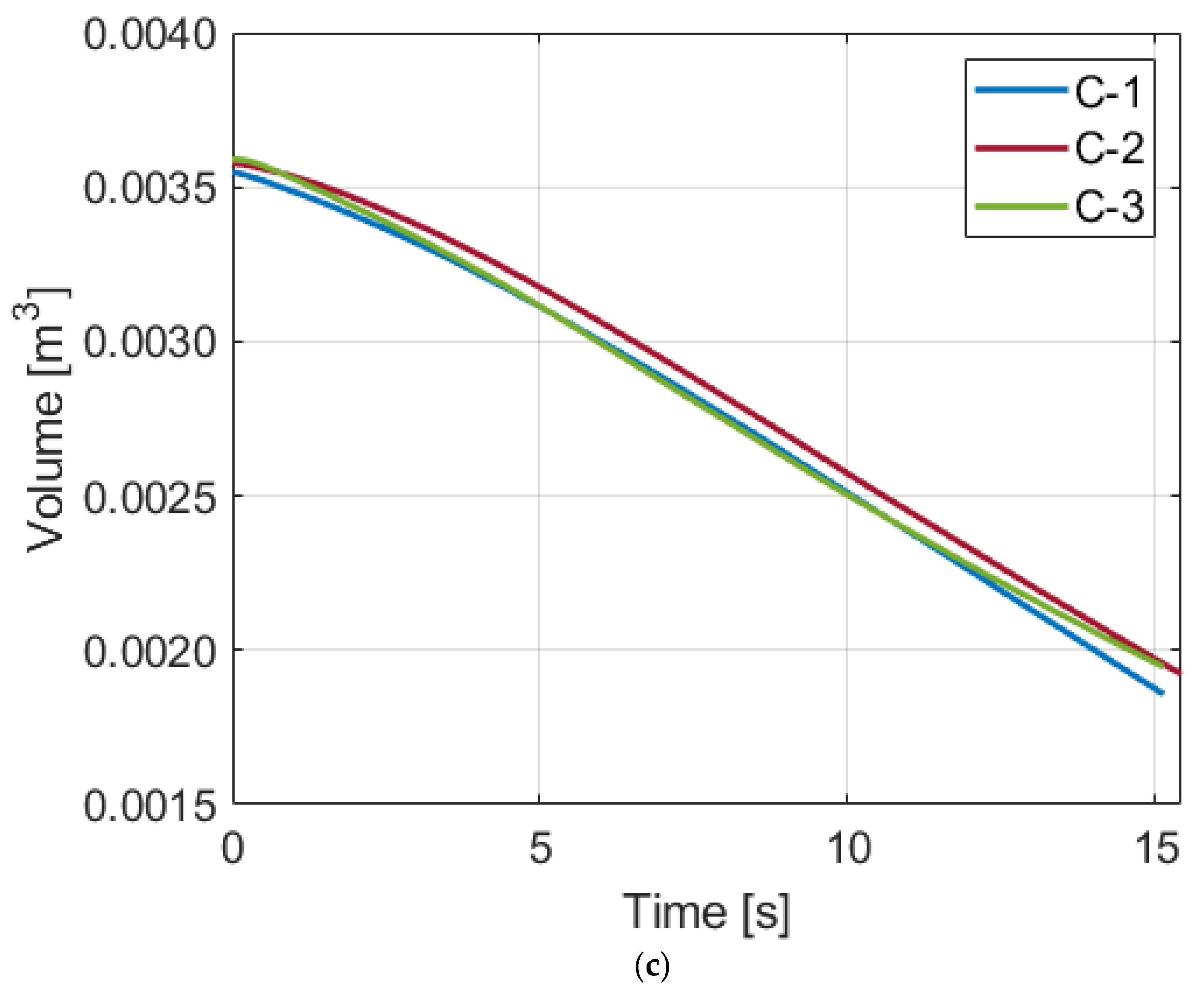
From the second stroke to the sixth stroke, the five strokes are averaged and the trends of the three cases are compared in Figure 5. The averaged data are collected up to the pressure ratio of 2. C-1, C-2, and C-3 in the legend boxes stand for Compression-1, 2, and 3, respectively. The stroke times have been well matched. To be more specific, for Compression-1 and 3, it takes 15.14 s; for Compression-2, 15.43 s. Figure 6b shows the temperature of the gas during the processes. The temperature increments, T f T 0 , for Compression-1, 2, and 3 are 32.35 K, 38.69 K, and 38.66 K, respectively. Comparing Compression-1 and 2, as the initial pressure is elevated, more temperature increase is observed. However, between Compression-2 and 3, it barely shows a difference. The volume profiles are displayed in Figure 5c. There are differences in the initial volumes because the water level is pushed down after setting up elevated initial pressure, and the differences are reflected on the initial volume calculations.
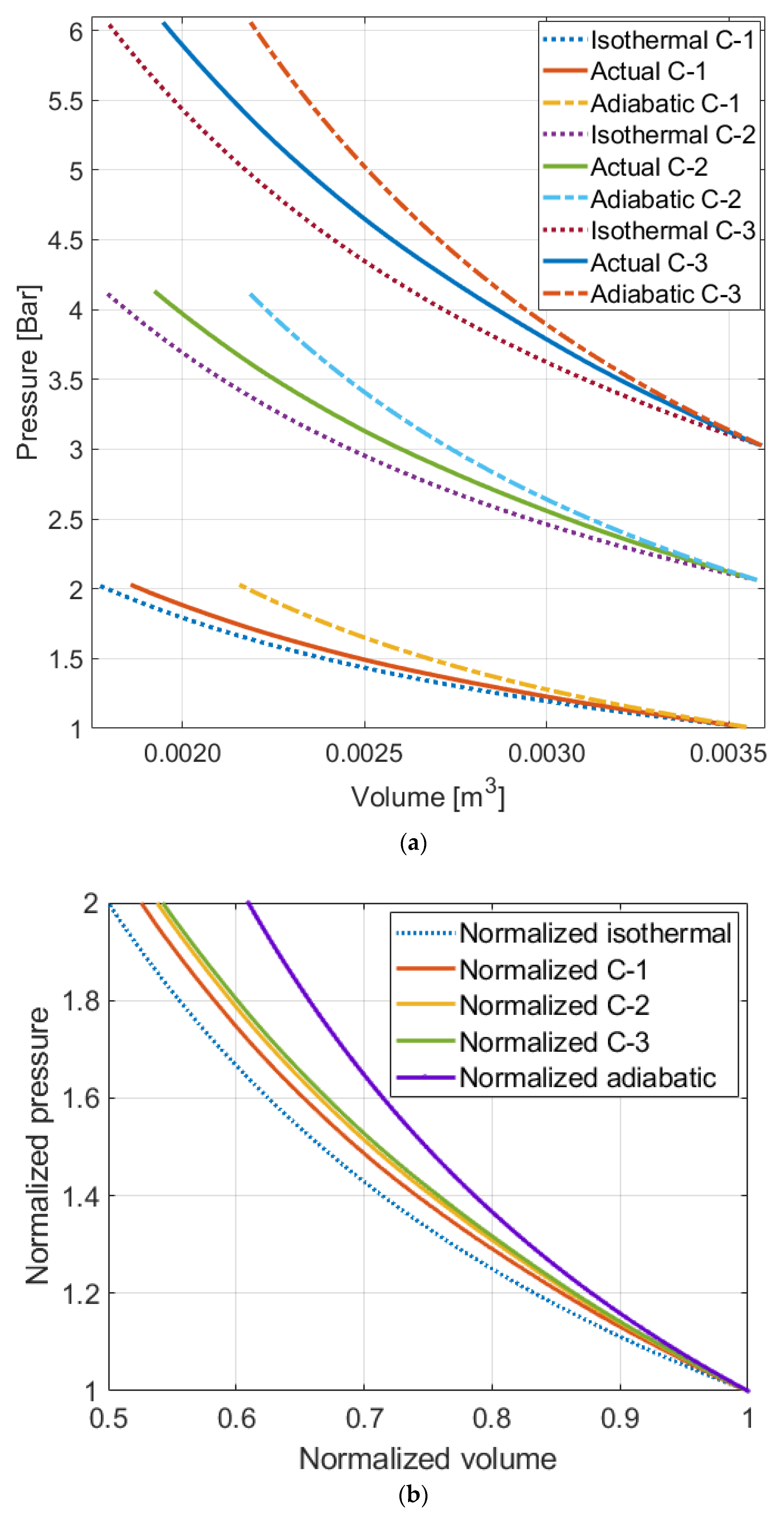
Figure 6a compares the actual pressure–volume experimental data of Compression-1, 2, and 3 to isothermal and adiabatic compression profiles for each initial pressure, and their normalized profiles are displayed in Figure 6b. When the initial pressure is lower, the trajectory is closer to the isothermal trajectory. For at-a-glance comparison, Table 2 presents the starting pressures, temperature increases, and isothermal compression efficiencies. Because the temperature data are local temperatures, it is difficult to determine how close a process is to isothermal compression with the temperature alone. Therefore, by employing Equation (8), isothermal efficiencies of each process are attained for a better comparison.
Comparing the isothermal efficiencies, the compression performed at a higher pressure is less efficient than that at a lower pressure. The difference between Compression-2 and 3 is smaller than the gap between Compression-1 and 2.
To validate this tendency, an uncertainty analysis is performed considering the data processing and possible error sources of the measurement system. For the efficiency results given in Table 2, the average of five strokes is obtained first. Then, the compression efficiencies are calculated out of the averaged data. To complement the efficiency results, which do not deal with deviation, isothermal efficiencies of each stroke are computed as well. The average and standard deviation of each stroke are presented in Table 3.
The standard deviations of each process are small, and the lowest value of a lower- pressure case is greater than the highest value of a higher-pressure case. Hence, it shows the tendency that higher pressure leads to lower efficiency. In terms of the system, volume measurement includes some errors. For air volume measurement, the volume of the water entering the chamber is measured by a sensor. Then, the volume of the air can be calculated by subtracting the water volume from the initial air volume inside the chamber. For Compression-2 and 3, when the chamber is pressurized to higher initial pressure settings, the water level is slightly decreased, which makes a slight initial volume change. Although the changes are reflected in the volume calculations, the manual measurement of the initial volume of air includes some possible errors. Nonetheless, the degree of the errors is minor. Furthermore, data processing with and without reflecting the possible errors is made for comparison, and the same efficiency trend is validated.

4. Discussion

The results show a trend over the tested cases. The higher the pressure level is, the less efficient the process becomes. When pressure is different, one of the phenomena that occurs is gas dissolution. Therefore, to determine whether the dissolution contributes to the variation in the efficiencies at different pressure levels and to properly evaluate the liquid piston performance, the gas dissolution issue needs to be investigated.
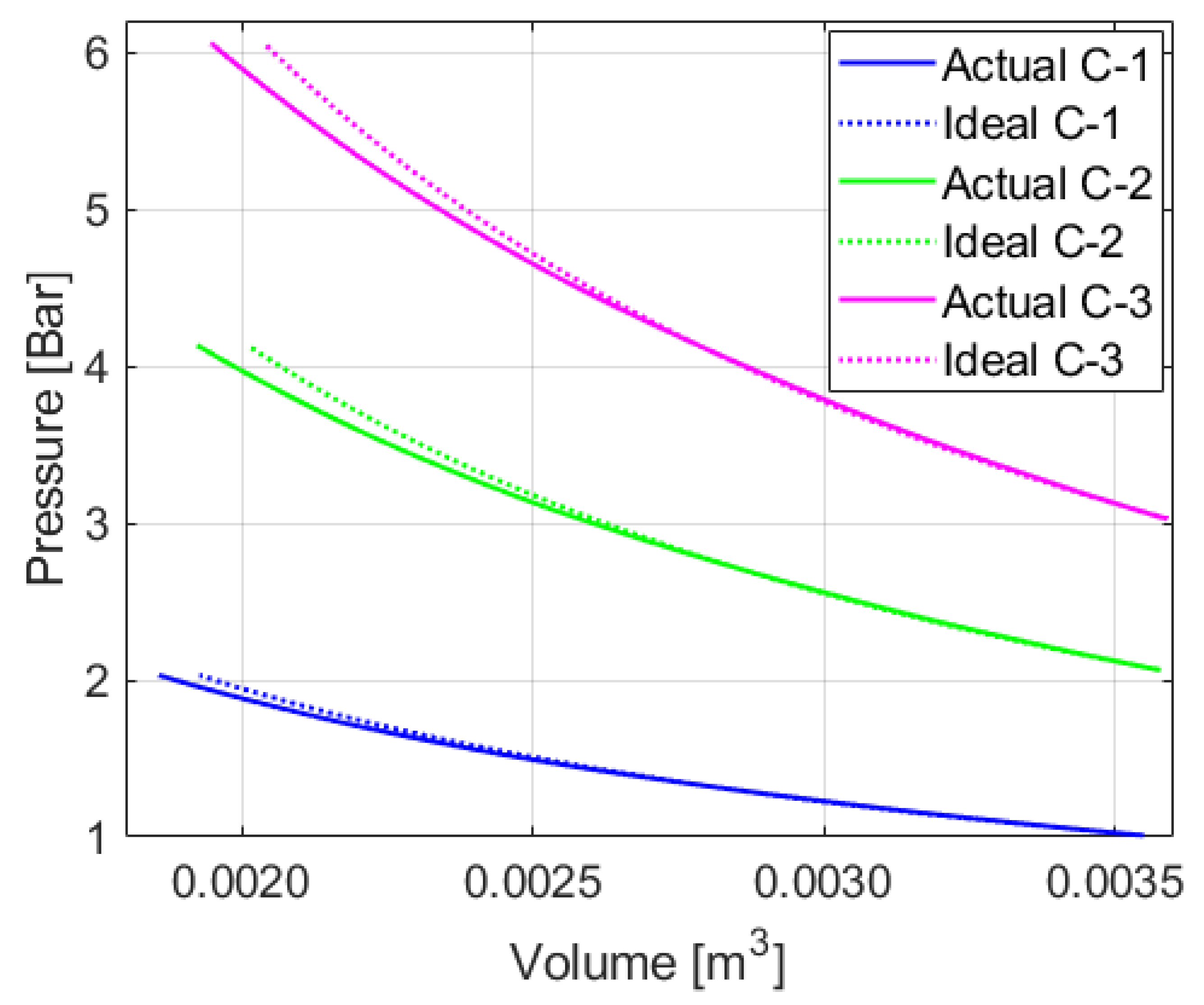
The idea that dissolution takes place during compression can be supported by computing polytropic indices of the compression trajectories. Polytropic indices can be calculated by using Equation (7) and pressure and volume data at two different points. The initial point is used for P 1 and V 1 , and the halfway point of the process for P 2 and V 2 . Figure 7 displays the actual profiles plotted with experimental data and ideal polytropic process profiles from the calculated polytropic indices.
There are mismatches between the actual compression profiles and the ideal polytropic process profiles. Although choosing another point for P 2 and V 2 can adjust the shape of the profiles, it does not make them perfectly overlap the actual profiles. A change in air mass during the process can cause this issue. One factor that brings about air mass change may be leakage because the system is not perfectly leakage-free. In order to identify how significant the leakage issue is, extra tests are performed. The system performs a compression stroke and holds the pressurized state for some extended period for the initial pressure of 1, 2, and 3 bars. Once it becomes thermally stable after 2 min from the beginning of the process, there is no more notable pressure drop, due to cooling down of the air. After that, the pressure drop per minute is less than 0.01 bar, which is negligibly small for the elevated pressure level achieved. The pressure drop ratio per minute is, at most, 0.15% among the collected data. The tested pressure is even higher than the maximum pressure of interest in the main experiments. For the lower-pressure cases, the pressure drop is even smaller. Provided that a single compression stroke takes less than 20 s in this work, the mass loss during compression due to leakage is negligible. The measured gas properties and plots of the data to support this assumption are summarized in the figures and tables in Appendix A.
Another factor that may cause the mismatch is gas dissolution. Because most of gas dissolution takes place within a very short time in such a liquid-based pressurized system [35], the compression time in this work is long enough for the gas dissolution. Thus, it is reasonable to conclude that the dissolution takes place during the process, and it results in the mismatch between the actual profiles and generated polytropic process profiles. Therefore, although polytropic index is a straightforward indicator that shows how efficient a process is, it should not be used in evaluating the efficiency of compression performed with a liquid piston or a similar system that contains a liquid and a gas.
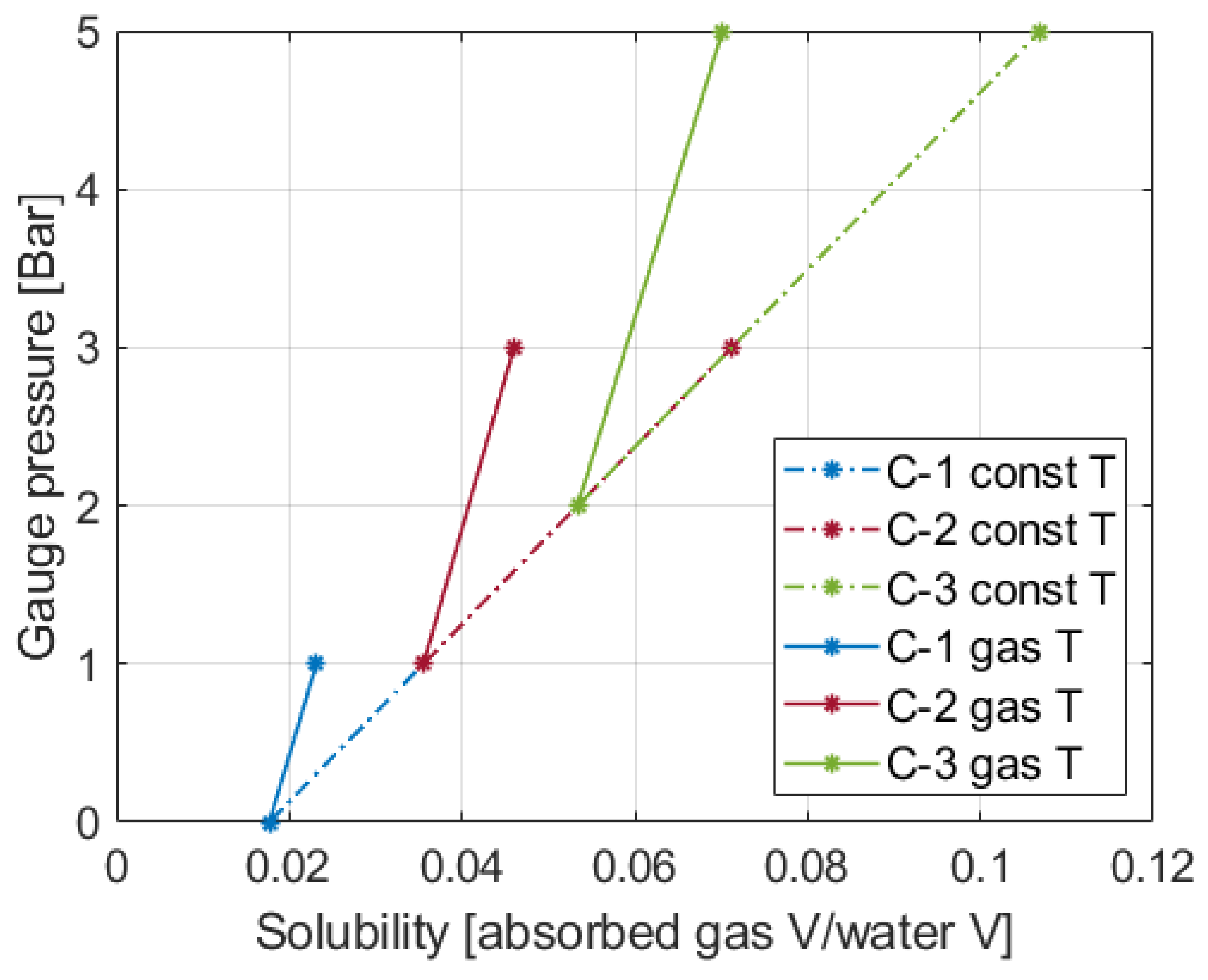
To determine whether the dissolution is a primary factor that causes the efficiency differences of the processes, the gas solubility changes are estimated. There are two parameters that determine air solubility in water: temperature and pressure. However, Henry’s law given in Equation (11) only includes a pressure variable. Therefore, it is difficult to directly employ Equation (11) to estimate how the air mass changes during the process. Thus, simplified estimations are made in the current work with solubility data available on [36] and Henry’s law. Two opposing cases are examined based on two different assumptions. First, temperature change is not considered. Owing to the high specific heat of water and the short compression time, the temperature of the water is assumed to be constant throughout compression. Second, the temperature change is counted. With the air pressure and temperature data, the corresponding solubility values at the beginning and the end of the compression can be attained from the solubility table of [36]. For simplification, the measured temperature data are used in finding the corresponding solubility values. Neither of these cases perfectly simulate the actual circumstances of the system during the compression. However, by examining the two extreme cases, the overall trends can be glanced if there is a consistency.
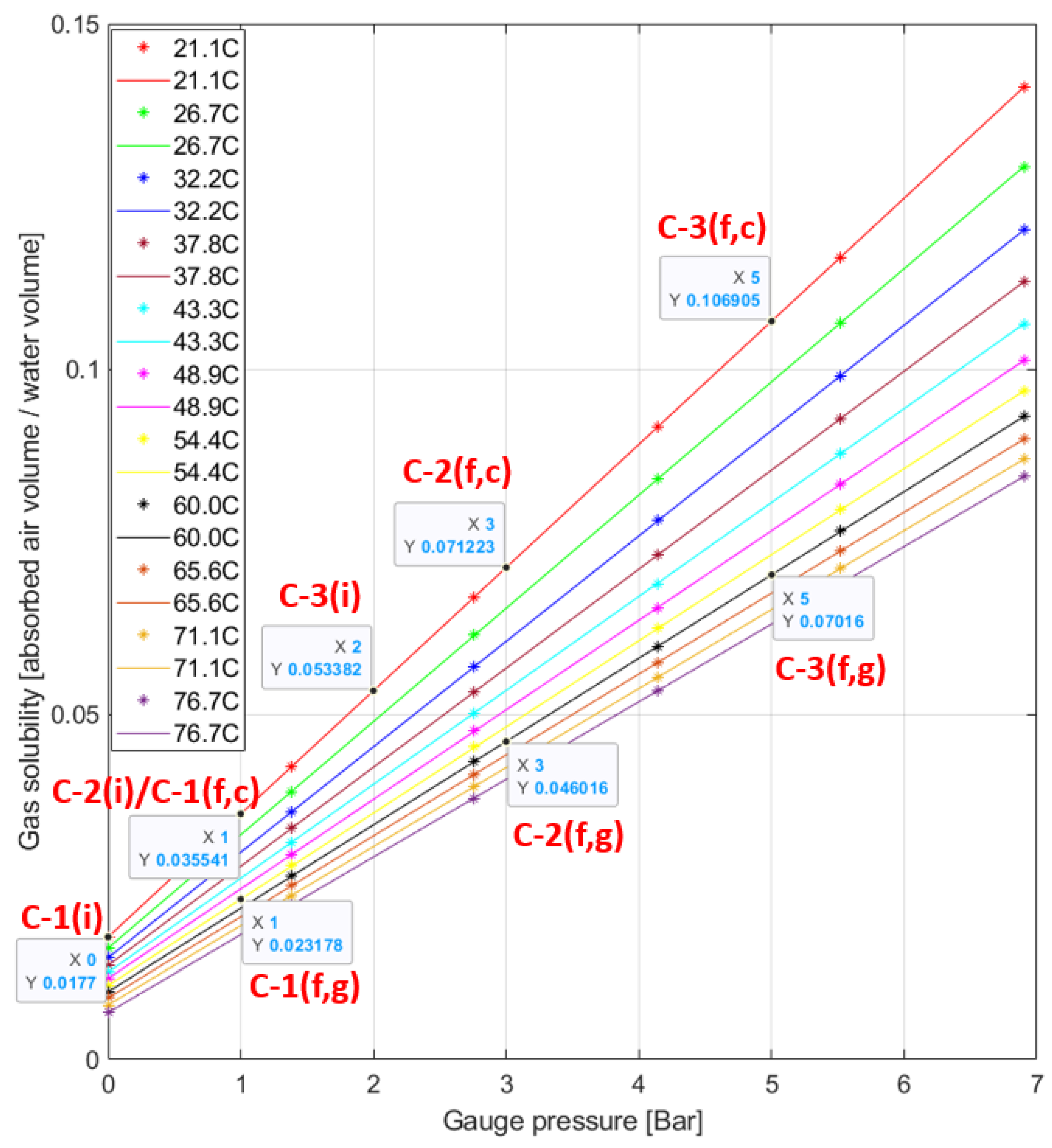
Figure 8 presents the solubilities of air into water at the initial and final points of compression starting from 1, 2, and 3 bars with the pressure ratio of 2. The plot is drawn based upon the data from [36], and how the data are selected is explained in the Appendix A with a supplementary figure. As the data are given in the gauge pressure, Compression-1, 2, and 3 start from 0, 1, and 2 gauge bar and end at 1, 3, and 5 gauge bar, respectively. For the final points, there are two points for each process. The points named const T in the legend box are for the constant-temperature assumption, and the points named gas T are for the second assumption that the system temperature changes the same as the gas temperature. Table 4 summarizes the solubility at the marked points and the amount of increase from the initial points to the final points along with the reduced work input by the dissolution. If the constant temperature is assumed, the solubility increase of Compression-2 is twice as much as Compression-1. For Compression-3, the increase is three times as much as Compression-1. If the temperature is the same as the gas temperature, compared to Compression-1, increases of about 1.91 times for Compression-2 and 3.06 times for Compression-3 are observed, and a lower amount of air is absorbed due to the higher temperature. A similar trend of the proportional increase with the initial pressure is observed under both cases.
Regarding the reduced work input, the higher pressure leads to the greater decrease in work input due to an increased amount of the dissolved gas volume. For both cases, Compression-2 and 3 show roughly 4 times and 9 times the reduced work, compared to Compression-1. Considering that the compression work input of Compression-2 and 3 takes about 2 times and 3 times the work input of Compression-1, the ratios of the reduced work input to the compression work input of Compression-2 and 3 are about 2 and 3 times the ratio of Compression-1, respectively. Despite the greater reduced work of the processes starting from the elevated pressures, Compression-2 and 3 have lower isothermal efficiency than Compression-1. This implies that the gas dissolution is not the primary reason for the different isothermal efficiencies of the present work. Therefore, the results observed in this work of the higher isothermal efficiency of the compression with the lower initial pressure cannot be explained by air dissolution alone. A possible explanation is that air at higher pressure has a greater air mass in a fixed volume. Thus, it may change the motion of air during compression and affect the degree of convection. To accurately identify the full reason for the differences in the efficiency of processes with various initial pressures, microscopic investigation on the dynamics of air inside the chamber should be performed, which is beyond the scope of this work.
The air dissolution complicates the efficiency evaluation with Equation (8). This is because the dissolution compromises the work output. For an energy storage application, the compressed air has to be expanded to restore the energy. When the compressed air is removed from the compressor, the total mass of the compressed air leaving the chamber is less than the original mass before the compression due to the loss caused by dissolution. This will lead to a reduced energy restored in the discharging process. In other words, although the dissolution is beneficial for the isothermal efficiency on paper obtained using Equation (8), the actual efficiency based on how much work can be restored is different from the calculated value. Because each compression process has different dissolved amounts, the compromised work output may vary as well. To evaluate how much efficiency is compromised, the output work needs to be quantified. Because of the difficulty of predicting the exact expansion trajectory without empirical work, the volume of air after the expansion is quantified and compared by estimating the mass changes of the air. The ideal gas equation and the solubility data from [36] enable the volume quantification. The absorbed gas volume varies with the water volume.
Figure 9 displays the mass of the air that is not dissolved into the water and remains as a gas above the water. This estimation needs water volume in a system and air solubility. For water volume, the volume is assumed to be the same as the initial air volume in the chamber. For solubility changes, the solubilities under the constant-temperature assumption are used. To perform a proportional comparison of the three processes, the mass and pressure values are normalized by dividing by the initial values. At the target pressure, the ratios of the mass to the initial mass for Compression-1, 2, and 3 are 94.57%, 88.96%, and 83.81%, respectively. After expansion up to the initial pressure of the pre-compression status, the restorable volume will also be 94.57%, 88.96%, and 83.81% of the initial volume, respectively. This means that an increased solubility at the higher pressure results in a greater compromise in the work output unless the expansion takes place in the same chamber and the dissolved air is fully restored.
Separately, a significant change in the water volume also has an impact on the soluble amount. Table 5 presents the variations in the air mass ratios with different water volumes.
When the water volume is smaller, the absolute amount of the dissolved air mass is smaller, leading to a larger air mass ratio. In contrast, when the water volume is larger, the ratios become smaller. Furthermore, the differences in the ratios between the processes become greater, which results in a significantly lower value for Compression-3 when the water volume is 1.5 times the initial air volume. Hence, using the minimum amount of water will help secure the restorable work output. Although those numbers are generated based on a simple simulation model, it implies how the volume of water can affect the system efficiency.
The dissolution is advantageous for the isothermal compression efficiency on paper calculated using Equation (8) because it reduces the volume of the air inside the chamber as the pressure increases. Thus, the process with higher initial pressure benefits more from an increased dissolution. However, despite a greater dissolution, the higher pressure shows the lower efficiency. On top of the lower efficiency at the higher pressure, the greater dissolution will lead to a lower restoration of the output energy. Hence, for the overall system including the energy discharging stage considered, there will be an even larger gap in the actual efficiencies than their calculated values. Although the higher-pressure process has the advantage of having a higher power to perform the charging/discharging process faster, it shows compromised performance with regard to overall efficiency. However, this should not depreciate the efficacy of the liquid piston compressor. The main strength of the liquid piston compressor is that various heat transfer enhancement techniques can be easily integrated regardless of the dissolution.
There are limitations to the current study. As referred earlier, the overall temperature of the air and the dissolved air mass cannot be obtained with the ideal gas equation, because each one requires the value of the other one. As the simplified estimation of the total solubility changes is used for the amount of the dissolved air, errors from the simplification may be inevitable. In addition, there is room for improvement in efficiency analysis. The efficiency, η i s o , is calculated by comparing the isothermal work, W i s o t h e r m a l , and the actual work, W a c t u a l . In the current study, the mass change is not considered in calculating W i s o t h e r m a l , while W a c t u a l is calculated from the data collected from the real experiment where dissolution takes place. If the isothermal profile reflects the mass change as well, it could possibly lead to a different conclusion.
Nevertheless, to the author’s best knowledge, this is the first work to experimentally investigate how the initial pressure level affects the isothermal compression efficiency when the pressure ratio is the same and to determine whether the gas dissolution is associated with the different compression efficiencies. Furthermore, by testing compression at different initial pressures, an initial attempt is made to simulate the applicability of the liquid piston compressor to a multi-stage compression system. The examined pressure ranges are quite limited to lower pressures because Henry’s law is not applicable if the pressure goes up high enough [40]. At higher pressures, the trend may be different from the evaluated range of the current work. Compression at much higher levels to study how the trend changes will be an interesting topic for future research.

5. Conclusions

The impacts of different initial pressures on liquid piston compression are investigated in this paper by performing compressions starting from 1 bar, 2 bars, and 3 bars with the same pressure ratio of 2. At elevated pressures, the processes result in higher temperature increases over the compression that starts from the atmospheric pressure, whereas there is no notable difference in temperature rise between compressions starting at 2 bars and 3 bars. Regarding compression efficiency, the compressions at higher pressure lead to lower isothermal efficiencies. Experimental results have shown that the isothermal efficiencies of Compression-1, 2, and 3 processes are 89.1%, 85.0%, and 83.5%, respectively. To identify the cause of the efficiency differentiation, gas solubility changes of the three compression processes are quantified based on simple estimation models. Because the gas solubility is proportional to the pressure, the higher initial pressure process has more gas absorbed in the water. Despite the increased solubility, which is beneficial for isothermal efficiency calculations on paper, the compression processes at higher pressures have shown lower efficiencies than the compression starting from the atmospheric pressure. Hence, the dissolution is not the primary reason for the lower compression efficiency at higher initial pressure. Because the air behaves differently during compression depending on the pressure and the mass in the chamber, a comprehensive analysis on the dynamics of the air in the chamber may help clarify the cause of the phenomenon.
Although the dissolution is advantageous for the isothermal efficiency calculations on paper, the dissolved mass may further compromise the overall system efficiency than the calculated values. This is because the isothermal efficiency can be calculated in a conventional manner without considering air mass changes caused by the dissolution. For a real application that includes the energy discharging process, dissolved mass results in a reduced volume of air after expansion and it leads to less energy output. Assuming the system contains the same water volume as the initial air volume, the masses of the air after compressions starting at 1, 2, and 3 bars are estimated to be 94.57%, 88.96%, and 83.81% of the initial masses prior to the compression, respectively, which further compromises the system efficiency than the calculated compression efficiencies discounting dissolution. In conclusion, even though the dissolution is not a major factor that results in efficiency decrease at a higher pressure level on paper, it actually further degrades the overall system efficiency.

Author Contributions

System design, B.A.; investigation, B.A.; formal analysis, B.A.; writing—original draft, B.A.; conceptualization, P.I.R.; supervision, P.I.R.; writing—review and editing, P.I.R. All authors have read and agreed to the published version of the manuscript.

Funding

This research received no external funding.

Data Availability Statement

Data available on request due to privacy.

Conflicts of Interest

The authors declare no conflict of interest.

Nomenclature

Nomenclature
A s Surface area
C v Specific heat
k H Proportionality constant
m Mass
m g a s Gas mass
nPolytropic index
P Pressure
P 0 Initial pressure
P 1 Pressure at point 1
P 2 Pressure at point 2
P f Final pressure
P g a s Gas pressure
P c m i n Pressure change for a minute
P r Pressure ratio
P r m i n Pressure ratio for a minute
Q ˙ Heat transfer rate
R Gas constant
S 0 Initial gas solubility
S f Final gas solubility
S f , c o n s t Final gas solubility with constant-temperature assumption
S f , g a s Final gas solubility with gas temperature assumption
S g a s Gas solubility
T Temperature
T 0 Initial temperature
T f Final temperature
T g a s Gas temperature
T i Temperature at current step
T i 1 Temperature at previous step
T Temperature of surroundings
t Time
U ˙ Internal energy rate
U h Overall heat transfer coefficient
V Volume
V 0 Initial volume
V 0 , g a s Initial gas volume
V 1 Volume at point 1
V 2 Volume at point 2
V f Final volume
V f , i s o Final volume of isothermal compression
V g a s Gas volume
V i Volume at current step
V i 1 Volume at previous step
V w Volume of water
W a c t u a l Actual work
W c o m p Compression work
W c o o l i n g Cooling work
W d i s Work from dissolution
W d i s , c o n s t Dissolution work with constant-temperature assumption
W d i s , g a s Dissolution with gas temperature assumption
W i s o t h e r m a l Isothermal compression work
W ˙ c o m p Compression work rate
Greek letters
η i s o Isothermal compression efficiency
η i s o ¯ Average isothermal compression efficiency
σ i s o Standard deviation of isothermal efficiency
Abbreviation
CAESCompressed air energy storage
A-CAESAdiabatic compressed air energy storage
D-CAESDiabatic compressed air energy storage
I-CAESIsothermal compressed air energy storage
Compression-1Compression starting from 1 bar
Compression-2Compression starting from 2 bar
Compression-3Compression starting from 3 bar
C-1Compression-1 (used in plot legend)
C-2Compression-2 (used in plot legend)
C-3Compression-3 (used in plot legend)
Hold-1Hold process starting from 1 bar
Hold-2Hold process starting from 2 bar
Hold-3Hold process starting from 3 bar

Appendix A

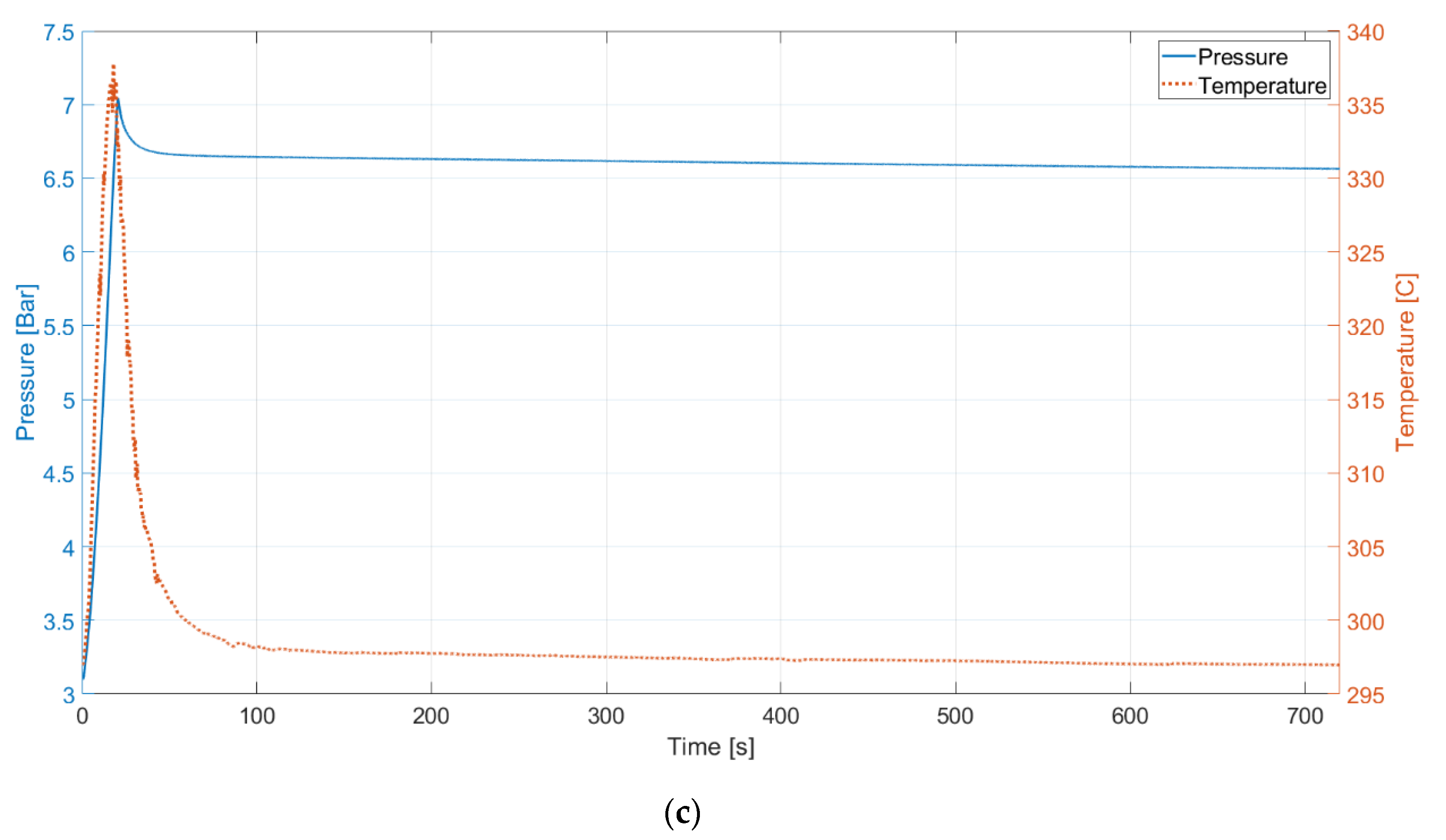
Figure A1 and Table A1 are supplementary materials to substantiate the fact that the leakage of the system is negligible. Compressions are performed from the initial pressure of 1, 2, and 3 bars. Then, without performing expansion, the pressurized state is held for an extended time stretch. The pressure drops of the three cases per minute are summarized in Table A1. The percentages of the current pressure to the pressure measured a minute ago are given in the same table. It takes about two minutes to be nearly thermally stable after compression starts. From the point, the pressure drop per minute does not exceed 0.01 bar at any point. In terms of pressure drop percentage, 99.85% is the smallest value. Overall, the pressure drop is smaller when the pressure is lower. The held pressures for the leakage test are higher than the pressure of interest of the main experiment. Furthermore, the stroke time of the main experiment takes less than 20 s. Thus, the pressure drops that occur in the main tests are expected to be smaller than those values. Thus, the mass losses during the test due to leakage are negligible.
Figure A1. Pressure and Measured Temperature of Compression-and-Hold Process Starting from (a) 1 Bar, (b) 2 Bar, and (c) 3 Bar for Extended Time Stretch (12 Minutes).
Energies 16 01921 g0a1aEnergies 16 01921 g0a1b
Table A1. Pressure Data for Hold-1, 2, and 3.
PRESSURE
Hold-1Hold-2Hold-3
Time [s][Bar] P c m i n u t e P r m i n u t e [Bar] P c m i n u t e P r m i n u t e [Bar] P c m i n u t e P r m i n u t e
602.928894 5.017834 6.656374
1202.924585−0.0043199.85%5.008354−0.0094899.81%6.641895−0.0144899.78%
1802.922689−0.001999.94%5.000769−0.0075899.85%6.633276−0.0086299.87%
2402.920103−0.0025999.91%4.995254−0.0055299.89%6.625347−0.0079399.88%
3002.917173−0.0029399.90%4.988186−0.0070799.86%6.617591−0.0077699.88%
3602.915449−0.0017299.94%4.982154−0.0060399.88%6.609145−0.0084599.87%
4202.912347−0.003199.89%4.976638−0.0055299.89%6.599664−0.0094899.86%
4802.910106−0.0022499.92%4.970777−0.0058699.88%6.593976−0.0056999.91%
5402.907176−0.0029399.90%4.964744−0.0060399.88%6.586047−0.0079399.88%
6002.90459−0.0025999.91%4.959573−0.0051799.90%6.578118−0.0079399.88%
6602.902866−0.0017299.94%4.955092−0.0044899.91%6.571051−0.0070799.89%
7202.899936−0.0029399.90%4.949748−0.0053499.89%6.564846−0.0062199.91%
Figure A2 is a supplementary material to clarify how the solubility estimation was made. The asterisk marks are the data points of [36], and the lines are drawn connecting the points at the lowest and the highest pressure points to estimate the solubility values between the data points. The initial points and final points with the two different assumptions of Compression-1, 2, and 3 are marked on the lines. In Figure A2, (i) stands for the initial point, (f,c) for the final point with the constant-temperature assumption, and (f,g) for the final point with the changing-temperature assumption. Because the dataset does not have exactly same values as the experimental data, the close values that represent the temperature changes well are chosen. The measured and chosen temperature values are presented in Table A2.
Figure A2. Solubility Data.
Energies 16 01921 g0a2
Table A2. Pressure Data for Hold-1, 2, and 3.
CompressionMeasured T0 [°C]Chosen T0 [°C]Measured Tf [°C]Chosen Tf [°C]
Compression-123.921.156.354.4
Compression-223.921.162.660.0
Compression-324.321.163.060.0
As the temperature data are collected by a thermocouple installed at a specific location, they are local temperature and do not represent the overall temperature of the system. Because of the air mass change caused by dissolution, the air temperature cannot be calculated by the ideal gas equation. Thus, assuming the experimental temperature data represent the overall system temperature, the solubilities are estimated.
For the first assumption that temperature change is not considered and pressure is the only variable, it has a linear profile. On the contrary, for the second assumption that the gas temperature is considered, it is highly difficult to accurately determine the solubility changing profiles throughout the compression. Thus, for the problem simplification, it is assumed that the solubility differences between the two points are the total solubility changes, and the solubility changes linearly with pressure between the two points.

References

  1. Mertz, O.; Halsnæs, K.; Olesen, J.E.; Rasmussen, K. Adaptation to Climate Change in Developing Countries. Environ. Manag. 2009, 43, 743–752. [Google Scholar] [CrossRef] [PubMed] [Green Version]
  2. Renewable Energy Explained–U.S. Energy Information Administration (EIA). Available online: https://www.eia.gov/energyexplained/renewable-sources/ (accessed on 4 October 2022).
  3. Evans, A.; Strezov, V.; Evans, T.J. Assessment of Utility Energy Storage Options for Increased Renewable Energy Penetration. Renew. Sustain. Energy Rev. 2012, 16, 4141–4147. [Google Scholar] [CrossRef]
  4. Park, J.-K.; Ro, P.I.; He, X.; Mazzoleni, A.P. Analysis and Proof-of-Concept Experiment of Liquid-Piston Compression for Ocean Compressed Air Energy Storage (OCAES) System. In Proceedings of the 2nd Marine Energy Technology Symposium, Seattle, WA, USA, 15 April 2014. [Google Scholar]
  5. Cavallo, A.J. Energy Storage Technologies for Utility Scale Intermittent Renewable Energy Systems. J. Sol. Energy Eng. 2001, 123, 387–389. [Google Scholar] [CrossRef]
  6. Cavallo, A. Controllable and Affordable Utility-Scale Electricity from Intermittent Wind Resources and Compressed Air Energy Storage (CAES). Energy 2007, 32, 120–127. [Google Scholar] [CrossRef]
  7. Crotogino, F.; Mohmeyer, K.-U.; Scharf, R. Huntorf CAES: More than 20 Years of Successful Operation. In Proceedings of the SMRI Spring Meeting, Orlando, FL, USA, 23–25 April 2001; Volume 2001. [Google Scholar]
  8. Caralis, G.; Christakopoulos, T.; Karellas, S.; Gao, Z. Analysis of Energy Storage Systems to Exploit Wind Energy Curtailment in Crete. Renew. Sustain. Energy Rev. 2019, 103, 122–139. [Google Scholar] [CrossRef]
  9. Kim, Y.-M.; Lee, J.-H.; Kim, S.-J.; Favrat, D. Potential and Evolution of Compressed Air Energy Storage: Energy and Exergy Analyses. Entropy 2012, 14, 1501–1521. [Google Scholar] [CrossRef]
  10. Patil, V.C.; Ro, P.I. Energy and Exergy Analysis of Ocean Compressed Air Energy Storage Concepts. J. Eng. 2018, 2018, e5254102. [Google Scholar] [CrossRef] [Green Version]
  11. Budt, M.; Wolf, D.; Span, R.; Yan, J. Compressed Air Energy Storage–An Option for Medium to Large Scale Electrical-Energy Storage. Energy Procedia 2016, 88, 698–702. [Google Scholar] [CrossRef]
  12. Van de Ven, J.D.; Li, P.Y. Liquid Piston Gas Compression. Appl. Energy 2009, 86, 2183–2191. [Google Scholar] [CrossRef]
  13. Qin, C.; Loth, E. Liquid Piston Compression Efficiency with Droplet Heat Transfer. Appl. Energy 2014, 114, 539–550. [Google Scholar] [CrossRef]
  14. Qin, C.; Loth, E.; Li, P.; Simon, T.; Van de Ven, J. Spray-Cooling Concept for Wind-Based Compressed Air Energy Storage. J. Renew. Sustain. Energy 2014, 6, 043125. [Google Scholar] [CrossRef]
  15. Electricity Generation from Wind–U.S. Energy Information Administration (EIA). Available online: https://www.eia.gov/energyexplained/wind/electricity-generation-from-wind.php (accessed on 4 February 2023).
  16. Wind Energy. Available online: https://www.irena.org/Energy-Transition/Technology/Wind-energy (accessed on 4 February 2023).
  17. Zhang, X.; Xu, Y.; Zhou, X.; Zhang, Y.; Li, W.; Zuo, Z.; Guo, H.; Huang, Y.; Chen, H. A Near-Isothermal Expander for Isothermal Compressed Air Energy Storage System. Appl. Energy 2018, 225, 955–964. [Google Scholar] [CrossRef]
  18. Yan, B.; Wieberdink, J.; Shirazi, F.; Li, P.Y.; Simon, T.W.; Van de Ven, J.D. Experimental Study of Heat Transfer Enhancement in a Liquid Piston Compressor/Expander Using Porous Media Inserts. Appl. Energy 2015, 154, 40–50. [Google Scholar] [CrossRef]
  19. Wieberdink, J.; Li, P.Y.; Simon, T.W.; Van de Ven, J.D. Effects of Porous Media Insert on the Efficiency and Power Density of a High Pressure (210 bar) Liquid Piston Air Compressor/Expander–An Experimental Study. Appl. Energy 2018, 212, 1025–1037. [Google Scholar] [CrossRef]
  20. Patil, V.C.; Liu, J.; Ro, P.I. Efficiency Improvement of Liquid Piston Compressor Using Metal Wire Mesh for Near-Isothermal Compressed Air Energy Storage Application. J. Energy Storage 2020, 28, 101226. [Google Scholar] [CrossRef]
  21. Khaljani, M.; Vennard, A.; Harrison, J.; Surplus, D.; Murphy, A.; Mahmoudi, Y. Experimental and Modelling Analysis of Efficiency Enhancement in a Liquid Piston Gas Compressor Using Metal Plate Inserts for Compressed Air Energy Storage Application. J. Energy Storage 2021, 43, 103240. [Google Scholar] [CrossRef]
  22. Patil, V.C.; Acharya, P.; Ro, P.I. Experimental Investigation of Water Spray Injection in Liquid Piston for Near-Isothermal Compression. Appl. Energy 2020, 259, 114182. [Google Scholar] [CrossRef]
  23. Ahn, B.; Patil, V.C.; Ro, P.I. Effect of Integrating Metal Wire Mesh with Spray Injection for Liquid Piston Gas Compression. Energies 2021, 14, 3723. [Google Scholar] [CrossRef]
  24. Patil, V.C.; Ro, P.I. Experimental Study of Heat Transfer Enhancement in Liquid Piston Compressor Using Aqueous Foam. Appl. Therm. Eng. 2020, 164, 114441. [Google Scholar] [CrossRef]
  25. Ren, T.; Xu, W.; Cai, M.; Wang, X.; Li, M. Experiments on Air Compression with an Isothermal Piston for Energy Storage. Energies 2019, 12, 3730. [Google Scholar] [CrossRef]
  26. Ren, T.; Xu, W.; Jia, G.-W.; Cai, M. A Novel Isothermal Compression Method for Energy Conservation in Fluid Power Systems. Entropy 2020, 22, 1015. [Google Scholar] [CrossRef] [PubMed]
  27. Li, C.; Wang, H.; He, X.; Zhang, Y. Experimental and Thermodynamic Investigation on Isothermal Performance of Large-Scaled Liquid Piston. Energy 2022, 249, 123731. [Google Scholar] [CrossRef]
  28. Zhang, C.; Li, P.Y.; Van de Ven, J.D.; Simon, T.W. Design Analysis of a Liquid-Piston Compression Chamber with Application to Compressed Air Energy Storage. Appl. Therm. Eng. 2016, 101, 704–709. [Google Scholar] [CrossRef] [Green Version]
  29. Patil, V.C.; Acharya, P.; Ro, P.I. Experimental Investigation of Heat Transfer in Liquid Piston Compressor. Appl. Therm. Eng. 2019, 146, 169–179. [Google Scholar] [CrossRef]
  30. Hu, S.; Xu, W.; Cai, M.; Jia, G. Energy Efficiency and Power Density Analysis of a Tube Array Liquid Piston Air Compressor/Expander for Compressed Air Energy Storage. J. Energy Storage 2022, 55, 105674. [Google Scholar] [CrossRef]
  31. Single, vs. Multi-Stage Compressors. Available online: https://cascousa.com/compressed-air-101/types-of-compressors/single-versus-multi-stage-compressors/ (accessed on 7 April 2022).
  32. Budt, M.; Wolf, D.; Span, R.; Yan, J. A Review on Compressed Air Energy Storage: Basic Principles, Past Milestones and Recent Developments. Appl. Energy 2016, 170, 250–268. [Google Scholar] [CrossRef]
  33. Wolf, D. Methods for Design and Application of Adiabatic Compressed Air Energy Storage Based on Dynamic Modeling. 2011. Available online: https://www.osti.gov/etdeweb/biblio/21461477 (accessed on 4 February 2023).
  34. Huang, L.; Simon, T.W.; Li, P.Y.; Hummelt, E.J. Analysis of Dissolved Gas in the Application of Liquid Piston Gas Compression. In Proceedings of the 1st Thermal and Fluid Engineering Summer Conference, TFESC, New York, NY, USA, 9–12 August 2015; pp. 9–12. [Google Scholar]
  35. Xu, W.; Garvey, S.D.; Ren, T.; Hu, Y. Dynamics of Dissolution for Underwater Compressed Air Energy Storage. In Proceedings of the 2019 Offshore Energy and Storage Summit (OSES), Brest, France, 10–12 July 2019; pp. 1–5. [Google Scholar]
  36. Engineering ToolBox (2004) Solubility of Air in Water. Available online: https://www.engineeringtoolbox.com/air-solubility-water-d_639.html (accessed on 11 November 2022).
  37. Çengel, Y.; Boles, M. Thermodynamics An Engineering Approach, 2nd ed.; McGraw-Hill, Inc.: Hightstown, NJ, USA, 1994; ISBN 0-07-911652-3. [Google Scholar]
  38. Zhang, C.; Yan, B.; Wieberdink, J.; Li, P.Y.; Van de Ven, J.D.; Loth, E.; Simon, T.W. Thermal Analysis of a Compressor for Application to Compressed Air Energy Storage. Appl. Therm. Eng. 2014, 73, 1402–1411. [Google Scholar] [CrossRef]
  39. Bhaskaran, H.S.; Ro, P.; Park, J.-K.; Ramakrishnan, K.R. Analysis of a Novel Technique for Temperature Rise Abatement in Liquid Piston Compressors–External Gas Injection. J. Therm. Sci. Eng. Appl. 2017, 9, 024503. [Google Scholar] [CrossRef]
  40. Henry’s Law. Available online: https://chem.libretexts.org/Bookshelves/Physical_and_Theoretical_Chemistry_Textbook_Maps/Supplemental_Modules_(Physical_and_Theoretical_Chemistry)/Physical_Properties_of_Matter/Solutions_and_Mixtures/Ideal_Solutions/Dissolving_Gases_In_Liquids%2C_Henry's_Law (accessed on 5 October 2022).
Figure 1. Compression Trajectories Comparison of (a) Isothermal, Adiabatic, Polytropic Processes; (b) Isothermal, Single-stage, Multi-stage Compression.
Energies 16 01921 g001
Figure 2. Liquid Piston Setup: (a) Schematic Diagram; (b) Actual Compression Chamber; (c) Sensor Configuration.
Energies 16 01921 g002
Figure 3. Compression Starting at 1 Bar: (a) Pressure and Temperature over Whole Process; (b) Pressure, (c) Temperature, and (d) Volume of Each Stroke.
Energies 16 01921 g003aEnergies 16 01921 g003bEnergies 16 01921 g003c
Figure 4. Pressure and Temperature over Whole Process: (a) Compression Starting at 2 Bar; (b) Compression Starting at 3 Bar.
Energies 16 01921 g004
Figure 5. Averaged (a) Pressure, (b) Temperature, and (c) Volume of Compression-1, Compression-2, and Compression-3.
Energies 16 01921 g005aEnergies 16 01921 g005b
Figure 6. Comparison of Actual Process Trajectories with Isothermal and Adiabatic Trajectories: (a) Actual Trajectories; (b) Normalized Trajectories.
Energies 16 01921 g006
Figure 7. Comparison of Actual Profiles and Ideal Polytropic Process Profiles.
Energies 16 01921 g007
Figure 8. Solubility at Initial and Final Points with Two System Temperatures.
Energies 16 01921 g008
Figure 9. Comparison of Normalized Air Mass—Pressure Changes of Compression-1, 2, 3.
Energies 16 01921 g009
Table 1. Sensors Used in Experimental Setup.
SensorModelAccuracy
Pressure transducerOmega Engineering PX409-250A10V ± 0.08% BSL accuracy
ThermocoupleOmega Engineering 5TC-TT-K-40-722.2 °C
Position sensorTE SPD-50-30.25%
Table 2. Initial Pressure, Temperature Change, and Isothermal Compression Efficiency Comparison of Compression-1, 2, and 3.
Compression P 0   [ Bar ] T f T 0   [ K ] η i s o   [ % ]
Compression-11.01032.3589.1
Compression-22.06438.6985.0
Compression-33.02738.6683.5
Table 3. Isothermal Efficiency Comparison of Compression-1, 2, and 3 Calculated from Each Stroke.
Compression η i s o ¯ σ i s o
Compression-10.89060.0013
Compression-20.85047.6289 × 10−4
Compression-30.83500.0014
Table 4. Thermal Properties Comparison of Compression-1, 2, and 3.
Compression S 0 S f , c o n s t S f , g a s W d i s , c o n s t W d i s , g a s
Compression-10.01770.0355410.023178892.05 V w 273.90 V w
Compression-20.0355410.0712230.0460163568.20 V w 1047.50 V w
Compression-30.0533820.1069050.070168028.45 V w 2516.70 V w
Table 5. Mass Ratio after Compression with Different Water Volumes.
Water VolumeAir Mass Ratio to Initial Air Mass [%]
Compression-1Compression-2Compression-3
0.5 V 0 , g a s 97.2894.4891.90
V 0 , g a s 94.5788.9683.81
1.5 V 0 , g a s 91.8583.4375.71
Disclaimer/Publisher’s Note: The statements, opinions and data contained in all publications are solely those of the individual author(s) and contributor(s) and not of MDPI and/or the editor(s). MDPI and/or the editor(s) disclaim responsibility for any injury to people or property resulting from any ideas, methods, instructions or products referred to in the content.