Review

Power Electronics Converters for Electric Vehicle Auxiliaries: State of the Art and Future Trends

1
MOBI-EPOWERS Research Group, ETEC Department, Vrije Universiteit Brussel (VUB), Pleinlaan 2, 1050 Brussels, Belgium
2
Flanders Make, Gaston Geenslaan 8, 3001 Heverlee, Belgium
*
Author to whom correspondence should be addressed.
Energies 2023, 16(4), 1753; https://doi.org/10.3390/en16041753
Submission received: 17 January 2023 / Revised: 31 January 2023 / Accepted: 31 January 2023 / Published: 9 February 2023
(This article belongs to the Section E: Electric Vehicles)

Abstract

:
Electric vehicles (EVs) are expected to take over the transportation and mobility market over traditional internal combustion engine (ICE) vehicles soon. The internal power demands of EVs are expected to increase. The reason for this is to achieve a longer driving range for the EV and to provide the required power for the low-voltage (LV) network auxiliary loads. To illustrate, there are extra added sensors, cameras, and small actuating motors, especially for future autonomous vehicles. Therefore, a new electrical/electronic (E/E) architecture is required to convert the high-voltage (HV) traction battery voltage (e.g., 320–800 V DC) to the standard LV levels with high current ratings of 5 kW and more. This HV-LV DC-DC converter is known in the literature as an auxiliary power module (APM). The standard LV rails in an EV are the 12 V/24 V rail to supply for an instant the EV’s lighting and electronic control units (ECUs), while the 48 V rail is required for propulsive loads, such as air compressors and electric power steering systems. Furthermore, in a few applications, this converter is responsible for voltage upwards to support the start of a hybrid vehicle or emergency backup power handling, which requires bidirectional capability. Therefore, in this paper, possible APM topologies for EV applications are presented. In line with this, the main standards and safety requirements of the APMs are presented. Detailed quantitative and qualitative comparisons between topologies and their associated control schemes are discussed. In addition, the placement of the APM in the EV cooling cycle has been investigated and demonstrated. Finally, the industrial trends and future research targets for the APM in automotive applications are outlined.

1. Introduction

The automotive sector is exponentially changing towards more electrification. This can be seen in the increased global EV sales in the past 10 years. Figure 1 illustrates the number of registered electric vehicles in different countries until 2030, according to [1]. The main reason behind these significant changes in the transportation sector is to face the inevitable climate change problem due to greenhouse gas (GHG) emissions [2,3,4]. As a result, intensive research in the electrification of the transportation sector has been conducted in many fields. The main research focus is to improve the efficiency and reliability of battery electric vehicles (BEVs) to be more efficient and cost-effective for future customers.
The HV lithium-ion battery is considered the primary energy source for all the BEV electrical loads [5], including the main propulsion system of the vehicle and the auxiliary loads inside the vehicle. In other words, to supply power to the different LV auxiliary loads, the HV battery voltage needs to be stepped down to different LV levels according to BEV’s E/E architecture. For this reason, an isolated DC-DC converter known as the auxiliary power module (APM) is an essential component in an EV’s E/E architecture, as shown in Figure 2 [5].
According to the German Association of Electrical and Digital Industry report in [6], the standard LV networks (LV bordnetz) in an EV are 12/24 V and 48 V networks. For instance, some of the original equipment manufacturers (OEMs) adapt two LV architectures in one EV, such as the Mercedes-Benz electric truck [6].
The 12 V rail is essential for interior lighting, navigation, driver assistance, and vehicle starting functions [7,8,9]. The 24 V rail in modern autonomous vehicles is used to supply power for the electric gear shifter, break motor, and different actuator central controller units [10]. The 48 V rail is required mainly for propulsive LV loads, such as air compressors and electric power steering systems [6]. Figure 3 presents many typical LV auxiliary loads in an EV.
Considering the continuous growth in EV LV auxiliary loads, there are many bold research points for the APM system. Firstly, the APM power requirement is expected to increase more than the current state-of-the-art (SotA) of 2–3 kW [6,12,13,14]. Therefore, new designs are required to provide high current ratings (e.g., more than 500 A) on the LV rails. For instance, introducing wide-band-gap (WBG) semiconductor materials, such as silicon carbide (SiC) and gallium nitride (GaN), in the APM design will be highly beneficial. This is because of their high switching frequency capabilities, high thermal conductivity, and reduced switching losses [15].
Secondly, in the current research, there were only a few examples of a multiport APM system that can supply multiple LV networks in an EV (e.g., 12 V and 48 V). In addition, the existing designs lack some of the essential requirements for future APMs. For example, in reference [16], a multiport APM was presented for HV-12 V/48 V application. However, the power rating was only 1 kW. Furthermore, the Fraunhofer Research Center succeeded in designing a 5 kW multiport APM system for 12 V, 24 V, and 48 V LV rails [17]. Nevertheless, the APM could supply power only in a unidirectional manner, and the new generation of APMs is also required to supply power in the reverse direction from the LV rails to the HV busbar. This is mainly for the vehicle start-up functions, and to increase the reliability of the vehicle in case the HV traction battery fails [18,19].
Lastly, according to the best search of the authors, no literature has been explicitly found in which any vehicle OEMs and/or tier-1/2 suppliers claimed to use modular multiport DC-DC converters for APMs. Moreover, only a few solutions are enlisted for the future standard 800 V to 12 V APM application [20,21,22]. Furthermore, the OEM power density requirements of power electronic systems in an EV are increasing continuously. Therefore, the design of a multiport APM with a higher power rating should not result in consuming extra unnecessary weight or volume in the EV’s architecture.
To fulfill the above-mentioned research gap, this paper addresses the question regarding the design of an optimum architecture for an APM system with a single input of a wide voltage range HV battery (e.g., 400–800 V), and multiple output LV ports (e.g., 12/24 V and 48 V). Besides, this paper provides a comparative study of different DC-DC converter topologies and control strategies that are suitable for APM systems to achieve very ambitious requirements, such as high power density, high efficiency, high power rating, bidirectional power flow capability, high reliability, and modularity.
The rest of the paper is structured as follows. In Section 2, an overview of the APM industrial requirements and related standards is presented. Section 3 summarizes the different DC-DC converter topologies that have been discussed in the literature for APM application, and a comparative analysis between the different topologies is also shown. Section 4 briefly demonstrates the control strategies of an APM system. In this section, the authors differentiate between the most recent linear and non-linear control techniques. Section 5 discusses the main cooling strategies in an EV, since the cooling system has a big impact on the power density of the APM system. Finally, Section 6 presents the most recent industry trends in APM systems. Finally, concluding comments on the presented work are discussed in Section 7.

2. APM Requirements, Standards, and Design Challenges

The architecture of a multiport APM system comprises at least one HV energy storage component, such as a lithium-ion battery (Li-ion), and one or more LV batteries, which supply many auxiliary loads. Figure 4 demonstrates the interface between a multiport APM, the HV Li-ion battery, and the EV’s traction system (e.g., the inverter, e-machine, and gearbox system) [6,13].
The APM has three main functions. Firstly, charge the LV batteries to be always in an optimum status to supply the LV network. Secondly, in case the LV batteries are disconnected, the APM shall supply the auxiliary loads directly, and control the LV network voltage to be within the normal operating limits. Lastly, the APM shall be capable of supplying power from the LV batteries to the HV busbar, if necessary.
The system requirements must be clearly defined to design an APM system optimally. Multiple key factors are involved in the optimal sizing of the APM, such as power density, efficiency, reliability, and cost. The trade-off is to achieve optimal size, efficiency, and reliability while keeping system cost constraints in check.
In this section, the APM system requirements are categorized into five main requirements: galvanic isolation requirement, input/output filter requirement, electrical requirement, efficiency requirement, and power density requirement. Each requirement has been assigned to the corresponding EV’s standard.

2.1. Galvanic Isolation Requirement

The safety specifications of the international organization for standardization (ISO) for electrically propelled road vehicles (ISO 6469-3) state that galvanic isolation in the APM DC-DC converter is an essential hardware (HW) function [23]. This is mainly to prevent the triggering of a ground loop between the HV network and the LV network in the EV, which might also be lethal to humans. Therefore, it is essential to include a galvanic isolating transformer in the HW topology [24].
On the other hand, DC-DC converters, which include a high-frequency transformer, lead to the following problems [13,25,26]:
1.
Leakage inductance of the transformer and the DC cables inductance interact with the equivalent system capacitance, which results in high voltage oscillation ( d V / d t ) on the switches.
2.
The weight and size of the converter increase (low power density).
3.
The voltage ripples on the HV DC busbar increase.
4.
Electromagnetic interference (EMI) increases.
Therefore, in the next subsection, the input and output filter design requirements are discussed.

2.2. Input and Output Filter Requirements

The design of the APM filter needs to meet the HV and LV DC buses’ ripple requirements and electromagnetic compatibility (EMC) requirements. The filter design must avoid the resonance frequency of the system to minimize the high voltage oscillations, which may affect the control performance and stability of the system. In addition, high ( d I / d t ) current swings may reduce the lifetime of the filter components [13].
The output filter capacitors must maintain the ripples below the limits. The ripple limits are defined according to the EV OEM requirements for the LV network, e.g., according to the industrial manufacturer Deuteronic designed APM for 400–800 V/12–48 V application, the maximum allowed output peak-peak ripple voltage on the LV network was less than 400 mV [27].
Moreover, an EMC filter is required in the APM to comply with the EV standard for conducted emissions, e.g., LV-124, LV-148 [28], and ISO 7697-1/-2 [29]. The EMC filter includes two filtering mode components. First, the common mode current (CM) filter component. The CM current is an electromagnetic current path created between the APM body and the ground. This CM current causes acoustic noise (EMI effect) [26]. Second, a differential mode (DM) filter is required to minimize the high-frequency (HF) components in the APM input current from the HV side. In [30], a detailed design guide for a DC-DC converter’s EMC filter is presented.
According to the LV-124/148 standards, the APM EMC filter shall be able to filter a superimposed AC ripple component as high as 6 V on the 12 V or 48 V rails, swept from 15 Hz to 30 kHz [28]. Table 1 summarizes the filter requirements for an APM system.

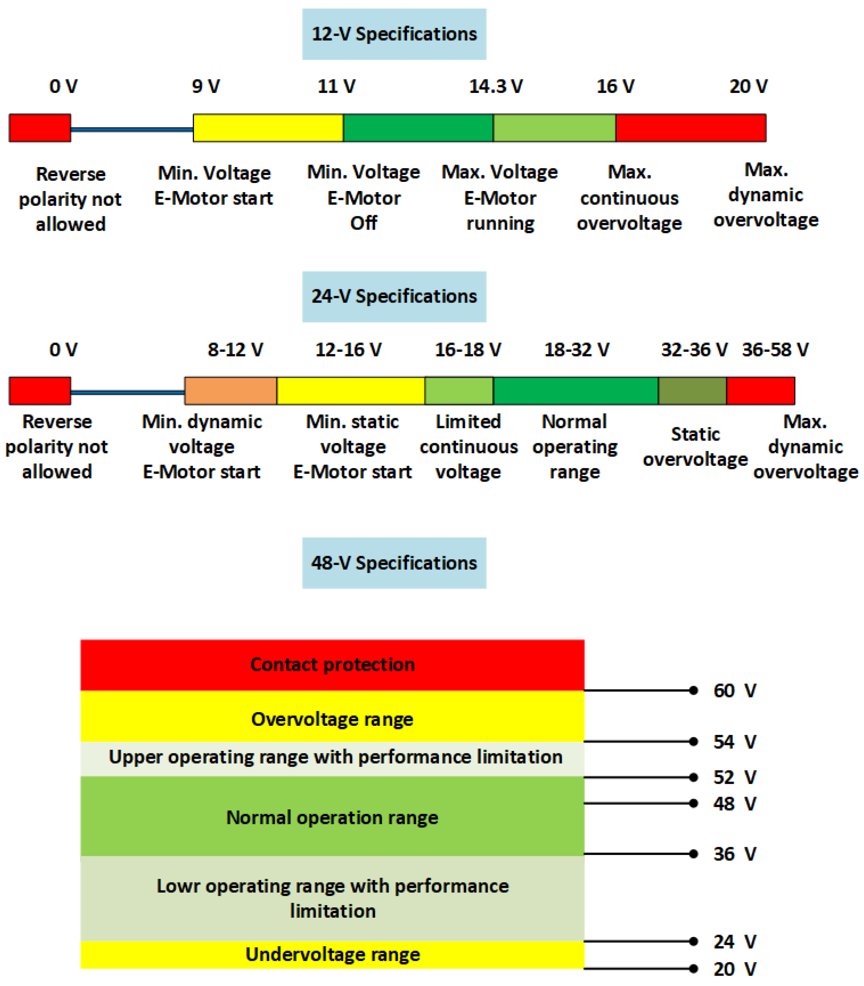
2.3. Electrical Requirements

The electrical requirements of an APM are defined based on standards LV-124/148. The standard represents several tests that subject the EV’s LV electrical control units (ECUs) to electrical disturbances, emulating them in a real EV. These two standards were put together by different German OEMs, such as Daimler, VW, and BMW [31,32,33].
The LV 124/148 standards define the minimum, maximum, and rated voltage specifications for an APM normal operation. In addition, the standard defines the allowed overvoltage on the LV rails during load dump scenarios. Figure 5 shows the different voltage specifications according to [28]. The voltage operating range of each LV network must be controlled by the APM’s low-level controller. In addition, the HW design of the APM has to take into consideration the LV-124/148 test scenarios. For instance, the APM HW design should ensure protection against the LV battery reverse polarity during vehicle maintenance or connection errors [34].

2.4. Efficiency Requirements

Maximizing the efficiency of the APM is a vital design requirement. The selected power semiconductors, passive and EMC filter components, as well as the control strategy are the main key factors in improving the efficiency of the APM system. The selection of the switching semiconductor material affects the volume and losses of the power converter [3,15]. Therefore, WBG semiconductor materials are seen as the future of automotive power converters.
AEC-Q101 is the common automotive standard for power semiconductor testing in terms of the life cycle, operating temperature, and working under vehicle vibration stresses [36,37,38]. According to AEC-Q101, SiC and GaN are the most adequate WBG materials for automotive applications [15,39]. In addition, the larger valence band of the WBG material results in fewer carrier concentrations. As a result, this increases the maximum allowable junction temperature [15]. Furthermore, their high thermal conductivity makes them a better choice for high-power-density applications with limited cooling resources [40,41].
Figure 6 summarizes the comparison between silicon (Si), SiC, and GaN semiconductor materials [15]. It is worth noting that GaN materials are characterized by higher electron mobility than SiC material, which gives them an advantage when operating at high switching frequencies than SiC [42,43]. However, SiC material shows less thermal resistance than GaN material, which makes it more suitable for high-power-density applications [39,44]. Table 2 summarizes a comparison between SiC and GaN, which was done for a 7.2 kW onboard charger (OBC) application [45].
Moreover, as the APM power level increases and the magnitudes of the current and voltage increase, the hard switching of the APM switches deteriorate the converter efficiency. Figure 7 shows the different switching behaviors of a SiC MOSFET transistor [46].   V G S is the gate-driver voltage, I D is the switch current, and V D S is the switch voltage.
The soft switching of a transistor is achieved either by ensuring zero voltage on the switch during the turn-on instant, as shown in Figure 7b, or by providing zero current in the switch during the turn-off instant (Figure 7c). Zero voltage switching (ZVS), and zero current switching (ZCS) are achieved by creating resonance between the switching device and the L or C elements around the semiconductor device during the turn-on and turn-off periods [47,48].
In [49], a comprehensive analysis of the ZVS and ZCS soft switching techniques in power converters is done. This study concluded that using the ZVS technique in high switching frequency applications is more beneficial. Otherwise, optimum switching behavior would be achieved using both ZVS and ZCS (ZVZCS).

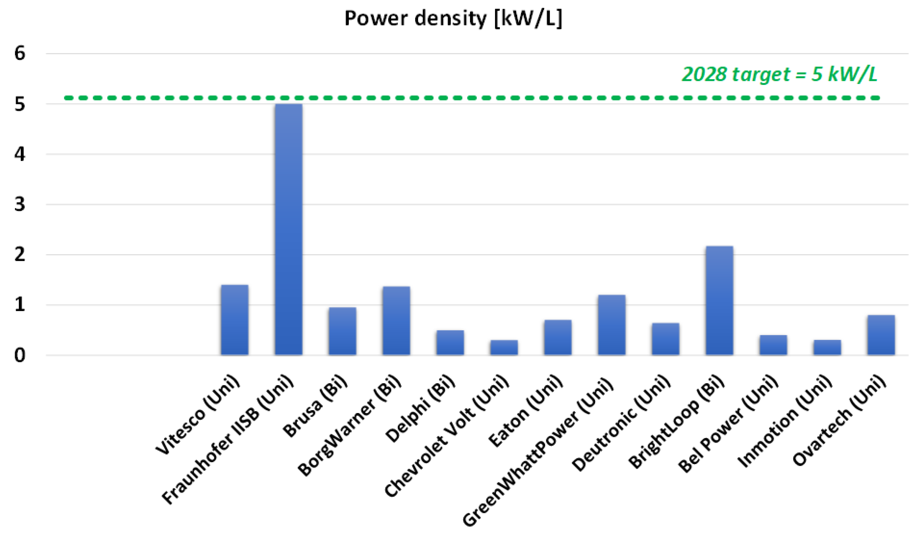
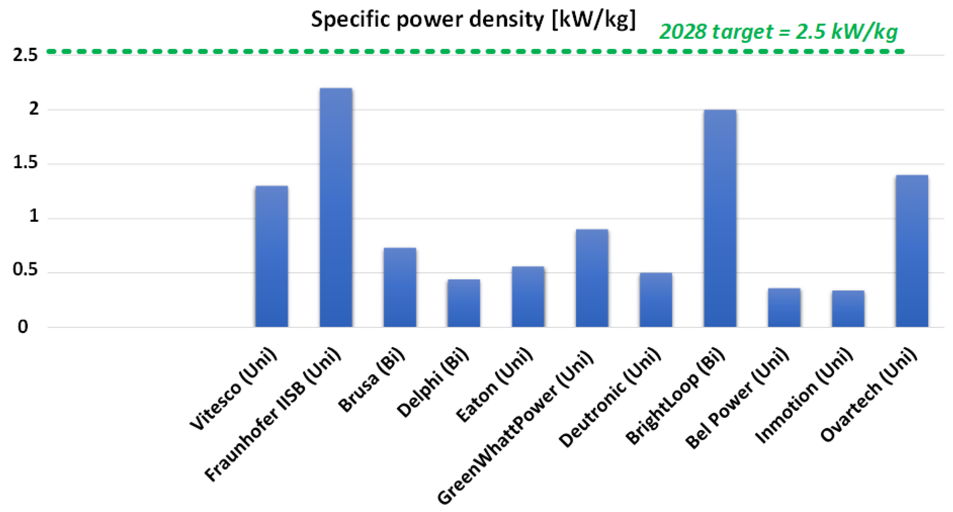
2.5. Power Density Requirements

The power density of a DC-DC power converter is defined as the amount of power that can be processed for a given volume unit (kW/ dm 3 ). On the other hand, the specific power density is defined as the ratio between the output power and the converter weight (kW/kg) [50]. To design a high-power-density APM, the DC-DC converter switching frequency shall be chosen high enough to reduce the passive elements’ size and weight [50,51,52]. However, the selection of the switching frequency is limited by the semiconductor switching capabilities and the cooling resources of the APM system.
According to [50], increasing the switching frequency of an isolated DC-DC converter from 100 kHz to 300 kHz will increase the power density from 25 to 28 kW/ dm 3 . In addition, using a water-cooled DC-DC converter instead of an air-cooled one would increase the power density at high switching frequencies of 1 MHZ from 40 to 60 kW/ dm 3 .
As will be seen in Section 6, the average power density of the APM systems from 13 companies was 1.2 kW/L. Nevertheless, some designs showed a very high power density, such as the Fraunhofer 5 kW/L multiport APM system [17]. On the other hand, the average specific power density of 11 companies was 1 kW/kg. Furthermore, the highest observed specific power density was 2.2 kW/kg from the Fraunhofer Research Center [17].
To conclude, Table 3 summarizes the main requirements of the APM according to the literature.

3. APM State-of-the-Art Topologies

The APM in an EV could be either a standalone system or a secondary auxiliary output from the onboard charger (OBC) system [14,58,62]. However, when the APM power rating is 6 kW or higher, having the OBC and the APM in one system will result in high cost, complexity, and lower reliability [63].
In this section, different single-input-single-output (SISO) and single-input-multiple-output (SIMO) isolated DC-DC converter topologies for an APM are reviewed. Figure 8 shows the different architectures of the SISO- and SIMO-isolated DC-DC converters. The simplest architecture for a SISO APM is to utilize a single isolating transformer with HV-LV stepping-down ratio, as shown in Figure 8a [63,64,65,66,67,68,69]. For SIMO architecture, the first solution according to the literature is to use a single-stage three-winding transformer with two output terminals, as shown in Figure 6b [58,62]. The second solution for a SIMO APM is by using two cascaded stages, as shown in Figure 6c. The second stage could be implemented as a non-isolated stage to convert the 48 V intermediate voltage to 12 V. This reduces the weight and cost of the system [70,71].
In the literature, isolated DC-DC converter topologies have been classified in different ways [25,72,73]. In this paper, the isolated HV-LV DC-DC converter topologies have been reviewed and categorized according to their capability to control the power flow either as a unidirectional or a bidirectional converter for EV applications. Figure 9 demonstrates an overview of the isolated HV-LV DC-DC converter topologies covered in this paper. However, most unidirectional converter topologies can be converted to bidirectional topology by replacing the output diode-based rectification stage with switches-based synchronous rectifiers, which improves the system efficiency with the tradeoff of cost and control complexity [68]. Nevertheless, in this section, the authors evaluate the topologies according to their efficiency, power density, the complexity of the control, and the number of switching elements in the topology.

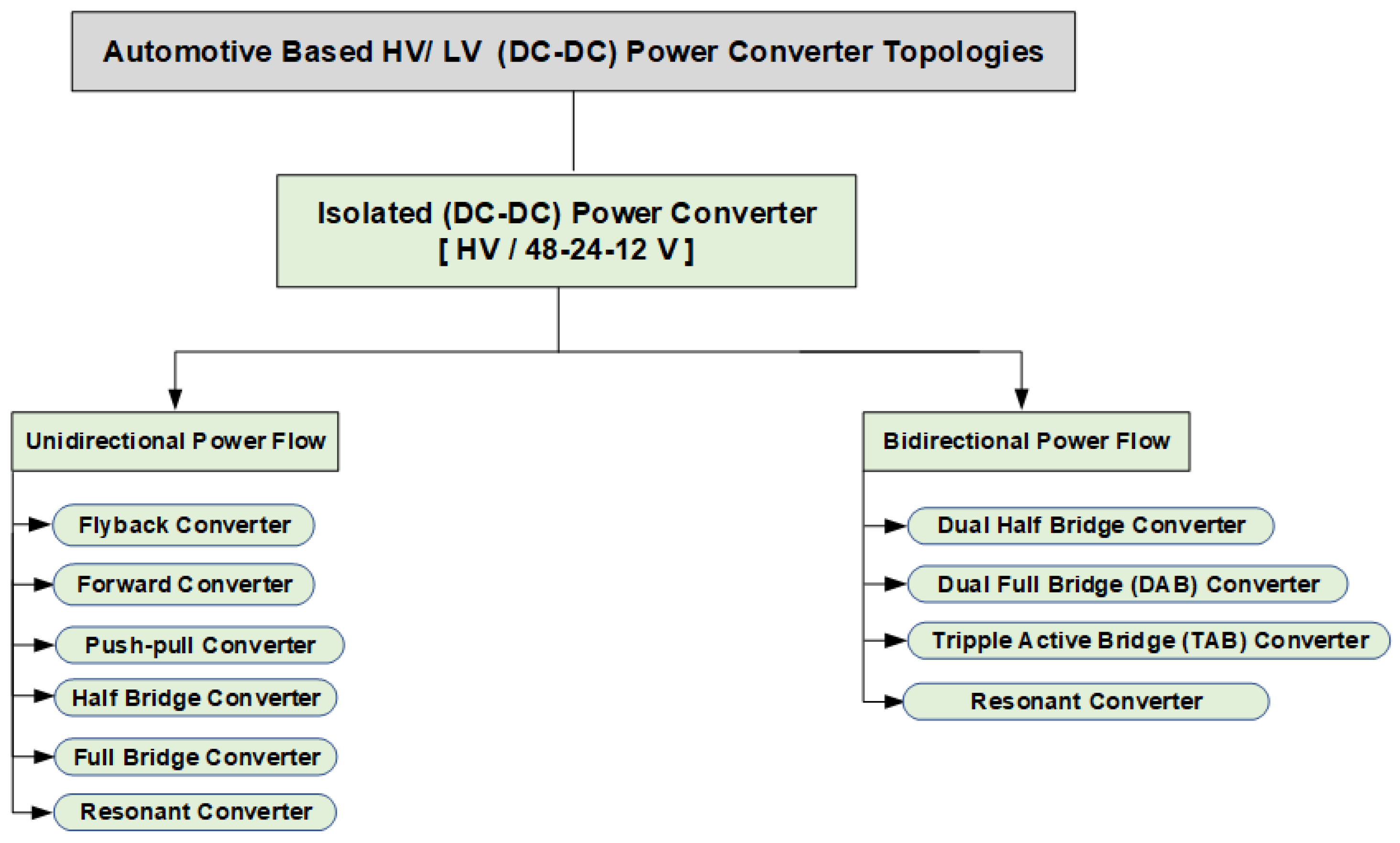
3.1. Unidirectional HV-LV Isolated DC-DC Converters

A unidirectional switched mode isolated DC-DC converter topology has to include the following [74]:
  • a transformer for galvanic isolation
  • a switching element on the HV battery side to control the power flow and output voltage
  • a passive rectification stage on the secondary side.
In this section, the most common unidirectional topologies have been reviewed.

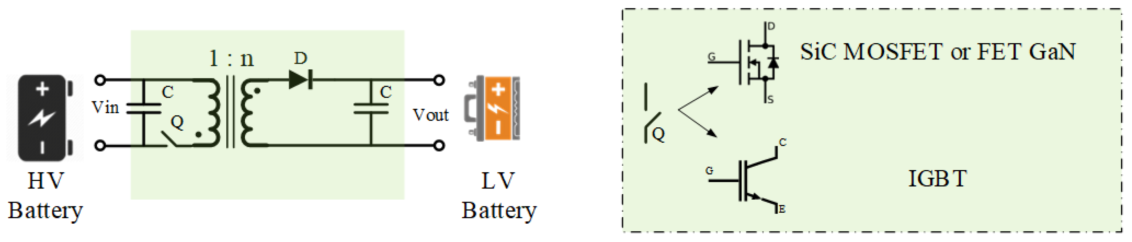
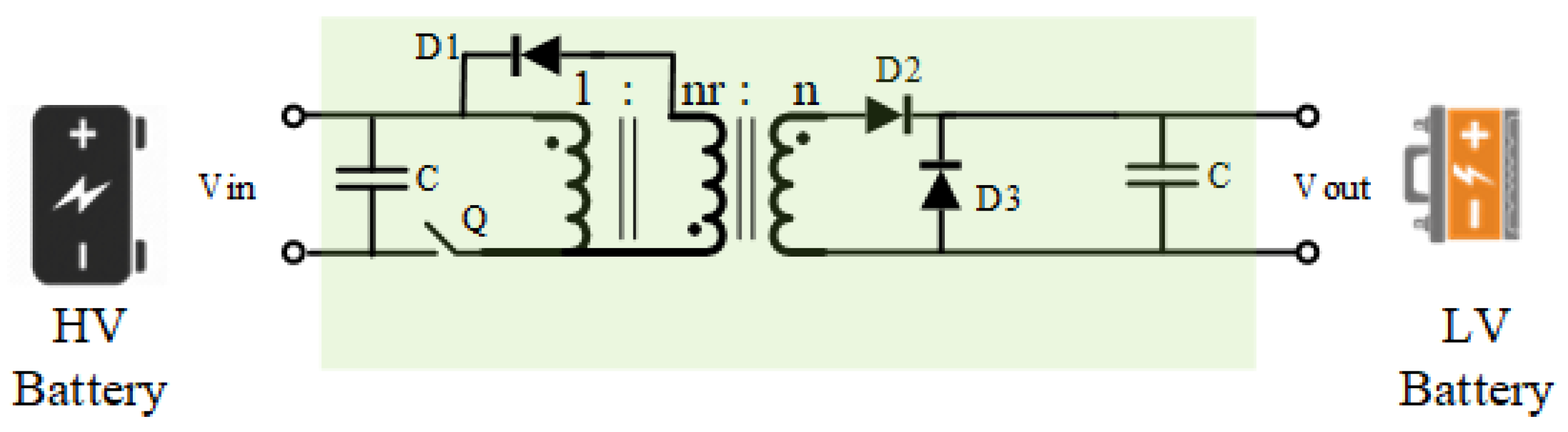
3.1.1. Flyback Converter

The flyback converter is one of the most frequently used topologies in the automotive industry due to its simplicity [63,72,74,75]. As seen in Figure 10, the converter is composed of one switch, one transformer, one rectifying diode, and two filter capacitors. It is mostly used for APM HV-12/24 V applications with low power ratings (200 W–1.5 kW) [63,64,76,77,78].
The biggest advantage of the flyback converter is that it can be extended from a single-stage SISO system to a single-stage SIMO system by simply introducing a secondary winding with a rectification stage [63,77].
In [63], a modular multiport APM converter based on flyback topology was proposed. In this study, cascaded flyback converters connected in series-input-parallel-output were used to reduce the stress on the LV terminal. However, it is stated that one of the disadvantages of the topology is the absence of natural balancing between the ports due to non-magnetic coupling between the core of the transformers. The main drawbacks of flyback converters are high stress on components for HV battery levels of 400–800 V [74], instability issues in the controller when operating in continuous conduction mode (CCM) [75], and the duty cycle must be limited to a minimum value that allows the demagnetization of the transformer core to avoid the saturation effect [75,79].

3.1.2. Forward Converter

The forward converter resolves the limited duty cycle constraint of the flyback converter by including a third tertiary winding and a diode in the topology, as shown in Figure 11.
During the off periods of the Q switch, the tertiary winding provides a path for demagnetizing the current through diode D1 and resetting it to zero [75,80]. As a drawback, this rotating current generates heat losses in the system. Similarly to the flyback converter, the forward converter is ideally used for HV-LV APM with a low power rating (maximum 200 W) [74]. In addition, it must operate at a maximum duty cycle of 50% to give time for the transformer demagnetization process [79].
In [65], a bidirectional hybrid topology was proposed with forward and flyback converters connected in series-input-parallel-output. The converter topology was tested on a 150 V–15 V APM application. The topology showed a poor efficiency of 90%. In addition, reverse power control from the LV side to the HV side can be done only if the HV bus is less than a specific value. Moreover, the main drawback of the forward converter topology is the huge leakage inductance of the three-winding transformer, which contributes to a high transient current while operating at a high switching frequency [81].

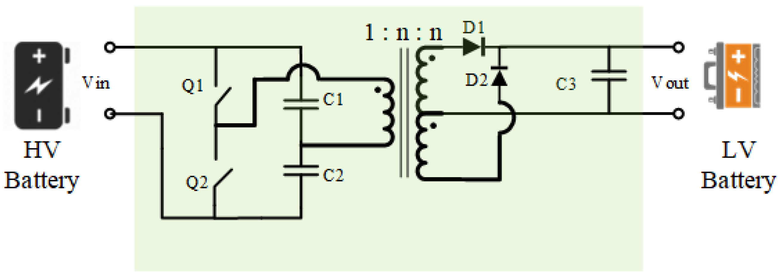
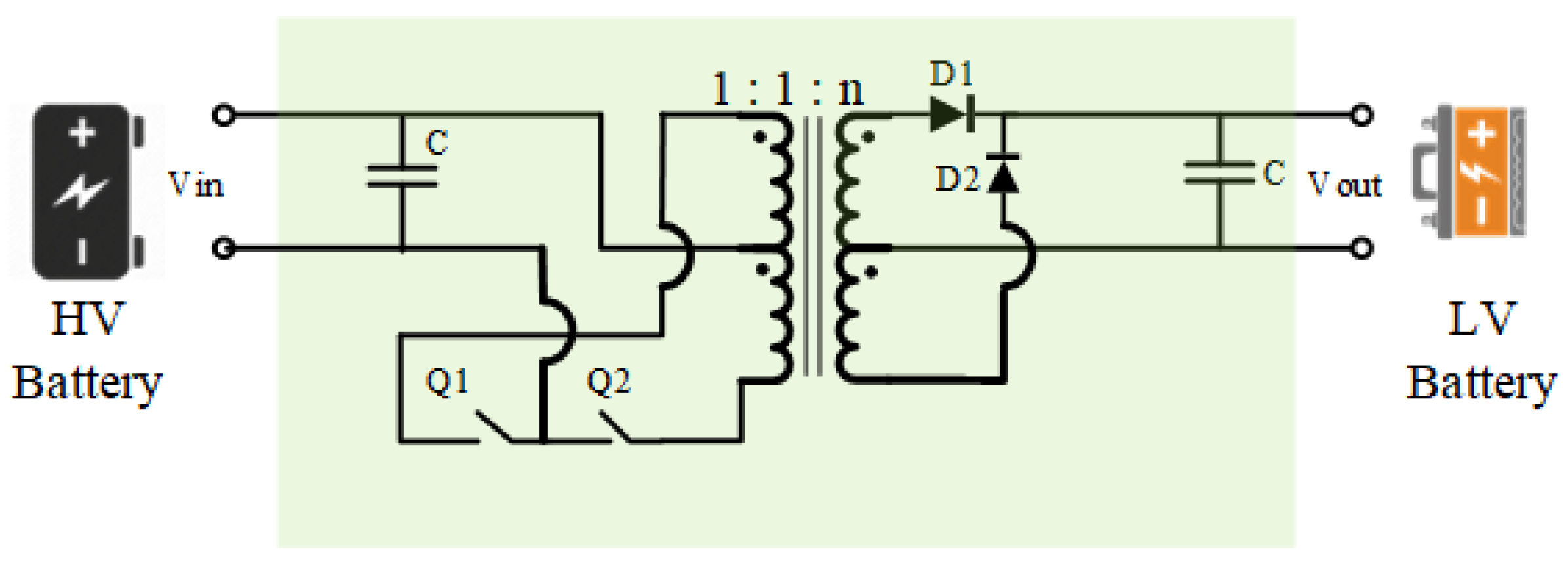
3.1.3. Push-Pull Converter

The push-pull converter is an evolution of the forward converter by replacing the demagnetizing tertiary coil and the diode with an inverter coil and a switch, as shown in Figure 12. The converter has two modes of operation (push and pull) [77]. During the push mode operation, switch Q1 is turned on, and the current flows from the HV battery side to the transformer winding, while during the pull mode operation, the switch Q2 is turned on, and the power flows from the transformer to the HV battery.
The transformer size of a push-pull converter can be smaller than forward and flyback converters for certain power levels because the transformer core is used in quadrants 1 and 3 of the BH-loop curve [79].
In [66], a 1 kW rated push-pull converter was designed for a 400 V–24 V APM application. One of the disadvantages of the push-pull converter is that the blocking voltage on each switch is 2 times the HV battery voltage. In [66], a snubber circuit was used to reduce the switching spikes on the switch, which decreased the overall efficiency of the converter. In addition, in [67], the performance of a 500 W push-pull APM is analyzed, which has been used in Toyota Prius cars for a 200 V–12 V APM application. To reduce the voltage stress on the switches, 4 IGBT switches on the primary side with a three-level topology were proposed. Nevertheless, the topology showed a poor efficiency of 90%. Figure 13 shows the proposed topology in [67].
To summarize, flyback, forward, and push-pull converter topologies are not favorable for APM applications with 800 V future EV voltage standards, as their high switching voltage stress could cause insulation problems, low efficiency, and instability of the controller.

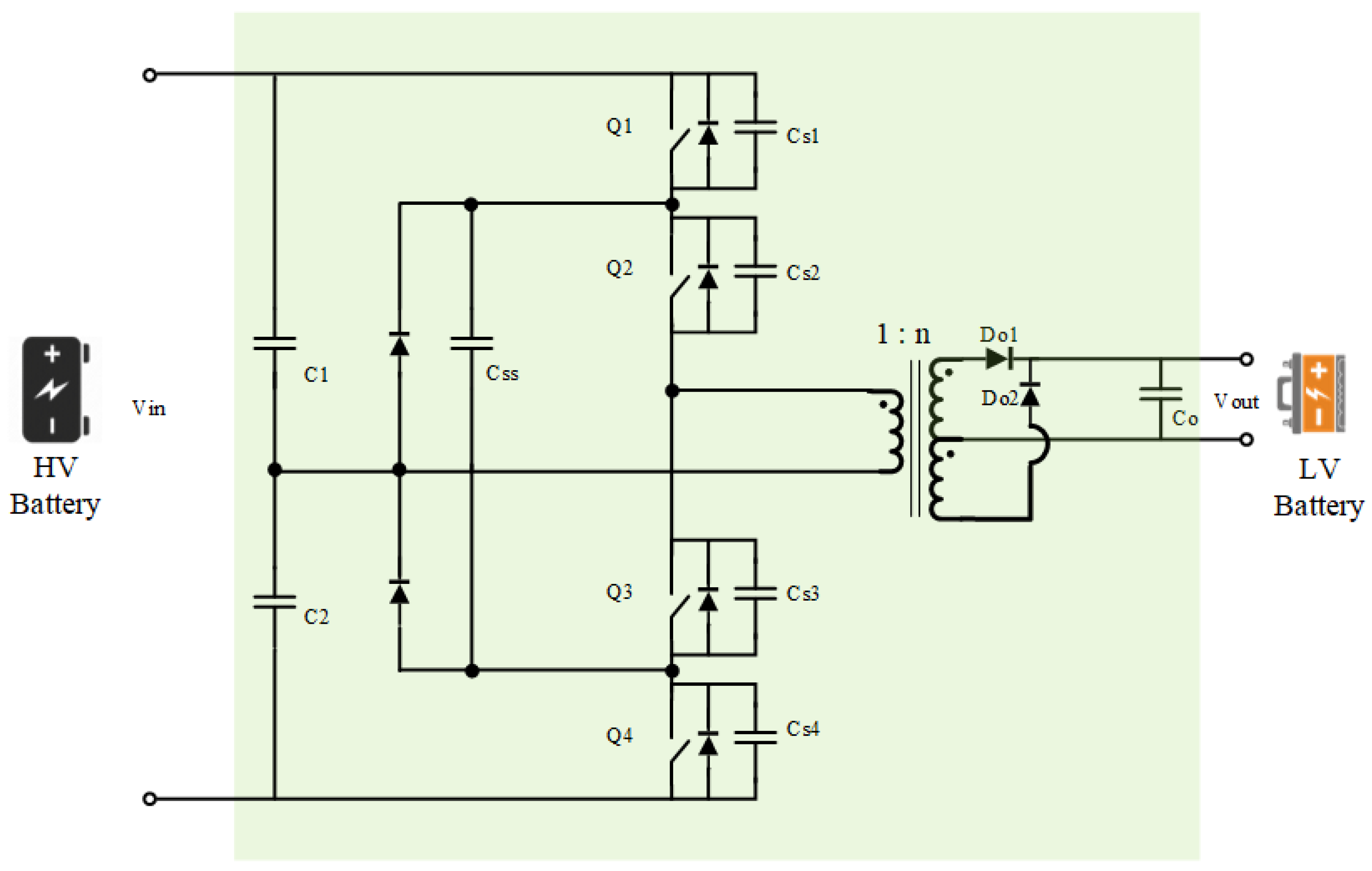
3.1.4. Half-Bridge Converter

The half-bridge converter uses two switches on the primary side of the isolating transformer, as shown in Figure 14. Two splitting capacitors are used on the primary side of the transformer, so the voltage across the primary side of the transformer is always half of the HV battery. These splitting capacitors limit the maximum blocking voltage of each switch to input HV ( V HV ) and not 2 × V HV . This gives an advantage to the half-bridge converter and allows it to be used for higher power ratings [77].
In [62], a SIMO converter was presented as an application of integrated OBC and APM in one system using a half-bridge topology. The APM was designed for the 400 V–12 V APM application, with a rated power of 500 W. The maximum efficiency of the converter was 94%. As mentioned earlier, the main disadvantage of integrated OBC and APM topology is the huge 3-winding transformer and capacitor ratings. In addition, the topology contains a high number of semiconductors, which adds complexity and cost to the control of the topology.
The main drawback of the half-bridge converter topology is the mismatch in the splitting capacitors due to manufacturer tolerance or environmental effects. As a result, the voltage across them will not be identical, and the current-control mode will worsen the voltage imbalance, eventually causing one capacitor to discharge to zero and stopping the converter [79,82]. In addition, the half-bridge converter has low efficiency due to the high conduction losses.

3.1.5. Full-Bridge Converter

The full-bridge converter is the most favorable topology for high power rating DC-DC converters with high power density [83]. The converter topology, as shown in Figure 15, reduces the current stress in the switches to half in comparison to the half-bridge topology. In addition, it can easily be operated at high switching frequency while employing the soft switching ZVS technique via the phase shift modulation technique [48,84,85].
Generally, the main advantage of the phase-shift full-bridge (PSFB) converter topology is its ability to control the converter output voltage by controlling the phase shift between the two converter legs. In addition, parasitic capacitors are used to facilitate the resonance transition of power between the transformer primary and secondary while approving soft switching [48,84,85].
In [86], a full-bridge APM was designed for a 400 V–48 V application with a high-power density (9 kW/L). Furthermore, in [69], another APM was proposed based on PSFB topology for 400 V–12 V application. The converter was rated at 2 kW with a maximum efficiency of 95%.

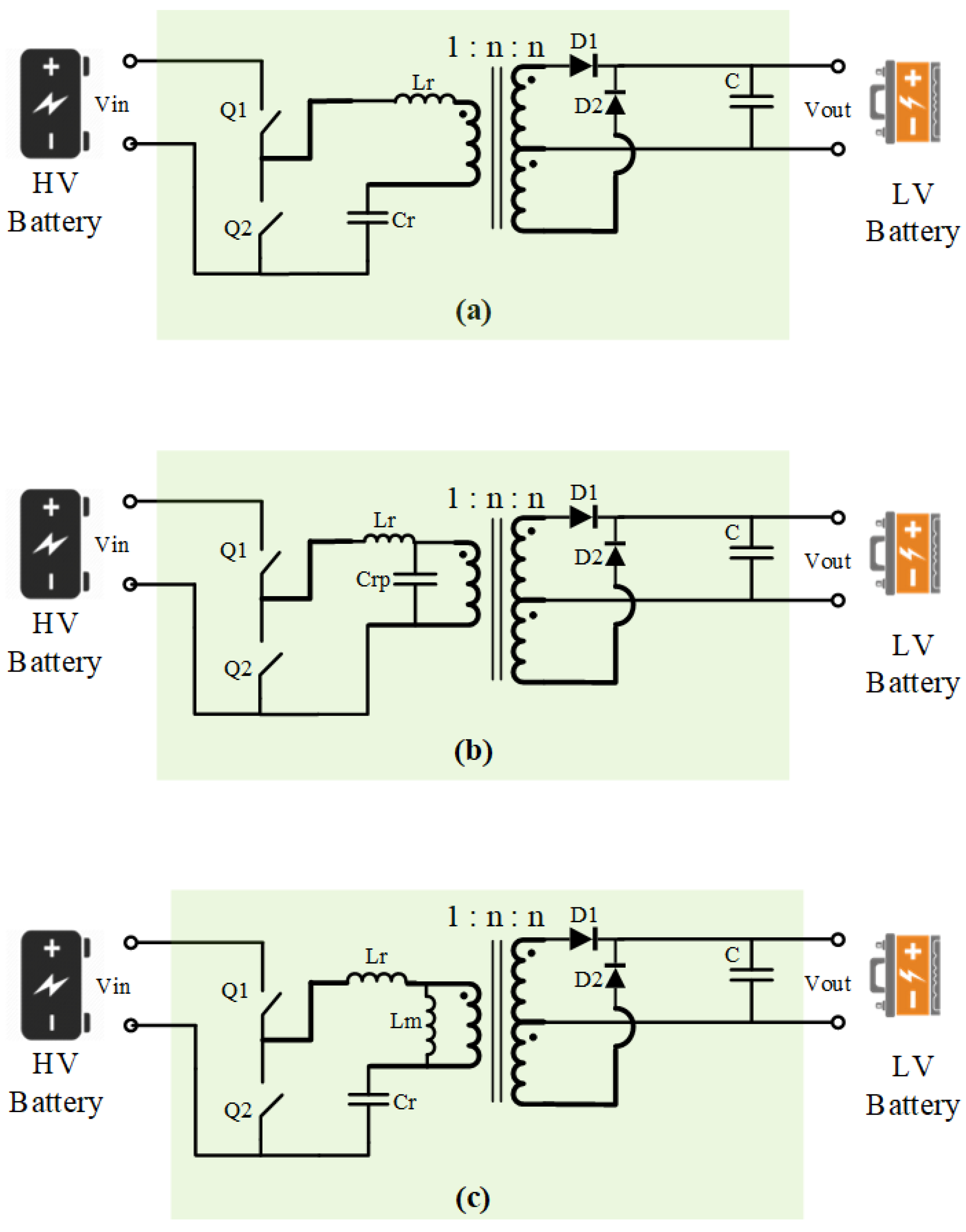
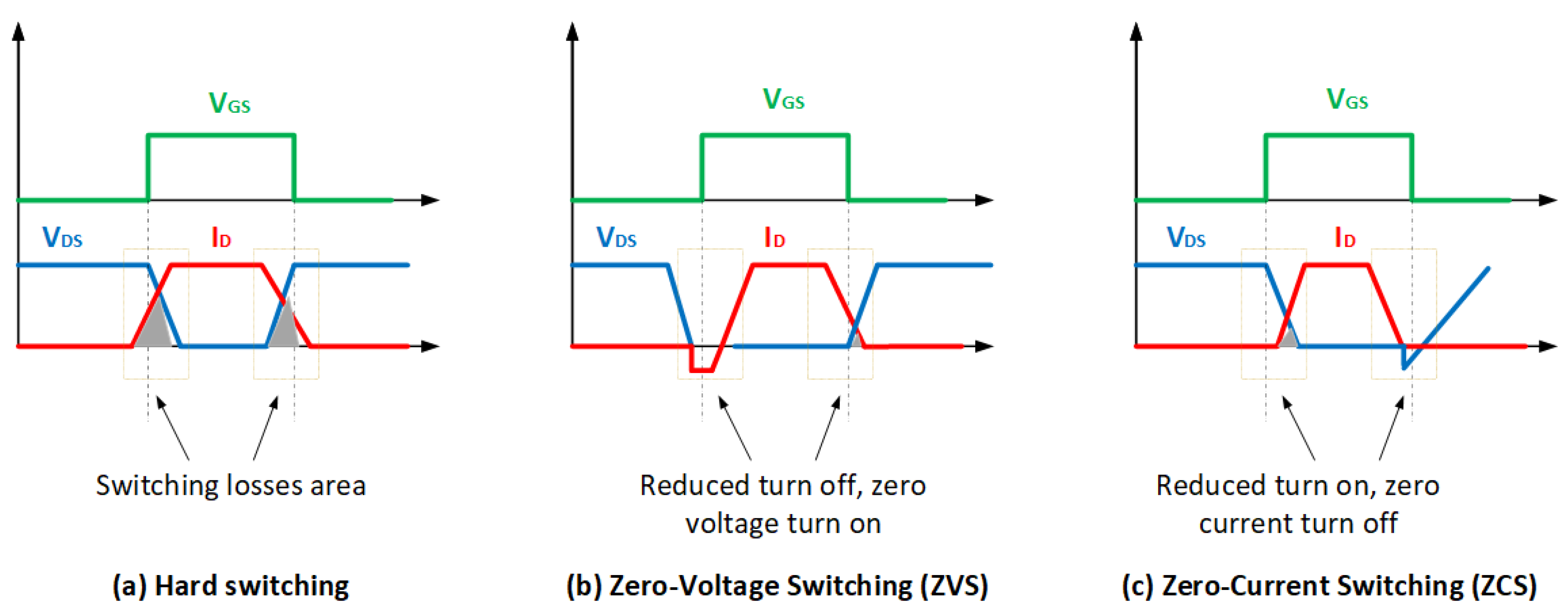
3.1.6. Resonant Converters

A resonant unidirectional isolated DC-DC converter is a conventional isolated converter with added capacitive elements either in series (series resonant converter (SRC)) or in parallel (parallel resonant converter (PRC)) to the transformer’s primary side winding. This series/parallel connection between the transformer leakage inductance and the added capacitors is called the LC resonant tank [87]. Furthermore, a multi-resonance converter is a converter with more than two resonant elements, e.g., in the case of including the transformer’s primary magnetizing inductance in the resonant tank design (LLC resonant converter) [88,89,90].
Unlike the previously discussed phase shift-controlled converters, where the voltage transfer ratio is controlled either by the duty cycle of the switch or by the phase shift between the two legs of a full-bridge converter, resonant converters depend on frequency modulation (FM). This makes the control design of such converters complex compared to phase shift-controlled converters [89]. Figure 16 shows a resonant half-bridge isolated DC-DC converter with three different resonant tank configurations. Lr, Cr, and Crp are the resonant tank elements.
The main advantage of a resonant converter is that it can easily achieve high efficiency by working at the resonance frequency and approving a wide-range soft switching operation [90]. ZVS and ZCS are achieved by creating resonance between the switching device and the resonant tank during the turn-on and turn-off instants.
According to [87], SRC and PRC converters have two main drawbacks. Firstly, SRC requires a wide range of frequency variations to regulate the output voltage. Secondly, PRC suffers from low efficiency and high circulating current at light load conditions. Therefore, he proposed that multi-resonant converters, such as LLC converters, can overcome such limitations.
In [91], a 3.8 kW LLC unidirectional APM was proposed for 400–14 V application. This can be interpreted as 270 A at 14 V rail. To achieve such a high ampere rating, the author proposed a SISO converter with three-interleaved LLC converters connected in a parallel-input-parallel-output connection. In addition, the author used a full-bridge instead of a half-bridge on the primary side to reduce the voltage stress on switches. The topology showed an efficiency of 96.5% by using the ZVS technique. In addition, the power density was 3 kW/L. However, the topology suffered from a very high number of switching elements (30 switches) and 6 transformers, which adds a huge burden on the cost and the complexity of the control algorithm.

3.2. Bidirectional HV-LV Isolated Power Converters

As mentioned previously, bidirectional power flow functionality is an essential requirement for an APM in modern BEVs. This section reviews bidirectional power-controlled APM topologies.

3.2.1. Dual Half-Bridge (DHB) Converter

As shown in Figure 17, the DHB converter is a modified version of the half-bridge converter topology that replaces the uncontrolled rectification stage with synchronous rectifiers. Using the transformer primary winding’s leakage inductance (Lk), bidirectional power control is achieved by introducing a time delay between the PWM signal of the primary half-bridge and the second half-bridge. This time delay is known in control theory as phase shift bidirectional power flow control [56,92]. This control technique will be discussed in more detail in Section 5.
The converter is recommended to operate a constant duty cycle of 0.5 for each H-Bridge, and the voltage ratio is adjusted by the transformer primary to secondary turns ratio for HV-LV conversion [56].
In [55], the author studied the phase shift control techniques of a 290 V–18 V APM to increase the ZVS range of a DHB converter and improve its efficiency. The converter operation was analyzed under different loading conditions. At the end, an optimum phase shift operating strategy was developed under different loading conditions and achieved a maximum converter efficiency of 97%. On the other hand, the author mentioned that one of the drawbacks of the DHB topology is that the splitting capacitors must carry all the transformer current, which results in a bulky capacitor design. In addition, in the case of higher HV battery voltages, the voltage stress on the switches will be high enough to cause a breakdown in the case of voltage overshoots.

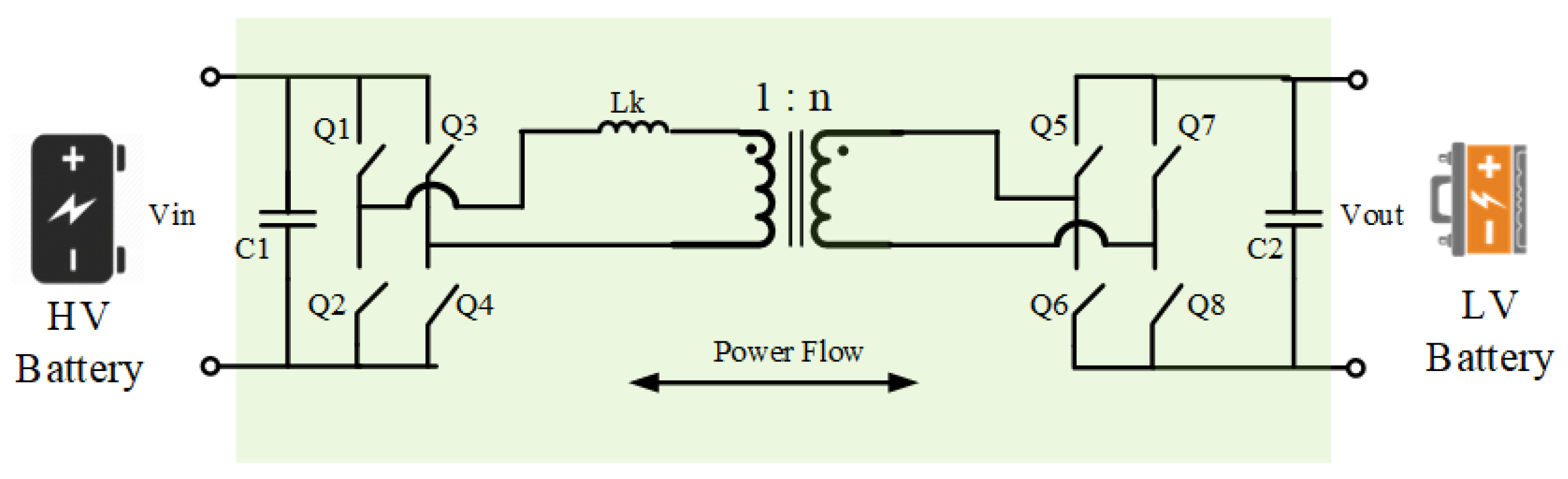
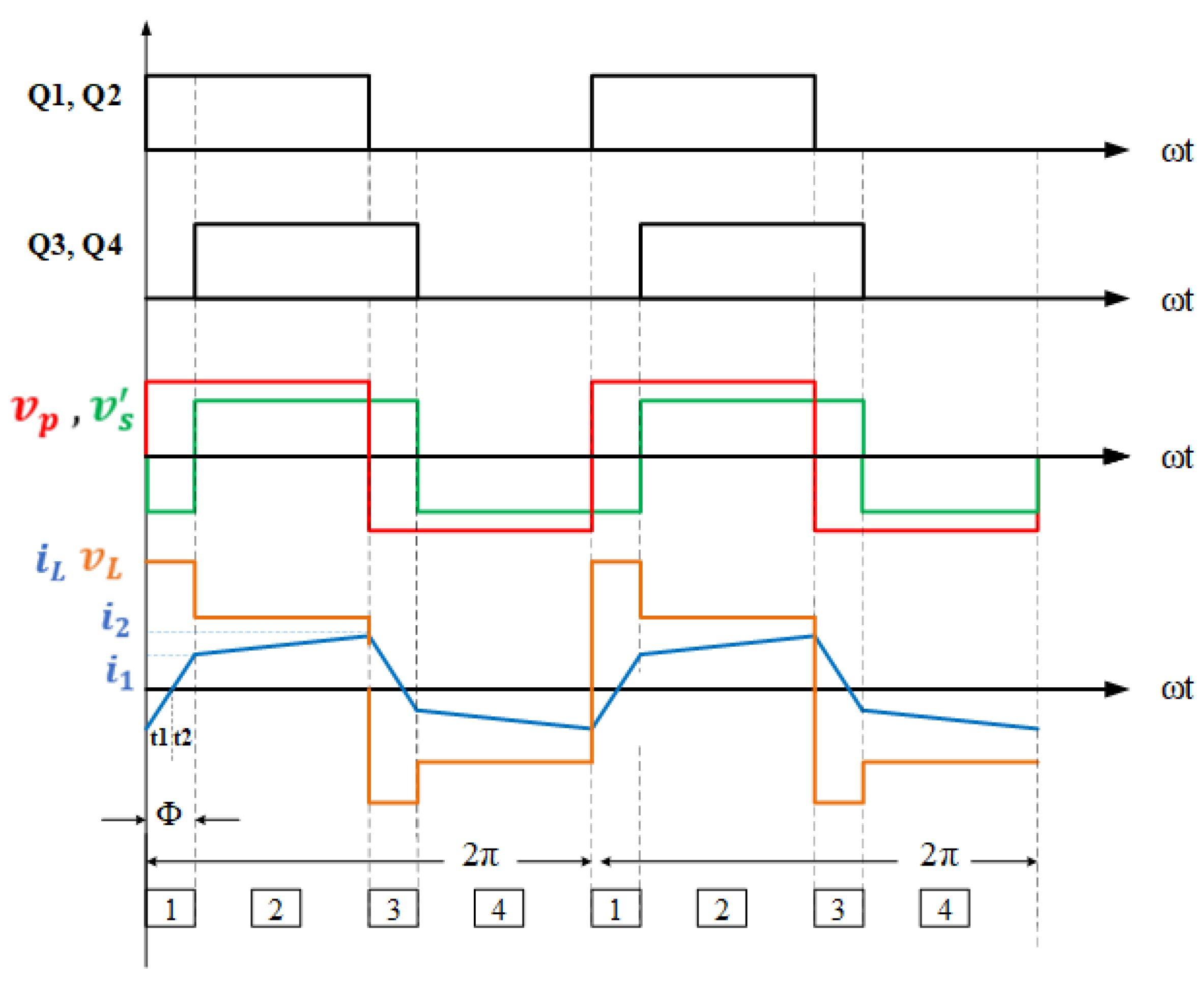
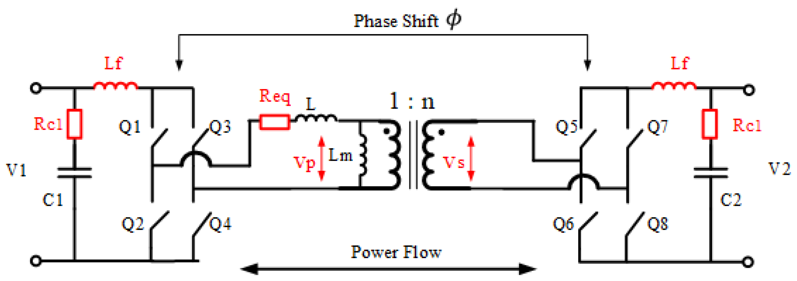
3.2.2. Dual Active Bridge (DAB) Converter

The DAB converter topology shows many advantages over the DHB converter and resonant converters. By comparing different topologies, the DAB converter offers bidirectional power flow with simple architecture, high efficiency, and high power density [56]. Using the same control concept as the DHB converter, bidirectional power flow control is provided by controlling the phase shift angle between the primary and secondary full bridges, as shown in Figure 18.
In [93], a 2.4 kW APM was presented for a 400 V–12 V application. The APM was integrated with the EV’s OBC. The APM was used as an active filter during the HV battery charging mode, which reduced the size of the OBC’s output filter capacitor. One of the disadvantages of the design was the limited ZVS range at the low loading conditions of the LV battery.
In [57], the DAB converter topology was compared to an LLC resonant converter topology for a 400 V–24 V APM application. In the end, the author concluded that the DAB converter could achieve a reduction in losses by 27% in comparison to the LLC resonant converter.

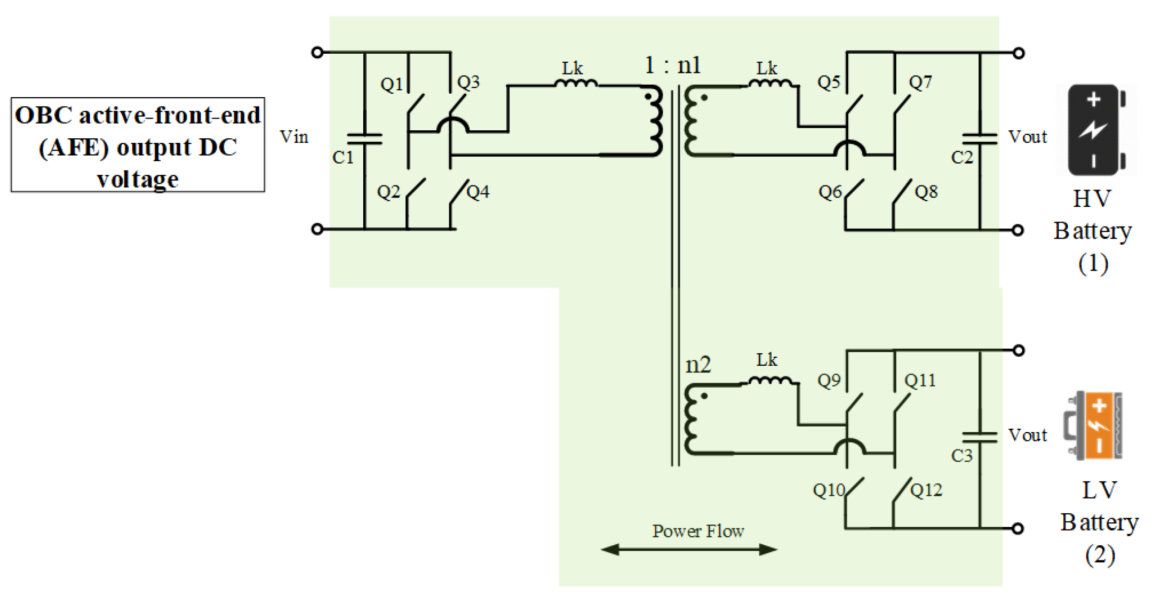
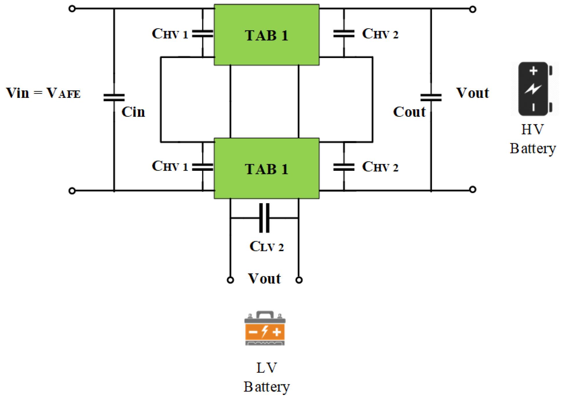
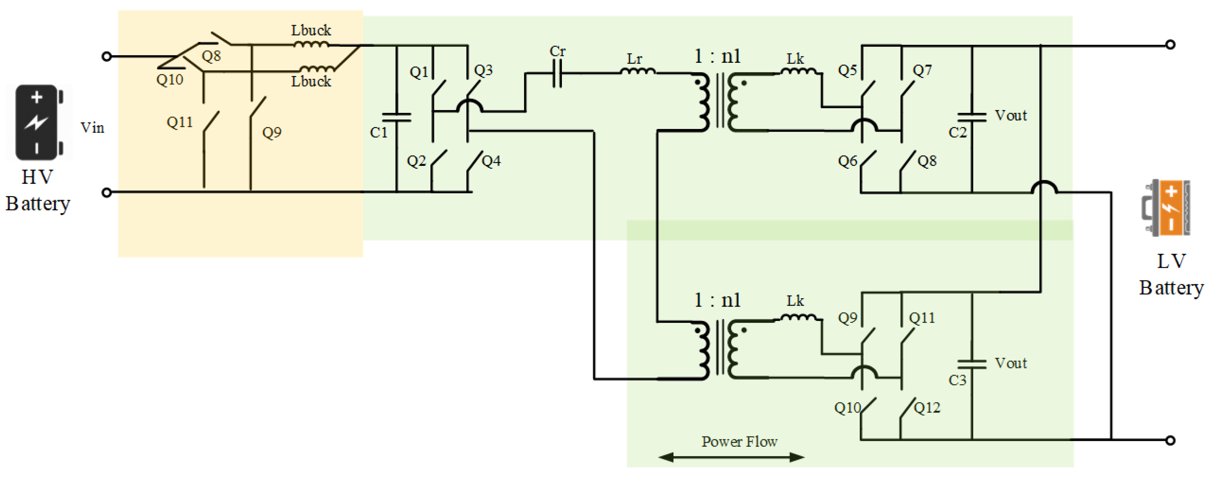
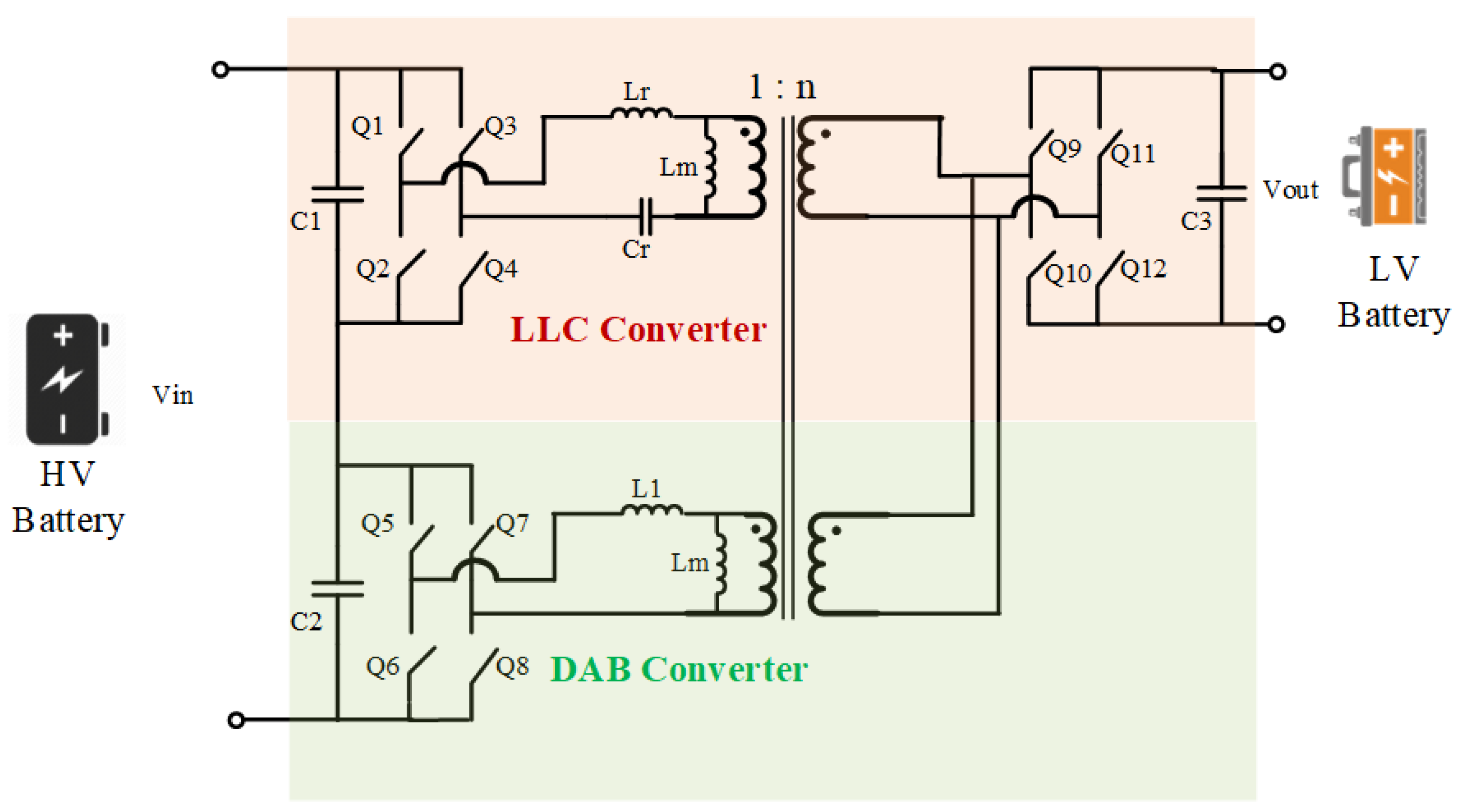
3.2.3. Triple Active Bridge (TAB) Converter

The triple active bridge (TAB) topology is a modified SIMO topology from the DAB converter using a three-winding transformer and a second H-bridge on the secondary side. The TAB converter is shown in Figure 19. The main advantage of this topology is that it provides a simple solution for multiple isolated outputs with a simple control.
In [58], a multiport/multi-cell (MPMC) DC-DC converter based on TAB converter topology was presented for the EV power distribution network. The converter can be used for both the APM and OBC-isolated DC-DC stages. Each cell of the TAB topology is shown in Figure 19. By connecting multiple cells in a series-input-parallel-output connection, the APM rating can be increased for high DC voltage and LV current, with minimized losses. Using this concept, the author proposed a 2 kW power rated 500 V–15 V APM design with two TAB cells.
Figure 20 shows the connection of the cells for the OBC + APM system [58]. The main disadvantage of the topology is that based on the predefined LV network impedance, and the high di/dt, it is required to have low parasitic inductance, which is hard to achieve in HW design.

3.2.4. Bidirectional Resonant Converter

A bidirectional resonant converter is like the DAB converter architecture with an added LLC or CLLC resonant tanks between the two full bridges [94,95,96,97,98]. Figure 21 demonstrates the LLC and CLLC resonant converter topologies. According to [97], the CLLC resonant converter has the advantage of a wider frequency modulation range than the LLC converter. In addition, bidirectional resonant converters have low EMI, high power density, and high efficiency [98,99].
Nevertheless, the bidirectional power control of a resonant converter is complex in controller modeling and requires large computation capability. In addition, the phase-shift-time-based control of an APM system with a wide ZVS range can achieve similar results to resonant converters with much simpler control algorithms [100].
In [95], a 1.65 kW APM design was presented based on LLC resonant converter topology. The converter achieved maximum efficiency of 97.6% with a wide output LV range from 17 V to 56 V. The study focused on developing an optimum modulation scheme for the LLC converter that approves high-efficiency operation. The main drawback of the topology is the high turn-off currents on the LV side.
In [101], a high-power (6 kW peak) APM was designed for a 400 V–12 V application. As shown in Figure 22, to achieve more than 500 A at 12 V rail, the author implemented a TAB converter topology with two separate transformer cores. The converter was composed of two cascaded systems. The first stage was an interleaved non-isolated buck converter to step down the HV battery voltage to an intermediate voltage. Then, a second stage of the LC resonance converter was implemented. The two transformers were connected in a series-input-parallel-output connection. The topology achieved a peak efficiency of 96%. However, the drawbacks of the topology were the high cost and the intermediate buck stage, requiring the extra controller to achieve ZVS.
In [102], the author presented a unique solution for an optimized low-power (80 W) 48 V–5 V APM application using the DAB converter topology with an LLC resonance converter, as shown in Figure 23. The two converters shared the same magnetic core as the transformer, which reduced the losses. The author implemented a hybrid control strategy for the converter in order to achieve ZVS at full load range at primary side switches, and ZCS at secondary side rectifiers. The gain of the LLC converter is controlled with the switching frequency to distribute the power among the LLC stage and the DAB stage. The converter operating frequency range was 320–400 kHz. The optimized hybrid controller showed maximum efficiency of 96% with minimized output voltage ripple.

3.3. Summary of SotA APM Topologies Review

The recent research effort focused on using DAB and TAB converter topologies. The topologies ensure simple bidirectional power flow control of the APM. In addition, LLC and CLLC resonant converter topologies have been investigated in some papers by using frequency modulation to control the converter’s gain. Furthermore, to ensure high power ratings at the LV rail, a non-isolated interleaved bidirectional converter can be used in cascade with the DAB, TAP, LLC, and CLLC converters.
The main disadvantages of the DAB and TAB converters are the limited ZVS range and the dependency of the ZVS operation on the load condition. On the other hand, the main disadvantage of the frequency-based control of resonance converters is the complexity of the control. Nevertheless, resonant converters can achieve high power density and high efficiency by ensuring ZVS and ZCS techniques. In [57], the DAB and LLC converter topologies were compared for a 400 V–20 V 330 W APM application. The authors measured the efficiency of the two topologies at a 1 MHz switching frequency. The conclusion was that the DAB converter could achieve higher efficiency than the LLC resonant converter by 27%. This is because the LLC converter peak current is constant at the complete LV load range. However, with the DAB topology, the transformer peak current is proportional to the load level.
Few pieces of literature have been published in academia for presenting the potentiality of multiport DC-DC converters for EVs’ APM. In [9], a full-bridge magnetically coupled multiport APM topology was proposed with two outputs of 48 V and 12 V. The control strategy of the converter was validated with a 2.5 kW rated lab prototype.
To conclude, Figure 24 demonstrates the proposed topology for a modular SIMO APM. Firstly, a DAB converter stage can be used for the HV-48 voltage conversion stage. Secondly, an interleaved non-isolated buck-boost converter can be used for the 48–12/24 voltage conversion stage. The second LV port’s voltage can be regulated by controlling the buck-boost stage duty ratio. Multiple buck-boost stages can be connected in a series-input-parallel-output connection to scale the 12/24 V rail power rating. SiC switches can be used in the HV-48 V stage due to the advantage of high breakdown voltage. GaN switches can be used in the non-isolated stage for 48 V–12 V conversion, as shown in the EPC company’s power conversion board [70]. The GaN switches will ensure a high switching frequency with minimized losses. Furthermore, the design ensures a wide input HV battery range. In the case of 400 V, the converter can be connected in a parallel input connection to reduce current stress. On the other hand, for the 800 V application, the converter can be connected in a series-input connection to reduce voltage stress on switches. The two transformer cores are isolated to isolate the disturbances and failures effect of one LV network on another.
Table 4 summarizes the topologies review section. In the next section, the control techniques of the APM systems are reviewed. The DAB converter topology will be used as the reference topology.

4. Control Techniques of an APM

The multiport APM system’s architecture is shown in Figure 25. The high-level software of an APM includes different layers. First, the low-level controller layer controls the power flow and voltage regulation on the APMs’ ports. Secondly, the thermal management layer is responsible for power losses and switches junction temperature estimation. Thirdly, the derating and protection layer monitors and controls the safety limits of the APM. Fourthly, the diagnostics layer. The APM is subjected to different stress factors, such as electrical, thermal, and mechanical stresses. These stresses would lead to early degradation of the system components, affecting the lifetime of the converter. Therefore, recent reliability studies recommend including a diagnostic module in the software of a DC-DC converter [103,104,105,106].
The derating and protection components override the requested load current in case one of the following derating functions is triggered:
  • Junction temperature derating: In cases where the estimated junction temperature exceeds the defined limit by the semiconductor manufacturers [107].
  • Overcurrent and overvoltage protection: According to LV124/148 standards, the APM shall be able to withstand overcurrent and overvoltage for a certain period. Otherwise, a counter-based derating function is triggered to disconnect the APM [28,90].
The LV lithium iron phosphate battery (LiFePO4) has been chosen as the reference LV battery type. The reason for choosing LiFePO4 over the lead-acid battery is because of the high-power density, energy storage capability, and greater number of cycles over the lifetime [108,109]. Figure 26 shows typical LiFePO4 battery state of charge (SOC) charts for 12 V, 24 V, and 48 V.
A tremendous amount of work has been done in the control techniques of phase-shift-based control converters [56,92,110,111,112,113]. In this paper, resonance converters were excluded. For this work, a brief discussion and comparative analysis of the most common low-level control techniques of a DAB converter are conducted. Firstly, Section 4.1 explains the control modes of an APM. Secondly, Section 4.2 reviews the different modeling methods of a DAB converter. Finally, Section 4.3 summarizes and compares the different control algorithms of a DAB converter.
Figure 26. LiFePO4 LV battery SOC charts (figure data from [114]).
Energies 16 01753 g026

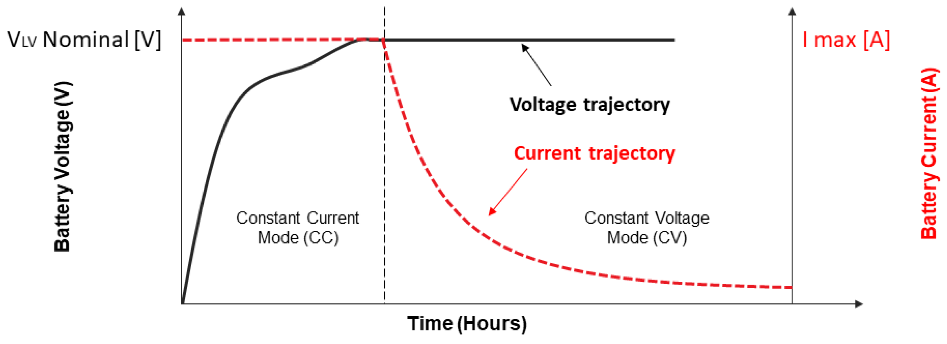
4.1. Control Modes of an APM

The two main control modes of a DAB-based APM are the constant current-control mode (CC) and the constant voltage control mode (CV) [13,115]. Figure 27 shows both control modes. CC mode is used during LV battery charging, where the charging current rate is controlled at a constant value. On the other hand, CV mode is used to control the APM output voltage at a constant value and to adapt with the connected network voltage according to the vehicle supervisory controller [13].
The APM low-level controller has a big impact on the system efficiency, the output port’s voltage/current ripples, and the transient response to sudden load changes and system disturbances. To design a robust and stable controller, the first step is to accurately model the APM. In Section 4.2, different modeling methods of a DAB topology-based converter have been reviewed.

4.2. DAB Converter Modeling Methods

Modeling is the mathematical representation of a physical system. Figure 28 shows the equivalent circuit of the DAB converter topology. Bidirectional power flow control is done by controlling the phase shift angle between the primary and secondary H-bridge PWM signals. The controlled power flow as a function of the phase shift angle ( ϕ ) is defined in Equation (1). For forward power transfer (HV-> LV) ϕ is positive. For backward (LV-> HV) power transfer, ϕ   is negative [56,111].
P = n V 1 V 2 2 π f s w L ϕ ( 1 ϕ π ) ,     n = N s N p ,     [ π 2   ϕ   π 2   ]      
where V 1 is input HV voltage, V 2 is output LV voltage, L is the transformer’s leakage inductance, n is the transformer turns ratio, and f s w is the DAB converter switching frequency.
Figure 29 demonstrates the key waveforms of a DAB converter using a single-phase shift (SPS) modulation scheme. The DAB converter operation is divided into four intervals according to the inductor current state. In this section, three different modeling methods of a DAB converter are summarized and compared. The modeling methods are demonstrated for the SPS modulation scheme. Nevertheless, these methods can also be used for double phase shift (DPS) and triple pulse phase shift (TPS) modulation schemes [112,117].

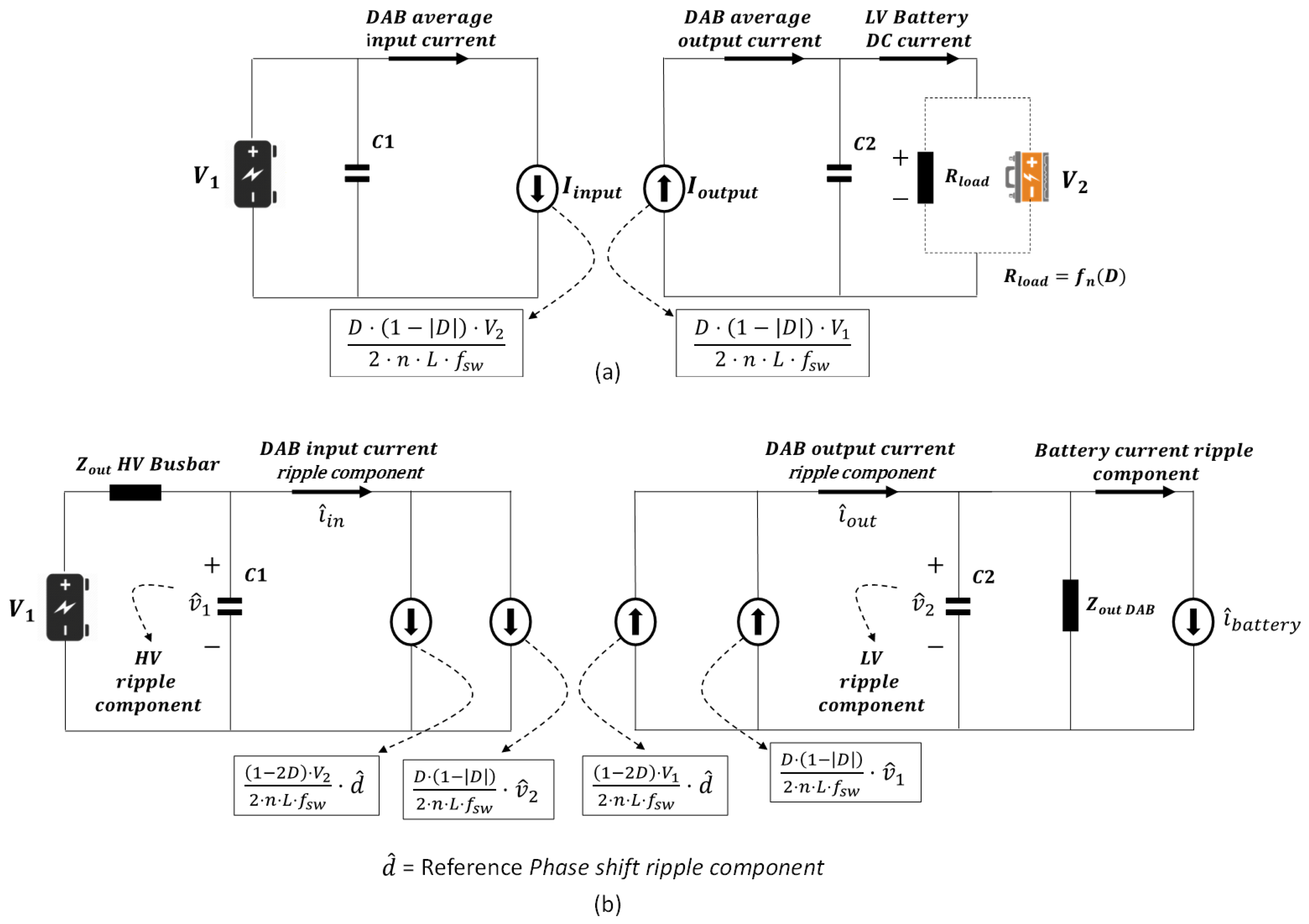
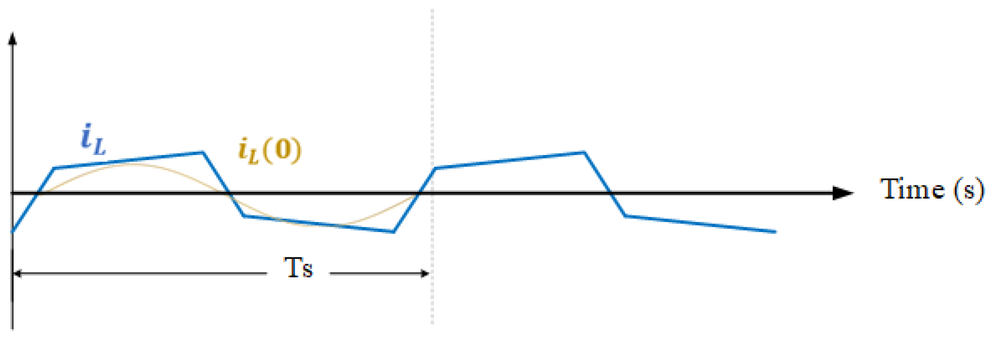
4.2.1. Reduced-Order Model

The reduced-order model eliminates the transformer AC component and its dynamics. This approximation will still lead to an accurate mode since the transformer dynamics are much faster than the DAB converter output DC voltage and current components. This modeling approach was adopted in [110,111,118]. The converter is characterized by the average value of both H-bridge currents over the switching period. Using the inductor voltage-second balance method over a half-switching cycle, one can estimate the steady-state value of the converter input and output currents as a function of the phase shift angle and the input/output DC voltages, as shown in Equations (2) and (3) [111]:
I b r 1 ( 0 ) = D ( 1 | D | )   V 2 2 n L f s w  
I b r 2 ( 0 ) = D ( 1 | D | ) V 1 2 n L f s w   ,                       D = ϕ π  
The block diagram of the DAB converter reduced-order model is shown in Figure 30. The phase shift angle ϕ is the output of the controller. Furthermore, the model accuracy could be increased by adding the parasitic elements of the input/output capacitors, the DAB equivalent resistance, and the filter inductors [116]. This is shown in Figure 31. The average model of the DAB converter can be perturbated in order to define the small-signal model, as shown in Figure 32 [111]. Z o u t represents the DAB converter’s equivalent output impedance with added parasitic elements and filter inductors.
The main drawback of the reduced-order model is that the transformer AC current is not observed. As a result, the transformer copper and core losses cannot be estimated. Therefore, the reduced-order model cannot be used for the efficiency analysis of the DAB converter.

4.2.2. Continuous-Time Full-Order Model

To observe the inductor current dynamics, the generalized averaging method could be used. The DAB converter states are represented by the Fourier series components. In this approach, the converter output DC voltage is represented by the k = 0 coefficient (average value) of the Fourier series. On the other hand, the inductor current is represented using the first harmonic approximation (k = ± 1), as shown in Figure 33. This approach was adopted by [112,119].
The Fourier series representation of the DAB converter state variables is shown in Equation (4) [116]. Then, the state-space representation of the DAB converter can be done as shown in Equations (5) and (6) [116]. Subscripts “(0)” and “(1)” refer to the average DC component and the fundamental frequency component. The state matrices A, B, and C of the DAB converter are shown in Equations (7)–(9).
x ( τ ) = x k ( t ) e j k ω s τ            
where ω s = 2 π f s w and the complex number x k ( t ) is the kth coefficient of the Fourier series.
d x ( τ ) d ( τ ) = A X ( τ ) + B U ( τ )   ,     X   = [ v ^ 2 ( 0 )     i ^ L R ( 1 )     i ^ L I ( 1 ) ]   ,     U = [ V 1 ]  
y ( τ ) = C X ( τ )   ,     y   = [ v ^ 2 ( 0 ) ]
A = [ 2 R L C 2 8 sin ( 2 π ϕ ) π C 2 8 cos ( 2 π ϕ ) π C 2 4 sin ( 2 π ϕ ) π L 2 R e q L 2 ω s 4 cos ( 2 π ϕ ) π L 2 ω s 2 R e q L ]                  
B = [ 8 C 2 ( I L I ( 1 ) sin ( 2 π ϕ ) I L R ( 1 ) cos ( 2 π ϕ ) 4 V 2 ( 0 ) sin ( 2 π ϕ ) L 4   V 2 ( 0 )   sin ( 2 π ϕ ) L ]                        
C = [ 1 0 0 ] T                    
The state-space equations can be used to drive a more accurate small-signal model of the DAB converter, which takes into consideration the transformer current transients. Furthermore, the phase shift to the output voltage transfer function can be estimated as shown in Equation (10) [116].
G ϕ v = C ( s I A ) 1 B                      
One of the drawbacks of the continuous-time full-order state-space model is the complexity of driving the model. In addition, as the full-order model accuracy highly depends on the first harmonic component, the model shows poor accuracy in the case of the presence of high harmonic distortion in the signals [120].

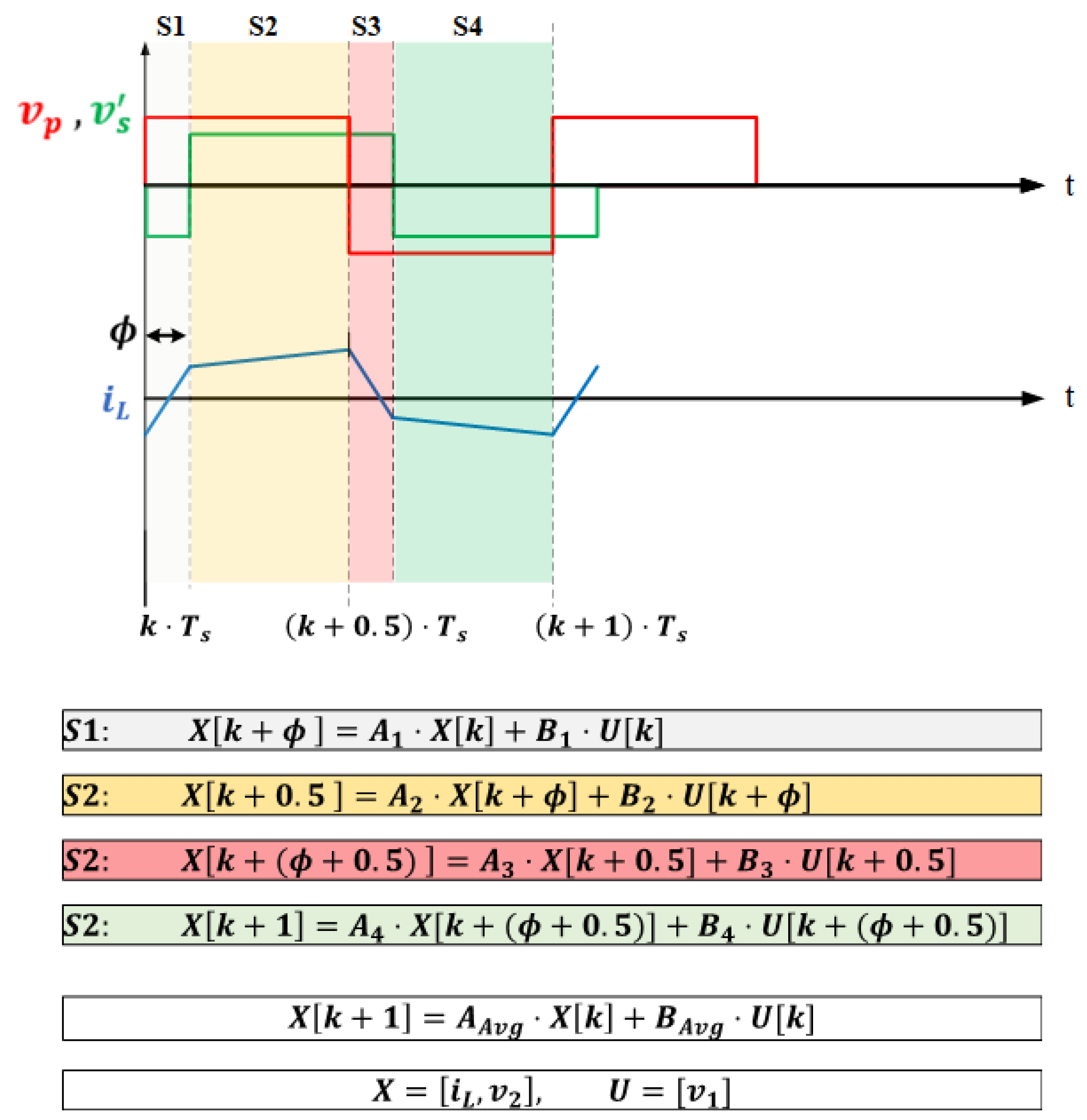
4.2.3. Discrete-Time Full-Order Model

The full-order state-space model can be represented in the discrete-time domain [121,122,123]. The main advantage of discrete-time modeling is that it is easier to implement on a high sampling rate digital signal processing (DSP) platform [123]. As shown in Figure 34, the DAB converter operation in one switching cycle can be divided into four switching states. The discrete-time model views the DAB converter state variables (e.g., i L and v 2 ) as they change 4 times in each switching cycle. The system state matrices are estimated once at each switching state. Then, the four state matrices are averaged over one switching cycle. Figure 33 shows the discrete-time modeling of a DAB converter.
Where ϕ is the phase shift angle, k is the sample number, [ A 1 4 ,   B 1 4 ] are the state matrices for the sub intervals, and [ A A v g ,   B A v g ] are the system average state matrices over one switching cycle.
In [123], a highly accurate small-signal model of a 2 kW APM for 450 V–12 V application was implemented using discrete-time full-order modeling. Furthermore, in [124], a simplified discrete-time state-space model has been driven for 400 V–48 V APM application. After neglecting the system dissipative elements, the author reduced the system state-space equations into two equations and estimated the system state-space matrices over a half-switching cycle. Despite this, the main drawback of discrete-time modeling is the complexity in estimating the state matrices.
In conclusion, Table 5 summarizes the advantages and disadvantages of different DAB modeling methods.

4.3. DAB Converter Control Techniques

Many DAB converter control techniques have been discussed in the literature [116,124,126,127,128]. In this section, the most used control algorithms, such as feedback control, feedforward plus feedback control, sliding mode control, and model-based predictive control, will be discussed.

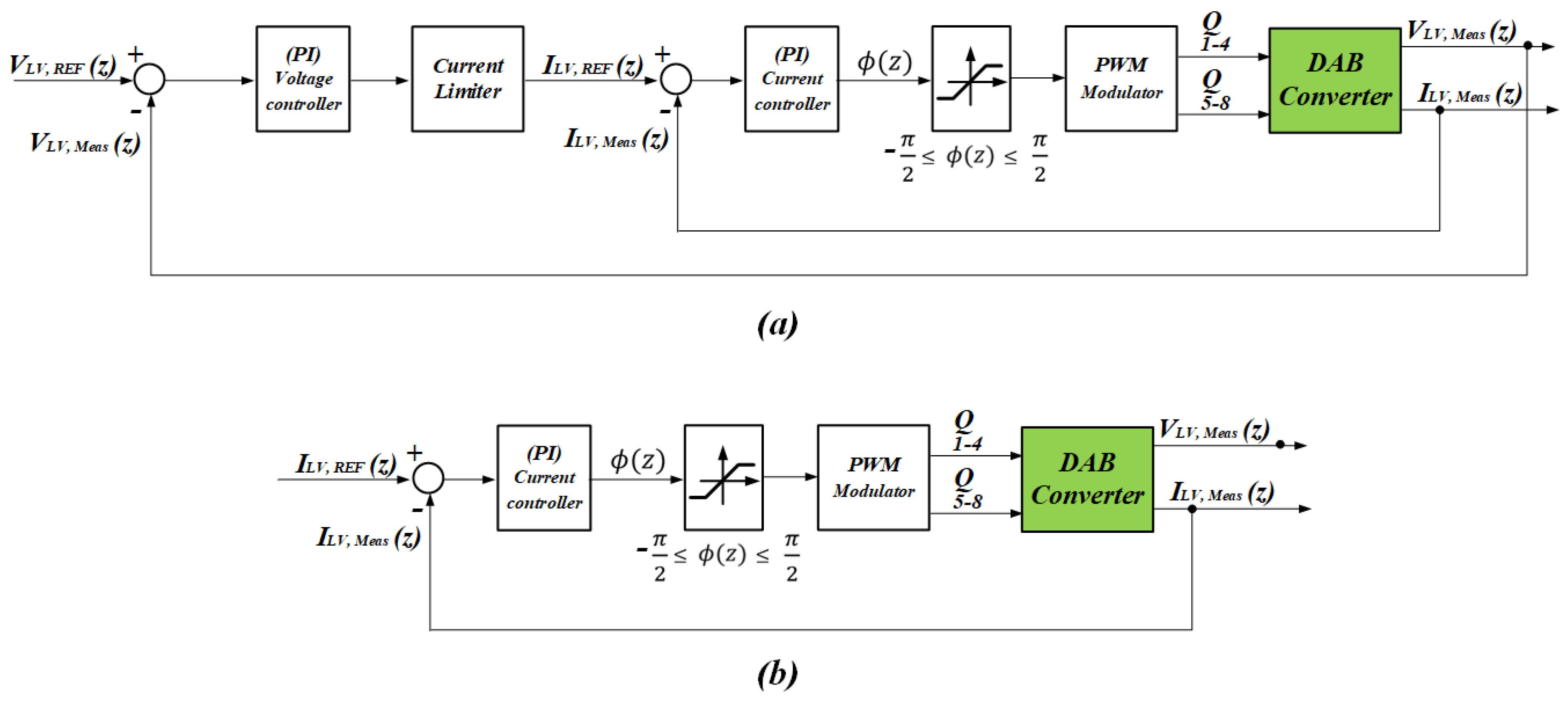
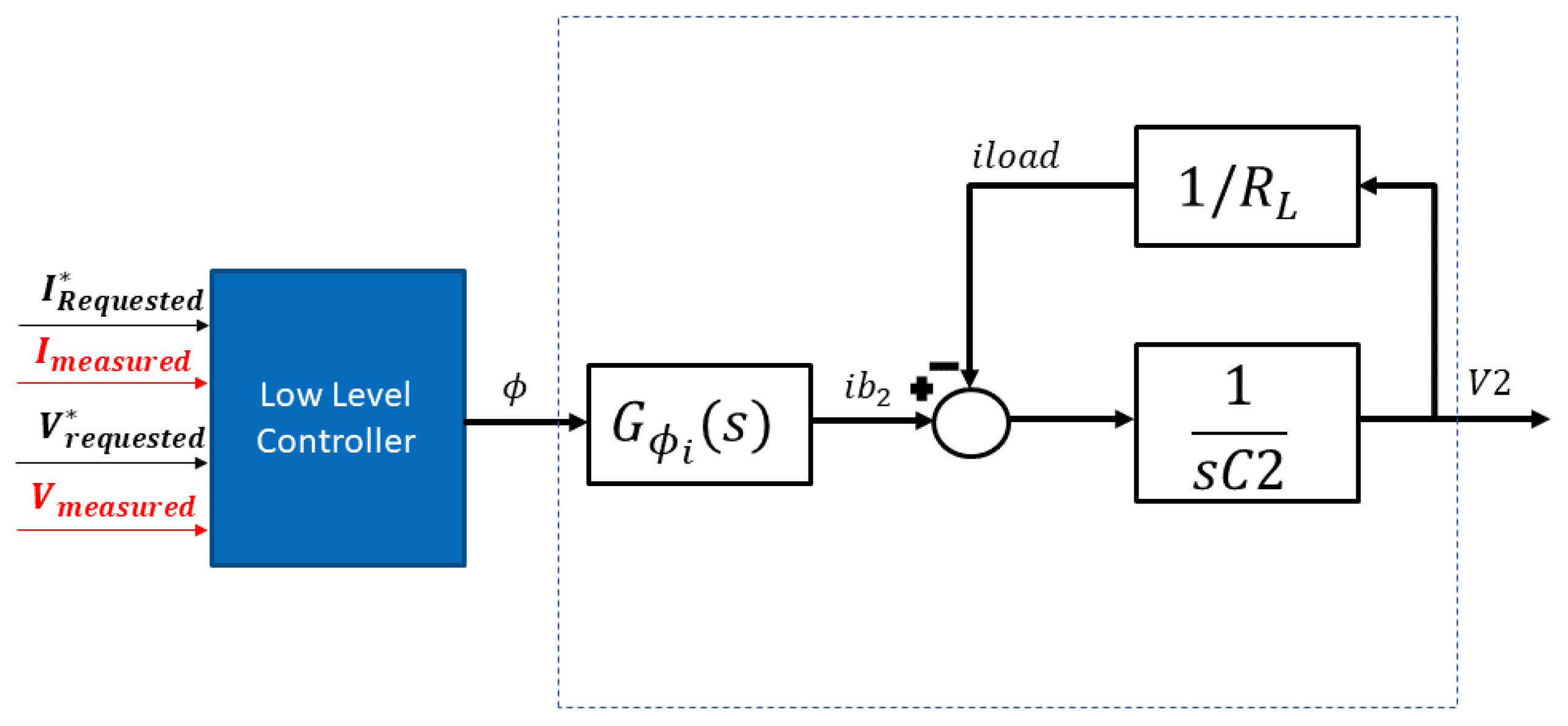
4.3.1. Feedback Control

The conventional feedback proportional-integral (PI) control algorithm is the simplest algorithm in the literature [13,92,123,126]. It could be implemented for all APM control modes (e.g., CC and CV modes). However, for each control mode, the PI controller proportional gain ( k p ) and integral gain ( k i ) have to be tuned independently [111]. In CV mode, the voltage control loop is the slower loop and is implemented as the outer control loop. The current-control loop is implemented as a faster inner loop with an updated rate of at least twice the switching frequency. This is mainly to limit the switch’s current against unrequired transients [13]. Figure 35a demonstrates the APM controller block diagram for the CV mode of operation. In addition, Figure 35b shows the implementation of the APM controller block diagram for the CC mode of operation.

4.3.2. Feedforward Plus Feedback Control

Combining feedforward plus feedback control improves the dynamic performance of the controller and reduces the effect of fast load transients or reference step voltage changes [129]. Output load current feedforward improves the dynamic performance of a DAB converter in CV control mode [116,129]. On the other hand, the average value of the DAB converter input and output voltages can be used in feedforward control for the CC control mode [124].
In the case of the output load current feedforward control technique, the DAB converter’s load current is measured, and the required phase shift angle for the corresponding load current is feedforward to the current-control loop using Equation (11) [116]. In [55], another solution was proposed for estimating the optimum phase shift angle using predefined lookup tables for different power levels. Figure 36 demonstrates the block diagram of the load current feedforward control for CV control mode. For the CC control mode, a feedforward control algorithm was proposed for the input and output voltages for the 400 V–48 V APM application, as shown in Figure 37 [124].
Φ * = { 1 4 1 16 n f s w   L I L V   V H V                           I L V 0 1 4 + 1 16 + n   f s w   L I L V   V H V                           I L V < 0                                                            

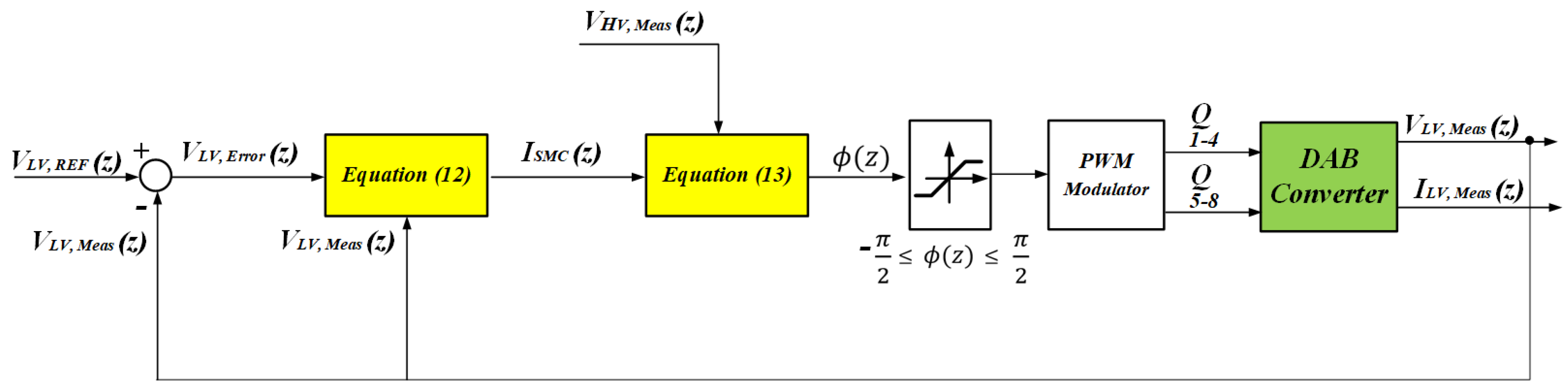
4.3.3. Sliding Mode Control

The accuracy of the tuning method of the PI controller gains, such as the Ziegler-Nicholas (ZN) method, depends on the accuracy of the small-signal model of the system. However, the small-signal analysis is done at rated operating conditions, and it could fail to predict the system’s stability in the complete operating range [116,126].
The recent literature focuses on using non-linear control techniques, such as fuzzy logic control and sliding mode control (SMC), to improve the controller’s dynamic performance and robustness against modeling uncertainties. SMC has many advantages, such as fast dynamic response, robustness against modeling uncertainty, and easy implementation [116,130].
Assuming reduced-order modeling of the DAB converter, where the main state variable is the output LV voltage. According to SMC theory, the controller target sliding surface is represented as shown in Equation (12). The control effort is then estimated according to Equation (13), where α 1 , α 2 , and α 3 are scalar variables [116]. Figure 38 demonstrates the SMC block diagram for the CV control mode. In [131], an SMC-based control algorithm was implemented for a 1.5 kW APM for a 340 V–70 V application. The author compared the controller performance to a PI linear-based controller algorithm in an experimental setup and concluded that the SMC controller offers better dynamic performance with zero steady-state error.
I S M C = V L V   M e a s R L + C 2 α 2 α 1   ( V L V   R e f V L V   M e a s ) + C 2 α 3 α 1 0 t ( V L V   R e f V L V   M e a s )   d t                                                                              
Φ   = { 1 4 1 16 n   f s w   L   I S M C   V H V                           I S M C 0 1 4 + 1 16 + n   f s w L   I S M C   V H V                           I S M C < 0                                                      

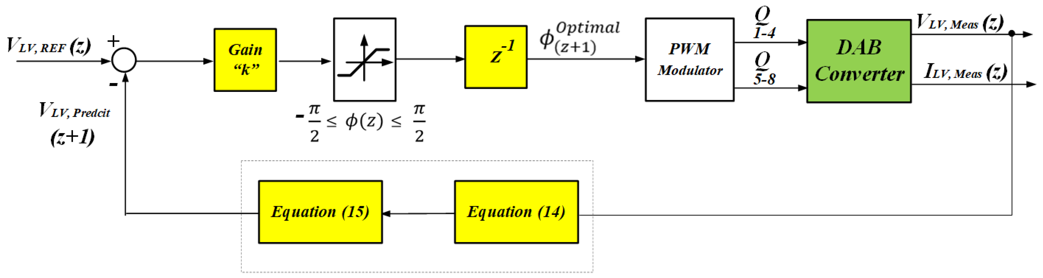
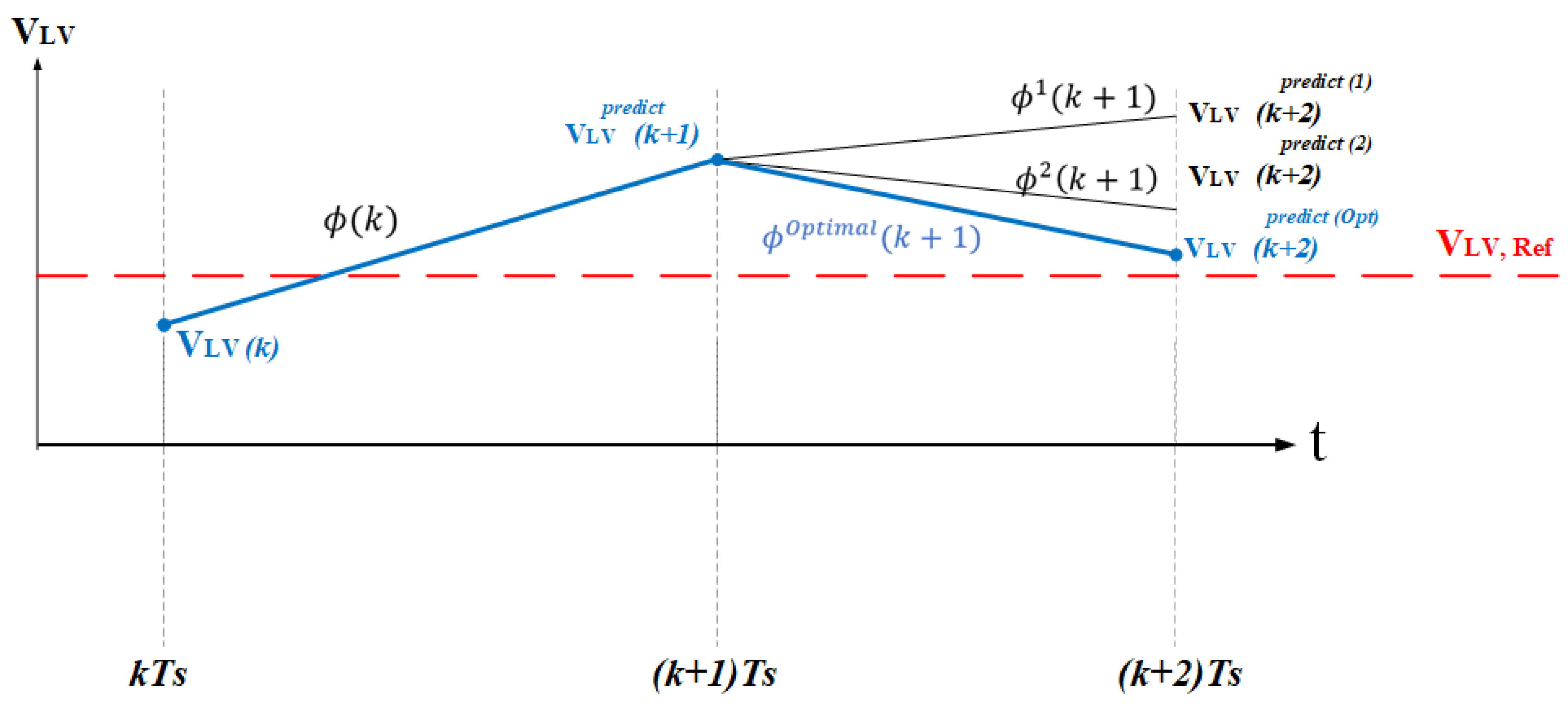
4.3.4. Model-Based Predictive Control

Model predictive control (MPC) is another non-linear control algorithm that has been intensively investigated in the last 4 years as it ensures ultimate dynamic performance [128,132,133,134]. The moving-discretized-control-set MPC algorithm (MDCS-MPC) is the most efficient algorithm for digital implementation on commercial microcontrollers [134]. The main advantage of the MDCS-MPC algorithm is that it updates the phase shift angle at each switching cycle in order to force the system to stabilize at the reference voltage in a few switching cycles.
The operation concept of the MDCS-MPC is demonstrated in Figure 39. First, at the beginning of the period [k, (k + 1)], the estimated phase shift angle ϕ ( k ) is used to predict the output LV voltage at the sampling instant (k + 1) (e.g., estimate V L V ( k + 1 ) p r e d i c t ). Then, an optimization algorithm is used to find the optimum phase shift angle that shall be applied at switching instant (k + 1), in order to bring the LV voltage as close as possible to the reference voltage at sample instant (k + 2) (e.g., estimate ϕ ( k + 1 ) O p t i m a l ). These two steps are demonstrated in Equations (14) and (15) [132]. Because of this working concept, the MDCS-MPC is known to predict the output voltage in two future sampling periods [116]. Figure 40 shows the MDCS-MPC block diagram.
V L V   ( k + 1 )   p r e d i c t = f ( ϕ ( k ) )   V L V   ( k )     p r e d i c t      
m i n   (   J   ( V L V   ( k + 1 ) p r e d i c t   ,   ϕ ( k + 1 ) )   ) = > ϕ ( k + 1 ) O p t i m a l        
In [135], the transient responses of PI feedback and MPC controllers were compared. The results showed that the MPC controller reduced the overshot response in comparison to the PI controller. However, the main drawback of the MPC controller is the computational effort.
To conclude, Table 6 shows a quantitative comparison between the different DAB converter control techniques’ response times for an overdamped DAB converter system response.

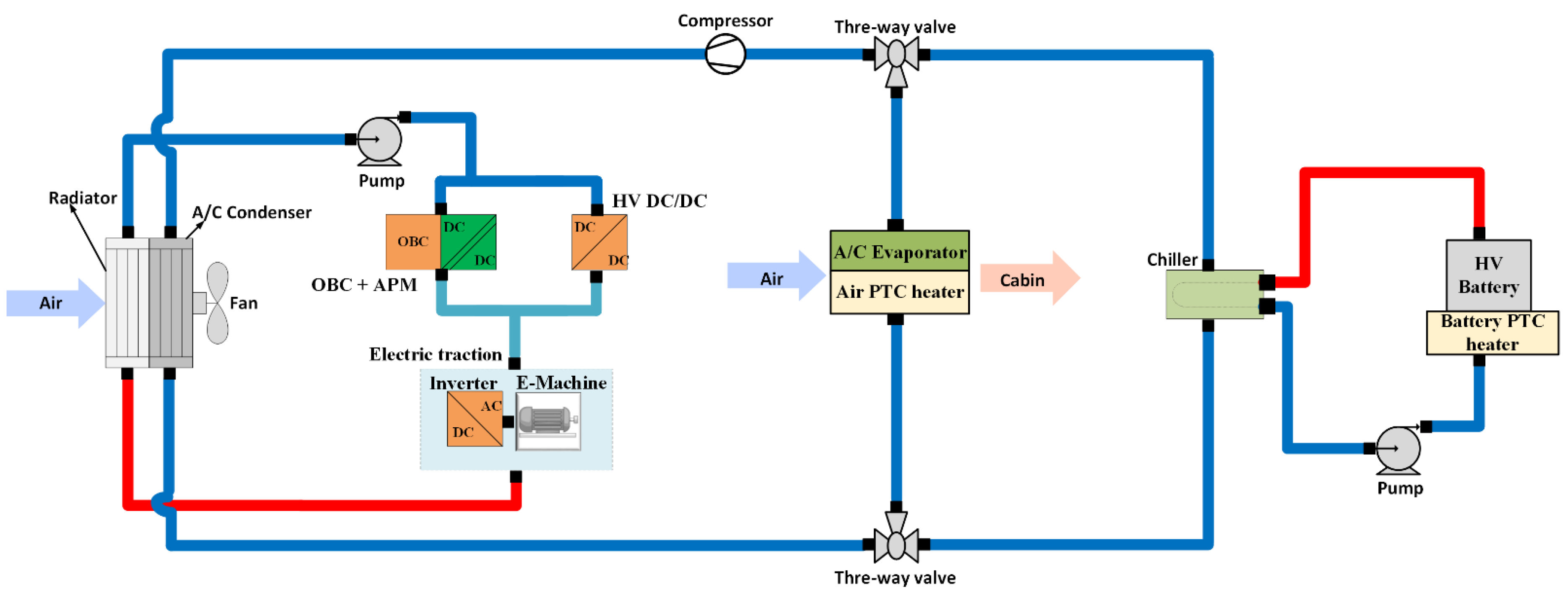
5. Cooling Circuit of Automotive DC-DC Converters

Thermal management of an EV has always been a crucial task. Firstly, in order to reach the maximum power limits of the power electronic systems (e.g., the onboard charger, inverter, and APM), a highly efficient cooling system that keeps each system’s hot spot within limits is required. Secondly, the thermal system is responsible for the lifetime of the EV components.
As shown in Figure 41, the cooling system of an EV comprises three cooling loops, e.g., a high-temperature loop for powertrain components, a low-temperature loop for battery, and a cabin loop (air conditioning AC loop). The APM and the onboard charger system have lower power ratings and lower power losses than the powertrain electric drive system (inverter + E-motor). Therefore, the APM and the onboard charger are placed before the electric drive in the cooling cycle.
The cabin loop includes an AC conditioning unit and a cabin heater to provide the required heat flows to the vehicle interior and ensure the passengers’ comfort [137]. Meanwhile, the battery thermal management loop controls the HV battery temperature range between 25 °C and 45 °C. This temperature range ensures the high efficiency and full performance requirements of the EV’s HV battery [138]. On the contrary, the temperature range of the powertrain cooling loop is comparatively high, between 30 °C and 80 °C. The cooling loop of the powertrain components consists of all power electronics devices, namely the inverter, LV DC-DC converter, onboard charger, and electric motor. Moreover, an e-radiator is used in this cooling loop to release heat to the outside air.
Previously, the APM cooling technique seemed to be a forced air-cooled-based solution. This was feasible due to the low power rating and the consequent low power dissipation requirements (~3–7% of 3.7 kW < 260 W) [13]. A total cooling area of ~0.1–0.5 m 2 was needed to dissipate these powers. The power density of the APM was 0.5 kW/L for the Nissan Leaf in the year 2015. In current EV applications, WBG semiconductors and liquid cooling systems enable higher efficiency and power density. For instance, Vitesco Technology reported up to 95.4% efficiency and a power density of 1.5 kW/L. To illustrate, the 3.5 kW system from Vitesco Technology [139], and the 3.6 kW DC-DC converter from Bosh [140]. In current solutions, liquid cooling is utilized to accommodate the overall size reduction, since air cooling demands a relatively large contact area, prohibiting the scale-down of the cooling volume.
In the future, the automotive sector is projected to further increase the power density of the APM up to 2.5 kW/L. Therefore, more compact and efficient cooling solutions are required to achieve the ambitious projected power density. New cooling concepts will be developed to carry away more heat from a smaller area or volume. Where possible, the components will be made into a sandwich (cooling, PCB layer, capacitor). Besides, more innovative cooling strategies will be considered for cooling automotive APMs, such as two-phase evaporative cooling, as it allows less cold plate volume and weight, to provide a more compact and more energy-intensive solution.

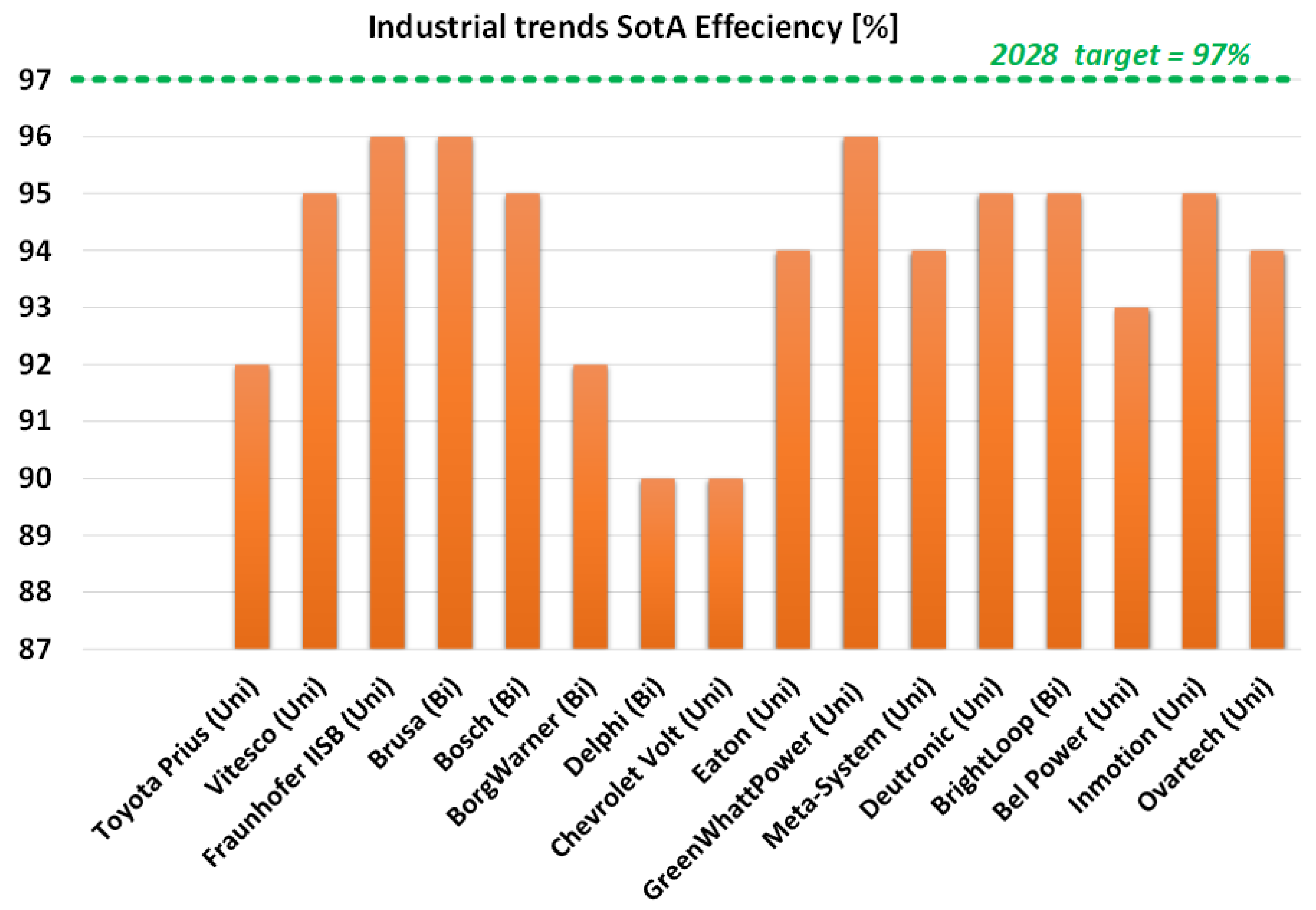
6. APM Industrial Trends

According to the author’s best knowledge, no literature has been explicitly found where any vehicle OEMs and/or tier-1/2 suppliers claimed to use modular multiport DC-DC converters for the APM application. Moreover, only a few solutions are enlisted for the 800 V–12 V voltage step-down application.
Currently, automotive OEMs are investing in R&D to achieve greater freedom to adapt to manufacturers’ different electrical system configurations using one box solution. Therefore, there is a growing demand from OEMs for multiple output voltage options on the low-voltage side using a modular multiport converter for a high-voltage battery pack; hence, all units could be controlled by intelligent software and with facilities for data recording for predictive health maintenance to ensure fail-safe operation.
To summarize the current industrial SotA, Figure 42 demonstrates the trend in the APM efficiencies from 16 different companies. Furthermore, Figure 43 and Figure 44 show the industrial trend of the power density (kW/L) and the specific power density (kW/kg).
Table 7 summarizes the results of the industrial research analysis. As can be understood from Table 7, the cooling technique has a big influence on increasing the power density of the system.
To sum up, the minimum efficiency for a multiport APM must be higher than 97%. Fraunhofer research center succeeded in developing a 5 kW/L multiport APM system. However, the design could only support a unidirectional power supply. In addition, Brightloop company’s GaN-based APM system showed a high specific power density of 2 kW/kg. Therefore, the target design should be at least 2.5 kW/kg.

7. Conclusions

This paper comprehensively reviews the auxiliary APM system for automotive applications. The consistent development in the EV industry and the future trend of an increasing number of autonomous vehicles on the roads will inevitably result in more requirements for the APM system. The HV-LV isolated DC-DC converter must supply several LV networks (e.g., 12 V, 24 V, and 48 V) from the HV traction battery (e.g., 320–800 V). Since the automotive OEMs started to shift from the traditional 12 V LV system to 24 V and 48 V systems, new design requirements and safety recommendations must have been imposed to achieve higher efficiency, power density, and reliability.
Firstly, the APM current SotA system requirements, standards, and main design challenges have been discussed. The main HW design constraint is to include galvanic isolation using a high-frequency solid-state transformer. This is mainly to prevent the triggering of ground loops between the HV network and the LV network in the EV. In addition, the design shall approve electrical safety standards, such as ISO 6469-3 and ISO 26,262. Furthermore, the design must comply with LV 123/124 standards, which define the LV network voltage requirements and battery charging/discharging requirements. In addition, the design of the input/output filters must ensure EMC compatibility. Finally, the design must achieve a minimum efficiency of 97%, and a power density of at least 2 kW/L, as compared to current industry trends. Implementing WBG semiconductor technology, such as SiC and GaN, can help achieve these targets. In addition, a highly efficient liquid cooling system is essential to increase the power density beyond the SotA.
Secondly, various isolated DC-DC converter topologies have been reviewed and categorized. According to the current SotA, the APM topologies must allow bidirectional power flow. This increases the reliability of the EV when the HV traction battery fails. After a comprehensive analysis, it was found that the dual active bridge (DAB) topology has several advantages, such as galvanic isolation, simple bidirectional power flow control, and extending the topology for higher power ratings. The authors in this paper proposed a topology for a modular SIMO APM system based on comparative analysis. The topology consists of a DAB converter stage, and an interleaved non-isolated buck-boost stage. The DAB stage is used for the HV<-> 48 V stepping-up/down, and for the bidirectional power flow control. On the other hand, the buck-boost stage can be used for the 48 <->12/24 voltage conversion. The 12/24 V ports can be regulated by controlling the buck-boost duty ratio.
Thirdly, the modeling methods of a DAB converter have been reviewed. A qualitative comparison has been made between the three modeling methods of the DAB converter. The simplest modeling method is the reduced-order modeling method, in which the transformer currents’ transients are neglected. However, this method lacks the ability to accurately realize the system losses and the high-frequency components in the currents and voltages. On the other hand, the discrete-time state-space full-order model can accurately predict system losses and shows high small-signal modeling accuracy. Despite that, full-order modeling suffers from complexity in building state-space matrices.
After that, the most common linear and non-linear control techniques of the DAB converter were analyzed and compared in terms of response time, dynamic behavior, and the complexity of implementing the control algorithm. Linear feedforward plus feedback control is the simplest technique with a moderate response time. It can be used for both the CC and CV control modes of the APM. On the other hand, the model predictive control inherits excellent dynamic behavior for the controlled signals. However, it suffers from implementation complexity.
Next, the thermal management system of an EV has been demonstrated because it is an essential factor in optimizing THE power density of the APM. To sum up, the EV includes three main cooling circuits. The first cooling circuit is the interior cabin cooling circuit. Secondly, the HV traction battery cooling circuit controls the HV traction battery’s temperature between 25 °C and 45 °C. This range ensures optimum performance for the HV battery. Thirdly, the EV’s electric powertrain cooling circuit. The APM is placed in a series of powertrain components (e.g., the inverter and e-motor). However, it must be placed before the traction system because the dissipated heat losses of the APM are much less than those of the electric traction system.
Lastly, the current SotA industrial trends of the APM systems from 16 different companies were compared and analyzed. The next generation of a multiport APM must achieve a minimum efficiency of 97%. Furthermore, with respect to power density, the Fraunhofer Research Center succeeded in developing a 5 kW/L multiport APM system. However, the design could only support a unidirectional power supply. Furthermore, with respect to specific power density, the GaN-based APM system of the Brightloop company showed a high specific power density of 2 kW/kg. Therefore, the future design’s target will be at least 2.5 kW/kg.
Overall, this comprehensive survey and comparative study are expected to be a reference guide for academic researchers and automotive OEMs in further research and improving the performance metrics of the APM system.

Author Contributions

Conceptualization, R.K.; methodology, R.K. and S.C.; illustration, R.K.; formal analysis, R.K., S.C. and D.-D.T.; investigation, R.K. and S.C.; resources, R.K., S.C., D.-D.T. and E.A.; data curation, R.K., S.C. and E.A.; writing—original draft preparation, R.K.; writing—review and editing, S.C., D.-D.T., E.A., M.E.B. and O.H.; supervision, O.H.; project administration, S.C.; funding acquisition, O.H. All authors have read and agreed to the published version of the manuscript.

Funding

This research was funded by VUB PhD scholarship.

Data Availability Statement

Not applicable.

Acknowledgments

We, as authors, acknowledge Flanders Make for the support to our research group.

Conflicts of Interest

The authors declare no conflict of interest.

References

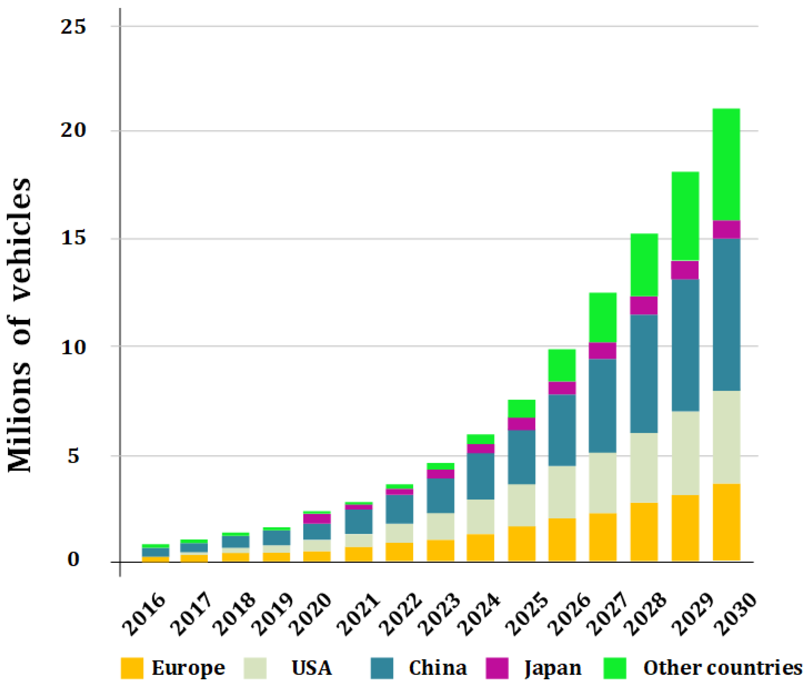
  1. Global growth of the electric vehicle market. Bloomberg New Energy Finance, 9 August 2021.
  2. Ghosh, A. Possibilities and challenges for the inclusion of the electric vehicle (EV) to reduce the carbon footprint in the transport sector: A review. Energies 2020, 13, 2602. [Google Scholar] [CrossRef]
  3. López, I.; Ibarra, E.; Matallana, A.; Andreu, J.; Kortabarria, I. Next generation electric drives for HEV/EV propulsion systems: Technology, trends and challenges. Renew. Sustain. Energy Rev. 2019, 114, 109336. [Google Scholar] [CrossRef]
  4. Monteiro, V.; Afonso, J.A.; Ferreira, J.C.; Afonso, J.L. Vehicle electrification: New challenges and opportunities for smart grids. Energies 2019, 12, 118. [Google Scholar] [CrossRef]
  5. Patel, N.; Kumar Bhoi, A.; Padmanaban, S.; Holm-Nielsen, J.-B. Green Energy and Technology Electric Vehicles Modern Technologies and Trends. Available online: http://www.springer.com/series/8059 (accessed on 1 July 2022).
  6. Byrne, D. An engineer’s guide to the DC power train architecture of an electric vehicle. In The Specialist in Electronic Component Distribution; TTI, Inc.: Maisach-Gernlinden, Germany, 2017. [Google Scholar]
  7. VARTA. The Role of 12 Volt Batteries in Electric Vehicles. 22 January 2021. Available online: https://batteryworld.varta-automotive.com/en-be/12-volt-batteries-in-electric-vehicles (accessed on 31 October 2022).
  8. Chen, Y.; Liu, W.; Yurek, A.; Zhou, X.; Sheng, B.; Liu, Y.F. Design and Optimization of a High Power Density Low Voltage DC-DC Converter for Electric Vehicles. In Proceedings of the ECCE 2020—IEEE Energy Conversion Congress and Exposition, Detroit, MI, USA, 11–15 October 2020; pp. 1244–1251. [Google Scholar] [CrossRef]
  9. Repecho, V.; Olm, J.M.; Grino, R.; Doria-Cerezo, A.; Fossas, E. Modelling and Nonlinear Control of a Magnetically Coupled Multiport DC-DC Converter for Automotive Applications. IEEE Access 2021, 9, 63345–63355. [Google Scholar] [CrossRef]
  10. Institute of Electrical and Electronics Engineers. Towards a Viable Autonomous Driving Research Platform. In Proceedings of the 2013 IEEE Intelligent Vehicles Symposium, IV 2013, Gold Coast City, Australia, 23–26 June 2013. [Google Scholar]
  11. Elprocus. Power Electronics Application in Automotive Electronics. 2013. Available online: https://www.elprocus.com/power-electronics-in-automotive-applications/ (accessed on 3 January 2023).
  12. Buechel, M.; Frtunikj, J.; Becker, K.; Sommer, S.; Buckl, C.; Armbruster, M.; Marek, A.; Zirkler, A.; Klein, C.; Knoll, A. An Automated Electric Vehicle Prototype Showing New Trends in Automotive Architectures. In Proceedings of the IEEE Conference on Intelligent Transportation Systems, ITSC, Gran Canaria, Spain, 15–18 October 2015; pp. 1274–1279. [Google Scholar] [CrossRef]
  13. Hasan, S.N.; Anwar, M.N.; Teimorzadeh, M.; Tasky, D.P. Features and challenges for Auxiliary Power Module (APM) design for hybrid/electric vehicle applications. In Proceedings of the 2011 IEEE Vehicle Power and Propulsion Conference, Chicago, IL, USA, 6–9 September 2011; pp. 1–6. [Google Scholar]
  14. Yu, G.; Choi, S. Auxiliary Power Module—Integrated EV Charger with Extended ZVS range. In Proceedings of the ECCE 2020—IEEE Energy Conversion Congress and Exposition, Detroit, MI, USA, 11–15 October 2020; pp. 628–632. [Google Scholar] [CrossRef]
  15. Millan, J.; Godignon, P.; Perpina, X.; Perez-Tomas, A.; Rebollo, J. A survey of wide bandgap power semiconductor devices. IEEE Trans. Power Electron. 2014, 29, 2155–2163. [Google Scholar] [CrossRef]
  16. Ye, M.; Xu, P.; Yang, B.; Lee, F. Investigation of topology candidates for 48V VRM. In Proceedings of the Conference Proceedings—IEEE Applied Power Electronics Conference and Exposition—APEC, Dallas, TX, USA, 10–14 March 2002; Volume 2, pp. 699–705. [Google Scholar] [CrossRef]
  17. Faunhofer. Isolated High Voltage DC-DC Converters for Auxiliary Power Supply in Electric Vehicles. Erlangen. Available online: www.iisb.fraunhofer.de (accessed on 3 June 2022).
  18. Zhu, L.; Bai, H.; Brown, A.; McAmmond, M. Design a 400 V-12 v 6 kW Bidirectional Auxiliary Power Module for Electric or Autonomous Vehicles with Fast Precharge Dynamics and Zero DC-Bias Current. IEEE Trans Power Electron. 2021, 36, 5323–5335. [Google Scholar] [CrossRef]
  19. Brusa Company. BSC66-Bidirectional Auxiliary Supply Converter. Available online: www.brusa.biz (accessed on 5 June 2022).
  20. Kieu, H.P.; Lee, D.; Choi, S.; Kim, S. A 700 kHz 800V/14V GaN-based DC-DC Converter with Optimized Integrated Transformer for Electrical Vehicles. In Proceedings of the 2021 IEEE Energy Conversion Congress and Exposition, ECCE, Vancouver, BC, Canada, 10–14 October 2021; pp. 5549–5553. [Google Scholar] [CrossRef]
  21. Institute of Electrical and Electronics Engineers. In Proceedings of the 21st European Conference on Power Electronics and Applications (EPE ’19 ECCE Europe), Genova, Italy, 6–10 September 2021.
  22. Foray, E. Design of an Integrated High-Voltage Low-Power Isolated DC/DC Converter for Automotive Applications—Conception d’un Convertisseur DC/DC Isolé, Intégré, Haute-Tension et Basse-Puissance Pour Applications Automobiles. Available online: http://theses.insa-lyon.fr/publication/2021LYSEI043/these.pdf (accessed on 8 July 2022).
  23. ISO 6469-3:2018; Electrically Propelled Road Vehicles—Safety Specifications—Part 3: Electrical Safety. ISO: Geneva, Switzerland, 2018.
  24. Silicon Labs. Quick Reference Guide Isolation in Electric Vehicle Systems. 2021. Available online: https://www.silabs.com/products/isolation/automotive-isolation (accessed on 10 December 2022).
  25. Institute of Electrical and Electronics Engineers. Tenn. Electrical Manufacturing Expo. In Proceedings of the Electrical Insulation Conference and Electrical Manufacturing & Coil Winding Conference, Nashville, TN, USA, 22–24 October 2007. [Google Scholar]
  26. Geramirad, H.; Morel, F.; Dworakowski, P.; Lefebvre, B.; Lagier, T.; Camail, P.; Vollaire, C.; Bréard, A. Conducted EMI Reduction in a 100kW 1.2kV Dual Active Bridge Converter. 2020. Available online: https://hal.archives-ouvertes.fr/hal-02942284v2 (accessed on 14 November 2022).
  27. Deutronic Company. DC-DC Converter. Available online: https://www.deutronic.com/wp-content/uploads/2021/01/DVCH3000_ds.pdf (accessed on 23 August 2022).
  28. WKS Informatik Solutions. LV 124/LV 148 Standard Tests. Available online: https://www.wks-informatik.de/wp-content/uploads/DocumentDownloads/June2017/LV124_LV148_WKSInformatikSolutions.pdf (accessed on 18 August 2022).
  29. A. N. Introduction. EMC Testing on Electric Vehicles. 2020. Available online: https://www.ametek-cts.com/know-how/electric-vehicles-emc-testing (accessed on 4 October 2022).
  30. Everts, J. Design and optimization of an efficient (96.1%) and compact (2 kW/dm3) bidirectional isolated single-phase dual active bridge AC-DC converter. Energies 2016, 9, 799. [Google Scholar] [CrossRef]
  31. Solomon, A. How to Implement Automated Tests for the Electrical Tests of the LV 124 and LV 148 Automotive Standards. WKS Informatik GmbH. Available online: www.wks-informatik.de (accessed on 10 December 2018).
  32. Veeramanikandan, M.; Vavilapalli, K.R.; Jeevan, N.K. HiL Testing of Automotive Transients in Electric Vehicle; SAE Technical Paper; SAE International: Warrendale, PA, USA, 2022. [Google Scholar]
  33. Haspl, A.; Leighton, M. Winkler. Reduction of Testing Time of PTCE/HTOE Tests Based on Real Road Load Profiles; 2022-01-0176; SAE International: Warrendale, PN, USA, 2022. [Google Scholar]
  34. Jain, A.G.D. Power Analog Design Journal Automotive EMC-Compliant Reverse-Battery Protection with Ideal-Diode Controllers. 2020. Available online: https://www.ti.com/lit/an/slyt802/slyt802.pdf?ts=1675712117315&ref_url=https%253A%252F%252Fwww.google.com%252F (accessed on 3 December 2022).
  35. ZVEI-Task Force Voltage Classes. Voltage Classes for Electric Mobility. Frankfurt, Decembar 2013. Available online: https://www.zvei.org/fileadmin/user_upload/Presse_und_Medien/Publikationen/2014/april/Voltage_Classes_for_Electric_Mobility/Voltage_Classes_for_Electric_Mobility.pdf (accessed on 29 May 2022).
  36. Parikh, P.; Smith, K.; Barr, R.; Shono, K.; McKay, J.; Shen, L.; Lal, R.; Chowdhury, S.; Yea, S.; Smith, R.P.; et al. 650 volt GaN commercialization reaches automotive standards. ECS Trans. 2017, 80, 17. [Google Scholar] [CrossRef]
  37. Green, R.; Lelis, A.; Habersat, D. Application of reliability test standards to SiC Power MOSFETs. In Proceedings of the 2011 International Reliability Physics Symposium, Monterey, CA, USA, 10–14 April 2011; p. EX-2. [Google Scholar]
  38. Lee, S. Test Standard for Reliability of Automotive Semiconductors: AEC-Q100. J. IKEEE 2021, 25, 578–583. [Google Scholar]
  39. Jain, H.; Rajawat, S.; Agrawal, P. Comparision of wide band gap semiconductors for power electronics applications. In Proceedings of the 2008 International Conference on Recent Advances in Microwave Theory and Applications, Jaipur, India, 21–24 November 2008; pp. 878–881. [Google Scholar]
  40. Morya, A.; Moosavi, M.; Gardner, M.; Toliyat, H. Applications of Wide Bandgap (WBG) devices in AC electric drives: A technology status review. In Proceedings of the 2017 IEEE International Electric Machines and Drives Conference (IEMDC), Miami, FL, USA, 21–24 May 2017; pp. 1–8. [Google Scholar]
  41. Chen, R.; Wang, F.F. SiC and GaN devices with cryogenic cooling. IEEE Open J. Power Electron. 2021, 2, 315–326. [Google Scholar] [CrossRef]
  42. Zhang, Y.; Singh, J. Charge control and mobility studies for an AlGaN/GaN high electron mobility transistor. J. Appl. Phys. 1999, 85, 587–594. [Google Scholar] [CrossRef]
  43. Meneghesso, G.; Verzellesi, G.; Danesin, F.; Rampazzo, F.; Zanon, F.; Tazzoli, A.; Meneghini, M.; Zanoni, E. Reliability of GaN high-electron-mobility transistors: State of the art and perspectives. IEEE Trans. Device Mater. Reliab. 2008, 8, 332–343. [Google Scholar] [CrossRef]
  44. Boteler, L.; Lelis, A.; Berman, M.; Fish, M. Thermal conductivity of power semiconductors—When does it matter? In Proceedings of the 2019 IEEE 7th Workshop on Wide Bandgap Power Devices and Applications (WiPDA), Raleigh, NC, USA, 29–31 October 2019; pp. 265–271. [Google Scholar]
  45. Liu, G.; Bai, K.H.; McAmmond, M.; Brown, A.; Johnson, P.M.; Taylor, A.; Lu, J. Comparison of SiC MOSFET-based and GaN HEMT-based high-efficiency high-power-density 7.2 kW EV battery chargers. IET Power Electron. 2018, 11, 1849–1857. [Google Scholar]
  46. Zhaksylyk, A. Implementation of a Phase Shifted Full bridge DC-DC ZVS Converter with Peak Current Mode Control. Ph.D. Thesis, Vrije Universiteit Brussel, Brussels, Belgium, 2019. [Google Scholar]
  47. Rashid, M.H.; Hui, S.Y.; Shu-Hung Chung, H. Resonant and soft-switching converters. In Power Electronics Handbook; Elsevier: Amsterdam, The Netherlands, 2018; pp. 339–383. [Google Scholar] [CrossRef]
  48. Texas Instruments. Phase Shifted Full Bridge, Zero Voltage Transition Design Considerations; Texas Instruments: Dallas, TX, USA, 2011. [Google Scholar]
  49. Ashique, R.H.; Salam, Z.; Maruf, M.H.; Shihavuddin, A.; Islam, M.T.; Rahman, M.F.; Kotsampopoulos, P.; Fayek, H.H. A Comparative Analysis of Soft Switching Techniques in Reducing the Energy Loss and Improving the Soft Switching Range in Power Converters. Electronics 2022, 11, 1062. [Google Scholar] [CrossRef]
  50. Kolar, J.W.; Drofenik, U.; Biela, J.; Heldwein, M.L.; Ertl, H.; Friedli, T.; Round, S.D. PWM Converter Power Density Barriers. In Proceedings of the 2007 Power Conversion Conference—Nagoya, Nagoya, Japan, 2–5 April 2007. [Google Scholar]
  51. Kirlin, R.; Bech, M.; Trzynadlowski, A. Analysis of power and power spectral density in PWM inverters with randomized switching frequency. IEEE Trans. Ind. Electron. 2002, 49, 486–499. [Google Scholar] [CrossRef]
  52. Glaser, J.S.; Nasadoski, J.; Heinrich, R. A 900W, 300V to 50V Dc-dc power converter with a 30MHz switching frequency. In Proceedings of the IEEE Applied Power Electronics Conference and Exposition—APEC, Washington, DC, USA, 15–19 February 2009; pp. 1121–1128. [Google Scholar] [CrossRef]
  53. Meta System. High Voltage DC-DC Converter. Available online: https://www.metasystem.it/en/e-mobility (accessed on 23 August 2022).
  54. Elton Company. High-Voltage DC/DC Converters for Electric Vehicles. Available online: https://www.eaton.com/content/dam/eaton/products/emobility/power-electronics/dc-dc-converters/eaton-dcdc-converter-data-sheet-brochure-emob0008-en-us.pdf (accessed on 23 August 2022).
  55. Daneshpajooh, H.; Bakhshai, A.; Jain, P. Optimizing Dual Half Bridge Converter for Full Range Soft Switching and High Efficiency. In Proceedings of the IEEE Energy Conversion Congress and Exposition: Energy Conversion Innovation for a Clean Energy Future, ECCE 2011, Phoenix, AZ, USA, 17–22 September 2011; pp. 1296–1301. [Google Scholar] [CrossRef]
  56. Texas Insturments. BI-Directional, Dual Active Bridge Reference Design for Level 3 Electric Vehicle Charging Station; Texas Instruments: Dallas, TX, USA, 2019. [Google Scholar]
  57. Mukherjee, S.; Kumar, A.; Chakraborty, S. Comparison of DAB and LLC DC-DC Converters in High-Step-Down Fixed-Conversion-Ratio (DCX) Applications. IEEE Trans. Power Electron. 2021, 36, 4383–4398. [Google Scholar] [CrossRef]
  58. Schäfer, J.; Bortis, D.; Kolar, J.; Schäfer, J.; Bortis, D. Multi-Port Multi-Cell DC/DC Converter Topology for Electric Vehicle’s Power Distribution Networks. In Proceedings of the 2017 IEEE 18th Workshop on Control and Modeling for Power Electronics (COMPEL), Stanford, CA, USA, 9–12 July 2017. [Google Scholar] [CrossRef]
  59. Delphi Company. Delphi Universal 2.2kW DC-DC Converter. Available online: https://www.elmofo.com.au/delphi-universal-2-2kw-dc-dc-converter.html?__cf_chl_jschl_tk__=129263ca3944ae17550d92ae839add7065273ac1-1624956228-0-AYUeKuScL0CvAOGtNx3yc7_Y_OuTfQNOP69Rf2ixt_jJmjbL0iZkCYBGBZOPXsoN-4MXRCyOZ92oifIX0C5Bwf3lpnWDIX0xrYesriwpVC48gctzzfQF-Rv_66xaAoSAnodd99SNxdzBeGzODzmVult6EEJZYbRPWOhR_v4zRc_TsErfGDQUGN_WeWSliE1LWAOF5KCYE1ybyN1hLu7bd69PLFrFVWTBKjvsv9w0krKsbbuqmpGfgb4qOoaotIwNyG3r-kfEnz_AMgu_eHsQ8eTW8YlKcoTsdckku_SlNCQnxfFkD6YBzQ2We5IWuU4GBLSX3I5Wvl4f6aYNt40Qcd0L_cSkCnsmfR0NJOWg4NYrbNsANbBX4yYDKswG11IQBzc_oZbRuaKyQfF3LMRsjTpQnf0VcnhmozSFRFayM-x0ox3GAsehlQvcNpy__QD-g1MgizVpBYiP9GfX1_23DutxJ0b7gFGRk1vDkhYENEVDKp-H5iCZkUofEQLX1jSCGmd4ijWAJSbm1OgZsgGxp10 (accessed on 23 August 2022).
  60. GaN Systems. Application Success with GaN Systems 9.6 kW EV DCDC Converter. 2022. Available online: https://gansystems.com/gan-applications/brightloop/ (accessed on 29 November 2022).
  61. VDD102S360-14 SPECIFICATIONS Item Specifications. Available online: www.ovartech.com (accessed on 3 October 2022).
  62. Tang, Y.; Lu, J.; Wu, B.; Zou, S.; Ding, W.; Khaligh, A. An Integrated Dual-Output Isolated Converter for Plug-in Electric Vehicles. IEEE Trans. Veh. Technol. 2018, 67, 966–976. [Google Scholar] [CrossRef]
  63. Avila, A.; Garcia-Bediaga, A.; Alzuguren, I.; Vasic, M.; Rujas, A. A Modular Multifunction Power Converter Based on a Multiwinding Flyback Transformer for EV Application. IEEE Trans. Transp. Electrif. 2022, 8, 168–179. [Google Scholar] [CrossRef]
  64. Ling, Z.; Liang, T.; Yang, L.; Li, T. Design and implementation of interleaved quasi-resonant DC-DC flyback converter. In Proceedings of the International Conference on Power Electronics and Drive Systems, Taipei, Taiwan, 2–5 November 2009; pp. 429–433. [Google Scholar] [CrossRef]
  65. Zhang, F.; Yan, Y. Novel forward-flyback hybrid bidirectional DC-DC converter. IEEE Trans. Ind. Electron. 2009, 56, 1578–1584. [Google Scholar] [CrossRef]
  66. Hendra, A.; Hamada, F.; Yusivar, F.; Institute of Electrical and Electronics Engineers. Voltage control in push-pull DC-DC converter using state space averaging PID with soft-start for electric vehicle auxiliary system. In Proceedings of the International Conference on Instrumentation Control and Automation (ICA), Bandung, Indonesia, 31 July–2 August 2019. [Google Scholar]
  67. Sayed, K. Zero-voltage soft-switching DC-DC converterbased charger for LV battery in hybrid electric vehicles. IET Power Electron. 2019, 12, 3389–3396. [Google Scholar] [CrossRef]
  68. Duan, C.; Bai, H.; Guo, W.; Nie, Z. Design of a 2.5-kW 400/12-V High-Efficiency DC/DC Converter Using a Novel Synchronous Rectification Control for Electric Vehicles. IEEE Trans. Transp. Electrif. 2015, 1, 106–114. [Google Scholar] [CrossRef]
  69. Hou, R.; Emadi, A. Applied Integrated Active Filter Auxiliary Power Module for Electrified Vehicles with Single-Phase Onboard Chargers. IEEE Trans. Power Electron. 2017, 32, 1860–1871. [Google Scholar] [CrossRef]
  70. EPC Company. Boosting Power Density in 48 V to 5-12 V DC to DC Converter Using EPC2053, with up to 25 a Output; EPC Company: Sandpoint, ID, USA, 2018. [Google Scholar]
  71. EPC Company. APPLICATION BRIEF: AB016 eGaN® FETs and and ICs for Automotive DC-DC Applications eGaN® FETs and ICs for Automotive DC-DC Applications EFFICIENT POWER CONVERSION 48 V IN to 12 V OUT for Mild Hybrid Power; EPC Company: Sandpoint, ID, USA, 2022. [Google Scholar]
  72. Chakraborty, S.; Vu, H.; Hasan, M.; Tran, D.; el Baghdadi, M.; Hegazy, O. DC-DC converter topologies for electric vehicles, plug-in hybrid electric vehicles and fast charging stations: State of the art and future trends. Energies 2019, 12, 569. [Google Scholar] [CrossRef]
  73. Lipu, M.S.H.; Faisal, M.; Ansari, S.; Hannan, M.A.; Karim, T.F.; Ayob, A.; Hussain, A.; Miah, M.S.; Saad, M.H.M. Review of Electric Vehicle Converter Configurations, Control Schemes and Optimizations: Challenges and Suggestions. Electronics 2021, 10, 477. [Google Scholar] [CrossRef]
  74. Emrani, A.; Adib, E.; Farzanehfard, H. Single-switch soft-switched isolated DC-DC converter. IEEE Trans. Power Electron. 2012, 27, 1952–1957. [Google Scholar] [CrossRef]
  75. Rashid, M.H. Power Electronics Circuits, Devices, and Applications, 3rd ed.; Pearson Education, Inc.: Delhi, India, 2004. [Google Scholar]
  76. Batarseh, I.; Wei, H. Power factor correction circuits. In Power Electronics Handbook; Butterworth-Heinemann: Oxfrodm, UK, 2011; pp. 523–547. [Google Scholar]
  77. Siwakoti, Y.P.; Forouzesh, M.; Pham, N.H. Power electronics converters-an overview. In Control of Power Electronic Converters and Systems; Elsevier: Amsterdam, The Netherlands, 2018; pp. 3–29. [Google Scholar] [CrossRef]
  78. Hack, T. Flyback controller improves cross regulation for multiple output applications. In Analog Circuit Design; Elsevier: Amsterdam, The Netherlands, 2015; pp. 497–498. [Google Scholar] [CrossRef]
  79. Baba, D. Isolated Supply Overview and Design Trade-Offs Literature Number: SNVA603 POWER Designer Expert tips, Tricks, and Techniques for Powerful Designs Isolated Supply Overview and Design Trade-Offs; Texas Instruments: Dallas, TX, USA, 2009. [Google Scholar]
  80. Severns, R. The history of the forward converters. Switch. Power Mag. 2000, 1, 20–22. [Google Scholar]
  81. Habumugisha, D.; Chowdhury, S.; Chowdhury, S.P. A DC-DC interleaved forward converter to step—Up DC voltage for DC Microgrid applications. In Proceedings of the IEEE Power and Energy Society General Meeting, Vancouver, BC, Canada, 21–25 July 2013. [Google Scholar] [CrossRef]
  82. Roasto, I.; Vinnikov, D.; Lehtla, T. Analysis of capacitor-related mid-voltage point shift problems in high-voltage half-bridge DC/DC converters. In Proceedings of the 2008 IEEE Power Electronics Specialists Conference, Rhodes, Greece, 15–19 June 2008; pp. 3619–3622. [Google Scholar]
  83. Hou, R.; Magne, P.; Bilgin, B.; Emadi, A. A topological evaluation of isolated DC/DC converters for Auxiliary Power Modules in Electrified Vehicle applications. In Proceedings of the Conference Proceedings—IEEE Applied Power Electronics Conference and Exposition—APEC, Charlotte, NC, USA, 15–19 May 2015; Volume 2015, pp. 1360–1366. [Google Scholar] [CrossRef]
  84. Baggio, J.E.; Hey, H.; Gründling, H.; Pinheiro, H.; Pinheiro, J.R. Isolated interleaved-phase-shift-PWM DC-DC ZVS converter. IEEE Trans. Ind. Appl. 2003, 39, 1795–1802. [Google Scholar] [CrossRef]
  85. Zhang, J.; Xie, X.; Wu, X.; Qian, Z. Comparison study of phase-shifted full bridge ZVS converters. In Proceedings of the PESC Record—IEEE Annual Power Electronics Specialists Conference, Aachen, Germany, 20–25 June 2004; Volume 1, pp. 533–539. [Google Scholar] [CrossRef]
  86. Badstuebner, U.; Biela, J.; Christen, D.; Kolar, J. Optimization of a 5-kW telecom phase-shift dc-dc converter with magnetically integrated current doubler. IEEE Trans. Ind. Electron. 2011, 58, 4736–4745. [Google Scholar] [CrossRef]
  87. Deshmukh, S.; Iqbal, A.; Islam, S.; Khan, I.; Marzband, M.; Rahman, S.; Al-Wahedi, A.M. Review on classification of resonant converters for electric vehicle application. Energy Rep. 2022, 8, 1091–1113. [Google Scholar] [CrossRef]
  88. Koscelnik, J.; Frivaldsky, M.; Prazenica, M.; Mazgut, R. A Review of Multi-Elements Resonant Converters Topologies. In Proceedings of the 10th International Conference, Rajecke Teplice, Slovakia, 19–20 May 2014; pp. 312–317. [Google Scholar] [CrossRef]
  89. Salem, M.; Yahya, K. Resonant Power Converters. Available online: www.intechopen.com (accessed on 15 September 2022).
  90. Yu, S.-Y.; Chen, R.; Viswanathan, A. Power Supply Design Seminar Reproduced from 2018 Texas Instruments Power Supply Design Seminar SEM2300, Topic 1 TI Literature Number. 2018. Available online: www.ti.com/psds (accessed on 25 September 2022).
  91. Zhou, X. A High Efficiency High Power-Density LLC DC-DC Converter for Electric Vehicles (EVs) On-Board Low Voltage DC-DC Converter (LDC) Application; IEEE: New York, NY, USA, 2020. [Google Scholar]
  92. Rodriguez-Rodriguez, J.; Salgado-Herrera, N.; Torres-Jimenez, J.; Gonzalez-Cabrera, N.; Granados-Lieberman, D.; Valtierra-Rodriguez, M. Small-signal Model for Dual-active-bridge Converter Considering Total Elimination of Reactive Current. J. Mod. Power Syst. Clean Energy 2021, 9, 450–458. [Google Scholar] [CrossRef]
  93. Hou, R.; Emadi, A. Dual active bridge-based full-integrated active filter auxiliary power module for electrified vehicle applications with single-phase onboard chargers. In Proceedings of the Conference Proceedings—IEEE Applied Power Electronics Conference and Exposition—APEC, Long Beach, CA, USA, 20–24 March 2016; pp. 1300–1306. [Google Scholar] [CrossRef]
  94. Pledl, G.; Tauer, M.; Buecherl, D. Theory of operation, design procedure and simulation of a bidirectional LLC resonant converter for vehicular applications. In Proceedings of the 2010 IEEE Vehicle Power and Propulsion Conference, VPPC 2010, Lille, France, 1–3 December 2010. [Google Scholar] [CrossRef]
  95. Hillers, A.; Christen, D.; Biela, J. Design of a highly efficient bidirectional isolated LLC resonant converter. In Proceedings of the 2012 15th International Power Electronics and Motion Control Conference (EPE/PEMC), Novi Sad, Serbia, 4–6 September 2012. [Google Scholar]
  96. Niu, J.; Wu, X.; Wang, Y.; Jing, L.; Zhang, W.; Tong, Y. Backward Step-Up Control Strategy for Bidirectional LLC Resonant Converter. Energies 2022, 15, 4471. [Google Scholar] [CrossRef]
  97. Arazi, M.; Payman, A.; Camara, M.; Dakyo, B. Bidirectional interface resonant converter for wide voltage range storage applications. Sustainability 2022, 14, 377. [Google Scholar] [CrossRef]
  98. Design Guide: TIDM-02002 Bidirectional CLLLC Resonant Dual Active Bridge (DAB) Reference Design for HEV/EV Onboard Charger. 2019. Available online: www.ti.com (accessed on 13 August 2022).
  99. Yan, Y.H.; Cheng, H.L.; Chan, S.Y.; da Chen, Y.; Chang, Y.N. Design of an isolated bidirectional symmetric resonant converter. Appl. Sci. 2020, 10, 8144. [Google Scholar] [CrossRef]
  100. Xu, G.; Tang, J.; Zhang, L.; Xiong, W.; Sun, Y.; Su, M. A Hybrid Extended Phase Shift Modulation Strategy for DAB Converter with DC Blocking Capacitor to Extend ZVS Range and Reduce RMS Current. IEEE J. Emerg. Sel. Top Power Electron. 2022, 10, 22184450. [Google Scholar] [CrossRef]
  101. IEEE Power Electronics Society; IEEE Power & Energy Society; IEEE Industry Applications Society; Institute of Electrical and Electronics Engineers. Proceedings of the 2020 IEEE Transportation Electrification Conference & Expo (ITEC), Chicago, IL, USA, 22–26 June 2020; IEEE: Piscataway Township, NJ, USA, 2020. [Google Scholar]
  102. Wang, M.; Pan, S.; Zha, X.; Gong, J.; Lin, W.; Gao, J.; Deng, Q. Hybrid Control Strategy for an Integrated DAB-LLC-DCX DC-DC Converter to Achieve Full-Power-Range Zero-Voltage Switching. IEEE Trans. Power Electron. 2021, 36, 14383–14397. [Google Scholar] [CrossRef]
  103. Ribeiro, E.; Cardoso, A.M.; Boccaletti, C. Fault diagnosis in unidirectional non-isolated DC-DC converters. In Proceedings of the 2014 IEEE Energy Conversion Congress and Exposition, ECCE 2014, Pittsburgh, PA, USA, 14–18 September; pp. 1140–1145. [CrossRef]
  104. Chen, Y.; Pei, X.; Nie, S.; Kang, Y. Monitoring and diagnosis for the DC-DC converter using the magnetic near field waveform. IEEE Trans. Ind. Electron. 2011, 58, 1634–1647. [Google Scholar] [CrossRef]
  105. Bento, F.; Marques Cardoso, A.J. A Comprehensive Survey on Fault Diagnosis and Fault Tolerance of DC-DC Converters. Chin. J. Electr. Eng. 2018, 4, 1–12. [Google Scholar]
  106. Givi, H.; Farjah, E.; Ghanbari, T. A comprehensive monitoring system for online fault diagnosis and aging detection of non-isolated DC-DC converters’ components. IEEE Trans. Power Electron. 2019, 34, 6858–6875. [Google Scholar] [CrossRef]
  107. Danny, E.; Jacky, J.; Benny, R. ISOLATED DC-DC Converter EC5SAW SERIES APPLICATION NOTE; Cincon Electronics CO., LTD: Taipei, Taiwan, 2019. [Google Scholar]
  108. Keshan, H.; Thornburg, J.; Ustun, T. Comparison of Lead-Acid and Lithium Ion Batteries for Stationary Storage in Off-Grid Energy Systems. In Proceedings of the 4th IET Clean Energy and Technology Conference (CEAT 2016), Kuala Lumpur, Malaysia, 14–15 November 2016. [Google Scholar]
  109. Li, M.; Feng, M.; Luo, D.; Chen, Z. Fast Charging Li-Ion Batteries for a New Era of Electric Vehicles. Cell Rep. Phys. Sci. 2020, 1, 212. [Google Scholar] [CrossRef]
  110. Bai, H.; Mi, C.; Wang, C.; Gargies, S. The Dynamic Model and Hybrid Phase-Shift Control of a Dual-Active-Bridge Converter. In Proceedings of the 34th Annual Conference of IEEE Industrial Electronics, Orlando, FL, USA, 10–13 November 2013. [Google Scholar]
  111. IEEE Power Electronics Society; Institute of Electrical and Electronics Engineers; IEEE Industry Applications Society. Small-Signal Modeling and Stability Analysis of a Bidirectional Electric Vehicle Charger. In Proceedings of the 6th IEEE International Conference on Renewable Energy Research and Applications (ICRERA 2017), San Diego, CA, USA, 5–8 November 2017. [Google Scholar]
  112. Safayatullah, M.; Batarseh, I. Small Signal Model of Dual Active Bridge Converter for Multi-Phase Shift Modulation. In Proceedings of the ECCE 2020—IEEE Energy Conversion Congress and Exposition, Detroit, MI, USA, 11–15 October 2020; pp. 5960–5965. [Google Scholar] [CrossRef]
  113. Russell, A. Distributing Power to HEV/EV Electrical Systems with DCMsTM the DC-DC Converter Module (DCM). Available online: www.vicorpower.com (accessed on 20 August 2022).
  114. Ampere Time Technology Company Website. LiFePO4 Battery Voltage Charts (12V, 24V & 48V). 2022. Available online: https://footprinthero.com/lifepo4-battery-voltage-charts (accessed on 18 October 2022).
  115. Texas Instruments. Bidirectional DC-DC Converter. 2015. Available online: www.ti.com (accessed on 24 October 2022).
  116. Shuai, S.; Linglin, C.; Zhenyu, S.; Fei, G.; Hui, C.; Deshang, S.; Tomislav, D. Modeling and Advanced Control of Dual-Active-Bridge DC-DC Converters: A Review Index Terms-DC-DC, dual active bridge (DAB), reduced-order model, generalized average model, discrete-time model, feedback control, feedforward control, model predictive control. IEEE Trans. Power Electron. 2022, 37, 2021. [Google Scholar] [CrossRef]
  117. Sun, X.; Wu, X.; Shen, Y.; Li, X.; Lu, Z. A Current-Fed Isolated Bidirectional DC-DC Converter. IEEE Trans. Power Electron. 2017, 32, 6882–6895. [Google Scholar] [CrossRef]
  118. Krishnamurthy, H.K. Modular Power Conversion Architecture. Ph.D. Thesis, Arizona State University, Tempe, AZ, USA, 2008. [Google Scholar]
  119. Mueller, J.; Kimball, J. An Improved Generalized Average Model of DC-DC Dual Active Bridge Converters. IEEE Trans. Power Electron. 2018, 33, 9975–9988. [Google Scholar] [CrossRef]
  120. Sibue, J.R.; Ferrieux, J.P.; Meunier, G.; Periot, R.; Clavel, E. Generalized Average Model of Series-Parallel Resonant Converter with Capacitive Output Filter for High Power Application. Available online: https://hal.archives-ouvertes.fr/hal-00521993 (accessed on 16 July 2022).
  121. Zhao, C.; Round, S.; Kolar, J.W. Full-order averaging modelling of zero-voltage-switching phase-shift bidirectional DC-DC converters. IET Power Electron. 2010, 3, 400–410. [Google Scholar] [CrossRef]
  122. Costinett, D.; Zane, R.; Maksimović, D. Discrete-time small-signal modeling of a 1 MHz efficiency-optimized dual active bridge converter with varying load. In Proceedings of the 2012 IEEE 13th Workshop on Control and Modeling for Power Electronics, COMPEL 2012, Kyoto, Japan, 10–13 June 2012. [Google Scholar] [CrossRef]
  123. Krismer, F.; Kolar, J. Accurate small-signal model for the digital control of an automotive bidirectional dual active bridge. IEEE Trans. Power Electron. 2009, 24, 2756–2768. [Google Scholar] [CrossRef]
  124. Randive, V.; Wandhre, R. Simplified State-Space Average Model and Control Strategy for the Dual Active Bridge Power Converter. In Proceedings of the IEEE 9th Power India International Conference (PIICON), Sonepat, India, 28 February–1 March 2020. [Google Scholar]
  125. Zhang, K.; Eng, B. Large-and small-signal average modeling of dual active bridge dc-dc converter considering power losses. IEEE Trans. Power Electron. 2013, 32, 1964–1974. [Google Scholar] [CrossRef]
  126. Ab-Ghani, S.; Daniyal, H.; Jaalam, N.; Ramlan, N.H.; Saad, N.M. Time-Variant Online Auto-Tuned PI Controller Using PSO Algorithm for High Accuracy Dual Active Bridge DC-DC Converter. In Proceedings of the 2022 IEEE International Conference on Automatic Control and Intelligent Systems, I2CACIS 2022, Shah Alam, Malaysia, 25 June 2022; pp. 36–41. [Google Scholar] [CrossRef]
  127. Tarisciotti, L.; Chen, L.; Shuai, S.; Dragicevic, T. Large signal stability analysis of DAB converter using Moving Discretized Control Set- Model Predictive Control. In Proceedings of the ECCE 2020—IEEE Energy Conversion Congress and Exposition, Detroit, MI, USA, 11–15 October 2020; pp. 5922–5929. [Google Scholar] [CrossRef]
  128. Tarisciotti, L.; Chen, L.; Shao, S.; Dragicevic, T.; Wheeler, P.; Zanchetta, P. Finite Control Set Model Predictive Control for Dual Active Bridge Converter. IEEE Trans. Ind. Appl. 2022, 58, 2155–2165. [Google Scholar] [CrossRef]
  129. Shan, Z.; Jatskevich, J.; Iu, H.; Fernando, T. Simplified load-feedforward control design for dual-active-bridge converters with current-mode modulation. IEEE J. Emerg. Sel. Top Power Electron. 2018, 6, 2073–2085. [Google Scholar] [CrossRef]
  130. Jeung, Y.; Lee, D. Voltage and Current Regulations of BidirectionalIsolated Dual-Active-Bridge DC–DC ConvertersBased on a Double-Integral Sliding Mode Control. IEEE Trans. Power Electron. 2019, 34, 6937–6946. [Google Scholar] [CrossRef]
  131. Mattavelli, P.; Rossetto, L.; Spiazzi, G.; Tenti, P. GENERAL-purpose sliding-mode controller for DC/DC converter applications. In Proceedings of the IEEE Power Electronics Specialist Conference—PESC ‘93, Seattle, WA, USA, 20–24 June 1993. [Google Scholar]
  132. Institute of Electrical and Electronics Engineers. Model Predictive Control of Dual Active Bridge Converter Based on the Lookup Table Method. In Proceedings of the 10th International Symposium on Power Electronics for Distributed Generation Systems (PEDG), Xi’an, China, 3–6 June 2019. [Google Scholar]
  133. Nardoto, A.; Amorim, A.; Santana, N.; Bueno, E.; Encarnação, L.; Santos, W. Adaptive Model Predictive Control for DAB Converter Switching Losses Reduction. Energies 2022, 15, 6628. [Google Scholar] [CrossRef]
  134. Chen, L.; Lin, L.; Shao, S.; Gao, F.; Wang, Z.; Wheeler, P.W.; Dragičević, T. Moving discretized control set model-predictive control for dual-active bridge with the triple-phase shift. IEEE Trans. Power Electron. 2020, 35, 8624–8637. [Google Scholar] [CrossRef]
  135. Yang, H.; Yang, L. Model Reference Adaptive Control Strategy for Dual Active Bridge Converter with Improved Reference Model. In Proceedings of the 2022 International Conference on Power Energy Systems and Applications, ICoPESA 2022, Singapore, 25–27 February 2022; pp. 298–303. [Google Scholar] [CrossRef]
  136. High Fidelity Electric Modeling. D1.1-Document describing the safety requirements and modelling guidelines-PU Deliverable Title Document describing the safety requirements and modeling guidelines, 2018. Available online: https://ec.europa.eu/research/participants/documents/downloadPublic?documentIds=080166e5c0ed0461&appId=PPGMS (accessed on 12 December 2022).
  137. Xie, Y.; Liu, Z.; Li, K.; Liu, J.; Zhang, Y.; Dan, D.; Wu, C.; Wang, P.; Wang, X. An improved intelligent model predictive controller for cooling system of electric vehicle. Appl. Therm. Eng. 2021, 182, 116084. [Google Scholar] [CrossRef]
  138. Subramanian, M.; Hoang, A.T.; Kalidasan, B.; Nižetić, S.; Solomon, J.M.; Balasubramanian, D.; Subramaniyan, C.; Thenmozhi, G.; Metghalchi, H.; Nguyen, X.P. A technical review on composite phase change material based secondary assisted battery thermal management system for electric vehicles. J. Clean. Prod. 2021, 322, 129079. [Google Scholar] [CrossRef]
  139. Vitesco Technologies. Available online: https://www.vitesco-technologies.com/en-us/products?solution-categories=electrification&product-categories=high-voltage (accessed on 8 November 2022).
  140. BOSCH. Available online: https://www.bosch-mobility-solutions.com/en/ (accessed on 8 November 2022).
  141. Vitesco Technologies. Available online: https://www.vitesco-technologies.com/getmedia/b2c6898c-caa7-42a1-9fb1-cf2f9ac3c0b8/210406_Solutions_Booklet.pdf” (accessed on 10 October 2022).
  142. Bosch. High Voltage DC-DC Converter 3evo Model. Available online: https://www.bosch-mobility-solutions.com/en/solutions/power-electronics/high-voltage-dc-dc-converter-generation-3evo/ (accessed on 23 August 2022).
  143. Borgwarner Company. High Voltage DC-DC Converter. Available online: https://cdn.borgwarner.com/docs/default-source/default-document-library/high-voltage-dc-dc-converter-product-sheet.pdf?sfvrsn=3027b23c_12 (accessed on 23 August 2022).
  144. General Motors. Chevorlet Volt DC-DC Converter. Available online: http://media3.evtv.me/VoltAPMUserGuide.pdf (accessed on 23 August 2022).
  145. GreenWhattPower (GWP) Company. 3000 Watt DC/DC Converter. Available online: https://greenwattpower.com/wp-content/uploads/Datasheet-EVD-3000.pdf (accessed on 23 August 2022).
  146. BEL Group. 700DNC40-12-xG Liquid Cooled Model 700DNC40-12-CG Convection Cooled Model; BEL Group: Suresnes, France, 2020. [Google Scholar]
  147. DC/DC Converter for Electric and hybrid Vehicle Applications. Available online: www.evs-inmotion.com (accessed on 12 November 2022).
Figure 1. Global growth of electric vehicles until 2030 (edited from [1]).
Energies 16 01753 g001
Figure 2. EV‘s E/E architecture (edited from [2]).
Energies 16 01753 g002
Figure 3. EV LV auxiliary loads (edited from [11]).
Energies 16 01753 g003
Figure 4. APM electrical interface with HV and LV networks in an EV (edited from [13]).
Energies 16 01753 g004
Figure 5. 12 V, 24 V, and 48 V LV network voltage specifications according to LV124/148 [35].
Energies 16 01753 g005
Figure 6. Comparison between Si, SiC, and GaN semiconductor material [15].
Energies 16 01753 g006
Figure 7. Power semiconductor switching behaviors: (a) hard switching, (b) ZVS, and (c) ZCS [46].
Energies 16 01753 g007
Figure 8. APM architectures: (a) single-stage SISO, (b) single-stage SIMO, and (c) cascaded two-stage SIMO.
Energies 16 01753 g008
Figure 9. Classification of isolated HV-LV APM DC-DC converter topologies.
Energies 16 01753 g009
Figure 10. Flyback converter [77].
Energies 16 01753 g010
Figure 11. Forward converter [80].
Energies 16 01753 g011
Figure 12. Push-pull converter [75].
Energies 16 01753 g012
Figure 13. ZVS three-level APM DC-DC converter [67].
Energies 16 01753 g013
Figure 14. Half-bridge converter [75].
Energies 16 01753 g014
Figure 15. Full-bridge converter [83].
Energies 16 01753 g015
Figure 16. Half-bridge unidirectional DC-DC resonant converter configurations: (a) series resonant converter, (b) parallel resonant converter, and (c) LLC resonant converter [90].
Energies 16 01753 g016
Figure 17. DHB converter topology [55].
Energies 16 01753 g017
Figure 18. DAB converter topology [56].
Energies 16 01753 g018
Figure 19. TAB converter topology for the OBC + APM system [58].
Energies 16 01753 g019
Figure 20. Multi-TAB cell series-input-parallel-output connection for high battery voltage and high LV current ratings [58].
Energies 16 01753 g020
Figure 21. Bidirectional resonant converter topologies: (a) bidirectional LLC resonant converter, and (b) bidirectional CLLC resonant converter [97].
Energies 16 01753 g021
Figure 22. Non-isolated interleaved buck + LC resonance converter APM design [101].
Energies 16 01753 g022
Figure 23. Hybrid DAB + LLC DC-DC converter topology [102].
Energies 16 01753 g023
Figure 24. Proposed multiport interleaved APM for a wide input HV range and variable LV network voltage level (e.g., 12 V/24 V).
Energies 16 01753 g024
Figure 25. Multiport APM system’s architecture.
Energies 16 01753 g025
Figure 27. The APM converter CC and CV control modes [67].
Energies 16 01753 g027
Figure 28. The DAB converter representation: (a) topology, and (b) equivalent circuit (edited from [116]).
Energies 16 01753 g028
Figure 29. Key waveforms of DAB converter using the SPS modulation scheme [56].
Energies 16 01753 g029
Figure 30. DAB converter reduced-order model (edited from [116]).
Energies 16 01753 g030
Figure 31. DAB converter model with added parasitic elements (edited from [116]).
Energies 16 01753 g031
Figure 32. DAB converter: (a) average model, and (b) small-signal model (edited from [111]).
Energies 16 01753 g032
Figure 33. Inductor current first harmonic approximation [116].
Energies 16 01753 g033
Figure 34. DAB converter discrete-time state-space model (edited from [116]).
Energies 16 01753 g034
Figure 35. The DAB converter controller block diagram: (a) CV mode controller (edited from [13,123]), (b) CC mode controller (edited from [111]).
Energies 16 01753 g035
Figure 36. The DAB converter’s load current feedforward plus feedback control for CV mode (edited from [55,116]).
Energies 16 01753 g036
Figure 37. The DAB converter’s voltage feedforward plus feedback control for CC mode (edited from [124]).
Energies 16 01753 g037
Figure 38. The DAB converter SMC block diagram for CV mode (edited from [116]).
Energies 16 01753 g038
Figure 39. Model predictive control concept (edited from [132]).
Energies 16 01753 g039
Figure 40. Model predictive control block diagram (edited from [15]).
Energies 16 01753 g040
Figure 41. Thermal management of an EV (edited from [136]).
Energies 16 01753 g041
Figure 42. Industrial trend and the future target of the APM efficiency (Uni: unidirectional power flow; Bi: bidirectional power flow).
Energies 16 01753 g042
Figure 43. Industrial trend and the future target of the APM power density (Uni: unidirectional power flow; Bi: bidirectional power flow).
Energies 16 01753 g043
Figure 44. Industrial trend and the future target of the APM specific power density (Uni: unidirectional power flow; Bi: bidirectional power flow).
Energies 16 01753 g044
Table 1. APM filter requirements.
ParameterValueRef.
Maximum peak-peak ripple voltage
requirements for LV filter capacitor design
400 [mV][27]
EMC filter AC ripple voltage filtering
requirements
AC peak-peak voltage: 6 [V]
Frequency range: 15 [Hz]–30 [kHz]
[28]
Table 2. Comparison of SiC and GaN semiconductors in an EV’s 7.2 kW OBC application [45].
MetricsComparison
Conduction loss @ 100 °CSiC GaN
Switching losses >
Thermal capability
Power density <
Cost >
Efficiency <
Table 3. Summary of the SotA APM requirements.
RequirementCommentStandardRef.
Galvanic isolation and
high-voltage electrical safety
  • Prevent the triggering of ground loop between the HV network and the LV network in the EV.
  • The recommended isolation is 3 kV for the 800 V traction battery.
ISO 17409,
ISO 6469-3,
ISO 26262
[23,27,53]
EV’s LV network
voltage requirements
  • Minimize the reflected ripples on the HV DC busbar, and the LV rails.
LV 124/148[35,54]
EMC compatibility
  • Minimize the EMI effect from common mode currents.
  • Minimize the high-frequency harmonic current components in the APM input current.
EN61204-3,
CSPR 22,
ISO 7697-1/-2
[26,28,29]
Efficiency and lifetime
  • The maximum achieved efficiency according to the industrial research is 96%, by using WBG semiconductors, and while ensuring soft switching control techniques.
  • Delphi company offers an APM with a lifetime of 15 years (10,000 h).
AEC-Q101[38,55,56,57,58,59]
Power density (kW/L)
and specific power
density (kW/kg)
  • The cooling technique (air or water-cooled) highly affect the power density at high switching frequencies.
  • According to the industrial research, the current SotA highest power density is 5 kW/L, and the highest specific power density is 2.2 kW/kg.
-[17,50,60]
Bidirectional power flow capability
  • For an EV with fuel cell energy storage, it allows the starting up of the fuel cell auxiliary circuits from LV supply.
  • Increase the reliability of the vehicle when the HV traction battery fails.
[19]
Protection
  • Input protection: surge currents, short circuit, overvoltage, undervoltage, and overcurrent protection.
  • Output protection: short circuit, overvoltage, overtemperature, and overcurrent protection.
  • LV battery reverse polarity protection.
[34,61]
Table 4. APM HW topologies comparative analysis.
TopologyPower
[kW]
HV/LV [V]Eff.
[%]
Switching
Frequency [kHz]
Power
Density
[kW/L]
FeaturesDrawbacksTf. (1)Q (2)L (3)C (4)Ref.
Flyback
converter
1.8
(Unidirectional)
300–450/12/24
(SIMO)
91100-
  • Simple control with single control parameter of duty cycle.
  • Modular and scalable system.
  • Low cost.
  • No natural magnetic balancing because of disconnected transformer cells.
  • The modular concept simplifies the hardware but complex the control.
2
Two Winding
402[63]
Forward-Flyback
hybrid
converter
0.3
(Bidirectional)
153–180/10–15
(SISO)
93.5--
  • Low current ripples on the LV side compared to flyback converter because of connecting the secondary side transformers in parallel through two synchronous rectifiers.
  • Low efficiency.
  • Low specific power density.
  • Poor bidirectional power flow control. Because the HV voltage must be less than certain value.
2
Two Winding
402[65]
Push-pull
converter
1
(Unidirectional)
400/24
(SISO)
-20-
  • Simple control.
  • High cost.
  • Low power density
1
Two Winding
206[66]
Half-bridge
converter+ CLLC resonant TAB converter
APM: 0.5
(Unidirectional)
OBC: 1.1
(Bidirectional)
400/12
(SIMO)
one port APM and one port OBC
APM
94
OBC
96
2000.7
  • The topology provides the same efficiency as the industrial product of Brusa, while providing higher power density than Brusa’s product.
  • Simple ZVS control.
  • Low power density with respect to current automotive requirements.
1
Three Winding
1006[62]
Non-isolated buck/boost
converter
0.3
(Bidirectional)
48/12
(SISO)
97700-
  • High power density
  • High efficiency
  • Low power rating
0
Non-isolated IC
211[70]
Full-bridge
converter
2
(Unidirectional)
200–400/12
(SISO)
951000.5
  • Simple control
  • Low power density
  • The APM used as active filter for OBC system
1
Two Winding
603[69]
Full-bridge + LLC resonant converter3.8
(Unidirectional)
200–400/14
(SISO)
96.45260–4003
  • Load Current sharing is achieved among three-level transformer topology.
  • The conduction losses of three-phase interleaved is 6 times less than the single phase
  • High number of components
  • High Cost
  • Multiple controlled elements (complex control)
3
Three Winding
30013[91]
Dual half bridge
(DHB)
1.5
(Bidirectional)
290/18–32
(SISO)
97250-
  • Simple control using look-up table with optimum phase shift angle.
  • ZVS at full range
  • The splitting capacitors have to carry all the transformer current.
1
Two Winding
414[55]
Dual active bridge (DAB)2.4
(Bidirectional)
400/11–16
(SISO)
-100-
  • DAB converter acts as active filter for the integrated OBC.
  • High current stress in the LV network increases the losses
1
Two Winding
812[93]
Comparison of the DAB and LLC resonance converter0.33
(Bidirectional)
400/20
(SISO)
94.91000-
  • DAB converter ensures less losses than LLC
  • Low overall efficiency
1
Two Winding
602[57]
Triple Active Bridge
(TAB)
3.6
(Bidirectional)
500/15
(SIMO)
---
  • A novel multiport multi-cell (MPMC)
  • The topology provides a simple SIMO solution
  • Capable of handling large output currents in the LV rail (up to 200 A)
  • Contain a high number of semiconductors, adding complexity and additional cost in the control circuit.
  • High parasitic inductance
1
three
Winding
1204[58]
LLC resonant converter1.65
(Bidirectional)
450/17–56
(SISO)
97.6140-
  • Optimized modulation scheme for efficiency
  • High efficiency and high power density
  • At high output voltages, the turn-off currents are significant and high switching losses occur
1
Two Winding
803[95]
Two stages
Non-isolated interleaved Buck + LC resonance converter
Rated: 3.6
Peak: 6
(Bidirectional)
250–450/1296100
front end buck
300
LC resonance transform-er
2
  • Low switching stress
  • Low EMI
  • High Cost
  • For single-stage LLC, the circuit nature allows the ZVS. But here we must control the ZVS at the front-end interleaved buck
2
Two Winding
1624[101]
(1) Tf: Number of transformers. (2) Q: Number of switches (3) L: Number of inductors (4) C: Number of capacitors.
Table 5. Comparison of DAB converter modeling methods.
Modeling MethodModel
Complexity
Small-Signal
Accuracy against Highly
Polluted Signals
System Losses
Realization
System High
Frequency
Components
Realization
Reduced-order modelLow [116]High [116]Average [125]Average [125]
Continuous-time
state-space
full-order model
High [116]Low [120]Excellent [125]Excellent [125]
Discrete-time
state-space
full-order model
High [116]High [116]Excellent [125]Excellent [125]
Table 6. Comparison between DAB converter control methods’ response time for an overdamped system response.
Control MethodResponse Time (s)Dynamic
Behavior
ComplexityRef.
Feedback only0.0789slowsimple[92]
Feedforward + feedback0.04 slowaverage[124]
Sliding mode control0.0033fastcomplex[131]
Model predictive control0.004fastcomplex[132]
Table 7. APM Industrial analysis.
CompanyPower
[kW]
HV/LV [V]Eff.
[%]
Power
Density
[kW/L]
Specific
Power
Density
[kW/kg]
CoolingFeaturesRef.
Toyota Prius0.5
(Unidirectional)
200/12
(SISO)
90----[67]
Vitesco3.5
(Unidirectional)
200–450/8–16
(SISO)
951.41.3-
  • Continuous LV current 240 A. peak LV current 280 A for 10 s.
  • Customizable for input voltages of 800 V and output voltages of 12–48 V.
[141]
Fraunhofer IISB3 @ 12 V
5 @ 24 V,48 V
(Unidirectional)
Two modules
series input
connection
550–800/12,24,48
(SIMO)
Two modules
parallel input
connection
225–400/12,24,48
(SIMO)
9652.2-
  • Single wide-range input and three output LV ports.
[17]
Brusa
[BSC624]
3.5
(Bidirectional)
220–450/12–24
(SISO)
960.950.73Liquid
cooled
  • Resonance topology ensures low switching losses and excellent EMC behavior.
[19]
Bosch
generation-3
Forward Power:
3.6–8
Reverse Power:
1.5
(Bidirectional)
250–475/10.5–15.5
(SISO)
95--Liquid
cooled
  • Excellent electromagnetic compatibility (EMC) due to ripple compensation feature.
[142]
BorgWarner
Gen5
1.2 @ 12 V
7.2 @ 48 V
(Bidirectional)
220–800/12–48
(SISO)
921.37-Liquid
cooled
  • Control features through CAN with communication messages (e.g., output voltage/current setting and limit
[143]
DelphiForward Power:
2.2
Reverse Power:
0.6
(Bidirectional)
216–422/7–15.5
(SISO)
900.50.44Liquid
cooled
[50/50 mixture H2 O/glycol]
  • Overcurrent, overvoltage, and overtemperature protection with fault reporting.
  • 15 years’ lifetime with 10,000 h.
[59]
General
Motors
[Chevrolet Volt]
2
(Unidirectional)
260–420/11–15.5
(SISO)
900.3-Air
cooled
  • CAN control over input/output ports.
[144]
Eaton3
(Unidirectional)
225–450/12–28
(SISO)
940.70.56Liquid
cooled
  • Comply with EVs standards: ISO 6469-3,LV 123, LV 124, ISO26262 ASIL B
  • Insulation of 100 MOhm/500 V
[54]
GreenWhattPower
[GWD]
3
(Unidirectional)
280–800/28–48
(SISO)
961.20.9Air
cooled
  • Overcurrent, overvoltage, and overtemperature protection.
  • Short circuit protection.
[145]
Meta-System3.6
(Unidirectional)
400–800/12
(SISO)
94--Liquid
cooled
  • High voltage electrical safety standard (ISO17409, ISO6469-3) compliance for human electrical hazard safety.
  • Functional Safety ISO26262 compliance.
  • AutoSar architecture.
[53]
Deutronic3
(Unidirectional)
400–800/12–48
(SISO)
950.640.5Air
cooled
  • Output ripple voltage < 400 mV Vpp.
  • Insulation of 3 kV.
  • EMC standard EN61204-3.
  • Electrical safety DIN EN 1175.
[27]
BrightLoop
GaN systems
9.6
(Bidirectional)
400–950/10–56 V
(SIMO up to
8 outputs)
952.172Liquid or
air cooled
  • Continuous current of 105, 240 or 480 A.
[60]
Bel Power4
(Unidirectional)
400–800/12
(SISO)
930.40.36Liquid
cooled
  • Overcurrent, overvoltage, and overtemperature protection with fault reporting.
  • Input and output reverse voltage protection.
[146]
Inmotion3.7
(Unidirectional)
350–650/12–28
(SISO)
950.3050.34Liquid
cooled
  • Possible multiple units for higher power rating
[147]
Ovartech [VDD302 S360-14]3.6
(Unidirectional)
200–420/12
(SISO)
940.81.4Air
cooled
  • Comply with IEC1000/IEC801 2,3,4/IEC255-4.
  • Input protection: Surge, short circuit, overvoltage, undervoltage, and input fuse overcurrent protection.
  • Output protection: short circuit, overvoltage, overtemperature, overcurrent, and output fuse overcurrent protection.
[61]
Disclaimer/Publisher’s Note: The statements, opinions and data contained in all publications are solely those of the individual author(s) and contributor(s) and not of MDPI and/or the editor(s). MDPI and/or the editor(s) disclaim responsibility for any injury to people or property resulting from any ideas, methods, instructions or products referred to in the content.

