Article

Inductive Electrically Excited Synchronous Machine for Electrical Vehicles—Design, Optimization and Measurement

Institute of Electrical Energy Conversion, University of Stuttgart, 70569 Stuttgart, Germany
*
Author to whom correspondence should be addressed.
Energies 2023, 16(4), 1657; https://doi.org/10.3390/en16041657
Submission received: 17 January 2023 / Revised: 1 February 2023 / Accepted: 3 February 2023 / Published: 7 February 2023
(This article belongs to the Section F: Electrical Engineering)

Abstract

:
The demand for electric machines has been rising steadily for several years—mainly due to the move away from the combustion engine. Synchronous motors with rare earth permanent magnets are widely used due to their high power densities. These magnets are cost-intensive, cost-sensitive and often environmentally harmful. In addition to dispensing with permanent magnets, electrically excited synchronous machines offer the advantage of an adjustable excitation and, thus, a higher efficiency in the partial load range in field weakening operation. Field weakening operation is relevant for the application of vehicle traction drive. The challenge of this machine type is the need for an electrical power transfer system, usually achieved with slip rings. Slip rings wear out, generate dust and are limited in power density and maximum speed due to vibrations. This article addresses an electrically excited synchronous machine with a wireless power transfer onto the rotor. From the outset, the machine is designed with a wireless power transfer system for use in a medium-sized electric vehicle. As an example, the requirements are derived from the BMW’s i3. The wireless power transfer system is integrated into the hollow shaft of the rotor. Unused space is thus utilized. The overall system is optimized for high efficiency, especially for partial load at medium speed, with an operation point-depending optimization method. The results are compared with the reference permanent magnet excited machine. A prototype of the machine is built and measured on the test bench. The measured efficiency of the inductive electrically excited synchronous machine is up to 4% higher than that of the reference machine of the Bayerische Motoren Werke AG (BMW) i3.

1. Introduction

The number of electric vehicles increased in recent years. Due to the restrictions on local emissions, all automotive manufacturers are expanding their portfolio of electric cars. In [1], is estimated that in 2030 more than half of the registered new vehicles in the United States will be an Electrical Vehicle (EV). Ref. [2] gives a detailed analysis of the future of global electromobility. It shows that 18 of the 20 largest original equipment manufacturers have committed to increasing their offer and sales of EVs, in some cases significantly up to 100% of new cars.
Due to the high power density of the neodymium iron boron magnets, Permanent Magnet Synchronous Machines (PMSMs) are often used as Electrical Machine (EM) for EVs. Especially for hybrid vehicles, where the EM and the combustion engine are mounted on the same axle, the power density is of great importance. The drawbacks of the magnets are price sensitivity [3] (especially estimated for the growing market of electric powertrains), availability and sustainability [4].
The magnet volume could be decreased by increasing the reluctance torque, called Permanent Magnet-Assisted Synchronous Reluctance Motor (PMASRs), see [5,6]. Some investigations significantly reduce the permanent magnetic field to avoid rare earth magnets and use ferrite magnets. The disadvantage of ferrite magnets is the low coercivity field strength. Hence, rare earth magnets are often necessary to avoid demagnetization (e.g., in a sudden short circuit of the stator), see [6].
One alternative is the Induction Machine (IM). The benefits of IMs are robustness and manufacturing. The rotor’s magnetic field is generated due to the induction from the stator side. Hence, the excitation field is controlled and can also be switched off. Consequently, there are no iron losses when the machine is switched off. Therefore, IMs are typically used for EVs with two electrical drives. For this EVs only one machine is used for partial load. The disadvantages of IMs are the high losses, particularly for low speed and standstill. Controlling the IM at a standstill with high stall torque is challenging and produces losses in the machine and inverter due to a low power factor. This operation range is relevant for EVs in cities, e.g., starting on traffic lights, parking, etc. Furthermore, the power density of IMs is the smallest of the discussed machine types in this article.
With Electrically Excited Synchronous Machines (EESMs), the power density is increased compared to IMs while having the same benefit of an adjustable rotor excitation due to the winding on the rotor. This machine type has been used rarely in the past in EVs (only for Renault Zoe/Smart EQ) but is well-known as a generator (e.g., in hydroelectric or wind power plants). BMW uses EESMs as a platform for new EVs, see [7]. The disadvantages of EESMs are the manufacturing process of the rotor and the transmission of the energy onto the rotor. Slip rings transmit the electrical power onto the rotating rotor windings. In research and the literature, several concepts with a Wireless Power Transfer (WPT) system are discussed, called Inductive Electrically Excited Synchronous Machines (iEESMs), see [8,9,10,11,12,13,14,15,16]. The systems could be divided according to their operation frequency (<20–30 kHz and >100 kHz). In several publications, only the WPT system is investigated and could be used as a retrofit for an existing EESM to replace slip rings.
Optimization methods for EMs for EVs have been presented in the literature in recent years for PMSMs, or PMASR [5,17,18,19,20,21,22]. In these publications, several driving cycles are used. This depends mainly on the current valid driving cycle in the region where the work is conducted. Sometimes several cycles or measurements are taken into account. Mainly, the backward calculation is used: the torque requirement is derived from a given speed with a vehicle model. The driving cycles are often reduced to a few operation points.
Compared to the presented publications, a forward model is used for this work: a closed-loop model with a control system (driver model). The advantage is that, on the one hand, different driver models could be used; on the other hand, the model is prepared for use on the test bench. For the optimization, one single Representative Point (RP) in partial load in field weakening is derived from the Worldwide Harmonized Light Vehicles Test Cycle (WLTC) class 3. The analysis of the driving cycle is not the subject of this publication and is therefore not discussed in further detail. The presented optimization method can also be used with several RPs (for instance, from a mathematical reduction in the driving cycle).
In this work, a holistic approach is chosen: from the beginning, the machine and WPT are designed and optimized as one system for the application as a traction motor for an EV. The system is intended for use in BMW’s i3 (same mechanical power and torque) and is optimized for high efficiency in partial load with medium speed. With this approach, a new design of the iEESM with the integration of the WPT system inside the hollow shaft is developed and built up as a prototype (see Figure 1). Furthermore, an electromagnetic design optimized for field weakening is investigated, and an operation point-dependent optimization method for EESMs is developed. The modeling of EESMs is shown and extended. An analytical calculation method for the rotor winding factor is derived. This factor is relevant for the calculation of the effective winding ratio, which is required for the modeling of EESMs. The mechanical design of the machine and measurement results on the test bench are presented.

1.1. Structure of This Article

This work starts with the modeling of the theory of modeling and operation of EESMs. With this, the electromagnetic part of the EESM is optimized considering the RP. Furthermore, the design and construction of the WPT-system is presented. Machine and WPT are combined, and the design and prototype of the system iEESM are presented. The iEESM is driven on the test bench, and measurement results are shown.

1.2. Nomenclature

This work considers the machine for torque generation, the rotating wireless power transmission and both combined. Some topics are detached from the usage, such as the combination of machine and wireless power transmission. Issues focusing on the machine parts, which are also valid for systems with slip rings, are named EESM (like machine model). Topics considering the wireless power transfer itself, which could also be used for, e.g., energy transmission for rotating sensors or sometimes even non-rotating energy transmission, are called WPT. With iEESM, the topics considering the combination of both are named.

2. Modeling of EESMs

This section describes the current state of modeling EESMs. An extension considering nonlinearity is performed in previous work; see [23]. Furthermore, an analytical calculation of the effective transformation ratio is shown. The model fastens the optimization process and the parameter identification of the machine on the test bench: due to variable excitation, the number of possible current combinations (current triple) is significantly larger than for PMSMs. With the model, irrelevant combinations can be identified and do not have to be simulated nor measured.
The model is based on the modeling of coils. They consist of resistance and inductance. Due to the saturation, two different definitions of the inductances are used. The absolute inductance Labs is determined by dividing the magnetic flux linkage λ through current I
L abs = λ I .
Absolute inductances have to be used if the absolute value of the flux linkage is necessary, e.g., for torque calculation.
Besides this, the inductance can also be calculated as a differential inductance Ldiff by differentiation of the flux linkage as
L diff = d λ d i .
This definition is used if the current differentiation is necessary, especially to model dynamic behavior. With the neglection of the saturation, absolute and differential inductance have the same quantity.

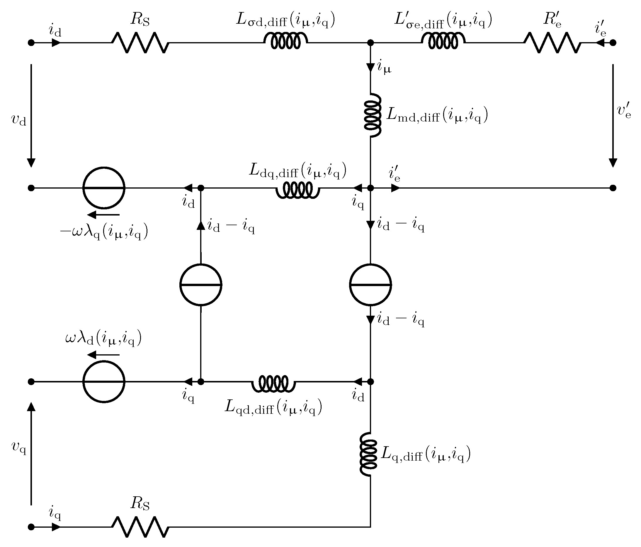
2.1. Modeling the EESM in dq-Frame

The EESM is modeled in a dq reference frame with the d-axis in the direction of rotor flux and the q-axis rectangular to the d-axis (quadrature component). Due to this definition, the rotor’s electrical excitation is on the d-axis. In the following, the voltage equation of the EESM and the modeling as T-Equivalent Circuit (EC) are derived shortly. A detailed description is given in [23] (also considering saturation) and [16,24].
With Clarke and Park transformation, the three-phase EESM phase voltages vabc and phase currents iabc are transformed in dq-axis voltages vd, vq and currents id, iq, while the stator phase resistance is RS. The inductance in the d-axis is divided into leakage inductance Lσd,diff and main inductance Lmd,diff, while in the q-axis both parts are combined in Lq,diff = Lσq,diff + Lmq,diff. Saturation is considered. Hence, inductances are given as differential inductances, and the values depend on the current. The induced voltages in the dq-frame rely on the flux linkages λd, λq and the electrical angular velocity ω.
The effective transformation ratio aeff is defined as the ratio of mutual inductance from the rotor to stator d-axis Lde and d-axis main inductance Lmd,abs
a eff = L md , abs L de .
Hence, the excitation current ie, voltage ve and excitation resistance Re are referred with aeff to the stator to referred excitation current i e , referred excitation voltage v e and referred excitation resistance R e . The excitation inductance is also divided into leakage and main inductance. They are referred to the stator as excitation leakage inductance L σ e , diff and main inductance Lmd,diff.
This results in the voltage equation
( v d v q v e ) = ( R S 0 0 0 R S 0 0 0 R e ) ( i d i q i e ) + ( L d , diff L dq , diff L md , diff L qd , diff L q , diff 0 L md , diff 0 L e , diff ) ( d i d d t d i q d t d i e d t ) + ( 0 ω 0 ω 0 0 0 0 0 ) ( λ d λ q λ e ) ,
with
L e , diff = 2 3 a eff 2 L e , diff R e = 2 3 a eff 2 R e i e = i e a eff v e = 2 3 a eff v e L d , diff = L dd , diff + L md , diff .
Combining the currents id and i e in the magnetization current iµ, the equation can be drawn as T-EC, see Figure 2.
Flux linkages can be determined with the absolute inductances Ld,abs and Lq,abs to
λ d = L d , abs i d + L md , abs i e + L dq , abs i q λ q = L q , abs i q + L qd , abs i d .
The calculation of the electrical torque Tel is derived from Lorentz force in the dq-frame with the number of pole pairs p to
T el = 1.5 p ( λ d i q λ q i d ) = 1.5 p ( L md , abs i e i q interaction + ( L d , abs L q , abs ) i d i q reluctance ) .
The torque is divided by its cause into interaction and reluctance torque: the interaction torque results from the magnetic flux generated from the rotor and stator; the reluctance torque results only from the flux from the stator.

2.2. Determination of the Effective Turns Ratio

The effective turns ratio aeff is necessary for modeling EESMs in T-EC and a specific parameter of EESMs. It is often determined from measurements by shortening the stator windings, see [23,25].
aeff is defined as the ratio of mutual inductance from the rotor to stator d-axis and Lde and d-axis main inductance Lmd,abs, see (3). Breaking this equation down to the definition of stator and rotor winding leads to
a eff = m 2 K W , S N S , coil a coils , ser 2 a coils , par Stator 1 K W , R N R , coil Rotor ,
with the number of phases m, number of windings per coils of stator NS,coil and rotor NR,coil, fundamental winding factor of the stator Kw,S and of the rotor Kw,R. A series connection of rotor coils is typical and assumed. For the stator, the number of series-connected coils acoils,ser and parallel groups acoils,par is considered.
The stator winding factor is determined by series expansion and is well-known in the literature. The calculation of the rotor winding factor is described in the following subsection.

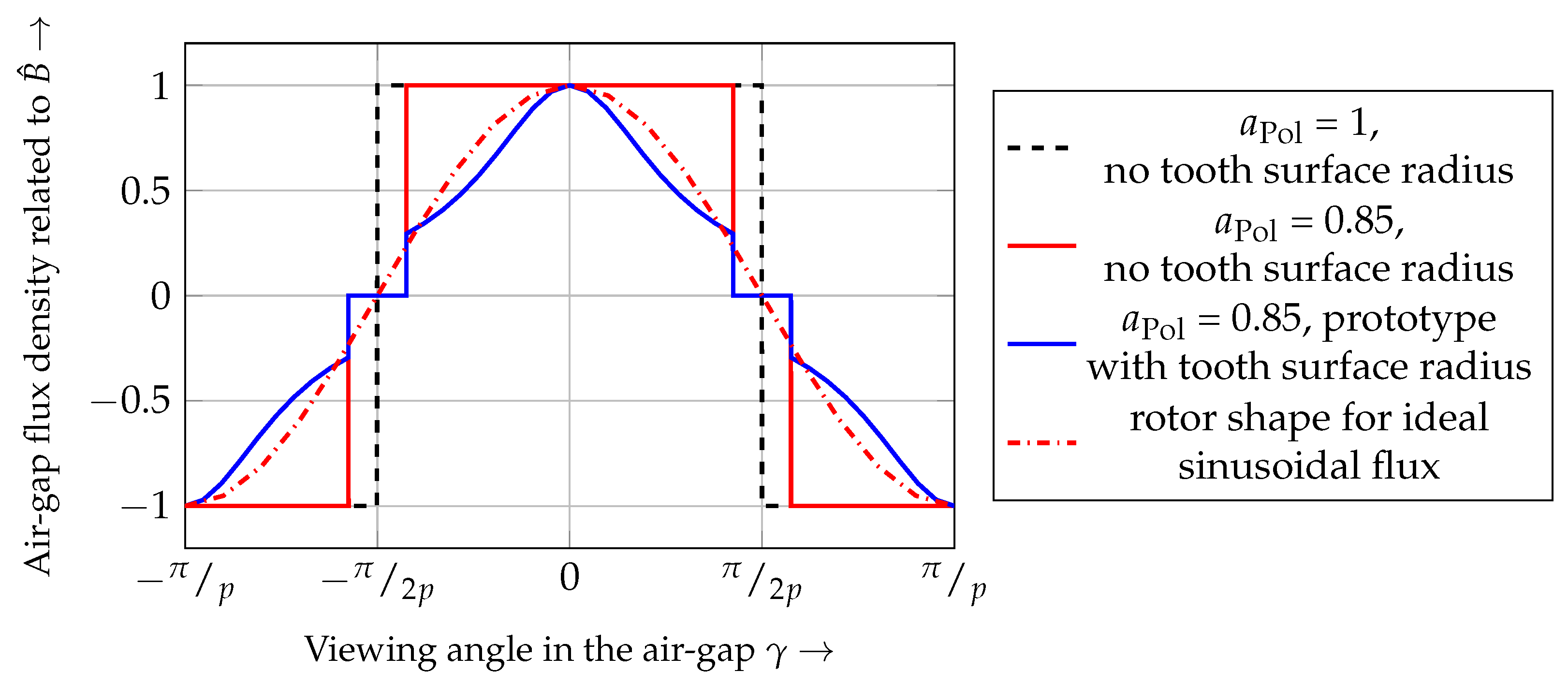
2.3. Rotor Winding Factor

Ref. [25] presented an approach of an analytical determination of rotor winding factor for EESMs with constant air-gap. In the following, a more detailed calculation method for rotor winding factor Kw,R is derived, considering variable air-gap and rotor slot opening. The rotor winding factor and the stator winding are calculated with the series expansion of the air-gap flux density. The influence of the saturation as well as flux leakage is neglected.
A constant air-gap and an ideal maximum pole width results in a perfect rectangular air-gap flux density; see the blue dashed line in Figure 3. This results in the fundamental winding factor of 1, the maximum winding factor. This geometry is not feasible for classical winding methods (a slot is needed) and has high harmonics. For ideal rectangular air-gap flux density, the 5th is 20%, and the 7th is 14.2% of fundamental winding factor, which results in high torque ripple (due to Y-wiring, the third harmonic is suppressed).
Considering the pole covering factor aPol, the winding factors are calculated with
K W , R , v = { sin ( v a Pol π 2 v )         for   v = 1 , 3 , 5 , 0   for   v = 2 , 4 , 6 , .
The air-gap flux density for a pole covering factor of aPol = 0.85 is plotted in Figure 3. The fundamental winding factor is decreased to about 2.8%.
An additional rounding of the rotor tooth is used for the prototype machine to reduce especially the fifth harmonic. In Figure 4, an example of the rounded tooth shape is shown, and geometric variables are defined. A higher tooth rounding, as used for the prototype, is drawn to highlight the effect of the rounding. The viewing angle-dependent γ magnetic air-gap length δ is determined with the pole offset height hPo, the diameter of the pole surface DR,Ps, and the stator inner diameter DS,in as
δ ( γ ) = h Po 2 + D S , in 2 4 h Po D S , in cos ( γ ) D R , Ps 2 ,
using the law of cosine.
With a series expansion, the odd winding factors Kw,R,ν, with the indexing variable ν = 2, 4, …, are determined with
K W , R , v = 0 π 2 p a Pol p δ cos ( ν p γ ) h Po 2 + D S , in 2 4 h Po D S , in cos ( γ ) D R , Ps 2 d γ ,
while all even factors are zero. The equation cannot be simplified further. The analytically determined air-gap flux density for the prototype machine is plotted in Figure 3. The fundamental winding factor decreases to 0.696, but the fifth harmonic is decreased to 4.3% of the fundamental winding factor. This directly reduces torque ripple.
An academic approach for an ideal sinusoidal air-gap flux density is presented in [26] (p. 170ff). Considering the pole covering factor, the fundamental winding factor is determined with
K w , R = 1 4 ( π a Pol + sin ( π a Pol ) ) .
All even harmonics are zero and all odd harmonics ν = 3, 5, … are calculated with
K w , R ( v ) = v   cos ( 0.5 π a Pol ) sin ( 0.5 π v a Pol ) v 2 1 sin ( 0.5 π a Pol ) cos ( 0.5 π v a Pol ) v 2 1 .
The air-gap flux density is plotted in Figure 3 for aPol = 1.

3. Optimization for Field Weakening

In this section, the influence of the rotor shape on high efficiency in field weakening is shown.

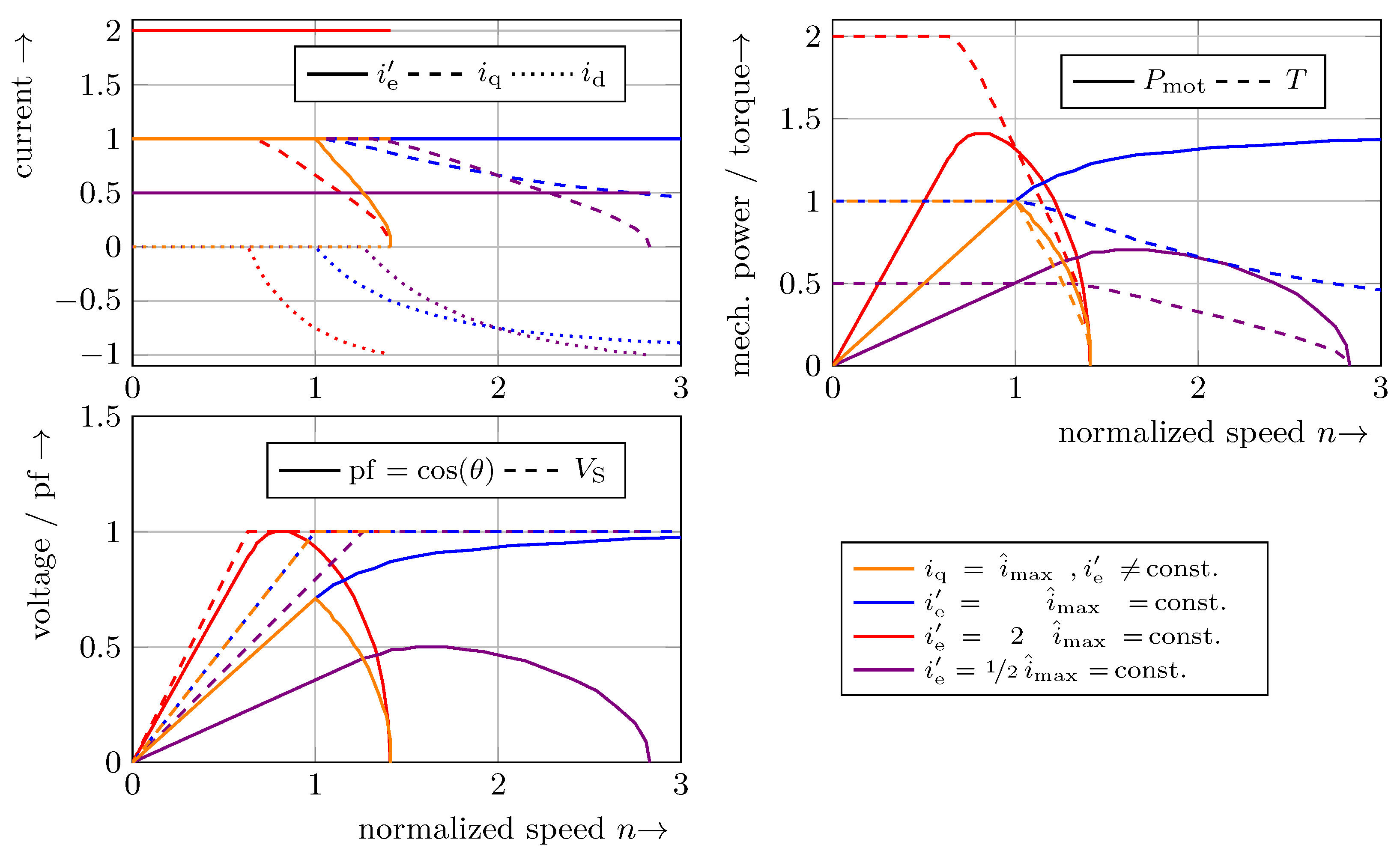
3.1. Operation of EESMs in Field Weakening

There are several operation strategies for EESMs. The most popular ones are Maximum Torque Per Ampere (MTPA), where the copper losses are reduced, and Maximum Efficiency (ME), where the overall losses of the machine are reduced, including iron losses. Due to the excitation current, there is one additional degree of freedom for EESMs compared to PMSMs. Hence, MTPA needs an additional condition to be solvable. Ref. [27] shows several possibilities for an analytic determination neglecting iron saturation. For applications with high power and torque density, such as traction drives for EVs, the impact of saturation has to be considered. Hence, a model with current-dependent Lookup tables (LUTs) for the inductances has to be used and numerically solved. A simplified approach is used below to highlight the principles and opportunities for influence.
Field weakening is the operation at the stator voltage limit v ^ max which leads to
v ^ max = v d 2 + v q 2 .
Considering stationary operation and neglecting the resistances, (4) is simplified with (6) into
( v ^ max ω ) 2 = λ d 2 + λ q 2 = ( L d , abs i d + L md , abs i e ) 2 + L q , abs 2 i q 2 .
For simplification, the analysis is conducted for a rotor without saliency (L = Ld,abs = Lq,abs). The leakage flux (Lmd,abs = Ld,abs = L) is neglected because the purpose is to look at and explain the principle of field weakening of EESMs. With this supposition, the voltage equation results in
( v ^ max ω ) 2 = L 2 ( i d + i e ) 2 + L 2 i q 2 ( v ^ max ω L ) 2 = ( i d + i e ) 2 + i q 2 .
With (7), the output power, considering the previously shown simplifications, is determined with
P mot = 2 π T n = 1.5 ω L i q i e .

3.1.1. Field Weakening by Reducing the Excitation Current

An evident opportunity for achieving field weakening for EESMs is the reduction in the rotor current. However, this is not the optimal solution since the field weakening is limited, as derived below.
For a rotor without saliency, there is no reluctance torque. Hence, id = 0 and iq = i ^ max in base speed. When the voltage limit is reached, the (referred) excitation current i e has to be reduced. The excitation current depending on the electrical frequency ω = 2πn is derived with (16) into
i e ( ω ) = v ^ max 2 L 2 ω 2 i q 2     i d     = 0 = v ^ max 2 L 2 ω 2 i ^ max 2 .
This condition inserted in (17) leads to
P mot = 1.5 i ^ max v ^ max 2 i ^ max 2 L 2 ω 2 .
The output power Pmot is zero for v ^ max2 = i ^ max2L2ω2, which results in the maximum speed of
n max = v ^ max 2 π L i ^ max .
As a result, field weakening due to the reduction in the excitation current leads to limited field weakening and a non-constant power in field weakening. In Figure 5, currents, torque, power and voltage are plotted over speed. The variables are related to the corner point (operation point, where the voltage limit is reached with maximum stator current and referred excitation current i e = i ^ max). In addition, the bottom graph also shows the power factor (pf). With the method of reducing the excitation current, the power factor decreases significantly in field weakening.

3.1.2. Field Weakening by Negative d-Axis Current

The other opportunity to achieve field weakening is to weaken the field from the stator. This is achieved with a negative d-axis current id. With (16) the d-axis current depending on the electrical frequency ω is derived into
i d ( ω ) = v ^ max 2 L 2 ω 2 i q 2 i e .
The stator current is set to i ^ max = i d 2 + i q 2 to achieve maximum torque. This results in a speed-depended q-axis current to
i q ( ω ) = i ^ max 2 i d 2 ( ω ) = i ^ max 2 ( v ^ max 2 L 2 ω 2 i q 2 i e ) 2 .
In the following, a closer look at the case i e = i ^ max is taken, which can be reduced. The common case will be considered numerically later. This condition leads to
i q ( ω ) = v ^ max 4 i ^ max 2 L 2 ω 2 v ^ max 2 2 i ^ max L 2 ω 2
and is combined with (17) to obtain
P mot ( ω ) = 1.5 v ^ max 2 L 4 i ^ max 2 L 2 v ^ max 2 ω 2 .
The first finding is that for high speed, the power is constant:
P mot ( ω ) ω = 1.5 i ^ max v ^ max .
Secondly, the power is increasing until |ω| v ^ max.
This behavior is good for machines with a wide field weakening area, such as traction motors for EVs.
In Figure 5, the currents, torque, power, voltage and power factor are plotted over speed. The variables are related to their value at the corner point. The blue line shows the result for the previously derived optimal condition: i e = i ^ max = const. and i d 2 + i q 2 = i ^ max. It can be shown that the power factor also increases in field weakening. Hence, the maximum power in field weakening is higher than at the corner point.
As an example, the conditions i e = 2 i ^ max = const. (red) and i e = 1 2 i ^ max = const. (purple) are plotted. With higher excitation current, the torque and power in base speed can be increased, but the field weakening is strongly limited. Reduced excitation current can increase the field weakening, but output power is reduced, and field weakening is also limited. In both cases, the power factor increases in field weakening. All shown evaluations are conducted without the consideration of any losses. The iron, bearing and air friction losses are highly speed-dependent for real machines. Hence, the output power decreases at a certain speed, and the maximum speed is limited. Nevertheless, the shown conditions regarding power factor and maximum theoretical speed apply.

3.1.3. Conditions for Infinite Field Weakening

In sum, the current triple for constant power in field weakening is calculated with
i e = i ^ max i q = ( v ^ max L ω ) 2 1 4 i ^ max 2 ( v ^ max L ω ) 4 i d = i ^ max 2 i q 2 .
The finding of this derivation is that, even when the rotor flux is adjustable, a negative d-axis current is necessary to reach constant power in field weakening. For real machines, d-axis and q-axis inductances are different. The rotor of EESMs is most salient due to the winding on the rotor tooth. Hence, typically Ld,abs > Lq,abs. Combing torque calculation (7) with the current definition in field weakening (25) leads to a negative reluctance torque
( L d , abs L q , abs ) > 0       i q     > 0       i d     < 0 < 0 .
In summary, d-axis inductance should be smaller than q-axis inductance
L d , abs < L q , abs .
Another result is that in field weakening operation the referred rotor current i e is in the range of the stator current i ^ —especially at the maximum characteristic. The analytical calculation of aeff, presented in Section 2, is helpful in the design process. Due to flux leakage, nonlinearity and various loss effects, i e does not necessarily need to be the same as i ^ for optimal operation (e.g., maximum efficiency operation).
Ref. [23] shows that this also has a positive effect on the operation below field weakening. Due to the saturation, the negative d-axis current desaturates the main inductance Lmd,abs. It leads to an increase in interaction torque.

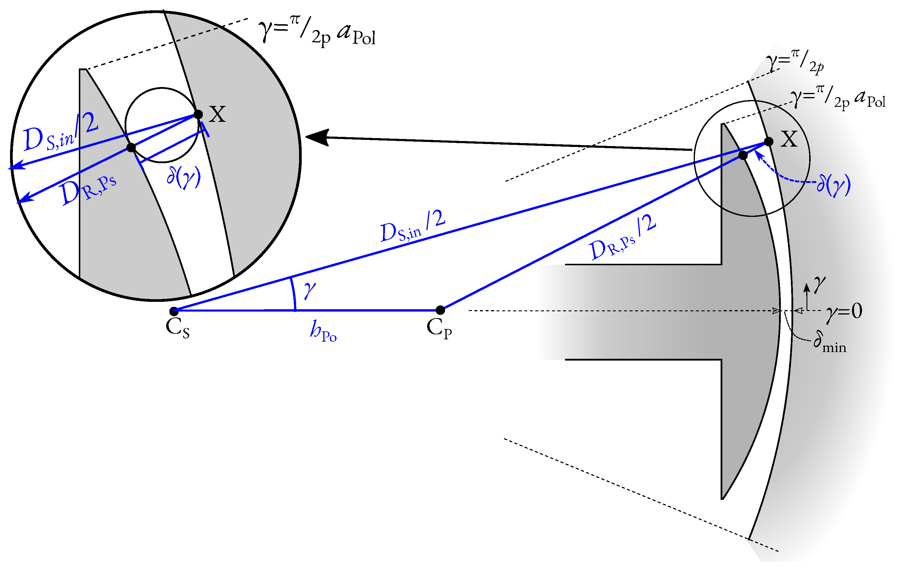
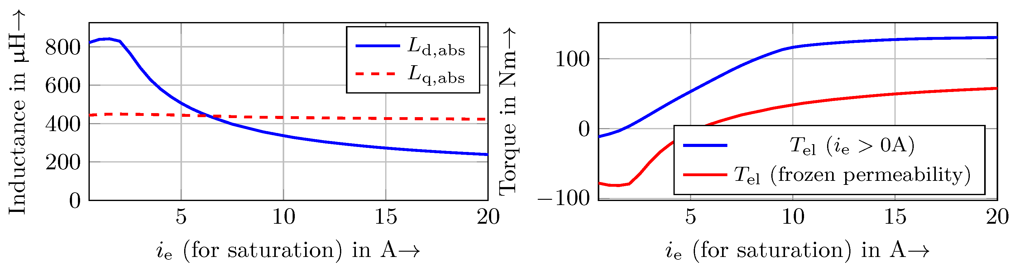
3.2. Rotor Design for Ld,abs < Lq,abs

As previously described, the condition Ld,abs < Lq,abs is suitable to achieve high efficiency in field weakening as well as in operation with high torque (due to saturation). Due to the rotor winding, d-axis inductance is typically higher than q-axis inductance for EESMs. In the following, it is shown that this ratio can be turned due to the saturation in the rotor. Therefore, a closer look at the rotor flux density is taken. The frozen permeability method is used to divide the flux into its cause. It is a pure theoretical method to explain the influence of different magnetic sources on a saturated magnetic part, see [28,29]. The permeability from one simulation is “frozen” and used for another simulation.
Simulations with rotor current but without stator current are used to determine the permeability. The permeability in the rotor yoke (marked with blue in Figure 6a) is then used for a simulation with only stator current. The current is set to iq = −id = 150 A. With this combination, it is expected that the ratio of Ld,abs to Lq,abs can be displayed as
Ld,abs > Lq,abs the main flux path is in d-axis direction;
Ld,absLq,abs flux path is approximately halved into d-axis and q-axis direction;
Ld,abs < Lq,abs the main flux path is in q-axis direction.
Due to the low excitation current in Figure 6b, the permeability of the rotor yoke is high, and the main flux path is through the rotor yoke. This means that the main flux path is in the d-axis direction, and hence, Ld,abs > Lq,abs. The excitation current in Figure 6c is chosen to picture the region where Ld,absLq,abs. It can be seen that there is no clear main path. The flux path is divided into one part through the rotor yoke (d-axis direction) and one part which dives only into the tooth tip and exits the tooth near the q-axis. In Figure 6d, the excitation current is further increased. The main part of the magnetic flux shortens the rotor from the d-axis directly into the q-axis. The amount of stator flux through the rotor yoke is low. In this case, Ld,abs < Lq,abs. In Figure 7, the inductances and torque depending on ie are plotted. The results agree with the description of Figure 6. At approximately ie = 5.5–6 A, Lq,abs is higher than Ld,abs and torque-determined only with stator current is becoming positive. It is also evident that for ie < 2 A, the torque is negative, even if the rotor excitation is considered.
In summary, the d-axis inductance could be smaller than Lq,abs, even for EESMs. The rotor tooth has to be designed so that the yoke and tooth (d-axis flux path) are saturating in a wide range of ie. The simulations are performed with the build-up prototype. It is designed for a maximum excitation current of ie = 20 A. Above a current of ie ≈ 5 A, the rotor yoke saturates and Ld,abs is smaller than Lq,abs. This is achieved due to a bottleneck for the rotor tooth’s magnetic flux, which starts to saturate first; see Figure 6c. Second, the yoke saturates; see Figure 6d. Additionally, the tooth tip width has to be high (small slot) to increase Lq,abs. The above requirements are unfavorable for the mechanical strength of the tooth. Hence, EESMs often have a high tooth width and rotor yoke to increase mechanical strength, especially in generator designs. Therefore, the mechanical strength of the design machine is analyzed before manufacturing the prototype.

4. Electromagnetic Optimization of the Machine Parts

This section shows the electromagnetic optimization of the EESM. An operation point-dependent optimization method for EESM is developed and applied to an EESM as traction drive for a medium-sized EV. The goal is to optimize the 2D design of the electromagnetic parts.

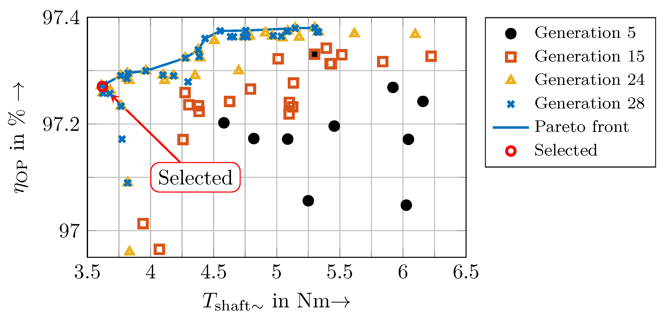
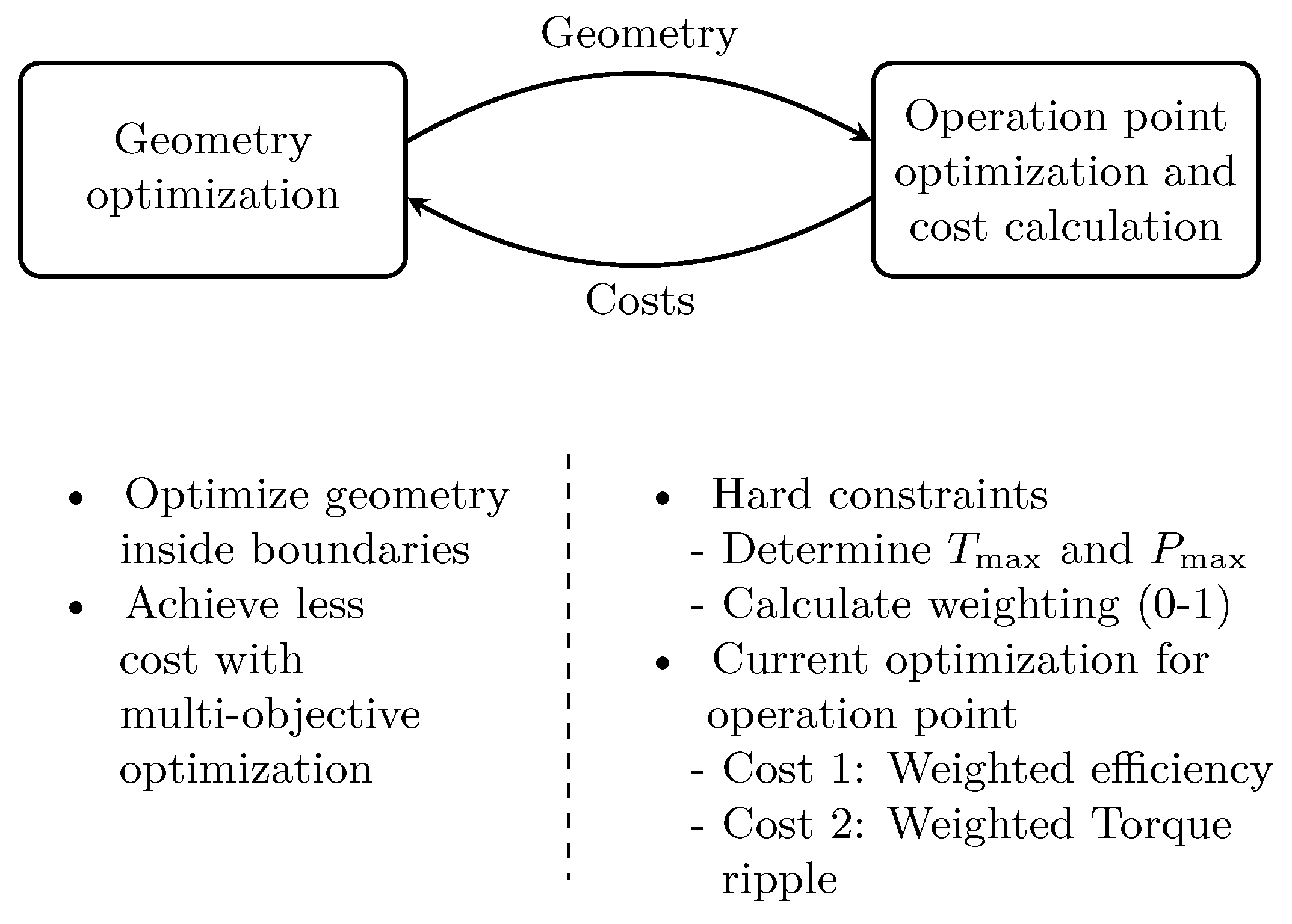
4.1. Optimization Method

For the optimization, two optimizations are nested, as shown in Figure 8. The outer optimization is the geometry optimization. A multi-objective Non-Dominated Sorting Genetic Algorithm (NSGA) is used to vary the geometry and find the best solution. The costs are calculated for each individual, generated with NSGA. The optimization goal is to achieve high efficiency at one operation point (even several operation points are possible) and to reduce torque ripple for this operation point. Furthermore, there are a few hard constraints that have to be fulfilled. At first, the hard constraints are verified. Therefore, MTPA with maximum current is solved numerically by combining the analytical model shown previously and Finite Element Analysis (FEA). To reduce simulation time, at first, one FEA is solved with iq = i ^ max and ie = ie,max and the inductances are derived. With these inductances, MTPA is solved with the analytical model. The resulting current combination is used for another FEA, and the analytical modeling is repeated. For the applied optimization, less than five FEA are sufficient to determine MTPA with the maximum current. The rated point is selected due to the voltage limit with simulated inductances. Power and torque are compared with hard constraints.
Next, the efficiency of the operation point is determined. This also requires an optimization of the current triple. A combined analytical model and FEA is used. Furthermore, less than five FEAs are necessary to determine efficiency. Iron losses are neglected in calculating the currents but are considered in the efficiency. Besides efficiency, torque ripple in the operation point is determined.
The resulting costs (efficiency and torque ripple) are weighted due to the hard constraints. If an individual is far from the constraints, costs calculation aborts before operation point optimization, and the worst value for the cost is submitted. If the constraints are nearly reached, efficiency in the operation point is determined, but both costs are weighted. Hence, efficiency is reduced, and torque ripple is increased.

4.2. Applied Optimization

The requirements and boundary conditions are derived from the BMW i3 as reference EV. The main requirement is to achieve the same operating range as the PMSM used in the i3. Furthermore, the electrical conditions are the same. Due to the construction and manufacturing, the outer diameter, active length and the number of pole pairs are fixed. The optimization goal is to achieve high efficiency, especially for medium-to-high speed in partial load. As RP, an operation point with 40 Nm at 9000 rpm was chosen. The optimization’s main boundary conditions and goals are listed in Table 1.
The optimization results for torque ripple and efficiency are shown in Figure 9. As an example, the results for the 5th, 15th, 24th and 28th generation are plotted. The blue line shows the Pareto front (no individual achieves lower costs for both cost functions). From 5th to 12th and also to 24th, the individuals become better. For the 5th and 12th generations, the individuals achieve either high efficiency or low torque ripple. With the 24th generation, both can be achieved. Simulation is aborted after the 28th generation because results could not be improved significantly. The marked individual is chosen for the prototype due to low torque ripple Tshaft~ and good efficiency ηOP. The efficiency could not be increased significantly. The result seems robust because several individuals achieve similar results.

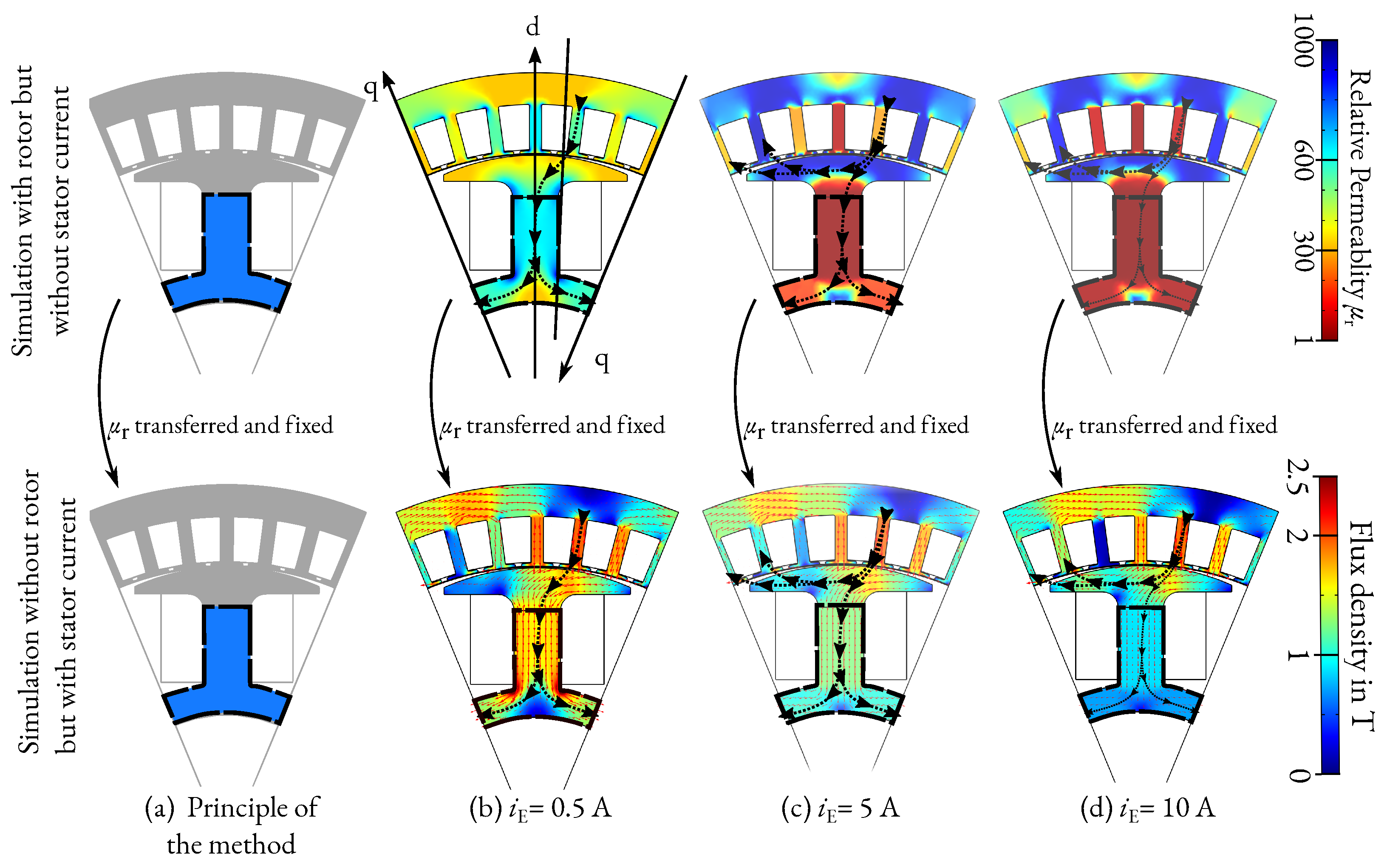
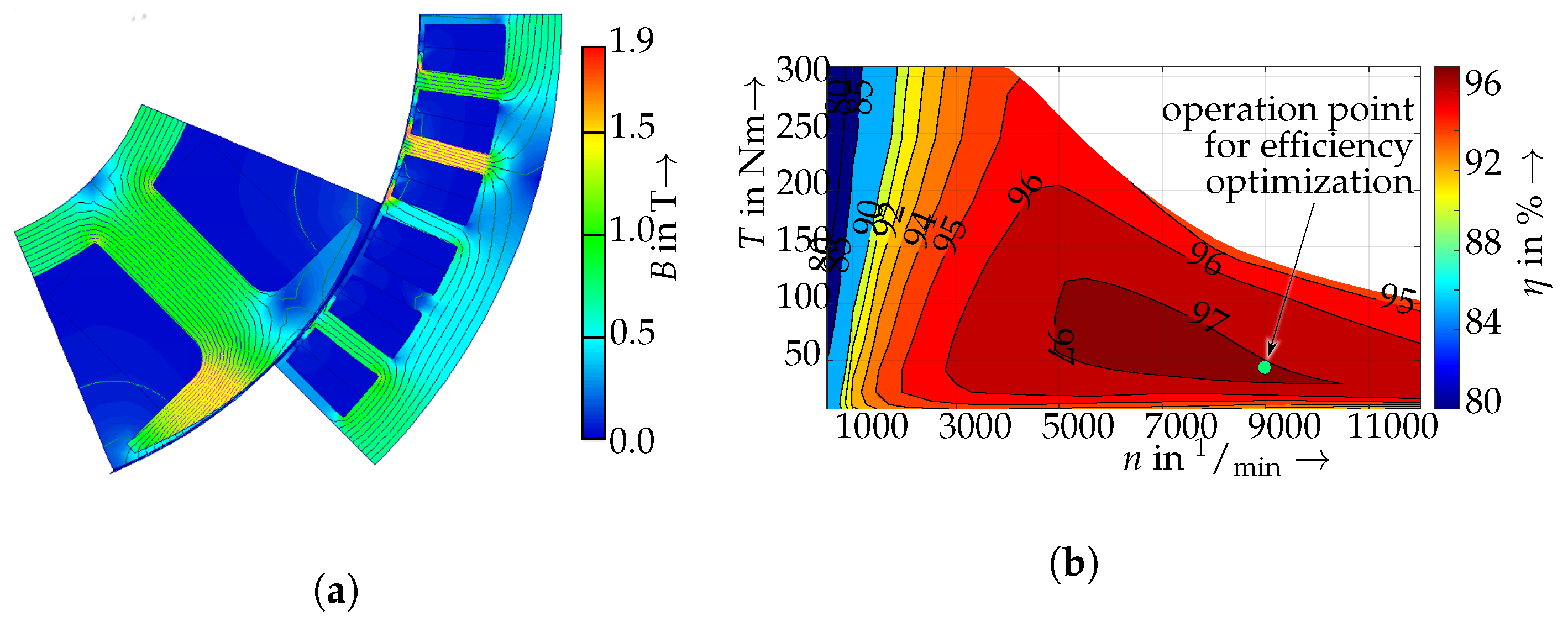
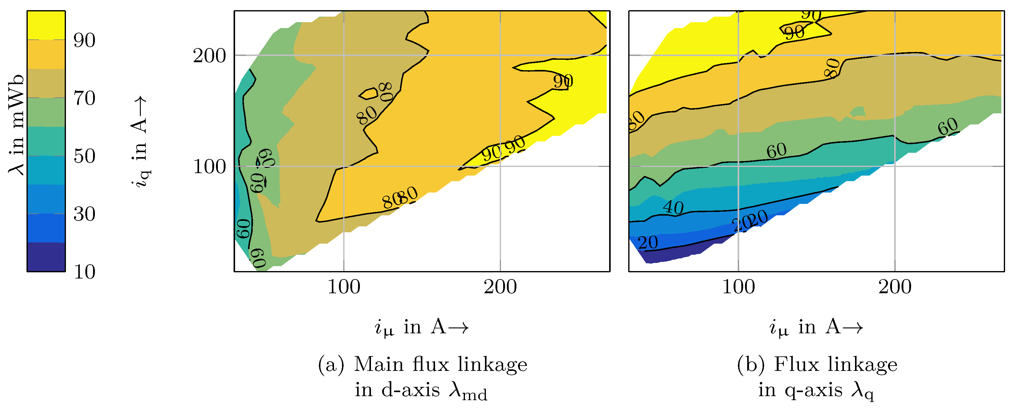
4.3. Electromagnetic Simulation of the Finalized Geometry

In Figure 10a, the flux density of the prototype machine at the optimization point (40 Nm@9000 rpm) is shown. This operation point is in partial load and field weakening. The flux density is about 1 T and becomes more saturated for higher torque.
The complete simulated efficiency map for the prototype machine is shown in Figure 10b. The representative point is marked. During optimization, efficiency at this point is increased. This point is in the area of maximum efficiency of >97%. The region with efficiency >97% extends from 5000 rpm up to 9500 rpm and up to 50% of maximum torque (at 7000 rpm). As the mechanical losses are neglected, it is to be expected that the measured efficiency is slightly lower. The influence of the mechanical losses depends on the speed. The effect on efficiency is higher at low-to-medium loads than at high loads. Due to the fact that mechanical losses cannot be optimized with the active parts, neglecting mechanical losses is permissible for optimizing the electromagnetic parts.

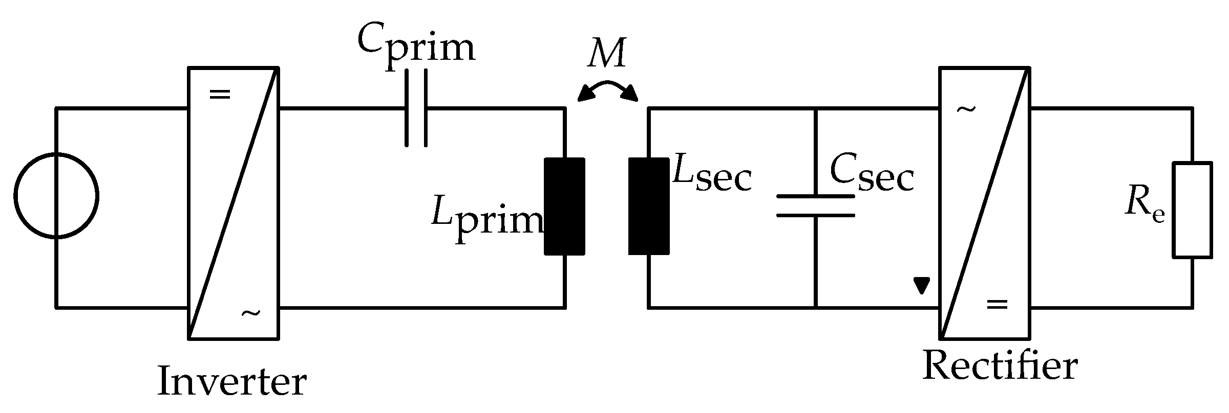
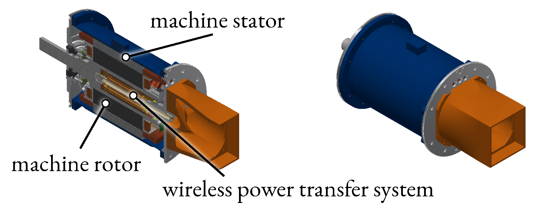
5. Design of the WPT System

For the WPT system, a both-sides compensated system is used to achieve a good efficiency. The equivalent circuit is shown in Figure 11. On the primary side, the compensation (Cprim) is in series to the inductance (Lprim). On the secondary side, the compensation (Csec) is parallel to the inductance (Lsec). M is the mutual inductance between (Lprim) and (Lsec). The system is driven with a DC source on the primary side.
The system is designed according to [30], the topologies are described in [15]. For the operation of the WPT system, a full bridge inverter is used on the primary side and a half bridge active rectifier is used on the secondary side. With the both-sides compensated system and the active rectifier, a maximum efficiency of more than 95% of the WPT system is achieved in the best operating point. The efficiency includes the losses of the inverter and rectifier, but it neglects the losses in the variable voltage source, which is used to control the rotor current. The WPT system has a wide operating area due to the temperature-depending rotor resistance. The system is designed so that the maximum efficiency is reached at higher rotor resistances to reduce the losses in the hot operating points.

6. Construction of the Prototype

This section describes the construction of the iEESM as a complete system. It starts with the WPT placement of the WPT. Next, the design of the rotor is shown and ends with the construction of the complete iEESM. An excerpt of the prototype’s parameters is listed in Table 2.

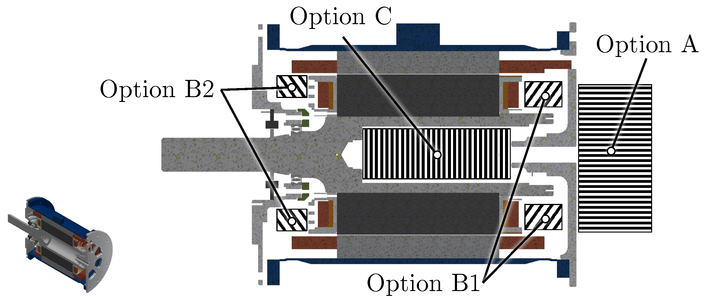
6.1. Placement of the WPT

Figure 12 shows the possibilities for the placement of the WPT system. The Drive End (D.E.) of the machine is on the left side and the Non-Drive End (N.D.E.) on the right side.
Option A (outside on the N.D.E.) is predestinated to replace slip rings of an EESM and is used in [15,16]. The additional space compared to PMSMs and the need for one or two bearings in the WPT system are disadvantageous.
Option B (Inside beneath the stator end windings) is often used in current publications [9,10,15,16,32]. Typically, variant B1 with the transmission on the N.D.E. is used because no torque is transmitted on this side. It is also easier to mount and contact. In most cases, this side is the one with the floating bearing. Hence, the manufacturing tolerances and thermal expansion have to be considered in the design process of the WPT system. Furthermore, air cooling for the rotor winding has to be considered. This can be a challenge for rotationally symmetric systems.
Option C (inside the shaft) is a novel option invented during the development of the presented iEESM. The placement of an energy transmission system inside the hollow shaft is patented in [33,34]. The WPT system is integrated into the machine shaft. The advantage is that spare space is used, and the dimensions of the complete system iEESM only depend on the machine parts. The requirement is that the diameter of the rotor is correspondingly large. The space in the hollow shaft must be sufficient for the transmission system. In this option, the WPT system does not influence a rotor winding air cooling. In turn, the cooling of the WPT system must be considered.
The WPT system has to be designed with an outer rotating secondary side fixed and mounted inside the shaft. The stationary primary side is placed on a rod or tube inside the secondary side.

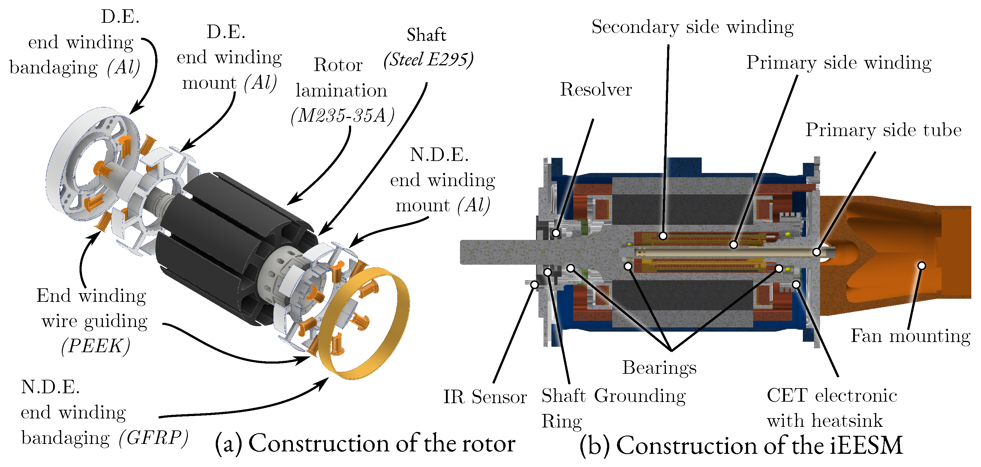
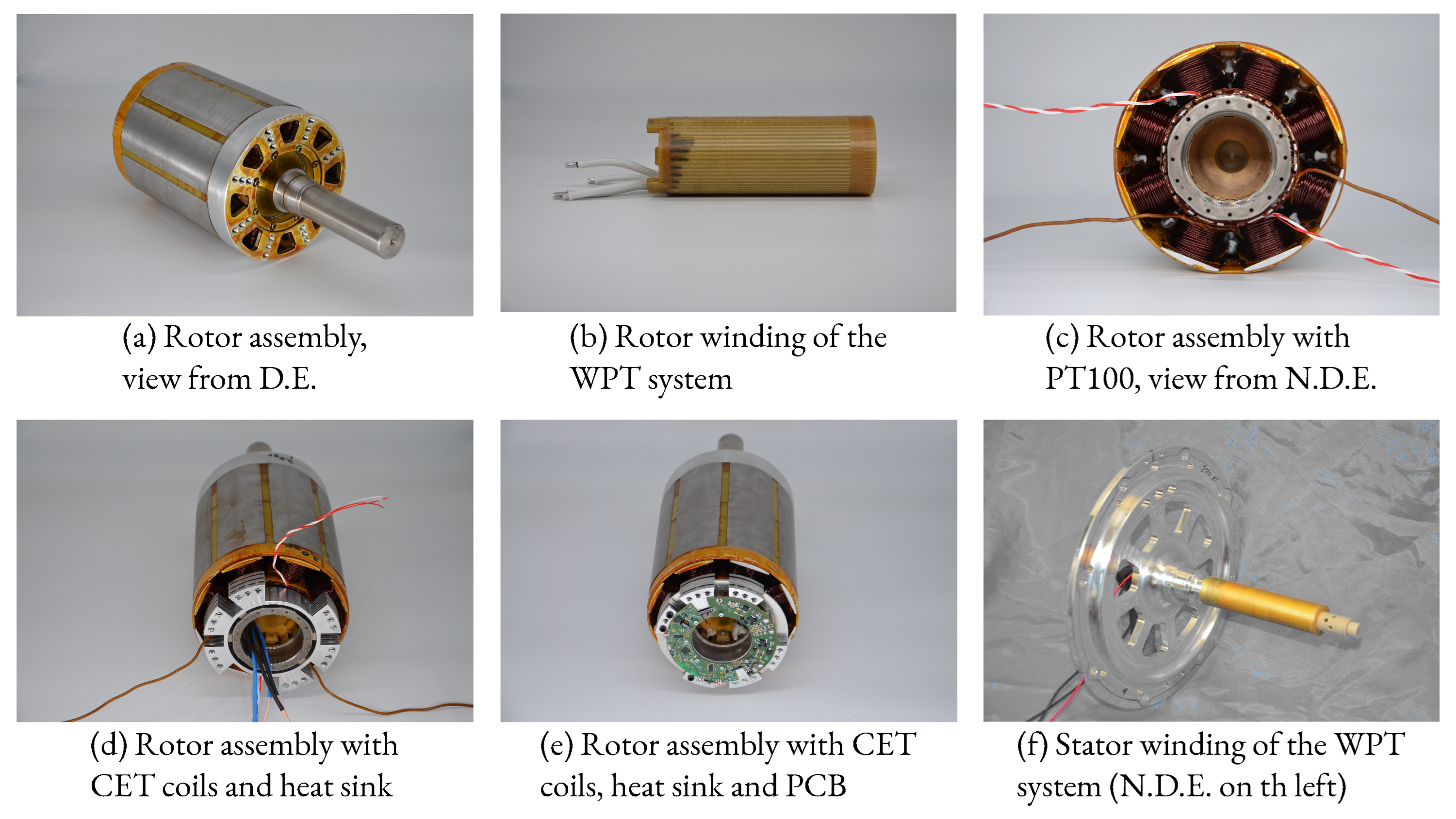
6.2. Rotor Construction

Figure 13a shows the rotor construction of the machine parts. Several parts increase the mechanical strength of winding and end winding. An aluminum end winding mount is added directly to the electrical sheet on both sides. Teeth are covered with a PEEK end winding wire guiding. Hence, the first layer of rotor winding is guided to receive proper winding. The end winding mount on D.E. is bandaged with an aluminum star. Due to the WPT, electronics mounted on N.D.E., a Glass-Fiber Reinforced Plastic (GFRP) is used on that side. For winding fixation, a GFRP wedge is added into the slot after wounding, and the complete rotor is impregnated with a resin.
Figure 14 shows the integration of the WPT system for the prototype.

6.3. iEESM Construction

Figure 13 is a cross-section of the complete system in an axial direction. The rotor is mounted inside the stator with two bearings. A shaft grounding is added on the D.E. to avoid bearing currents. As a position sensor, a four-pole resolver is used. For rotor temperature measurement, Infrared (IR) sensors sense rotor end winding temperature from the stator. The WPT stator consists of a wound PEEK tube that could be cooled with compressed air. Alternatively, the primary side could be redesigned for water coolant. On the N.D.E., the fan for ventilation is mounted with a 3D-printed part.

7. Prototype, Control and Measurement
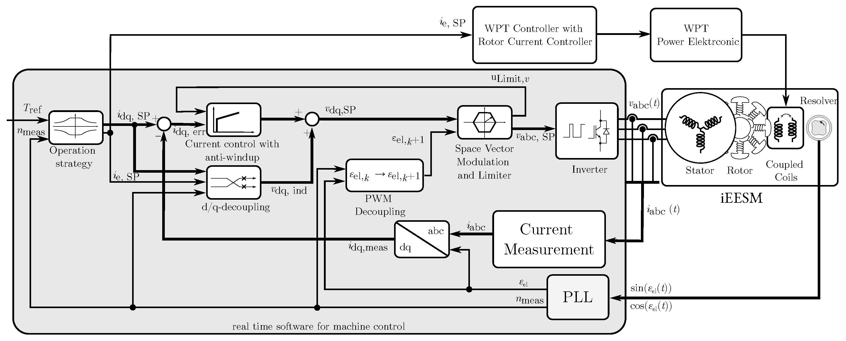
This section describes the control of the iEESM, the test bench setup and measurement results.

7.1. Control

Figure 15 gives an overview of the control system of the iEESM.
The input variable for the machine control is the reference torque Tref. The operation strategy defines the speed-dependent setpoint currents for stator idq,SP and rotor ie,SP. The induced voltages vdq,ind for decoupling the d- and q-axis are calculated with setpoint currents and measured speed. Subtracting measured stator current idq,meas from idq,SP results in the current error idq,err and is one input for the current controller. The second input is a flag to enable anti-windup if the voltage limit is reached. If the voltage limit is reached, integration is stopped. The current controller is realized as a PI controller. The addition of the output from the current controller and induced voltages results in setpoint voltages vdq,SP. They are transformed into three-phase Pulse Width Modulation (PWM) signals vabc,SP with space vector modulation and the estimated electrical angle of the next time step εel,k+1. The PWM signals are input for the inverter to result in the physical three-phase voltages vabc(t). The second output from space vector modulation is a flag to indicate whether the voltage limit is reached to start the anti-windup method. The three-phase currents iabc(t) are measured and transformed into dq-currents idq,meas. The electrical angle εel and speed nmeas are measured with the resolver and determined with a Phase-Locked Loop (PLL).

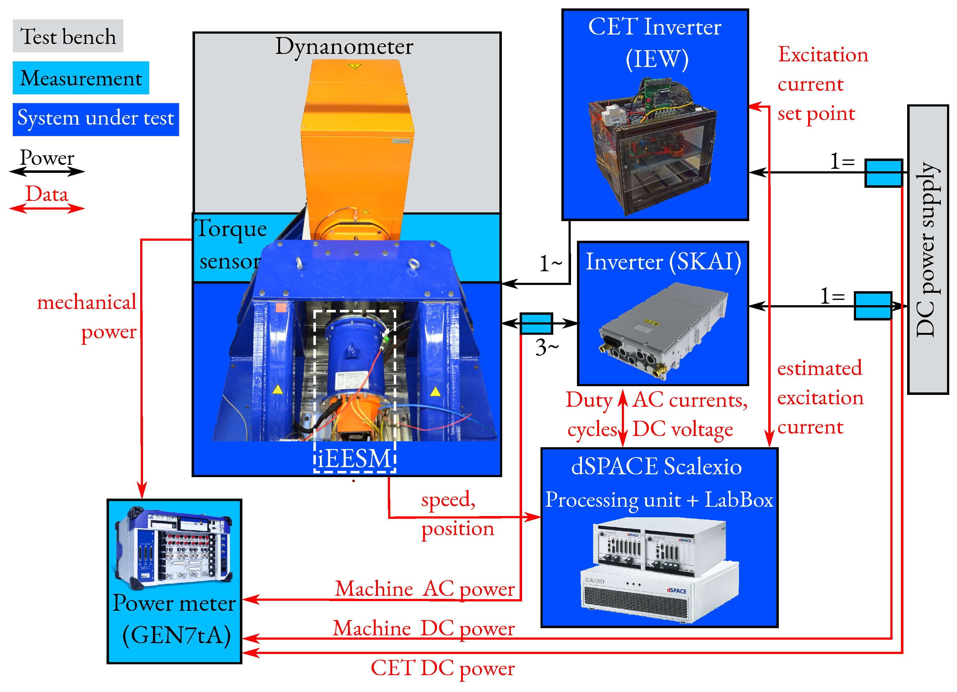
7.2. Test Bench Setup

Figure 16 shows the setup on the test bench at the Institute of Electrical Energy Conversion (IEW). The test bench is driven speed-controlled, and the iEESM is torque-controlled. The power is measured with HBM’s power meter GEN7tA. The machine is operated with Semicron’s three-phase voltage source inverter SKAI 45 A2 GD12-WQI. Except for the current measurement, the inverter used is the same as [35]. dSPACE’s scalexio system is used to realize the control system, consisting of a processing unit and a LabBox (for IOs).

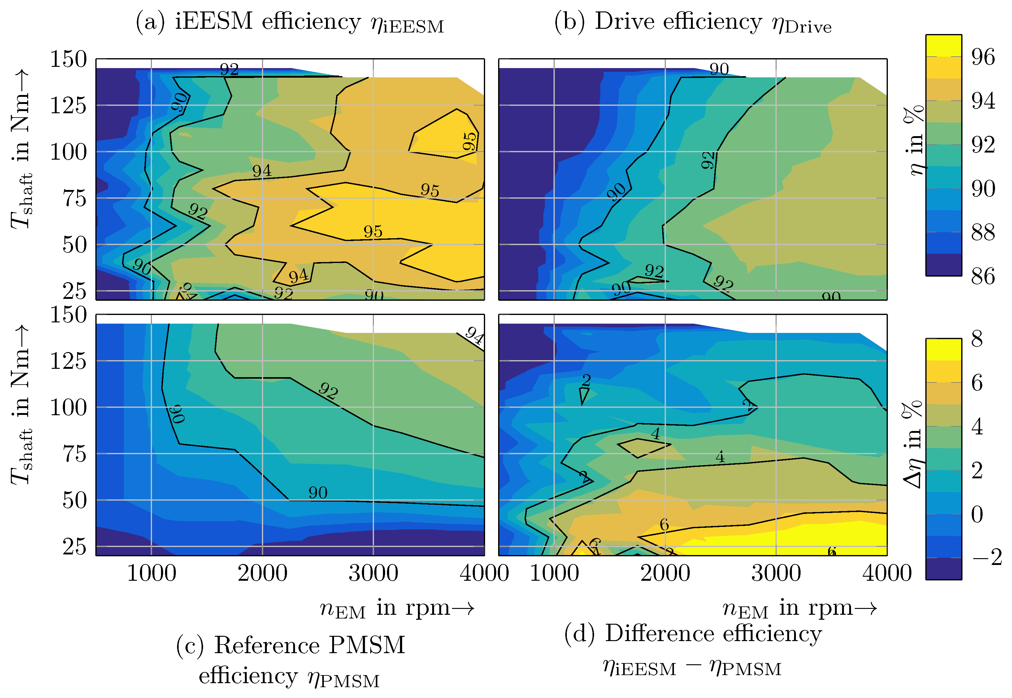
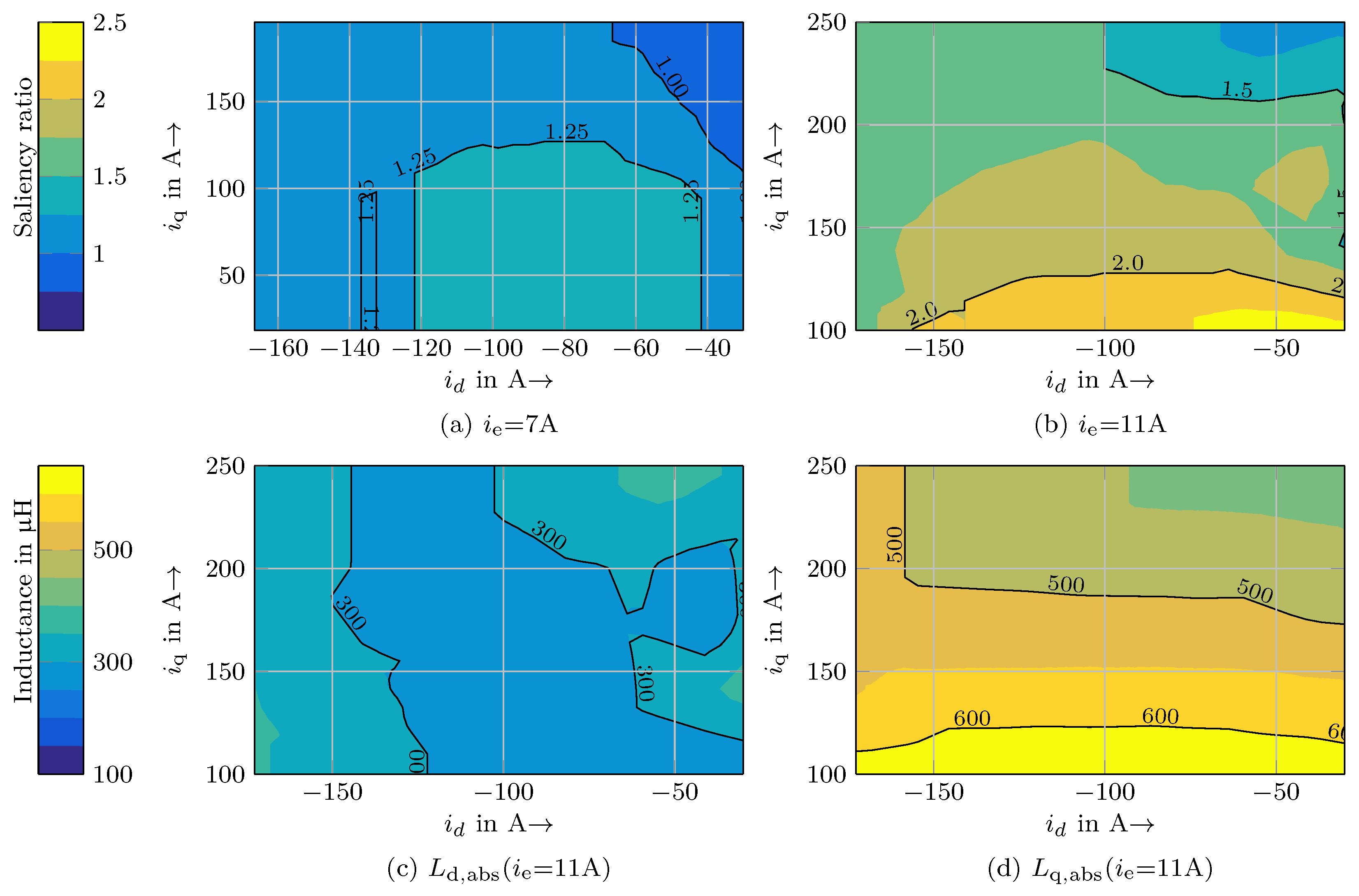
7.3. Measurement Results

The measurements are taken at static load with constant temperature (stator copper temperature 50–70 °C, temperature of the rotor winding and WPT coil system 70–90 °C).
In Figure 17, the measured flux linkage maps are plotted over magnetization current iµ and q-current iq. Regarding Section 2, the number of measured operation points is reduced significantly. Only id-ie-combinations with positive magnetization current iµ are measured because negative magnetization is irrelevant. Furthermore, operation points with low q-current iq and high magnetization current iµ are not optimal. Hence, only operation points with iq/iµ ≥ 0.5 are measured.
The saliency ratio Lq,abs/Ld,abs is plotted as an example for ie = 7 A and ie = 11 A in Figure 18a,b. It shows that for both excitation currents, the q-axis inductance is greater than the d-axis inductance (Ld,abs < Lq,abs, saliency ratio ≥1) for most current combinations. As described in Section 2, this positively impacts the efficiency of field weakening operation. A maximum saliency ratio of 2.5 is achieved. The saliency ratio increases with the excitation current. This is consistent with the theoretical investigations and the optimization shown in this work. Additionally, in Figure 18c,d, the measured absolute inductances Ld,abs and Lq,abs are visualized. Lq,abs is mainly depended on iq while Ld,abs is more or less constant. The d-axis inductance is mainly saturated due to the excitation current ie = 11 A (maximum is ie = 20 A).
The measured efficiency with the operation strategy MTPA is shown in Figure 19. Highest efficiency is in partial load 50–100 Nm for 2500–4000 rpm. The efficiency of the iEESM is more than 92% for speed above 1500 rpm. The maximum efficiency for the entire drive (including the machine inverter) is 92.5% in a wide range above 2500 rpm.
The measurements are compared with the results of BMW’s i3 PMSM of [31]. The efficiency of the iEESM is higher in nearly all operation points and is more than 4 percentage points higher for a broad region. As expected, the efficiency difference is at its maximum in partial load.
In Table 3, selected measurement results are listed. The effective turns ratio is determined with short circuit measurements with different excitation currents (as described in [23]).

8. Conclusions

This publication presents the process of designing, modeling, optimizing, constructing and measurement of an iEESM.
The system iEESM consists of the machine part for torque generation and the wireless power transmission onto the rotor. It is designed for use in an EV. For the reference vehicle, BMW’s i3 was chosen. A wide operating range is therefore required. In particular, the part-load zone is relevant for high efficiency in the drive cycle and an extended vehicle range.
Hence, this work focused on the design of the iEESM in field weakening and high integration of the WPT. The WPT is placed inside the hollow shaft, reducing the necessary space for the system. The rotor is designed to achieve positive reluctance torque with negative d-axis current. This work argues that this is necessary for operation in field weakening with a wide constant power range. It is proven with measurements of the inductances. The measurement results of the efficiency of the iEESM were compared with the measurements of the i3’s PMSM. The efficiency is significantly increased by about 4 percentage points in a wide operation range and up to 8 percentage points in single operation points.

9. Patents

Two patents result from this work, see [33,34].

Author Contributions

Conceptualization, software and validation, S.M. and D.M.; methodology, software, validation of the machine parts and validation of the complete system, S.M.; methodology, software and validation of the wireless power transmission system, D.M.; supervision and discussion, S.M., D.M, and N.P. All authors have read and agreed to the published version of the manuscript.

Funding

The research leading to this publication has received funding from the Vector Stiftung in Stuttgart. https://www.vector-stiftung.de/ (accessed on 4 February 2023).

Data Availability Statement

Not applicable.

Conflicts of Interest

The authors declare no conflict of interest.

Abbreviations

The following abbreviations are used in this manuscript:
BMWBayerische Motoren Werke AG
D.E.Drive End
ECEquivalent Circuit
EESMElectrically Excited Synchronous Machine
EMElectrical Machine
EVElectrical Vehicle
FEAFinite Element Analysis
GFRPGlass-Fiber Reinforced Plastic
iEESMInductive Electrically Excited Synchronous Machine
IMInduction Machine
IRInfrared
LUTLookUp Table
MEMaximum Effciency
MTPAMaximum Torque Per Ampere
N.D.E.Non-Drive End
NSGANon-Dominated Sorting Genetic Algorithm
PLLPhase-Locked Loop
PMASRPermanent Magnet-Assisted Synchronous Reluctance Motor
PMSMPermanent Magnet Synchronous Machine
PWMPulse Width Modulation
RPRepresentative Point
WLTCWorldwide Harmonized Light Vehicles Test Cycle
WPTWireless Power Transfer

References

  1. Wayland, M. Auto Executives Say More than Half of U.S. Car Sales Will Be EVs by 2030, KPMG Survey Shows. Available online: https://www.cnbc.com/2021/11/30/auto-executives-say-more-than-half-of-us-car-sales-will-be-evs-by-2030-kpmg-survey-shows.html (accessed on 11 April 2022).
  2. Gül, T.; Tattini, J.; Pales, A.F. Global EV Outlook 2021. Available online: https://www.iea.org/reports/global-ev-outlook-2021/trends-and-developments-in-electric-vehicle-markets (accessed on 11 April 2022).
  3. Trading Economics. Price Trend of Neodymium. Available online: tradingeconomics.com/commodity/neodymium (accessed on 29 April 2022).
  4. Bailey, G.; Mancheri, N.; van Acker, K. Sustainability of Permanent Rare Earth Magnet Motors in (H)EV Industry. J. Sustain. Metall. 2017, 3, 611–626. [Google Scholar] [CrossRef]
  5. Carraro, E.; Morandin, M.; Bianchi, N. Optimization of a traction PMASR motor according to a given driving cycle. In Proceedings of the 2014 IEEE Transportation Electrification Conference and Expo (ITEC), Dearborn, MI, USA, 15–18 June 2014; pp. 1–6. [Google Scholar] [CrossRef]
  6. Grundmann, D.; Gneiting, A.; Fischer, J.M.; Parspour, N. Design and Optimization of a Quadruple 3-Phase Permanent Magnet Assisted Synchronous Reluctance Machine. In Proceedings of the IECON 2021—47th Annual Conference of the IEEE Industrial Electronics Society, Toronto, ON, Canada, 13–16 October 2021; pp. 1–6. [Google Scholar] [CrossRef]
  7. Mike Duff. BMW Brings the Electric HEAT: BMW EESM. Available online: https://www.caranddriver.com/news/a22656237/bmw-simplifies-ev-production/ (accessed on 4 February 2023).
  8. Tang, J.; Liu, Y.; Sharma, N. Modeling and Experimental Verification of High-Frequency Inductive Brushless Exciter for Electrically Excited Synchronous Machines. IEEE Trans. Ind. Appl. 2019, 55, 4613–4623. [Google Scholar] [CrossRef]
  9. Tang, J. Design and Control of Electrically Excited Synchronous Machines for Vehicle Applications. Ph.D. Thesis, Chalmers University of Technology, Gothenburg, Sweden, 2021. [Google Scholar]
  10. Illiano, E.M. Design of a Highly Efficient Brushless Current Excited Synchronous Motor for Automotive Purposes. Ph.D. Thesis, ETH Zurich, Zurich, Switzerland, 2014. [Google Scholar] [CrossRef]
  11. Stancu, C.; Ward, T.; Rahman, K.M.; Dawsey, R.; Savagian, P. Separately Excited Synchronous Motor With Rotary Transformer for Hybrid Vehicle Application. IEEE Trans. Ind. Appl. 2018, 54, 223–232. [Google Scholar] [CrossRef]
  12. Krupp, H.; Mertens, A. Rotary Transformer Design for Brushless Electrically Excited Synchronous Machines. In Proceedings of the 2015 IEEE Vehicle Power and Propulsion Conference (VPPC), Montreal, QC, Canada, 19–22 October 2015; IEEE: Piscataway, NJ, USA, 2015; pp. 1–6. [Google Scholar] [CrossRef]
  13. Weber, J.N.; Rehfeldt, A.; Vip, S.A.; Ponick, B. Rotary transformer with electrical steel core for brushless excitation of synchronous machines. In Proceedings of the 2016 XXII International Conference on Electrical Machines (ICEM), Lausanne, Switzerland, 4–7 September 2016; pp. 884–889. [Google Scholar] [CrossRef]
  14. Maier, M.; Parspour, N.; Kleemann, P.; Hagl, M. Construction and measurements of an electrical excited synchronous machine with inductive contactless energy transfer to the rotor. In Proceedings of the 2017 Brazilian Power Electronics Conference (COBEP), Juiz de Fora, Brazil, 19–22 November 2017; pp. 1–6. [Google Scholar] [CrossRef]
  15. Maier, D.; Kurz, J.; Parspour, N. Contactless Energy Transfer for Inductive Electrically Excited Synchronous Machines. In Proceedings of the 2019 IEEE PELS Workshop on Emerging Technologies: Wireless Power Transfer (WoW), London, UK, 18–21 June 2019; pp. 191–195. [Google Scholar] [CrossRef]
  16. Maier, M. Betrieb Einer Elektrisch Erregten Synchronmaschine Mittels Kontaktloser, Induktiver Energieübertragung auf den Rotor, 1st ed.; Berichte aus dem Institut für Elektrische Energiewandlung; Shaker: Düren, Germany, 2020; Volume 11. [Google Scholar]
  17. Gunther, S.; Ulbrich, S.; Hofmann, W. Driving cycle-based design optimization of interior permanent magnet synchronous motor drives for electric vehicle application. In Proceedings of the International Symposium on Power Electronics, Electrical Drives, Automation and Motion (SPEEDAM), Ischia, Italy, 18–20 June 2014; IEEE: Piscataway, NJ, USA, 2014; pp. 25–30. [Google Scholar] [CrossRef]
  18. Pinhal, D.B.; Gerling, D. Driving Cycle Simulation of Wound-Rotor Synchronous Machine with Hairpin Windings Considering AC-Losses. In Proceedings of the 2019 IEEE Transportation Electrification Conference and Expo (ITEC), Detroit, MI, USA, 19–21 June 2019; pp. 1–7. [Google Scholar] [CrossRef]
  19. Salameh, M.; Brown, I.P.; Krishnamurthy, M. Fundamental Evaluation of Data Clustering Approaches for Driving Cycle-Based Machine Design Optimization. IEEE Trans. Transp. Electrif. 2019, 5, 1395–1405. [Google Scholar] [CrossRef]
  20. Lazari, P.; Wang, J.; Chen, L. A Computationally Efficient Design Technique for Electric-Vehicle Traction Machines. IEEE Trans. Ind. Appl. 2014, 50, 3203–3213. [Google Scholar] [CrossRef]
  21. Sarigiannidis, A.G.; Beniakar, M.E.; Kladas, A.G. Fast Adaptive Evolutionary PM Traction Motor Optimization Based on Electric Vehicle Drive Cycle. IEEE Trans. Veh. Technol. 2017, 66, 5762–5774. [Google Scholar] [CrossRef]
  22. Forster, D.; Inderka, R.B.; Gauterin, F. Data-Driven Identification of Characteristic Real-Driving Cycles Based on k-Means Clustering and Mixed-Integer Optimization. IEEE Trans. Veh. Technol. 2020, 69, 2398–2410. [Google Scholar] [CrossRef]
  23. Müller, S.; Parspour, N. Applying a Measurement-Based Iron Loss Model to an Efficiency Optimized Torque Control of an Electrically Excited Synchronous Machine. In Proceedings of the 2020 International Conference on Electrical Machines (ICEM), Gothenburg, Sweden, 23–26 August 2020; pp. 779–785. [Google Scholar] [CrossRef]
  24. Schröder, D. Elektrische Antriebe—Regelung von Antriebssystemen, 4. auflage ed.; Springer Vieweg: Berlin/Heidelberg, Germany, 2015. [Google Scholar] [CrossRef]
  25. Grune, R. Verlustoptimaler Betrieb Einer Elektrisch Erregten Synchronmaschine für den Einsatz in Elektrofahrzeugen. Ph.D Thesis, Technische Universtität Berlin, Berlin, Germany, 2012. [Google Scholar]
  26. Richter, R. Allgemeine Berechnungungselemente: Die Gleichstrommaschine; Julius Springer: Berlin/Heidelberg, Germany, 1924; Volume 1. [Google Scholar]
  27. Haala, O.; Wagner, B.; Hofmann, M.; März, M. Optimal current control of externally excited synchronous machines in automotive traction drive applications. Int. J. Electr. Comput. Energetic Electron. Commun. Eng. 2013, 7, 1133–1139. [Google Scholar]
  28. Bianchi, N. Electrical Machine Analysis Using Finite Elements; Power Electronics and Applications Series; CRC Press: Boca Raton, FL, USA, 2005. [Google Scholar]
  29. Schmidt, E.; Susic, M. Parameter evaluation of permanent magnet synchronous machines with tooth coil windings using the frozen permeabilities method with the finite element analyses. In Proceedings of the 2012 25th IEEE Canadian Conference on Electrical and Computer Engineering (CCECE), Montreal, QC, Canada, 29 April–2 May 2012; pp. 1–5. [Google Scholar] [CrossRef]
  30. Maier, D.; Heinrich, J.; Zimmer, M.; Maier, M.; Parspour, N. Contribution to the System Design of Contactless Energy Transfer Systems. IEEE Trans. Ind. Appl. 2019, 55, 316–326. [Google Scholar] [CrossRef]
  31. Ozpineci, B. FY2016 Electric Drive Technologies Annual Progress Report; EERE Publication and Product Library: Washington, DC, USA, 2016. [Google Scholar] [CrossRef]
  32. MAHLE. MAHLE Develops Highly Efficient Magnet-Free Electric Motor. Available online: https://www.mahle.com/en/news-and-press/press-releases/mahle-develops-highly-efficient-magnet-free-electric-motor--82368 (accessed on 2 October 2021).
  33. Maier, D.; Müller, S.; Parspour, N. Elektrisch erregte Maschine und Anordnung für eine elektrisch erregte Maschine. German Pantent DE102020207000A1, 4 June 2020. [Google Scholar]
  34. Maier, D.; Müller, S.; Parspour, N. Elektrisch erregte Maschine und Anordnung für eine elektrisch erregte Maschine. European Union Patent EP3920385A1, 4 June 2021. [Google Scholar]
  35. Semikron. SKAI 45 A2 GD12-WDI. Available online: https://www.semikron-danfoss.com/de/produkte/produktklassen/systeme/detail/skai-45-a2-gd12-wdi-14282032.html (accessed on 30 January 2023).
Figure 1. CAD model of the integrated inductive electrically excited synchronous machine.
Energies 16 01657 g001
Figure 2. Dynamic equivalent electrical circuit in dq frame for EESMs.
Energies 16 01657 g002
Figure 3. Air-gap flux density for different rotor shapes.
Energies 16 01657 g003
Figure 4. Sketch of a rotor tooth with additional radius with the parameters: rotor pole covering factor aPol, air-gap height δ, pole offset hPo, rotor pole surface diameter DR,Ps, stator inner diameter DS,in.
Energies 16 01657 g004
Figure 5. Influence of field weakening on electrical and mechanical quantities over speed for different field weakening approaches. Upper plot shows the influences on current, the middle plot on output power and torque and the bottom plot shows speed-dependent voltage and power factor. The color indicates the discussed method (see upper legend), and the line style indicates the quantity (shown in the legend in each plot). The quantities are related to its value on the corner point for the first approach ( i e = i ^ max = const.). For all approaches, the magnitude of the stator current is maximum ( i ^ max). All losses are neglected.
Energies 16 01657 g005
Figure 6. Simulation with frozen permeability method for different excitation currents. (a) Shows the principle of the method: simulations on the top are performed without stator current. The permeability in the marked region is frozen and used for the simulation with stator but without rotor current. (bd) Shows the permeability of the iron without stator current (left) and the resulting flux density considering stator current (iq = −id = 150 A, ie = 0 A). On the bottom side, the flux density vector is plotted in red. Additionally, the preferred flux paths are highlighted with black arrows.
Energies 16 01657 g006
Figure 7. Inductances over excitation current ie determined with frozen permeability method. The bottom figure shows torque with and without excitation current. Stator current is set to iq = −id = 150 A for all simulations.
Energies 16 01657 g007
Figure 8. Overview of the nested optimization.
Energies 16 01657 g008
Figure 9. Optimization results; selected geometry for prototype is highlighted.
Energies 16 01657 g009
Figure 10. Simulation results of the optimized machine. (a) Flux density for prototype machine for 40 Nm@9000 rpm, (b) Simulated efficiency map for prototype machine considering copper and iron losses.
Energies 16 01657 g010
Figure 11. Equivalent circuit of the WPT system.
Energies 16 01657 g011
Figure 12. Possibilities for placement of the WPT system.
Energies 16 01657 g012
Figure 13. Mechanical design of the rotor (a) and the complete iEESM (b) in a cross-sectional view.
Energies 16 01657 g013
Figure 14. Integration of the WPT system of the prototype at different manufacturing states.
Energies 16 01657 g014
Figure 15. Real-time software for machine control (highlighted in gray) with in- and outputs. Big arrows are vectors with multiple signals; small arrows show single signals.
Energies 16 01657 g015
Figure 16. Test bench setup.
Energies 16 01657 g016
Figure 17. Measured flux linkages at 2000 rpm.
Energies 16 01657 g017
Figure 18. (a,b) Saliency ratio Lq,abs/Ld,abs exemplary for two constant excitation currents, (c,d) absolute inductances Ld,abs and Lq,abs for ie = 11 A.
Energies 16 01657 g018
Figure 19. (a,b) measured efficiency with operation strategy MTPA on the test bench, (c) results from reference PMSM [31], (d) difference in efficiency ηiEESMηPMSM.
Energies 16 01657 g019
Table 1. Main conditions for optimization.
RequirementsOperation Point Optimization
Rated torque150 NmSpeed9000 rpm
Maximum torque>250 NmTorque40 Nm
Rated speed4800 rpmMachine efficiencymaximize
Maximum speed11,400 rpmTorque rippleminimize
Table 2. Parameters of the prototype and the BMW i3.
PrototypeBMW i3 [31]
Number of pole pairsp4 6
Stator outer diameterDS,out230mm242mm
Rotor outer diameterDR,o179mm179mm
Stack lengthlstack180mm132mm
Magnetic air-gap lengthδ0.5mm0.5mm
Number of stator slotsQS48 72
Tshaft for line peak current 530 A310Nm250Nm
Torque density at maximum torque point41.4kNm/m341.1kNm/m3
Table 3. Measurement results.
Efficiency iEESM 50–75 Nm@2500–4000 rpm95%
Efficiency of reference PMSM for 50–75 Nm@2500–4000 rpm90–92% [31]
iEESM linearized inductance Ld,abs (ie) = 11 A≈300 mH
iEESM linearized inductance Lq,abs (ie)≈600 mH
iEESM effective turns ratio 1 18.6 = 0.0538
Disclaimer/Publisher’s Note: The statements, opinions and data contained in all publications are solely those of the individual author(s) and contributor(s) and not of MDPI and/or the editor(s). MDPI and/or the editor(s) disclaim responsibility for any injury to people or property resulting from any ideas, methods, instructions or products referred to in the content.

