Article

On-Line Monitoring of Shunt Capacitor Bank Based on Relay Protection Device

1
School of Electrical and Electronic Engineering, North China Electric Power University, Beijing 102206, China
2
State Grid Tangshan Power Supply Company, Tangshan 063000, China
*
Author to whom correspondence should be addressed.
Energies 2023, 16(4), 1615; https://doi.org/10.3390/en16041615
Submission received: 15 November 2022 / Revised: 31 January 2023 / Accepted: 3 February 2023 / Published: 6 February 2023

Abstract

:
In modern power systems, the installation of a shunt capacitor bank is one of the cheapest and most widely used methods for improving the voltage profile. One shunt capacitor bank is composed of mass capacitor units and have ground, ungrounded, delta, wye connections that make configuration of capacitor banks is various. In the case of long-term operation, the failure of a single capacitor unit of a capacitor bank is likely to cause uneven voltage, which will lead to the breakdown and burning of the whole group, resulting in huge losses. The relay protection device can detect the simultaneous voltage and current of the capacitor. By utilizing these data from the relay, the abnormal state of the shunt capacitor banks at the initial stage of the fault can be found through monitoring the slight change in capacitance. Timely and early maintenance and repair would avoid capacitor bank faults and potentially greater economic losses. Capacitor banks have different connection modes. For ungrounded wye-connected capacitor banks with an unknown neutral point voltage, the capacitance parameters of each branch cannot be calculated. A parameter symmetry based on the calculation method for capacitor parameters is proposed. For long-term monitoring and observation of the capacitor capacitance value, the fault state and abnormal state of the capacitor are identified based on statistical methods. The simulation established by PSCAD verified that a relay protection device can realized an effective monitoring of the early abnormal state of the capacitor bank.

1. Introduction

In the modern power system, capacitors are widely used in energy storage, voltage regulation, filtering and other scenarios due to their simple structure and limited manufacturing and maintenance costs [1]. As a reactive power supply, shunt capacitors can adjust the system voltage, improve the power quality and reduce the line loss [2]. As their implementation has increased, shunt capacitor banks have become one of the power devices with the highest failure rate. Faults in capacitor banks have caused group explosions and group damage many times [3,4], resulting in significant fluctuations in grid voltage, increasing active and reactive power losses, reducing the service life of capacitors and compromising the safety of the power grid.
The literature includes a great deal of in-depth research on the use of protection and monitoring technology of shunt capacitors to improve reliability and reduce losses. The most common means of protecting capacitors is to use different connection and voltage levels, with an emphasis on configuration protection [5,6,7,8,9,10,11,12] References [5,6] at the 500 kV voltage level, parallel compensation of substations and lines and series compensation capacitors. In addition, the protection of these capacitors is analyzed in detail, and the optimal protection configurations and scheme setting principles are given for each type of capacitor. Reference [7] calculates and analyzes the sensitivity and settings of relay protection under the various modes of the shunt capacitor banks in the 1000 kV ultra-high voltage (UHV) power system in China. Reference [8] introduces the setting principle for unbalanced protection of the H-bridge high-voltage capacitor banks. These methods provide excellent protection, but the specialized protection design and settings need to be based on different voltage levels and wiring forms, which are more complicated and costly; these need to be studied separately according to the actual working conditions of the system. Another research method relies on the development of smart substations to realize the monitoring function of shunt capacitors [13,14,15,16]. The capacitor fault monitoring system in [13] extracts synchronous voltage and current signals through specialized devices to monitor shunt capacitor banks in real time, which requires more space and is more costly. Reference [14] uses compensated negative sequence and neutral currents to locate internal faults and can locate faults that occur simultaneously in either of the two branches of a double-wye parallel capacitor bank. Reference [15] proposes a new scheme based on the unbalanced current at the neutral point. By calculating the unbalanced current distribution under all possible operating conditions, the fault severity and fault location can be identified. Reference [16] designs a very sensitive real-time capacitor-monitoring device based on calculating capacitance through the variation of LC oscillation frequency for early internal component failures of capacitor banks. This type of method mostly aims to design a dedicated monitoring device in an intelligent substation system that effectively reduce the high failure rate of capacitors and be highly universal.
Because the second method mentioned above is more economical and practical, this paper proposes a new monitoring method for shunt capacitors. The relay protection device installed on the bus can easily obtain the simultaneous voltage and branch current of the shunt capacitor bank (the voltage is equal to the bus voltage, and the branch current of the capacitor can be obtained from different CT taps). It will be very economical and convenient to only use this information to monitor the shunt capacitor banks. However, it has difficulty calculating the ungrounded wye configuration when there is no additional device to obtain the neutral voltage. In this case, the equations are solved by using the additional conditions of symmetric parameters of two branches and setting alarms according to guidelines and statistical methods that prevent capacitor faults and potential losses. An on-line monitoring method for shunt capacitor banks that is not affected by the connection method is constructed. The simulation verifies the effectiveness and feasibility of this method.

2. Principles of Shunt Capacitor Bank Monitoring

There are many types of shunt capacitor bank faults. When the internal capacitor fault is caused by overvoltage, harmonics, product defects, etc., the capacitance change value mostly occurs during the initial stage [17]. Factors such as overvoltage and harmonics cause abnormalities and failure of the individual capacitor unit in the internal series-parallel components. Damage to a single component compromises the operating state of other components; this situation gradually evolves and ultimately leads to the failure of the high-voltage shunt capacitors.
In the initial stage of capacitor fault, the abnormality of an individual unit of the shunt capacitor bank can be identified via variation in capacitance. The on-line monitoring method of the shunt capacitor bank can be realized based on the simultaneous voltage and current obtained by the relay protection device at the bus of the shunt capacitor [18].
The most common internal capacitor fault is the breakdown of internal capacitor units. There are three kinds of breakdown faults: electric breakdown, thermal breakdown and partial discharge breakdown. Electric breakdown is mainly due to the rapid breakdown of defective capacitors due to high voltage, high harmonics and other factors. Electric breakdown occurs over a short period of time, the relationship with environmental factors is small, maintenance cannot be performed in a timely manner and monitoring is of little significance. The other two kinds of breakdown develop gradually, which will produce a dielectric change before the breakdown fault. The fault can be found by measuring the capacitance.
According to the guide for the protection of shunt capacitor banks, there are three kinds of fuse protection: internal fuses, external fuses and fuseless. Internal fuses offer very effective protection. When a unit fails, the overcurrent causes the fuse to blow. If a single faulty unit is isolated, the shunt capacitor can continue to operate. However, if an internal fuse exhibits the failures shown in Figure 1b, the group capacitors with the faulty unit will be short-circuited, and the remaining capacitor groups will operate in overvoltage mode. Over a long period of time, a more serious fault would occur. Timely detection of changes can effectively avoid potential losses. If the faulty unit of an internal fuse is isolated as shown in Figure 1c, the shunt capacitor bank with a single faulty unit can still operate normally; the capacitance value changes, however, resulting in uneven voltage across the group. Long-term operation may also cause other unit faults, even serious failures. Timely detection and replacement of faulty parts can also effectively prevent the expansion of a fault.
To sum up, most internal capacitor faults undergo a long process of capacitance value change. This process is affected by environment, voltage level and other factors, and it is impossible to formulate unified rules for monitoring. However, the capacitor has been comprehensively inspected at the initial stage of installation and the failure rate is low; this will be taken as the normal state at this time. By storing the data at this time and comparing real-time data with statistical methods, it can be determined whether there is a significant change. If there is a significant change, the capacitor is considered abnormal. The statistical method is general, and the reference sample is its own normal state sample; it can therefore be applied to most of the shunt capacitor banks that operate for a long time (data support).
The connections in shunt capacitor banks are wye, delta and double-wye connections. The relay protection has the following types: Zero-sequence voltage protection performs well for shunt capacitor grounding faults. Differential protection applies to all capacitor external faults. Overcurrent protection is the basic protection for all types of capacitors [19]. Double-wye connection has extra overcurrent protection at the neutral point. This connection is also divided into two cases: ungrounded and grounded [20]. The voltage at both ends of the grounding capacitor is equal to the bus voltage. The capacitance value of each phase can then be calculated by obtaining the branch current [21]. However, an ungrounded capacitor cannot calculate the capacitance value in this way, as it requires additional equipment to extract the neutral point voltage. In this paper, no additional equipment is required for calculating the ungrounded shunt capacitor bank. The simultaneous voltage and current data from the bus are the only data used to calculate the capacitance value as the monitoring criterion for the capacitor bank.

2.1. The Method of Calculating Capacitance Value

The four most common configurations of a wye-connected capacitor bank are shown in Figure 2. The CT/PT of the relay protection is built on the bus. The grounded-connected line parameters can be can easily calculated based on three-phase voltage and current, after which the capacitance change can be observed via the change in the line parameters. The calculation of ungrounded-connected line parameters is needed to obtain the voltage of the neutral point. However, increase of PT circuits means more cost and lower reliability.
Ungrounded capacitor banks mainly consist of the wye and double-wye connections. Both wye and double-wye connections can be simplified as shown in Figure 1 [4]. We look at each phase capacitor as an impedance and we monitor its change. The change in the phase capacitance reflects the operating state of the capacitor. The advantage of monitoring the capacitance of the capacitor is that, compared with the unbalanced protection of the capacitor, the monitoring amount is the capacitance value, which is more intuitive and can better reflect the status of the capacitor. Compared with regular maintenance, monitoring is simpler and requires less time [22]. The capacitor circuit is equivalent to that shown in Figure 3, and the solution process is as follows:
An ungrounded double-wye connection can be simplified as shown in Figure 2. The ungrounded wye and delta connections can be simplified as shown in Figure 2c. U ˙ k   ( k = A , B , C ) and I ˙ k   ( k = A , B , C ) are the bus voltages and branch currents of the capacitors. Z ˙ A , Z ˙ B and Z ˙ C are the equivalent three-phase-impedance values, including parallel capacitors, line impedances and series reactors. The two-branch-current equation is shown in the following [23].
U ˙ A I ˙ A Z ˙ A = U ˙ B I ˙ B Z ˙ B U ˙ B I ˙ B Z ˙ B = U ˙ C I ˙ C Z ˙ B
Z ˙ A , Z ˙ B and Z ˙ C are unknown quantities. Because there are only two equations in Equation (1), it cannot be solved. An additional equation is therefore required to solve the equations.
In the normal state, the three-phase parameters are equal. In the case of a single-phase fault or abnormal state, the equivalent impedance of the two other normal phases are the same. In the case of a two-unit fault in a different phase, the same working condition, model and operating conditions are assumed, so that the changes of the two-phase faults are similar. In the case of a three-phase capacitor fault, the parameters remain approximately equal for the same reason. To sum up, the operating characteristic of capacitors is that at least two-phase have the same impedances. The shunt capacitor bank must have the same three-phase capacitance when installed. Depending on the operating characteristics of the capacitor, two-phase parameters are set equal in turn, i.e., Z ˙ A = Z ˙ B , Z ˙ A = Z ˙ C and Z ˙ B = Z ˙ C ; these are then combined with Equation (1) to obtain Equation (2) as follows:
U ˙ A I ˙ A Z ˙ A = U ˙ B I ˙ B Z ˙ B U ˙ B I ˙ B Z ˙ B = U ˙ C I ˙ C Z ˙ B Z ˙ A = Z ˙ B   or   Z ˙ B = Z ˙ C   or   Z ˙ B = Z ˙ C
When Z ˙ A = Z ˙ B , we obtain the solution Z ˙ A 1 Z ˙ B 1 Z ˙ C 1 .
When Z ˙ B = Z ˙ C , we obtain the solution Z ˙ A 2 Z ˙ B 2 Z ˙ C 2 .
When Z ˙ B = Z ˙ C , we obtain the solution Z ˙ A 3 Z ˙ B 3 Z ˙ C 3 .
In order to simplify the calculation, three-phase voltages are set symmetrically and the three-phase voltages are U ˙ A , U ˙ B and U ˙ C . Under normal working conditions, three-phase line parameters are also symmetrical. U ˙ A , U ˙ B , U ˙ C , I ˙ A , I ˙ B and I ˙ C therefore have the following relationship:
U ˙ B = U ˙ A 120 ,   U ˙ C = U ˙ A 120
I ˙ B = I ˙ A 120 ,   I ˙ C = I ˙ A 120
when the assumption condition is consistent with the actual situation, the solution resulting from the state equation is correct, and when the assumption condition is not consistent with the actual situation, the solution resulting from the state equation is incorrect.
Assuming that phase A fails, then analysis proceeds via the variable method. When the capacitance value of phase A decreases, the three-phase currents become I ˙ A + λ ˙ a , I ˙ B and I ˙ C , where I ˙ A , I ˙ B and I ˙ C are still three-phase symmetrical, and λ ˙ a and I ˙ A are in the same direction.
When it is assumed that phase B and phase C impedances are same (that is, the actual condition), the results are
Z ˙ A 1 = 1 I ˙ A + λ ˙ a ( U ˙ A U ˙ B + I ˙ B U ˙ B U ˙ C I ˙ B I ˙ C ) Z ˙ B 1 = Z ˙ C 1 = U ˙ B U ˙ C I ˙ B I ˙ C
It is known that, in this case, the calculation result is correct, the capacitance value change of phase B and phase C is 0, the impedance of phase A declines most—that is, the change amount is the largest—and Z ˙ A 1 is used for comparison.
When it is assumed that the parameters of phases A and B are equal (not the actual condition), the results are
Z ˙ A 2 = Z ˙ B 2 = U ˙ A U ˙ B I ˙ A + λ ˙ a I ˙ B Z ˙ C 2 = 1 I ˙ C ( U ˙ C U ˙ B + I ˙ B U ˙ A U ˙ B I ˙ A + λ ˙ a I ˙ B )
Equations (3) and (4) can be substituted into (5) and (6), and the three-phase impedance values are compared in ① and ②, respectively. In this case, Z ˙ A 1 is similar to Z ˙ C 2 , and all vectors in Z ˙ C 2 are rotated 120 degrees clockwise; the molecular part is enlarged several times, yielding the following: 1 I ˙ A + λ ˙ a ( U ˙ A U ˙ B + I ˙ B U ˙ B U ˙ C I ˙ B I ˙ C ) 1 I ˙ A ( U ˙ A U ˙ C + I ˙ C U ˙ B U ˙ C I ˙ B + λ ˙ a I ˙ C ) < I ˙ A + 3 3 λ ˙ a I ˙ A + λ ˙ a < 1 . That means Z ˙ A 1 < Z ˙ C 2 . The group with the largest impedance variation is thus the actual condition solution. The ratio amplitude of Z ˙ A 1 and Z ˙ A 2 is I ˙ A + λ ˙ a 30 3 I ˙ A + λ ˙ a < I A + 3 3 λ a I A + λ a < 1 , which means that Z ˙ A 1 < Z ˙ A 2 ; in other words, the change of phase A in ① is greater than that of phase A in ②. Similarly, the change of phase A in ① is greater than that of phase B in ②.
It can be concluded from the above that the group of results with the largest variation is the correct solution when single-phase parameters change. In the case of two-phase change, the two parameters are the same, and the normal phase also can be seen as a change phase. It follows that the group of results with the largest variation is also the correct solution. In the case of the normal state or a three-phase fault, the three groups of results are the same, and all are correct solutions. As a result, the correct assumption conditions can be determined by finding the maximum change in the capacitance value, and then the correct solution of the three-phase capacitance value can be calculated.
It could calculate max i = A , B , C j = 1 , 2 , 3 ( Z ˙ i j Z ˙ 0 ) , where Z ˙ 0 is the initial value of single-phase impedance, and find the max impedance change. Then, this group ( Z ˙ A j , Z ˙ B j   Z ˙ C j ) is determined as correct calculation. If the parameters of the series reactor are defined as L, and the system frequency is f, then the results of the three-phase capacitance values C A , C B and C C are as follows:
C A = 1 4 π 2 f 2 L 2 π f Im ( Z ˙ A j ) C B = 1 4 π 2 f 2 L 2 π f Im ( Z ˙ B j ) C C = 1 4 π 2 f 2 L 2 π f Im ( Z ˙ C j )

2.2. Monitoring Criteria

After solving for the capacitance value, taking into account the normal fluctuations and calculation errors, and in accordance with IEEE Guide for the Protection of Shunt Capacitor Banks [24], the shunt capacitor is considered faulty when the calculated capacitance value C k and the rated value C N do not meet C k C N × 100 % > 5 % . Repair is required. Cst is the statistical data based on the stored capacitance from the protection device. When there is a significant difference between the current capacitance value and the past sample ( C A C st ), an alarm is issued. Because relay protection is sensitive to capacitor external fault, and a bus fault would make the voltage zero, the shunt capacitor bank monitor should not trigger an alarm due to an external fault or bus fault. Hence, in order to avoid a monitoring malfunction, a low voltage criterion is added. When a capacitor external fault or bus fault occurs, the voltage will drop significantly. As a result, when any voltage of the three-phase bus is U k < 0.85 U N , this phase is determined to be a short-circuit fault, the protection will trip and capacitor monitoring does not need an alarm. Considering the need to prevent disturbance, a certain delay is added. The monitoring logic is shown in Figure 4.
Considering that capacitor values are affected by environmental factors such as operating temperature, air pressure, dust, etc., adding a year-on-year comparison of capacitance values can reduce the influence of operating conditions on measured values and indicate whether the capacitor has changed significantly after long-term operation; doing so can improve the sensitivity and accuracy of monitoring.
The normal state data for the current and previous years are stored, two sets of capacitance values from the same month are sampled and a paired-sample t test is performed to check for significant differences; if there is a significant difference, the operating state is considered abnormal and an alarm is issued.
First, this assumes that the mean capacitance values of the two months are the same, i.e., there is no significant difference.
Second, the formula for calculating t is given below. X 1 / X 2 are the sample data from the previous and current year for the same month. X 1 ¯ / X 2 ¯ are the averages of the two samples. δ X 1 / δ X 2 are the variances of the two samples. γ is the correlation coefficient of the two samples.
t = X 1 ¯ X 2 ¯ δ X 1 2 + δ X 2 2 2 γ δ X 1 δ X 2 n 1
Third, we assume a confidence level of 95% and t ( 29 ) 0.05 = 2.045 according to the T value table. If t 2.045 , no significant difference is found, and the capacitor is operating normally. If t > 2.045 , a significant difference is found, and the capacitor is operating abnormally.

3. Analysis of Test Results

To verify the practicability of the monitoring method in this paper, the system is simulated and analyzed by PSCAD/EMTDC simulation software. Figure 5 shows the simulated circuit diagram.
The simulation system is a shunt capacitor bank built on a 10 kV bus. C0 is the initial capacitance and CX is the variable capacitance, i.e., the simulated capacitance change in the abnormal state. The capacitor branch resistance is 10 Ω, the capacitance value is 9.76 μF and the series reactor is 63.94 mH, given 5% of capacitance.

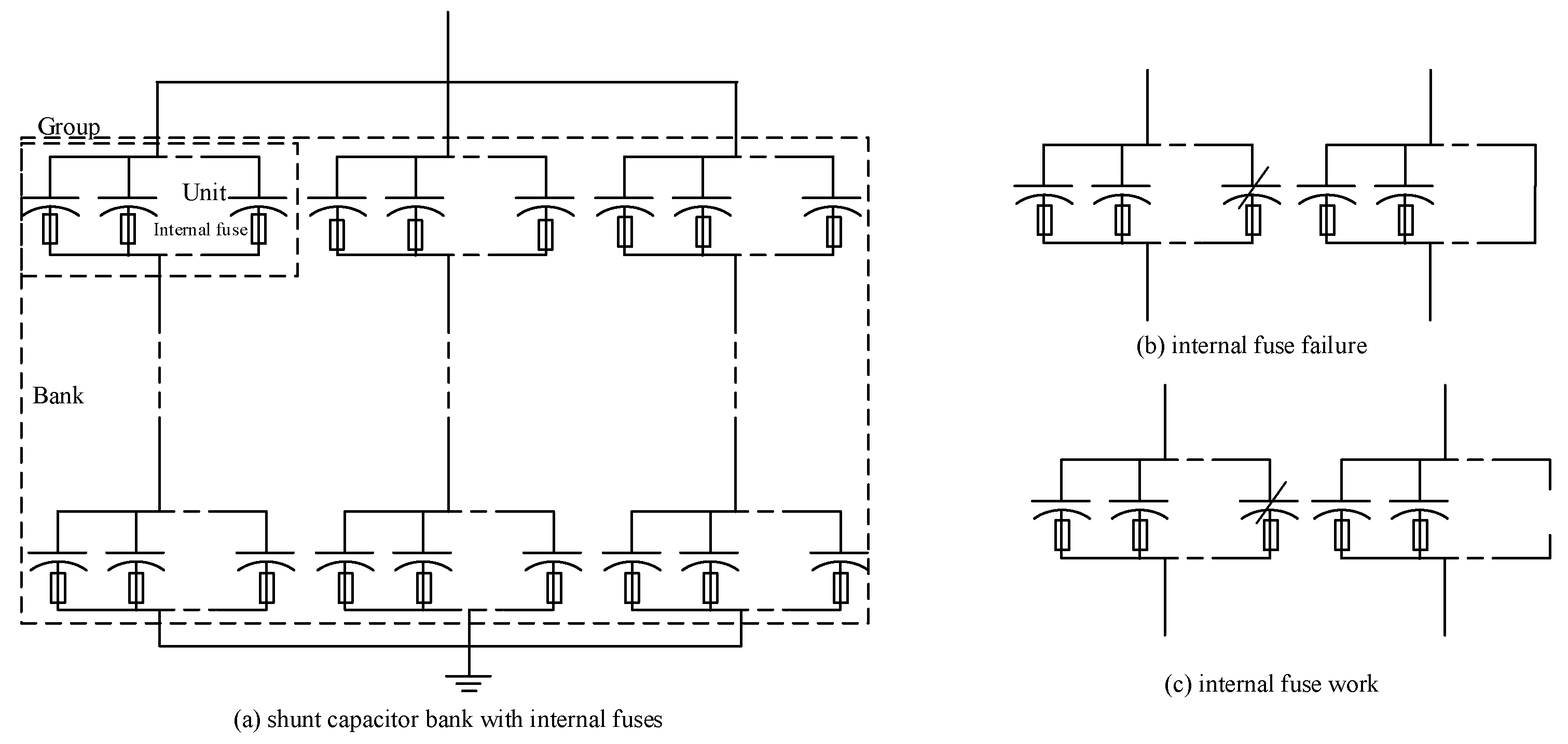
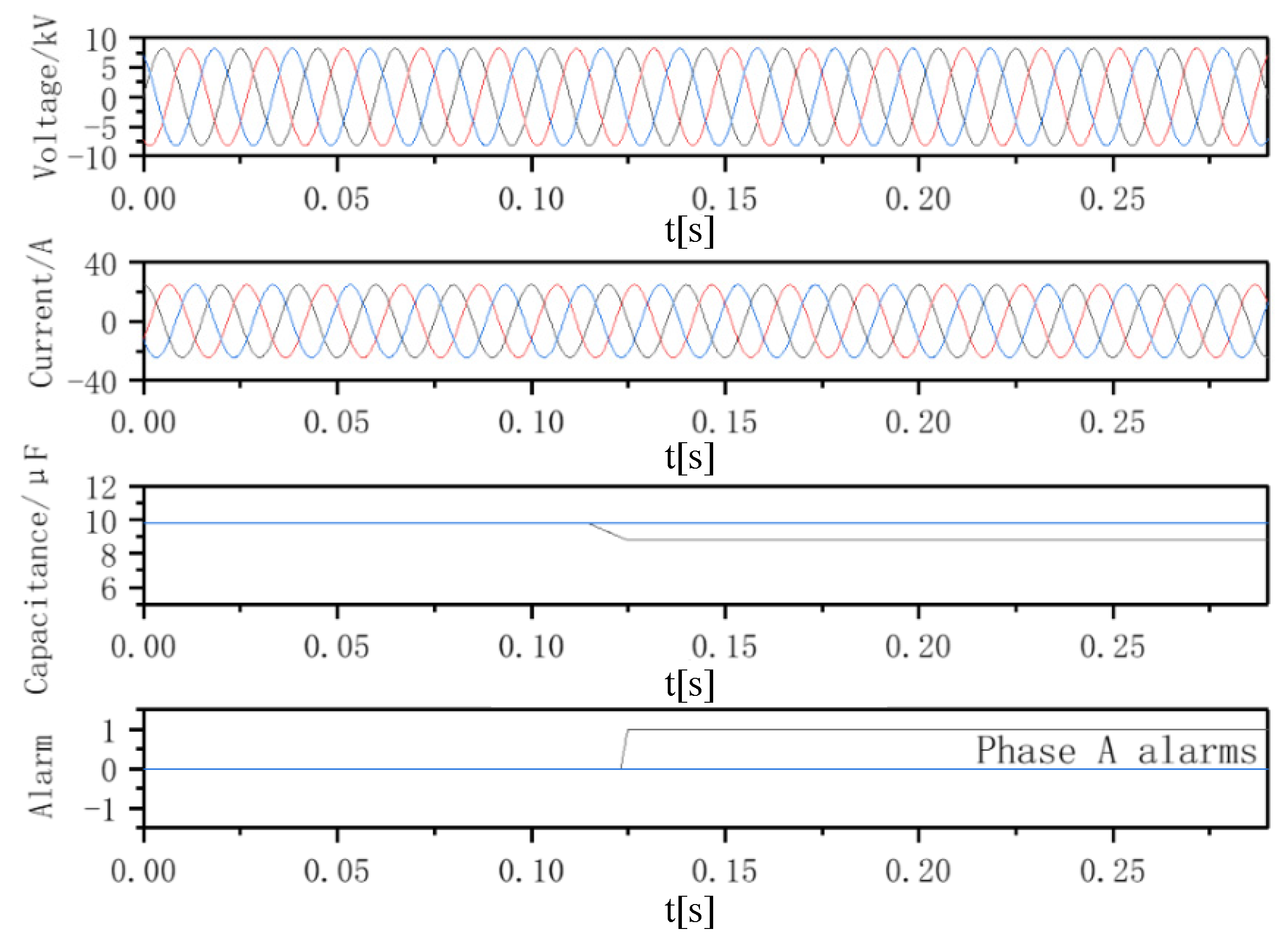
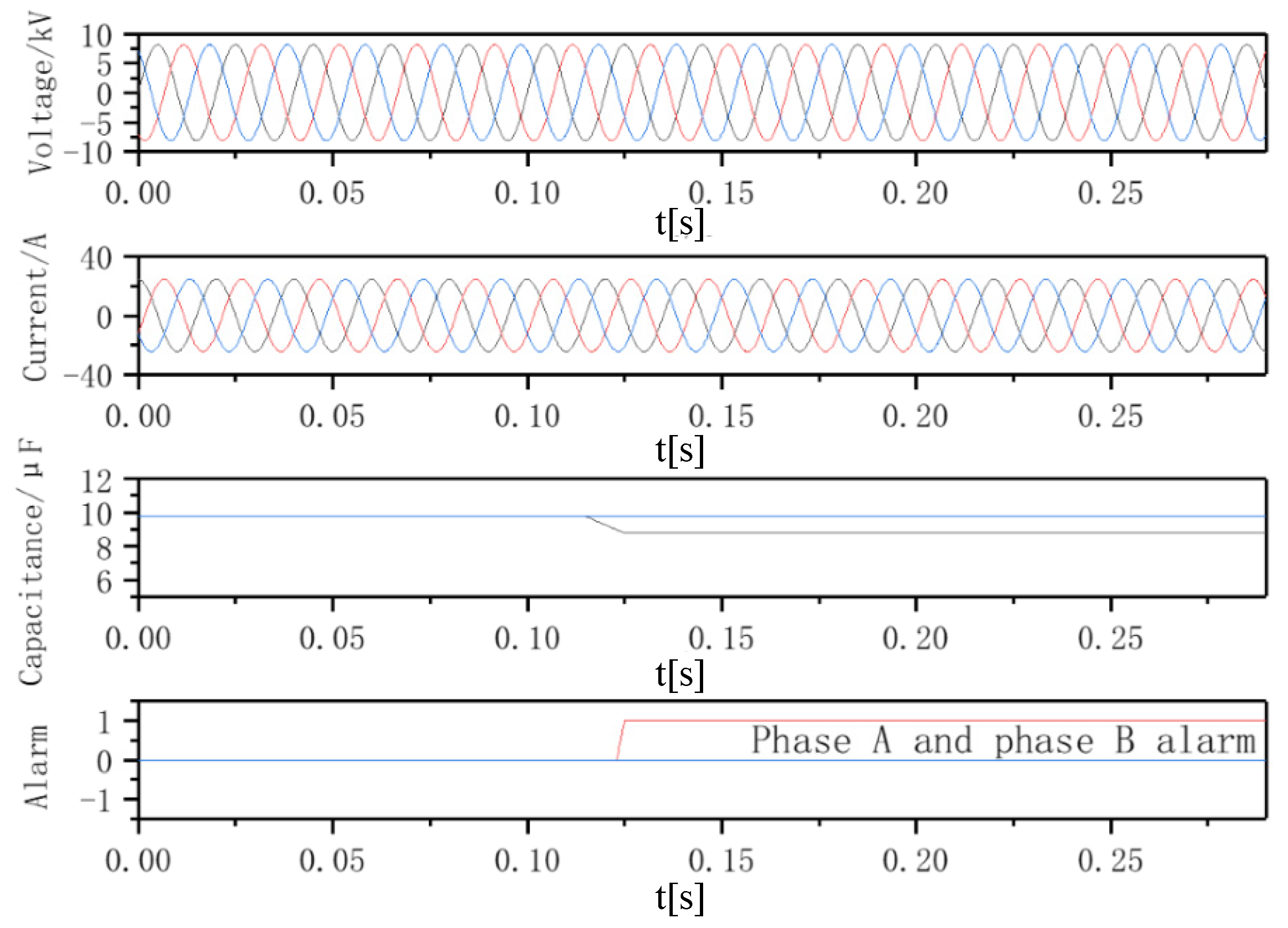
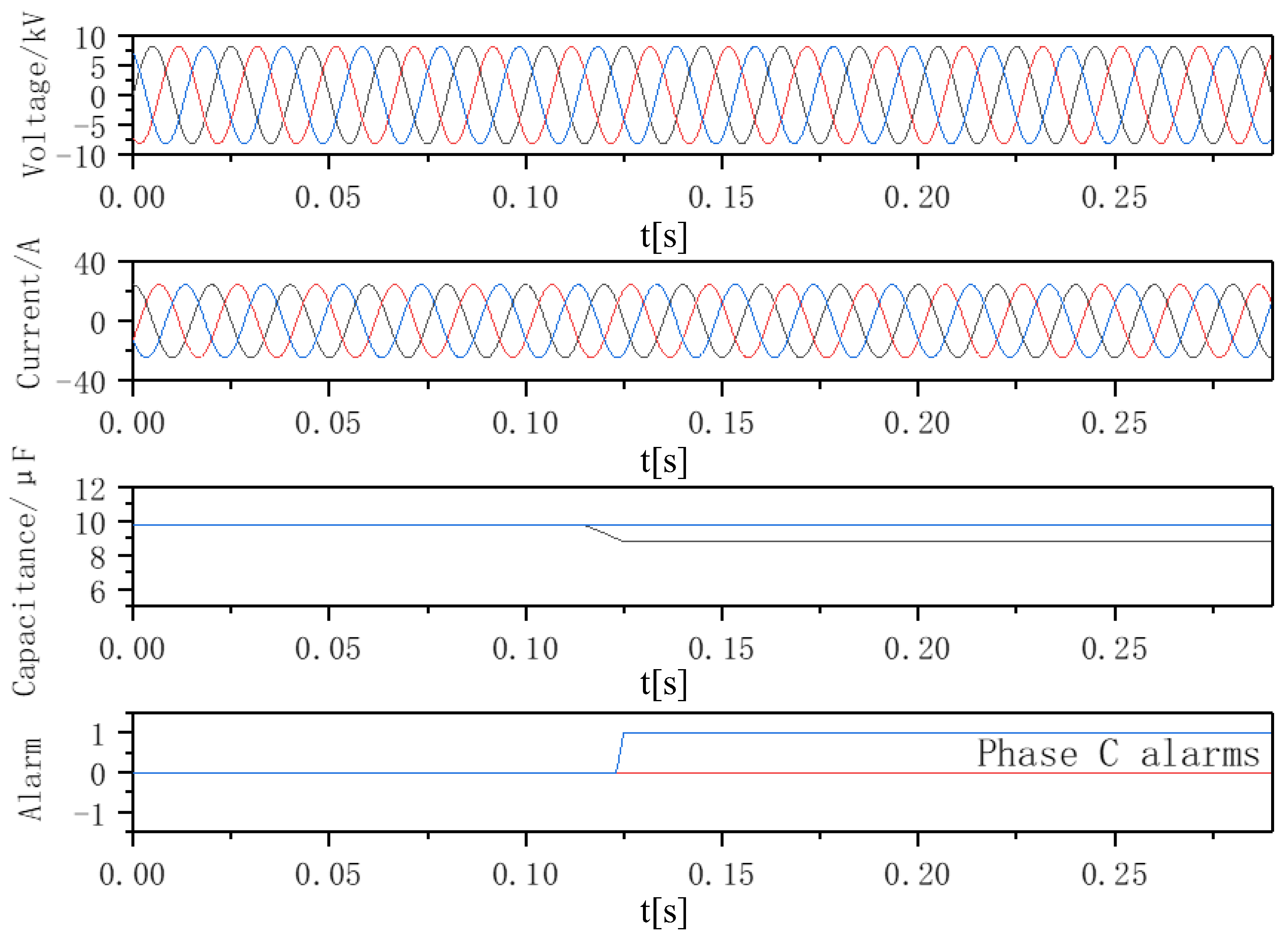
3.1. Capacitor Internal Fault
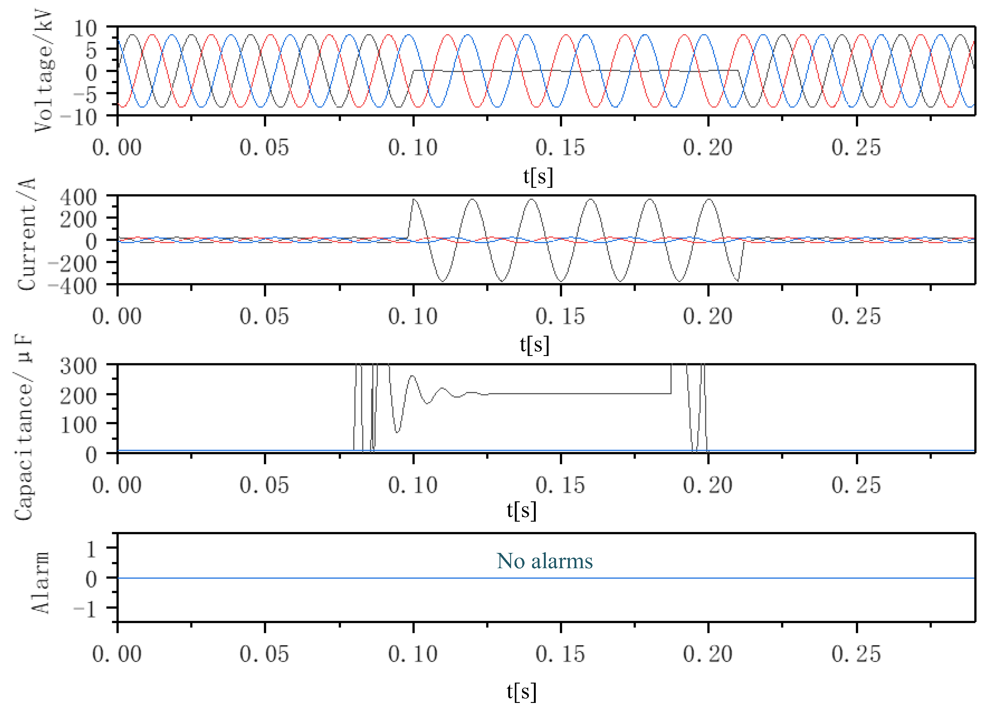
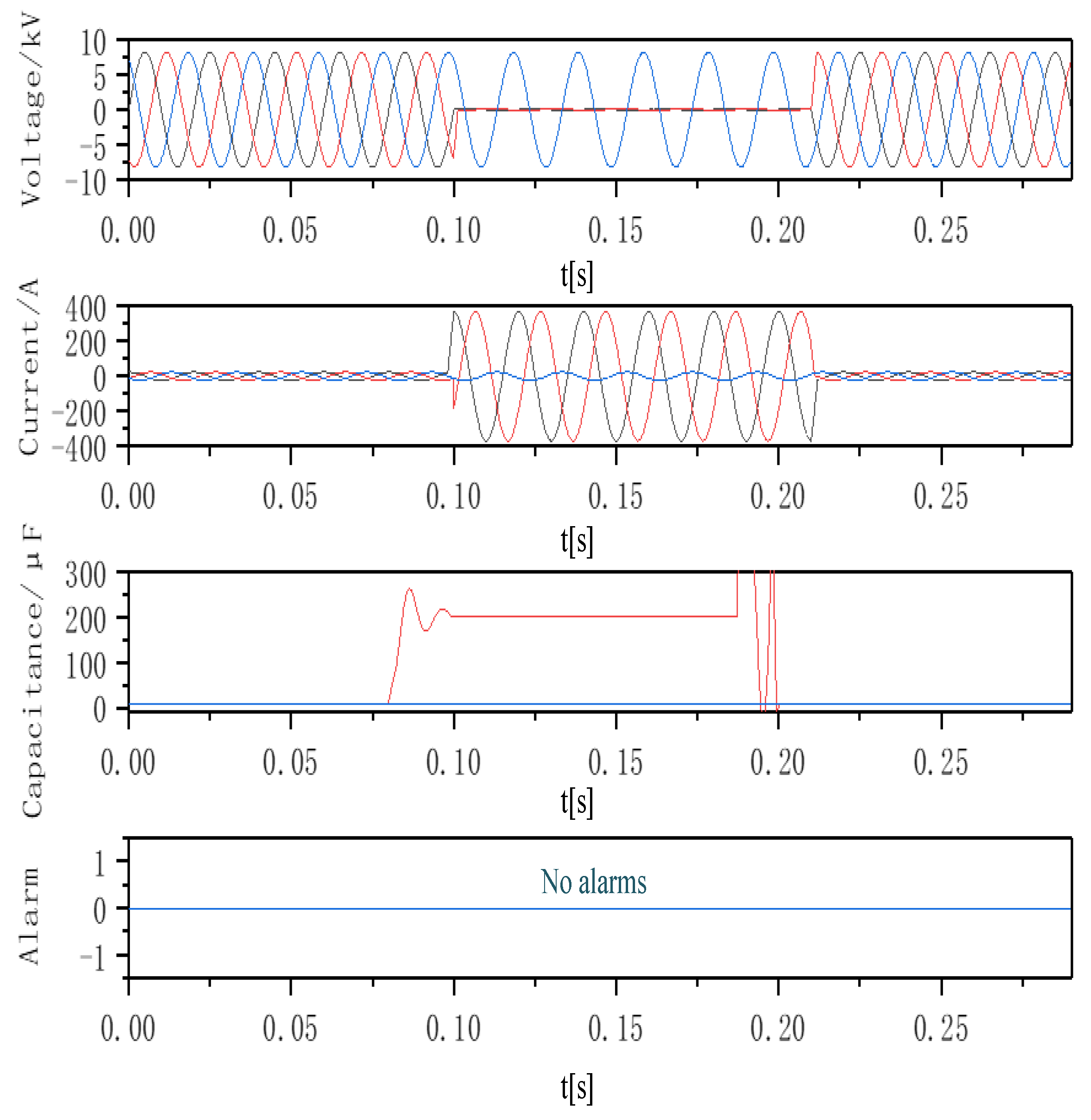
Figure 6 shows the calculation results when phase A capacitance declined by 10% of the standard value. The bus voltage remained unchanged. Phase A RMS current varied from 20.26 A to 18.96 A. Phase B/C RMS current varied from 20.26 A to 19.94 A. As can be seen from the figure, the capacitance changes slightly, the power system still operates normally and the voltage and current do not change significantly. It is correctly identified that the variability of phase A capacitance is out of specification and a phase A alarm is issued. The calculation result of the capacitance is 8.7919 μF; the actual capacitance is 8.784 μF (with less than 0.1% relative error).
Figure 7 shows the simulation when the phase A and B capacitances declined by 10% of the standard capacitance value. The bus voltage remained unchanged. Phase A/B RMS current varied from 20.26 A to 18.55 A. Phase B/C RMS current varied from 20.26 A to 19.54 A. As can be seen from the figure, this method can correctly detect that the capacitance changes of phase A and phase B are out of specification and issue an alarm. The calculated capacitance value for phase A/B is 8.7972 μF; the actual capacitance is 8.784 μF (with only 0.15% relative error).
Figure 8 shows the simulation when the capacitances of three phases change at the same time. (A, B and C declined 2%, 4% and 8%, respectively, compared with the standard value). The bus voltage remained unchanged. The phase A RMS current varied from 20.26 A to 19.57 A. The phase B RMS current varied from 20.26 A to 19.37 A. The phase C RMS current varied 20.26 A to 18.97 A. It can be seen from the figure that when there is a deviation in the initial parameters, capacitor monitoring can correctly detect that the phase C capacitance change exceeds specified values and a phase C alarm is triggered. The calculated result of the capacitances of phase A and B are 9.4608 μF (the actual capacitance values are 9.5648 μF and 9.3696 μF, the relative error is 1.09% and 0.97%). The calculated result of phase C capacitance is 8.9873 μF, the actual capacitance is 8.9792 μF and the relative error is 0.09%. There is a certain error in the calculated results of the normal phases A and B due to the initial deviation, but within the acceptable range, the capacitance value of the faulty phase C is still accurately calculated, the abnormality is correctly identified, and an alarm is issued.
The above results show that when some capacitor units are faulty, the slight change of capacitance value can be accurately detected. When the capacitance value changes beyond the shunt capacitor guidelines, or a statistical data comparison flags the value as abnormal, an alarm will be issued, which is convenient for maintenance.

3.2. External Fault

External faults occur when the fault accrues on a bus or line. The relay protections operate in these cases. The bus voltage almost drops to zero, and the capacitance value calculation is meaningless in this situation. In addition, capacitor monitoring should not trigger an alarm at external fault. Figure 9 shows the normal operation of the bus in the case of a single-phase ground fault. It can be seen from the figure that the capacitance value before and after the fault has a bump, because when calculating the current and voltage, a short circuit in one cycle causes a sudden change during the fault. The capacitance value is stable, and its calculated value is 208.23 μF, because when an external fault occurs, the measured impedance is the impedance from the measuring point to the short circuit point. The external fault should be tripped by the relay protection, and the capacitor monitoring should not trigger an alarm. Adding a low-voltage block make the alarm would not malfunction during the external fault.
Figure 10 shows the normal operation of the bus in the case of phase A and B grounding faults. During the fault, the calculated phase A and phase B capacitance values are both 208.23 μF; A, B two-phase low-voltage criteria are activated; two-phase capacitor failure monitoring is no longer active; and no malfunction occurred.
The above results show that the capacitor fault alarm does not malfunction, and the fault is removed by the protection mechanism.
Summarizing various faults of capacitors as shown in Appendix A, it can be seen that this method can correctly detect the internal faults and locate the abnormal phase. This is convenient for maintenance and repair work.

4. Conclusions

The on-line monitoring method for shunt capacitors proposed in this paper has the following characteristics:
(1) This monitoring method is applicable to shunt capacitor banks of all connection types. It can be realized only by using a relay protection device, with no additional device to measure the state quantity. The method is economical and convenient.
(2) In the event of a slight capacitor failure or abnormality, the abnormal phase can be detected to maintain safe operation.

Author Contributions

Conceptualization, Y.L. and Z.W.; methodology, Y.L.; software, Y.L.; validation, J.G.; formal analysis, Z.W.; investigation, J.G.; resources, J.G.; data curation, J.G.; writing—original draft preparation, Y.L.; writing—review and editing, Y.L.; visualization, J.G.; supervision, Z.W.; project administration, J.G.; funding acquisition, J.G. All authors have read and agreed to the published version of the manuscript.

Funding

This research received no external funding.

Data Availability Statement

The data presented in this study are openly available in IEEE, at references [13,24].

Conflicts of Interest

The authors declare no conflict of interest.

Appendix A

Table A1. Alarm results in each capacitor fault.
Fault ConditionsFault Phase ImpedanceAlarmResult Analysis
ABCABC
A-phase capacitor failureabnormalnormalnormalYesNoNoCapacitor failure, faulty phase correct alarm
Bphase C capacitor failurenormalabnormalabnormalNoYesYesCapacitor failure, faulty phase correct alarm
Three-phase capacitor failureabnormalabnormalabnormalYesYesYesCapacitor failure, faulty phase correct alarm
A-phase short circuitabnormalnormalnormalNoNoNoExternal fault does not alarm, the signal is correct
Bphase C short circuitnormalabnormalabnormalNoNoNoExternal fault does not alarm, the signal is correct
Three-phase short circuitabnormalabnormalabnormalNoNoNoExternal fault does not alarm, the signal is correct

References

  1. Kinjo, T.; Senjyu, T.; Urasaki, N.; Fujita, H. Output levelling of renewable energy by electric double-layer capacitor applied for energy storage system. IEEE Trans. Energy Convers. 2006, 21, 221–227. [Google Scholar] [CrossRef]
  2. Aziz, M.M.A.; Abou El-Zahab, E.E.D.; Ibrahim, A.M.; Zobaa, A.F. Effect of connecting shunt capacitor on nonlinear load terminals. IEEE Trans. Power Deliv. 2003, 18, 1450–1454. [Google Scholar] [CrossRef]
  3. Panda, N.R.; Pachpund, S. Capacitor Bank Balancing: Causes and Practical Levels of Unbalance. IEEE Ind. Appl. Mag. 2022, 28, 12–19. [Google Scholar] [CrossRef]
  4. Pour, M.R.; Azimian, M. Analysis of high voltage shunt capacitor bank over-voltage breakdown detection. Future Energy 2022, 1, 16–23. [Google Scholar] [CrossRef]
  5. Wei, J.; Lan, J.; Jiang, P. MRFO Based Optimal Filter Capacitors Configuration in Substations with Renewable Energy Integration. In Proceedings of the 2022 4th Asia Energy and Electrical Engineering Symposium, Chengdu, China, 25–28 March 2022; pp. 328–333. [Google Scholar]
  6. Sun, H.; Li, H.; Yang, S. Research on the Analysis of Unbalanced Current Alarm Factors and Solution Measures Based on Fixed Series Compensation Devices. In Proceedings of the 2022 4th International Conference on Power and Energy Technology (ICPET), Xining, China, 28–31 July 2022; pp. 369–374. [Google Scholar]
  7. Tian, Q.; Zhu, T. Shunt capacitor bank protection in UHV pilot project. In Proceedings of the 2016 China International Conference on Electricity Distribution (CICED), Xi’an, China, 10–13 August 2016; pp. 1–5. [Google Scholar]
  8. Mei, N.; Li, Y.; Duan, X. Study on high voltage capacitor unbalance protection in HVDC projects. In Proceedings of the 2009 Asia-Pacific Power and Energy Engineering Conference, Wuhan, China, 28–30 March 2009; pp. 1–4. [Google Scholar]
  9. Esponda, H.; Guillen, D.; Vazquez, E. Energy modes-based differential protection for Shunt capacitor banks. In Proceedings of the 15th International Conference on Developments in Power System Protection, Liverpool, UK, 9–12 March 2020; pp. 1–6. [Google Scholar]
  10. Jouybari-Moghaddam, H.; Sidhu, T.; Parikh, P. Enhanced fault location method for shunt capacitor banks. In Proceedings of the 2017 70th Annual Conference for Protective Relay Engineers, College Station, TX, USA, 3–6 April 2017; pp. 1–11. [Google Scholar]
  11. Lertwanitrot, P.; Ngaopitakkul, A. Application of Magnitude and Phase Angle to Boundary Area-Based Algorithm for Unbalance Relay Protection Scheme in 115-kV Capacitor Bank. IEEE Access 2021, 9, 35709–35717. [Google Scholar] [CrossRef]
  12. Jouybari-Moghaddam, H.; Sidhu, T.S. A study of capacitor element failures in high voltage Shunt Capacitor Banks. In Proceedings of the 2017 IEEE 30th Canadian Conference on Electrical and Computer Engineering, Windsor, ON, Canada, 30 April–3 May 2017; pp. 1–4. [Google Scholar]
  13. Zhang, M.; Du, J.; Gao, B. Research on the implementation scheme of shunt capacitor protection and monitoring. In Proceedings of the 2017 China International Electrical and Energy Conference, Beijing, China, 25–27 October 2017; pp. 356–359. [Google Scholar]
  14. Pavan, P.S.; Das, S. Novel method for location of internal faults in ungrounded double wye shunt capacitor banks. IEEE Trans. Power Deliv. 2020, 36, 899–908. [Google Scholar] [CrossRef]
  15. Shilong, L.; Yufei, T.; Mingzhong, L. An Novel On-line Monitoring Method for Double-Y Type Shunt Capacitor Bank. In Proceedings of the 2020 Asia Energy and Electrical Engineering Symposium, Chengdu, China, 28–31 May 2020; pp. 296–300. [Google Scholar]
  16. Xiaoyu, C.; Jianyong, Z.; Jun, M. Power capacitor banks failure warning method based online intelligence LC oscillation frequency variation and its implementation. Power Syst. Prot. Control. 2015, 43, 144–149. [Google Scholar]
  17. Jianjun, Z.; Honghua, S. Research of On-line Monitoring System for High Voltage Shunt Capacitors. Power Capacit. React. Power Compens. 2013, 34, 22–27. [Google Scholar]
  18. Goodarzi, A.; Allahbakhshi, M. Online condition monitoring algorithm for element failure detection and fault location in double wye shunt capacitor banks. Int. J. Electr. Power Energy Syst. 2022, 137, 107864. [Google Scholar] [CrossRef]
  19. Chi, D.; Tang, H.; Chang, H. Failure analysis of fuse for external protection of capacitor bank. In Proceedings of the 18th International Conference on AC and DC Power Transmission (ACDC 2022), Windsor, ON, Canada, 2–3 July 2022; pp. 185–188. [Google Scholar]
  20. Jena, S.; Mohanty, R.; Pradhan, A.K. A traveling wave based method for protection of shunt capacitor bank. IEEE Transactions on Power Delivery. IEEE Trans. Power Deliv. 2021, 37, 2599–2609. [Google Scholar] [CrossRef]
  21. Mohanty, R.; Pradhan, A.K. Fast and Sensitive Time-Domain Protection of Shunt Capacitor Banks. In Proceedings of the 2021 9th IEEE International Conference on Power Systems (ICPS), Kharagpur, India, 16–18 December 2021; pp. 1–6. [Google Scholar]
  22. Bastos, A.F.; Santoso, S. Condition monitoring of circuit switchers for shunt capacitor banks through power quality data. IEEE Trans. Power Deliv. 2019, 34, 1499–1507. [Google Scholar] [CrossRef]
  23. Horton, R.; Warren, T.; Fender, K. Unbalance protection of fuseless, split-wye, grounded, shunt capacitor banks. IEEE Trans. Power Deliv. 2002, 17, 698–701. [Google Scholar] [CrossRef]
  24. IEEE Guide for the Protection of Shunt Capacitor Banks—Redline (C37.99-2012—Redline). IEEE Std. 2013, 1–299.
Figure 1. Shunt capacitor bank with internal fuses.
Energies 16 01615 g001
Figure 2. Most common capacitor bank configurations.
Energies 16 01615 g002
Figure 3. Capacitor equivalent circuit.
Energies 16 01615 g003
Figure 4. Monitoring logic.
Energies 16 01615 g004
Figure 5. Shunt capacitor bank at 10 kV bus.
Energies 16 01615 g005
Figure 6. Phase A internal fault.
Energies 16 01615 g006
Figure 7. Phase A and B internal fault.
Energies 16 01615 g007
Figure 8. Phase C internal fault.
Energies 16 01615 g008
Figure 9. Phase A ground fault simulation results.
Energies 16 01615 g009
Figure 10. A and B grounded external fault.
Energies 16 01615 g010
Disclaimer/Publisher’s Note: The statements, opinions and data contained in all publications are solely those of the individual author(s) and contributor(s) and not of MDPI and/or the editor(s). MDPI and/or the editor(s) disclaim responsibility for any injury to people or property resulting from any ideas, methods, instructions or products referred to in the content.

