Article

Premixed Propane–Air Flame Propagation in a Narrow Channel with Obstacles

1
Department of Physics, Novosibirsk State University, 630058 Novosibirsk, Russia
2
Ishlinsky Institute for Problems in Mechanics RAS, 119526 Moscow, Russia
3
Department of Experimental Physics, Surgut State University, 628412 Surgut, Russia
*
Author to whom correspondence should be addressed.
Energies 2023, 16(3), 1516; https://doi.org/10.3390/en16031516
Submission received: 29 December 2022 / Revised: 27 January 2023 / Accepted: 30 January 2023 / Published: 3 February 2023
(This article belongs to the Section J1: Heat and Mass Transfer)

Abstract

:
Flame interaction with obstacles can affect significantly its behavior due to flame front wrinkling, changes in the flame front surface area, and momentum and heat losses. Experimental and theoretical studies in this area are primarily connected with flame acceleration and deflagration to detonation transition. This work is devoted to studying laminar flames propagating in narrow gaps between closely spaced parallel plates (Hele–Shaw cell) in the presence of internal obstacles separating the rectangular channel in two parts (closed and open to the atmosphere) connected by a small hole. The focus of the research is on the penetration of flames through the hole to the adjacent channel part. Experiments are performed for fuel-rich propane–air mixtures; combustion is initiated by spark ignition near the far end of the closed volume. Additionally, numerical simulations are carried out to demonstrate the details of flame behavior prior to and after penetration into the adjacent space. The results obtained may be applicable to various microcombustors; they are also relevant to fire and explosion safety where flame propagation through leakages may promote fast fire spread.

1. Introduction

Flame propagation in complex geometries has attracted the attention of many researchers. Obstacles of various kinds cause momentum and heat losses, and generate significant perturbations to the flow field, flame front stretching, deformation, or wrinkling that increase the flame-front surface area [1]. These interactions are augmented by intrinsic flame instabilities of different types (Darrieus–Landau, diffusive–thermal, etc.) [1,2,3]. Even in straight smooth tubes, the flame front may assume the known “tulip” shape [4], or flame propagation may become impossible if the tube diameters are smaller than some critical value.
During the past years, much attention was given to flame acceleration due to the presence of obstacles. This phenomenon is of paramount importance for gas explosions in congested environments, as well as in application to flammable gas cloud explosions [5]. The basic mechanism for flame acceleration is the flow turbulization in front of the flame, increasing significantly the flame surface area and overall combustion rate. Once the flame speed becomes close to the speed of sound, deflagration to detonation transition (known as DDT) may occur, posing much greater danger due to supersonic propagation speed and the overpressure levels rising from hundreds millibar to as high as 15 bar [6].
Numerous studies on flame acceleration and DDT have been performed during the past few decades. In order to have controlled conditions and fair instrumentation, most of the studies were performed in rectangular channels or pipes obstructed internally by arrays of obstacles with predefined blockage ratio and spacing distance. Some of the recent experimental and theoretical works in this field are [7,8,9,10,11,12,13,14]. The application areas of DDT research range from the pulsed detonation engines [7] to gas explosion accidents in process industries, such as the chemical industry, coal mines, and oil depots [13,14]. The test sections of the experimental facilities used for DDT studies are typically composed of a long square channel: 76.2 mm × 76.2 mm cross section, 1.68 m long in [7]; 76 mm × 76 mm cross section and 2.44 m long in [8]; 60 mm × 60 mm × 1000 mm in [12]; and 100 mm × 100 mm × 1000 mm in [13,14]. Obstacles are fixed either on one side wall of the channel [7,14] or on two opposing walls [8,10]. An array of obstacles with a fixed separation distance is typically used in the experiments [7,8,9,13,14], although the effect of a single obstacle was studied in [10]. The instrumentation used in the experiments allowed the pressure profiles, shock wave structures, and the flame front velocity to be determined; the Schlieren visualization technique was applied in [7,8]. Increasingly, experiments were accompanied by numerical simulations of the flow field and combustion zone propagating in the obstructed channel [9,10,12,13,14] in the two-dimensional and three-dimensional formulation.
An important characteristic of the congested channel is the blockage ratio, defined as 1 h / H , where h is the size of the opening above the obstacles and H is the total channel height. The above-mentioned experiments and simulations were performed for a fixed blockage ratio varying in the range 0.33, 0.5, and 0.67 [8] or fixed at 0.5 [10] or 0.42 [7]. The critical role of blockage ratio for flame acceleration in channels with tightly spaced obstacles was emphasized in a theoretical analysis [11]. Recently, studies on the effects of varying blockage ratio and mixed obstacles were reported [12,13,14].
Another research avenue related to flame propagation in channels where interactions with solid boundaries play an important role is the premixed flame propagation in channels with one dimension much smaller than the other two (the Hele–Shaw cell). In such channels, flame instabilities of different types develop, leading to flame wrinkling, mainly in the two directions along which the channel has a large size. As a result, transformation of a planar or cylindrical flame front into a cellular flame front occurs, with the cells, being dynamic structures, appearing on the flame front and merging dynamically. Quasi-two-dimensional geometry of the Hele–Shaw cell provides an opportunity to record the cellular flame propagation and visualize the cell evolution history in more detail than in the full three-dimensional configurations.
The theory of cellular flame propagation in a quasi-2D channel was developed in [15], where the effects of heat and momentum losses on the flame instability and speed were analyzed. Since then, experimental studies on premixed flames in Hele–Shaw cells were performed in [16,17,18,19,20,21,22].
In [16], the effect of Lewis number was studied by using hydrogen–oxygen–inert mixtures in a range of equivalence ratios; the combustion chamber was 59.5 cm long, 39.5 cm wide, and 0.5 inches (1.27 cm) thick. It was shown that the Darrieus–Landau and diffusive–thermal instability types play the predominant role in the development of cellular flame structure. In [17,18,19], a vertical Hele–Shaw cell of 1500 × 500 × 5 mm dimension was used to study the instability of a linear flame. The flame was generated first as a steady-state front in an upward mixture flow, and then it was allowed to propagate downward through a quiescent fuel–air mixture after the flow was stopped. The development of perturbations on the flame front was recorded, the perturbation growth rate was determined and compared with the linear analysis; numerical simulations were also applied to study the nonlinear behavior of the flame.
A horizontal Hele–Shaw cell formed by two glass disks was used in [20,21] to study the propagation of cylindrical flames initiated by spark ignition. A unique visualization technique based on the long-exposure photo shots in a dark room was used to record not only the instantaneous flame front shape, but also the trajectories of the angular points (cusps) separating the adjacent cells. It was shown that the average horizontal cell size developing in nearly stoichiometric propane–air mixture flames is approximately 10 times larger than the width of the gap between the plates. Similar studies of methane–air flame propagation in narrow gaps were reported in [22] with emphasis on the effects of equivalence ratio and gap width.
In addition to studying the general flame dynamics and instability development, the Hele–Shaw cell experiments were also performed to analyze the oscillatory flame behavior [23], or coupling of vibroacoustic waves with premixed flames [24]. Worth noting are numerical simulations of cellular flames in narrow gaps performed on the basis of a quasi-2D model [25], lattice Boltzmann method [19], or three-dimensional model with detailed chemistry [26].
Of definite interest from the fire and explosion safety point of view are the processes of flame propagation or quenching in narrow gaps, and flame penetration through holes in fire barriers. For example, in [27], combustion of ultralean hydrogen–air mixtures in the narrow space between parallel plates was studied, both experimentally, and numerically. It was shown that, contrary to expected flame quenching, propagation of several compact flame kernels was observed. These flame cells traveled to the whole length of the installation, either along linear paths or forming multiple dendrite-like paths. This finding is important as it highlights the hazards of even minor cracks in walls through which hydrogen flames can propagate. In [28], experiments and numerical simulations were performed in a rectangular tube equipped with flat channels to study the quenching of methane–air deflagrations, in application to production or design of industrial flame arresters. In [29], a series of experiments was carried out to investigate deflagration flame propagation and extinguishment in vessels connected by parallel narrow channels. The results showed that flame propagation was effectively inhibited by parallel narrow channels with gaps smaller than 3 mm; dependence of extinguishing distance and average velocity of deflagration flame propagation in parallel narrow channels on the gap width was obtained. Hydrogen flame penetration through a hole in a barrier was studied experimentally in [30], where a cylindrical confined combustion chamber equipped with a single-hole perforated plate was used; the results obtained are applicable to flame development in pipelines with various obstacles.
Flame propagation in narrow channels with obstacles and internal passages is also of interest in application to various microengines, microcombustors, thrusters, and other small-scale devices [31]. For example, in [32], flame propagation experiments were performed in geometries relevant to next-generation electrochemical energy systems with high surface-to-volume ratios, such as fuel cells or flow batteries. These systems typically have rectangular cross-sections with the potential for regular obstructions consisting of electrodes or support structures.
One of the distinct features of flame propagation through small holes in barriers located in closed or semi-closed channels is that the process of pressure equalization between the channel sections is hindered by the small cross-section area of the hole. As a result, significant pressure drop can develop across the barrier, resulting in gas acceleration in the hole to high velocities and formation of a gas jet in the lower-pressure channel section. Therefore, it is necessary to study the details of flame propagation through small holes in the barriers separating closed and open channel parts, reveal the temperature and velocity fields developing near the perforated barrier, evaluate the mixing effects in the lower-pressure section, etc.; these reasons were the principal motivation for the current research.
The objectives of this study are:
  • To apply the visualization possibilities provided by the Hele–Shaw cell setup to the study of flame propagation in a narrow gap between two closely spaced parallel plates in the presence of internal obstacles dividing the rectangular channel in two chambers (closed or open to the atmosphere), connected by a small hole;
  • To reveal the features of flame penetration through the hole to the adjacent chamber in various channel configurations, with the ignition point position near the open or closed end;
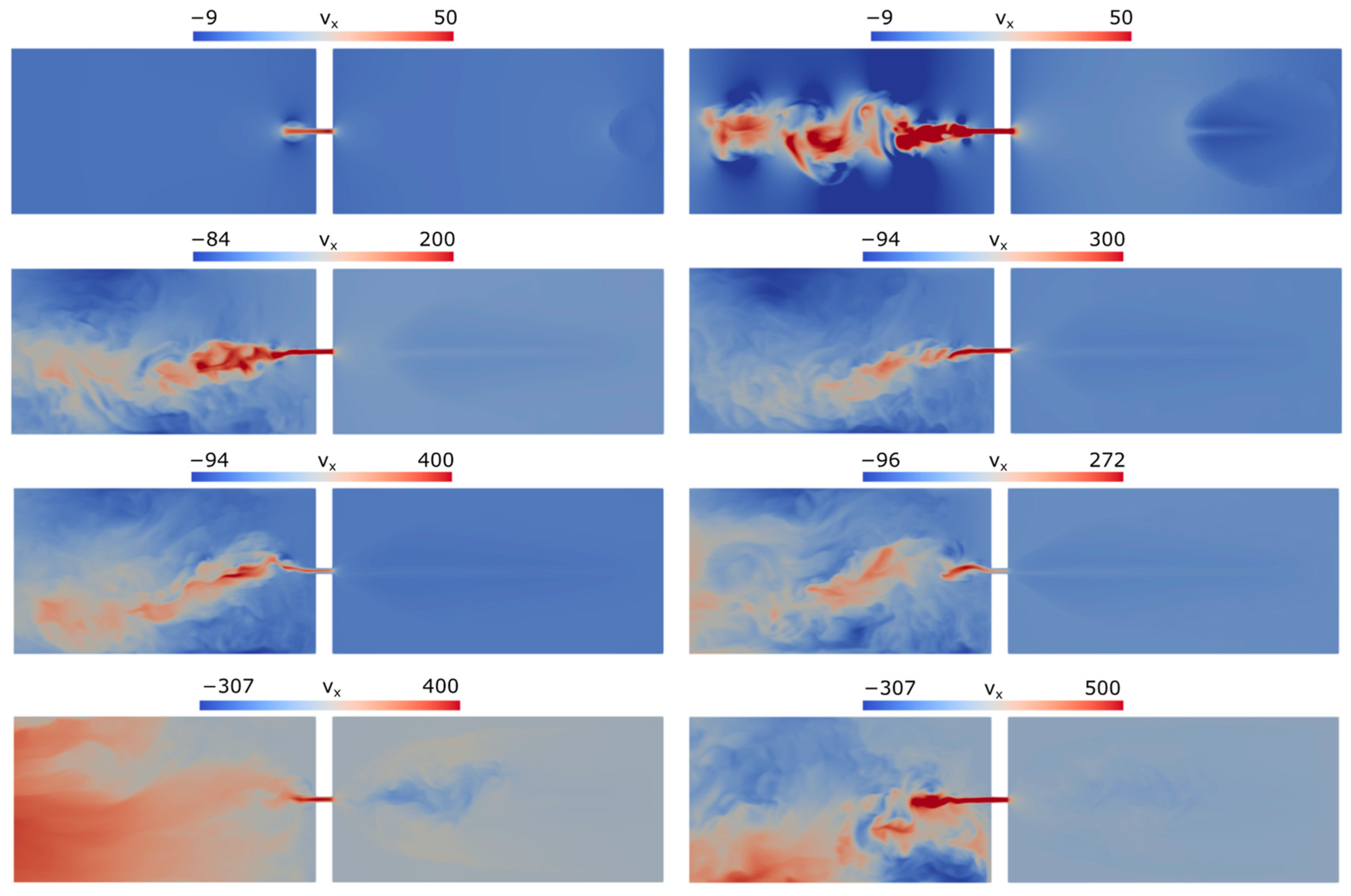
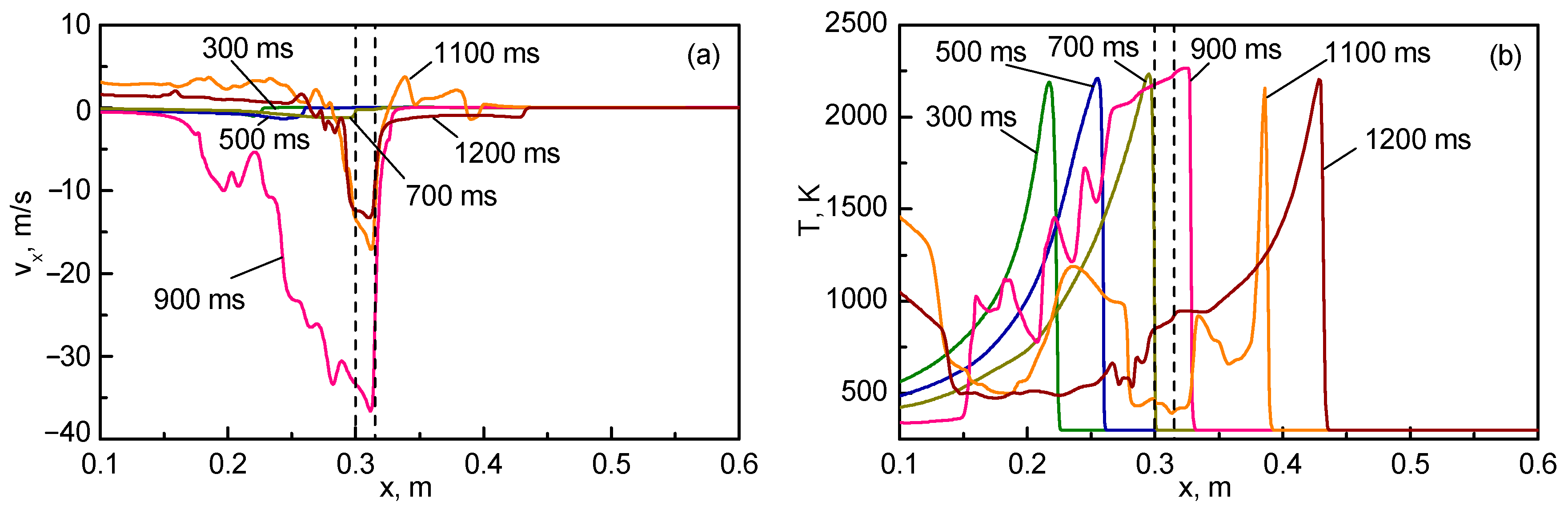
  • To obtain through numerical simulations the flow details that are not measured or recorded experimentally, including the velocity field in the hole and adjacent volumes.
The novelty of this work in comparison with the abovementioned studies on flame acceleration and DDT in channels with obstacles [7,8,9,10,11,12,13,14] is that we consider the case of very large blockage ratio (up to 97%), and only a single obstacle is present. The barrier width (or flame passage distance between the chambers) is shorter than in the experiments [29,32] but longer than in [30] (15 mm vs. 3 mm). Thus, the current work extends the available research both in terms of the channel geometry (quasi-two-dimensional setup), operating conditions, and ignition conditions (near the open or closed channel end).

2. Experimental Facility

Experiments were performed in horizontal rectangular channels formed by two transparent acrylic glass (PMMA) plates. In Figure 1, the experimental setup is presented.
The channel length was 1.38 m, width 0.15 m, the gap between the acrylic plates (1) was variable in the range 3–9 mm. The side walls (2) of the channel were formed by plates made from opaque black acrylic material. The right side of the channel was always closed, the left side could be open or closed depending on the experiment.
The obstacle (3) was an additional wall made of the same acrylic material as the channel walls with an open gap, installed in the middle of the channel, perpendicular to the longest side of the channel. The height of the obstacle was equal to the distance between the bottom and top plates of the channel, so that the only way for the flame front (4) and gas flow was the gap in the middle of the obstacle. The gap was in the center of the obstacle wall. The obstacle width was 2 cm; the transverse gap size was 5 mm.
The channel was filled with the propane–air mixture through an inlet nozzle (5) passing through the center of the wall covering the right side of the channel. Experiments were carried out with fuel-rich mixtures prepared in the displacement gasometer (12). The displacement gas meter consisted of two 20 L tanks connected to each other with a hose, allowing preparation of 15 L of combustible mixture with the relative accuracy of 2%. Gas mixture from the gas meter was supplied to the channel through a hose (7) attached to the nozzle and equipped with a porous flame extinguisher (9). The volume of supplied gas was measured by the gas volume meter (11) and was at least 3 times the internal volume of the channel. When filling with a gas mixture, the left end of the channel was nonhermetically closed to reduce the intensity of dilution of the gas mixture entering the chamber with ambient air. After filling the channel with a fuel–air mixture, the gas supply was blocked by a globe valve (10).
In the experiments with an open channel, opening of the left side was performed after a delay of about 30 s after filling the internal space of the channel with fuel–air mixture, in order to let the mixture become quiescent after the filling process. Mixture ignition was performed immediately after opening the left side, or after the delay time, by a high-voltage spark between electrodes (5) powered by an ignition coil (8). The electrodes were installed in the center of the right wall of the channel. The distance between the electrodes was 1.5 mm.
Flame propagation was recorded either by a high-speed AOS X-PRI camera or by a Sony DSLR-A580 digital camera (13), installed above the channel obstacle. The Sony DSLR-A580 digital camera allowed us to record video at 25 frames per second with 1080 p resolution, while the X-PRI high-speed camera allowed for recording video with a higher frame rate, up to 1000 fps, but with relatively low resolution, 800 × 600 pixels. Owing to its limited resolution, the high-speed camera was zoomed to the channel obstacle in order to obtain a more detailed picture of the flame front passing through it, without a view of the ignition point and the end of the channel.

3. Numerical Modeling

3.1. Problem Formulation

The reacting multicomponent gas flow is described by the system of transient Navier–Stokes equations that includes the species continuity, gas momentum, and energy equations (see, e.g., [33]):
ρ y i t + ρ U + V i y i = W ˙ i ,       i = 1 N s p ,
ρ U t + ρ U U = p + τ ,
ρ h t + ρ U h = d p d t + q T .
Here, ρ is the density, p is the pressure, T is the temperature, U is the gas velocity, y i are the mass fractions of gas species, N s p is the number of species, V i is the diffusion velocity of i -th species, τ = η U + U T 2 3 I U is the viscous stress tensor, η and λ are the gas viscosity and thermal conductivity, h is the gas enthalpy (including the species heat of formation), q T is the heat flux, and W ˙ i is the i -th species mass reaction rate. The system of governing equations is closed by the ideal gas equation of state:
p = ρ R 0 T i = 1 N s p y i μ i ,  
where R 0 = 8.314 J/mol-K is the universal gas constant, and μ i is the molar mass of i -th species. The gas enthalpy is defined by
h = i = 1 N s p y i h i T ,
where the enthalpies of individual species are
h i T = Δ h f , i 298 + 298 T c p , i T d T .
Here, Δ h f , i 298 is the standard heat of formation and c p , i is the heat capacity of i -th species. The dependencies (5) and (6) are approximated by polynomials.
The diffusion velocities V i in (1) are given by a quasi-Fickian expression:
V i = y i 1 D i y i ,
where D i is the diffusion coefficient of i -th species into the rest of the mixture. Such an approximation is common in combustion studies; it gives acceptable accuracy at lower computational cost than the more rigorous Stefan–Maxwell model. The heat flux in the energy Equation (3) is given by
q T = λ T + ρ i = 1 N s p y i h i V i .
Transport coefficients η i and λ i for the species and the binary diffusion coefficients D i j are found from the kinetic theory of gases; the respective gas mixture properties η and λ are found by the empirical mixing rules (e.g., [34]). The mixture-average diffusion coefficients are found as D i = 1 y i / j i x j / D i j . Note that in this formulation the sum of all diffusive fluxes i = 1 N s p y i V i = v c 0 , and, in order to maintain mass conservation, the velocity v c is subtracted from the gas velocity U in the transport Equations (1) and (3) [33,34]. This correction is not necessary if the diffusion velocities are obtained from the Stefan–Maxwell equations.
The reaction rate for each species W ˙ i depends on the kinetic scheme; generally, it is the difference between the forward and backward reaction rates. Combustion of propane in air is a complex chemical process, and many detailed, reduced, skeletal, and global combustion schemes involving hundreds of reactions were proposed over the past few decades (e.g., see recent review [35]). For the purpose of the current study, focused more on the fluid-dynamic aspects of flame propagation rather than on such chemical kinetics-dependent phenomena as mixture ignition, extinction, flammability limits, etc., a one-step irreversible reaction mechanism was used because of its simplicity and low computational costs. The one-step global reaction of propane combustion is
C 3 H 8 + 5 O 2 3 CO 2 + 4 H 2 O ,
with the reaction rate defined by
k = A exp E R T C 3 H 8 n [ O 2 ] m .
Here, A is the pre-exponential factor, E is the activation energy, R = 8.314 J/mol-K is the universal gas constant, and n and m are the reaction orders with respect to fuel and oxidizer. These values are generally defined empirically, and many sets of constants have been proposed in the literature [36,37]. In this work, we applied the constants given in [37]: A = 3.291653 × 10 10 , E = 31,125.8 cal/mol, n = 0.856 , and m = 0.503 .
On the solid boundaries, the no-slip boundary conditions were posed for gas velocity; the wall temperature was assumed equal to the ambient value because the flame–wall interaction time is quite short to cause any noticeable heating of solid material. The diffusive fluxes of all species on the walls were assumed zero (chemically inert material).
The initial conditions corresponded to nonmoving gas at the ambient temperature and with a given fuel–air proportion (equivalence ratio). These conditions were set throughout the whole computational domain, except the ignition source was modeled by a cylindrical volume of hot, completely reacted gas. The position and size of the ignition kernel depended on the case being considered; they are given in the respective sections below.

3.2. Numerical Implementation

Numerical simulations supporting the experiments were carried out by a numerical model developed in the framework of OpenFOAM software [38]. The solver was based on the reactingFoam solver from the standard distribution; however, significant modifications were implemented to overcome the limitation connected with the calculation of the diffusion fluxes. Namely, it is assumed in the standard solver that all species have equal diffusion coefficients evaluated from the mixture temperature conductivity.
The coupled solver used for the solution of governing Equations (1)–(9) is based on the reactingFoam solver from OpenFOAM [38] that was used extensively by the combustion community for simulations of various combustion regimes. The reactingFoam solver was shown to perform quite well with predictions of turbulent combustion, including RANS and LES simulations; however, its use for prediction of laminar combustion is less successful because of simplified treatment of transport coefficients. A very promising approach, also followed in the present work, is to couple the reactingFoam solver with the libraries from the Cantera open-source chemical kinetics software [39]. An example of this coupled solver is given in [40], where extensive validation is performed for laminar and turbulent flows.
In the current work, a solver similar to [40] was developed independently. An appropriate program interface was developed, allowing the interactions between different software packages. As a result, solution of the stiff kinetics equations and calculation of thermodynamic and transport properties of individual species and gas mixture were performed by using the Cantera package [39], whereas the solution of the flow field, species, and energy conservation equations was carried out by the OpenFOAM solver.
Validation of the coupled software developed was performed by solving different laminar combustion problems, including the laminar premixed and diffusion flames with detailed kinetics [41]. Comparisons of simulations with experimental data on laminar flames of methyl methacrylate in air were carried out; good agreement was demonstrated for species concentration and temperature profiles in a buoyant flame at various heights above the fuel source.
Despite the quasi-two-dimensional geometry of the Hele–Shaw cell, numerical simulations were carried out in this work in the three-dimensional framework. However, to reduce the computational effort, only the upper half of the channel (with respect to its width, or along the z-coordinate, 0 z H / 2 ) was modeled; the symmetry boundary conditions were applied on the bottom boundary z = 0 .
Since the primary focus in this work was on the flame passage through the hole in the obstacle, rather than on the flame propagation in the channel as such, the channel part that the flame passes approaching the obstacle was taken shorter than in the experiments; its length was 30 cm. On the contrary, the channel part into which the flame propagated through the hole was 70 cm long, corresponding closely to the length of the experimental section (see Figure 1). More details on the initial conditions are given below when considering the numerical results obtained for the open- or closed-end configurations.
All simulations were carried out on Cartesian grids refined near the hole in the obstacle; in that area the cell sizes were square in the x y directions, with the cell size of 0.5 mm; in the z -direction (across the channel half-width) the mesh was uniform with the cell size of 0.45 mm (for 9 mm total gap width). The total number of cells used in most simulations was 2,171,400, while some simulations were carried out on a finer mesh (about 5 million cells). The computational domain geometry and a fragment of computational mesh near the hole in the obstacle are shown in Figure 2.

4. Results

4.1. Flame Propagation from Closed to Open Channel End

This flame propagation mode is featured by different conditions developing in the closed and open channel parts. Since the closed-part walls are impermeable, except for a small hole allowing only limited gas outflow, the hot products created by the flame cannot expand freely; therefore, pressure rise occurs in the closed part, leading to the development of a significant pressure difference between the channel chambers. Owing to this pressure drop, a flow of gas develops through the hole in the obstacle, forming a fast jet issuing into the unburned gas in the open chamber where the pressure is maintained at the ambient level. At first, this jet contains fresh (unburned) mixture, however, after the flame front reaches the hole, hot gas is injected through the gap, igniting the mixture in the left chamber.
Importantly, even when the gas in the jet is still cold (unburned), the fast jet causes significant gas perturbation in the open channel part. In fact, despite the laminar flame propagation in the closed channel part, the fast jet flow between the chambers causes stirring and turbulization of the fuel–air mixture in the open part. Upon ignition, this results in much faster mixture burning in the open channel part.
This reasoning is confirmed by the experimental data presented in Figure 3, where only the part of the channel adjacent to the obstacle separating the closed and open channel parts is shown (recall that the channel width was 15 cm, the gap between the plates forming the channel sides was 9 mm, the obstacle was 1.5 cm wide, and the transverse size of the hole was 5 mm). Prior to ignition, the channel was filled with 6.5% (vol.) propane–air mixture (the mixture was fuel-rich with an equivalence ratio ϕ = 1.38 ). Combustion was initiated by spark ignition near the closed end of the channel, so that the flame first propagated in a nearly closed space, increasing the internal pressure in the right chamber, and then penetrated to the semi-open left chamber.
In Figure 3, three frames from the experimental video are presented, corresponding to times of 40, 80, and 120 ms, demonstrating the flame propagation in the closed (right) part of the channel, penetration of hot gas through the hole, and subsequent combustion in the (left) part of the channel.
One can see clearly in Figure 3 (frames at times 40 and 80 ms) that the flame in the closed part of the channel is laminar, albeit it is featured by the development of few cells separated by the angular points (cusps). Penetration of the combustion zone through the hole is governed not only by the propagation of flame through the combustible mixture, but, to a much larger extent, by the piston action of the compressed gas in the closed channel part. Therefore, it can be expected that flame passage through the hole in the obstacle occurs at wider range of parameters than is given by the classical critical tube diameters theory, where the ability of a flame front to propagate along a tube is determined by a balance between the heat production in the combustion zone and heat losses to cold walls of the tube (see, e.g., [3]).
The video frame corresponding to time of 120 ms in Figure 3 clearly indicates that flow turbulization occurred due to the abovementioned effect of a fast jet flow developing in the open channel part due to the pressure drop between the closed and open parts.
Results obtained by video recording of the flame and presented in Figure 3 show the visible flame shape at various stages in the process, however, gas velocity (especially in front of the flame where the gas is cold) cannot be obtained without application of much more sophisticated experimental techniques. In these circumstances, an insight into the processes can be achieved by the complementary numerical simulations. These simulations were carried out by the method outlined in Section 3. It must be noted that obtaining good correspondence in the absolute time instants at which a particular event (namely, flame passage through the hole) occurs is a challenge because of the differences in the geometry and use of the one-step global reaction (see Section 3), both affecting the visible flame propagation speed. Therefore, the numerical results presented below are more suitable for obtaining the qualitative (rather than quantitative) picture of the processes occurring in the channel.
In the simulations, combustion was initiated by a cylindrical hot kernel with a 0.9 cm radius, located 2 cm from the back wall of the closed part of the channel. The process of flame propagation from the closed to open part of the channel is illustrated in Figure 4, where the temperature contours in the plane of symmetry z = 0 are plotted for several consecutive times (remember that simulations were performed in the upper half of the actual channel, 0 z 4.5 mm, with the symmetry boundary conditions posed on the bottom boundary of the computational domain).
It can be seen in Figure 4 that, despite the significant simplification of combustion kinetics (use of a single irreversible reaction (1) with global combustion rate (2)), simulations reproduce the formation of cells on the flame front, including a rather deep crack exceeding those observed experimentally. Although the hole in the obstacle is quite small (the blockage ratio is 0.97), the flow developing through this hole affects the flame shape: the flame is attracted by the hole, stretching toward it. Penetration of the hot gas through the hole results in the ignition and fast burnout of the mixture in the open part of the channel.
To gain an insight into the flame penetration and mixture combustion, we present in Figure 5 the x -component of the velocity field near the obstacle (as in Figure 4, the distributions are shown in the plane of symmetry z = 0 ).
It can be seen from Figure 5 that formation of a high-speed jet issuing into the open part of the channel begins well before the flame reaches the hole. The flow in the whole open part of the channel is turbulent; clearly, this increases the visible flame speed after the mixture in the open channel part has been ignited.
More information on the flame propagation from the closed to open channel part can be obtained by inspecting the profiles of pressure, temperature, and longitudinal velocity plotted in Figure 6 along the axis of symmetry. At all times, in the left (closed) channel section the velocities remain low, and pressure is almost uniform, corresponding to laminar flame propagation at essentially subsonic speed. The pressure levels in the closed channel part increase gradually due to continuous heat release by flame, countered only by heat losses to cold channel walls and gas leakage through the small hole.
The pressure and velocity distributions in the right (open) part of the channel (Figure 6a,b) are subject to noticeable fluctuations, indicating the turbulent flow developing due to the high-speed gas flow through the hole. For example, at time t = 31 ms, when the flame is just approaching the hole, so that the temperature of outflowing gas remains low, the gas velocity in the hole is as high as 250 m/s. With the hole width of 5 mm, and the kinematic viscosity of air 1.6 · 10−5 m2/s, an estimated Reynolds number for the jet source is equal to 7.8 · 104, corresponding to a well-developed turbulent regime.
Note also that the pressure in the hole remains low (slightly below the ambient level) during the entire time, which means that no flow choking occurs. Only after the burning zone penetrates into the right (open) part (see the instant of 33 ms in Figure 6), the pressure in the hole increases, but this increase is caused not by flow choking, but by the ignition of the gas behind the obstacle. Rapid propagation of flame in the open channel part is promoted by preturbulization of the gas and, also, by expansion of the hot combustion products.
The abovementioned features of pressure field are further illustrated in Figure 7, in which the pressure time histories are shown for six locations chosen along the centerline at the positions indicated in the graph legend.
It follows from Figure 7 that before the flame reaches the hole in the obstacle, the internal pressure in the closed chamber ( x = 0.15 m) grows almost linearly (from time of 10 ms); the pressure on the entrance of the hole ( x = 0.30 m) also grows almost linearly, but the pressure drop between these two points reaches about 0.2 atm by the time of flame arrival. It is this pressure drop that accelerates the flame and stretches it toward the hole, see Figure 3 and Figure 4. As was indicated on the axial distributions (Figure 6), at this stage the pressure at all other locations, including the middle of the passage between the closed and open chambers ( x = 0.3075 m), exit of the hole ( x = 0.315 m), middle of the open chamber ( x = 0.45 m), and near the open chamber exit ( x = 0.9 m), remain almost constant, with some pressure decrease due to flow acceleration upon leaving the passage between the chambers.
However, as the flame reaches the open section of the channel through the hole and ignites the mixture within it, strong pressure oscillations are developing both in the passage and in the open chamber itself. These oscillations are caused by intensive heat release in the mixture preturbulized by the gas jet described above. The numerical simulations presented in Figure 4 and Figure 5 clearly indicate that the flame front is wrinkled and irregular, and its shape is very different from that in the closed chamber. The period of pressure oscillations observed in Figure 7 is about 7 ms; it is longer than the characteristic acoustic time calculated from the open channel length 0.7 m and speed of sound in the burned products (estimated at 850 m/s), which gives the acoustic time of about 0.8 ms. Clearly, the pressure oscillations observed are of thermal nature, caused by the interaction of hot gas with cold channel walls, influence of nonlinearities in the reaction rate, and gas-dynamical oscillations in the narrow passage where the gas velocity approaches the speed of sound. Note that the oscillations are damping with time as the mixture is reacting and the products are expelled from the open end of the channel.

4.2. Flame Propagation from Open to Closed Channel End

If the ignition point is placed in the open channel section, the combustion products can flow out into the atmosphere without increasing the pressure in the channel; therefore, no significant pressure drop develops between the left and right channel parts until the gas in the closed part remains unignited. As a consequence, flame passage from through the hole in the obstacle proceeds in a different manner: hot gas is not injected into the respective chamber as a high-speed jet seen in Section 4.1; rather, a slow combustion wave propagates through the hole.
Experiments on the flame propagation from an open channel part into the closed one were performed for the same geometrical parameters as in Section 4.2: the channel length was 138 cm, width 15 cm, the distance between the plates was 9 mm. The obstacle size was 1.5 × 15 cm, the hole in the obstacle had a width of 5 mm. Experiments were carried out for the propane–air mixture with the volume fraction of fuel 5.5%.
In Figure 8, the frames of the video record are presented, zoomed in to the central part of the channel (due to positioning of the video camera, in Figure 8 the open channel part was on the left, so that the flame propagated from left to right). In comparison to Figure 3, one can see that the flame is featured by smaller-scale cells on its front; the difference is explained by the fuel concentration being closer to stoichiometric concentration.
Numerical simulations of flame front passage through the hole are presented in Figure 9 and Figure 10 (note that in the simulations the mesh was the same as in Section 4.1, only the boundary conditions on the left and right channel boundaries were changed from closed to open and vice versa; therefore, in Figure 8 and Figure 9 the flame propagates from right to left).
Figure 9 shows the temperature fields during the propagation of a flame from the open to the closed part of the channel, demonstrating the main stages of the process: propagation of a cellular flame in the open part, penetration of the flame through the hole, and combustion in the closed part of the channel. It can be seen that simulations reproduce quite well the development of cells due to Darrieus–Landau and diffusive–thermal instability; the cells are changing their sizes and move along the flame front in the course of flame propagation.
The developing velocity fields are presented in Figure 10, which shows the distributions in the longitudinal velocity component v x . It can be seen that when the flame propagates in the closed part of the channel, the velocity of outflowing gas does not exceed 1.2 m/s, which corresponds to laminar combustion.
As was noted above, flame penetration from the open to closed channel parts proceeds differently from the case where combustion is initiated near the closed wall. As soon as the combustion front enters the quiescent mixture in the closed part, pressure in that channel part starts to grow due to expansion of the combustion products. As a result, a fast jet of gas, directed opposite to the flame propagation direction, is formed immediately after the transition of combustion to the closed part of the channel. In the simulations, the suction of combustion products through the hole forms a flow field directed toward the hole. This flow field deforms the flame front, transforming it into the shape of two “petals” seen in Figure 9 at time 900 ms. As the flame travels away from the partition, the rate of gas outflow through the hole gradually decreases.
In Figure 11, axial distributions in the longitudinal velocity component and temperature are plotted at different times into the flame propagation. Evidently, the process is much slower than in the case considered in Section 4.1 because the flame propagates over a mixture that is at rest, rather than pushed forward by the pressure difference, as is the case for the flame propagating from the closed to open channel section.
One of the differences between the numerical predictions and experimental observations, visible in Figure 8 and Figure 9, is the flame shape straight after penetration to the closed channel section. Actually, the two-petal flame shape obtained numerically (see time 900 ms in Figure 9) is not encountered in the experimental video. The video shows that the flame is diverging radially after it has entered the closed channel section. In the simulations, the flame front takes an almost planar shape (1100 ms), exhibiting weaker curvature at the later stages. The reasons for this discrepancy are currently not evident, and further experimental and numerical research into the details of flame propagation from the open to closed channel parts is necessary. In particular, a higher frame-rate video will be helpful in understanding the flame structure and shape during the early moments of flame emergence in the closed channel part.

5. Discussion

Visible flame propagation is a superposition of two main processes. Firstly, it is flame propagation through the fresh mixture due to heating of a gas layer adjacent to the flame front and, thus, ignition of new reactants. This thermal mechanism of flame propagation is characterized by the fundamental flame property, the so-called normal flame velocity. Secondly, a flame can be transported, or displaced, by the moving gas, in which case the flame position and shape are affected by the flow velocity.
One of the classical results demonstrating the superposition of the two mechanisms is that the flame propagation in a tube with one open end occurs at different visible velocities, depending on whether the flame is propagating from the open to closed end (over nonmoving gas), or in the opposite direction (from closed to open end). In the former case, the visible flame velocity is close to the normal flame velocity; in the latter case, the hot combustion products are expanding behind the flame, pushing the fresh mixture and the flame toward the open end of the pipe, resulting in visibly faster flame propagation.
The flows developing in the plane channel with a small hole in the obstacle are strongly dependent on the ignition point position. In comparison with the abovementioned ignition near the closed tube end, the developing flow fields are more complex because pressure equalization between the channel parts is slow, and high velocities are developing in the hole due to the high and long-living pressure drop. On the other hand, ignition near the open end allows the combustion products to leave the channel freely, and this case is similar to flame propagation toward the closed tube end until the combustion zone penetrates to the closed channel part. Afterward, pressure is rising in the closed part, and the gas jet is formed in the opposite direction, also affecting the flame shape and velocity.
When analyzing the experimental data presented in Section 4, it is important to evaluate the uncertainties introduced by the experimental procedure. In particular, correct interpretation of the images representing individual frames of video records is necessary. The images presented in Figure 3 and Figure 8 were obtained from video records taken at 25 frames per second. That gives a 40 ms time interval between adjacent frames. Since conventional cameras operate mostly in automatic mode, the exposure time (shutter speed) of the camera used in the experiments is unknown. Given that the exposure time in most common video cameras usually does not exceed the interval between frames, the error of the instantaneous times shown in the figures can be estimated, in the worst case, as 40 ms. It can be concluded, therefore, that the images presented in Figure 3 and Figure 8 show not the instantaneous positions of the flame front, but the trace that the flame front leaves, moving from its initial position at the beginning of the exposure to its final position when the shutter is closed. Taking this into account, the bright curves almost repeating the leading edge of the traces of the flame front on the frames shown in the Figure 8 can be explained by flame velocity oscillations: in some positions the flame front moves slightly slower than in others, and therefore the camera matrix absorbs more light from these positions than from others during the shutter opening time.
It should be noted that the process of flame propagation is featured by the dynamic appearance and disappearance of cells, which is a manifestation of intrinsic flame instability; additionally, in some experiments, large-scale flame oscillations or asymmetric propagation modes were observed. This emphasizes the complex nature of flame propagation in channels and feedback between the combustion zone and flow field.

6. Conclusions

Thus, the studies conducted in semi-open channels with internal perforated barrier revealed the differences in flame propagation and penetration through the hole, occurring upon ignition in the closed or open part of the channel. The following conclusions can be drawn from the experimental and numerical data obtained.
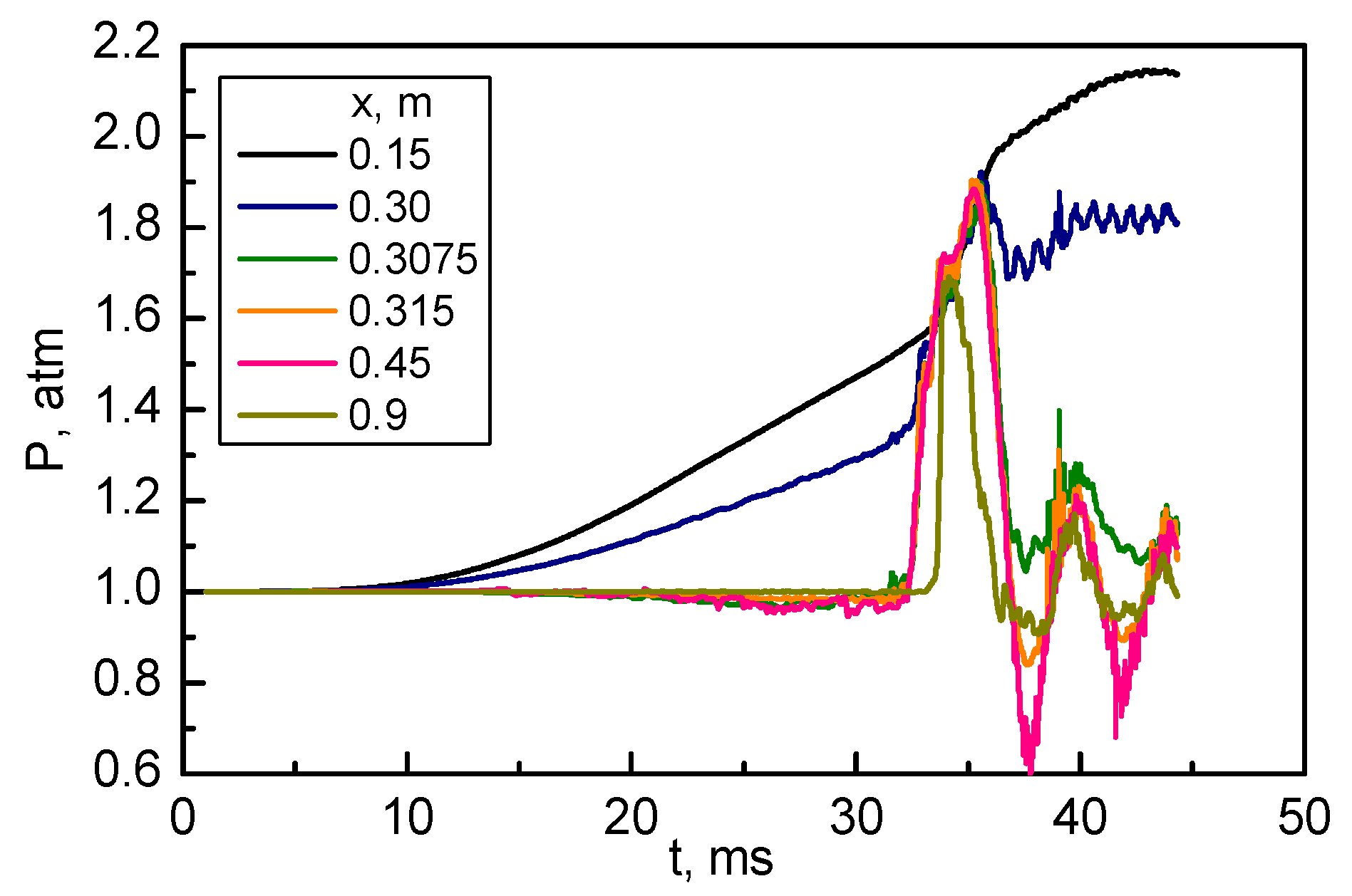
  • The main driving force for the gas flow in the current problem is the pressure developing due to thermal expansion of hot combustion products. The small size of the hole in the barrier makes pressure equalization between the channel parts rather slow, which significantly affects the flow field and flame propagation in the channel.
  • When ignition occurs in the closed channel part, pressure is rising in that part, and pressure drop develops across the barrier, accelerating the gas through the hole connecting the channel parts. Upon ignition in the open channel part, combustion products can flow out of the channel freely, and no significant pressure drop between the channel parts develops until the flame penetrates the closed part.
  • The main differences in between cases 1 and 2 are attributed to the direction of flame propagation coinciding with or opposite to the flow direction around the hole.
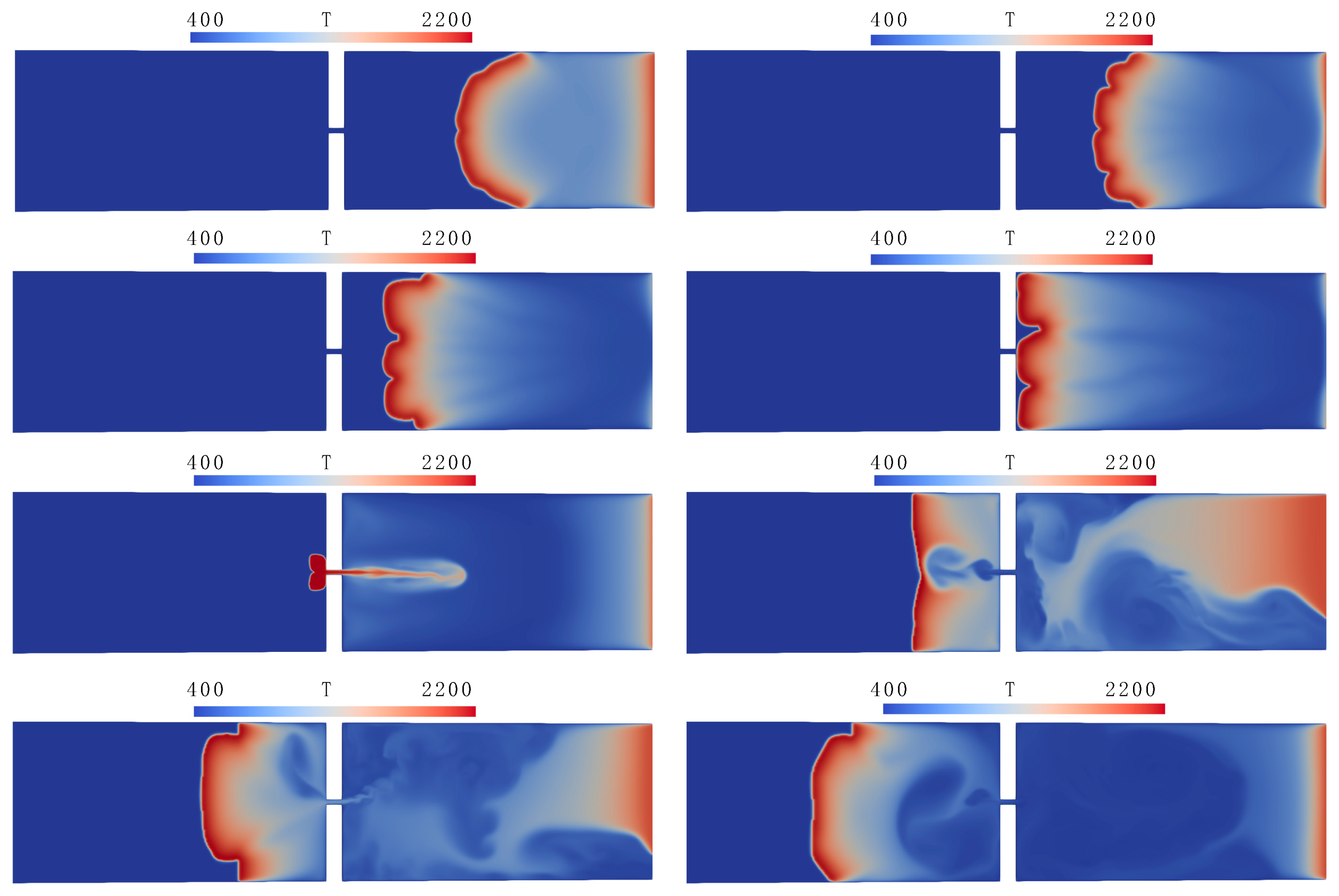
  • Transition of combustion from the closed part of the channel to the open one occurs much more intensively due to the piston effect of pressure difference. The fast gas jet issuing into the unreacted gas causes its turbulization and faster flame propagation behind the obstacle. This effect is not unique to Hele–Shaw cell channels; it was also obtained in a cylindrical vessel divided by a perforated plate [30].
  • An important consequence is that penetration of hot gases (both reacting zone and hot combustion products) from the closed part of the channel into the open one occurs due to the rapid “pushing” of the gas through the hole, while in the opposite case, flame propagation through the hole occurs over a practically immobile mixture. Therefore, flame penetration can occur for narrower holes than predicted by the classical theory of the thermal limits for combustion in pipes, where the possibility of flame propagation depends on the balance of heat release and heat loss to the cold walls of the pipe [3].
  • The previous conclusion may be important from the fire safety point of view: flame exhaust through small holes, leaks, and cracks can provide a mechanism for faster fire spread between compartments than the mechanism of conductive heating through partition walls.

Author Contributions

Conceptualization and methodology, S.Y., O.S. and M.A.; experiments, O.S. and M.A.; numerical simulations, S.Y.; data analysis, S.Y., O.S. and M.A.; writing—original draft preparation, O.S. and M.A.; writing—review and editing, S.Y., O.S. and M.A. All authors have read and agreed to the published version of the manuscript.

Funding

This research was supported by the Ministry of Science and Higher Education of Russia, agreement No. 075-15-2020-806.

Data Availability Statement

Not applicable.

Conflicts of Interest

The authors declare no conflict of interest. The funders had no role in the design of the study; in the collection, analyses, or interpretation of data; in the writing of the manuscript; or in the decision to publish the results.

References

  1. Bychkov, V.V.; Liberman, M.A. Dynamics and stability of premixed flames. Phys. Rep. 2000, 325, 115–237. [Google Scholar] [CrossRef]
  2. Matalon, M. Intrinsic flame instabilities in premixed and nonpremixed combustion. Annu. Rev. Fluid Mech. 2007, 39, 163–191. [Google Scholar] [CrossRef]
  3. Zeldovich, Y.B.; Barenblatt, G.I.; Librovich, V.B.; Makhviladze, G.M. The Mathematical Theory of Combustion and Explosions; Consultants Bureau: New York, NY, USA, 1985. [Google Scholar]
  4. Clanet, C.; Searby, G. On the “Tulip Flame” phenomenon. Combust. Flame 1996, 105, 225–238. [Google Scholar] [CrossRef]
  5. Shchelkin, K.I.; Troshin, Y.K. Non-stationary phenomena in the gaseous detonation front. Combust. Flame 1963, 7, 143–151. [Google Scholar] [CrossRef]
  6. Lee, J.H.S.; Moen, I.O. The mechanism of transition from deflagration to detonation in vapor cloud explosions. Prog. Energy Combust. Sci. 1980, 6, 359–389. [Google Scholar] [CrossRef]
  7. Shimo, M.; Heister, S.D. Schlieren visualization of multicyclic flame acceleration process in valveless pulsed detonation combustors. Combust. Sci. Technol. 2008, 180, 1613–1636. [Google Scholar] [CrossRef]
  8. Johansen, C.; Ciccarelli, G. Visualization of the unburned gas flow field ahead of an accelerating flame in an obstructed square channel. Combust. Flame 2009, 156, 405–416. [Google Scholar] [CrossRef]
  9. Johansen, C.; Ciccarelli, G. Numerical simulations of the flow field ahead of an accelerating flame in an obstructed channel. Combust. Theory Model. 2010, 14, 235–255. [Google Scholar] [CrossRef]
  10. Boeck, L.R.; Lapointe, S.; Melguizo-Gavilanes, J.; Ciccarelli, G. Flame propagation across an obstacle: OH-PLIF and 2-D simulations with detailed chemistry. Proc. Combust. Inst. 2017, 36, 2799–2806. [Google Scholar] [CrossRef]
  11. Ugarte, O.J.; Bychkov, V.; Sadek, J.; Valiev, D.; Akkerman, V. Critical role of blockage ratio for flame acceleration in channels with tightly spaced obstacles. Phys. Fluids 2016, 28, 093602. [Google Scholar] [CrossRef]
  12. Feng, X.; Huang, X. Influence of variable blocking ratio on DDT process. Energies 2022, 15, 7706. [Google Scholar] [CrossRef]
  13. Guo, B.; Gao, J.; Hao, B.; Ai, B.; Hong, B.; Jiang, X. Experimental and numerical study on the explosion dynamics of the non-uniform liquefied petroleum gas and air mixture in a channel with mixed obstacles. Energies 2022, 15, 7999. [Google Scholar] [CrossRef]
  14. Gao, J.; Ai, B.; Hao, B.; Guo, B.; Hong, B.; Jiang, X. Effect of obstacles gradient arrangement on non-uniformly distributed LPG–Air premixed gas deflagration. Energies 2022, 15, 6872. [Google Scholar] [CrossRef]
  15. Joulin, G.; Sivashinsky, G.I. Influence of momentum and heat losses on the large-scale stability of quasi-2D premixed flames. Combust. Sci. Technol. 1994, 98, 11–23. [Google Scholar] [CrossRef]
  16. Wongwiwat, J.; Gross, J.; Ronney, P.D. Flame Propagation in Narrow Channels at Varying Lewis Number. In Proceedings of the 25th ICDERS, Leeds, UK, 2–7 August 2015; pp. 3–8. [Google Scholar]
  17. Al-Sarraf, E.; Almarcha, C.; Radisson, B.; Denet, B.; Quinard, J. Flame Instability in a Hele-Shaw Cell: Thickness Effect. In Proceedings of the 8th European Combustion Meeting ECM2017, Dubrovnik, Croatia, 18–21 April 2017; pp. 357–360, ISBN 978-953-59504-1-7. [Google Scholar]
  18. Almarcha, C.; Radisson, B.; Al Sarraf, E.; Villermaux, E.; Denet, B.; Quinard, J. Interface dynamics, pole trajectories, and cell size statistics. Phys. Rev. E 2018, 98, 030202. [Google Scholar] [CrossRef]
  19. Tayyab, M.; Radisson, B.; Almarcha, C.; Denet, B.; Boivin, P. Experimental and numerical Lattice-Boltzmann investigation of the Darrieus–Landau instability. Combust. Flame 2020, 221, 103–109. [Google Scholar] [CrossRef]
  20. Alexeev, M.; Borisov, V.; Semenov, O.; Yakush, S. Instability of Laminar Flame Propagation in a Narrow Gap between Parallel Plates. In Proceedings of the 8th European Combustion Meeting ECM2017, Dubrovnik, Croatia, 18–21 April 2017; pp. 2034–2039, ISBN 978-953-59504-1-7. [Google Scholar]
  21. Alexeev, M.M.; Semenov, O.Y.; Yakush, S.E. Experimental study on cellular premixed propane flames in a narrow gap between parallel plates. Combust. Sci. Technol. 2018, 191, 1256–1275. [Google Scholar] [CrossRef]
  22. Jang, H.J.; Jang, G.M.; Kim, N. Il Unsteady propagation of premixed methane/propane flames in a mesoscale disk burner of variable-gaps. Proc. Combust. Inst. 2019, 37, 1861–1868. [Google Scholar] [CrossRef]
  23. Veiga-López, F.; Martínez-Ruiz, D.; Fernández-Tarrazo, E.; Sánchez-Sanz, M. Experimental analysis of oscillatory premixed flames in a hele-shaw cell propagating towards a closed end. Combust. Flame 2019, 201, 1–11. [Google Scholar] [CrossRef]
  24. Radisson, B.; Piketty-Moine, J.; Almarcha, C. Coupling of vibro-acoustic waves with premixed flame. Phys. Rev. Fluids 2019, 4, 121201. [Google Scholar] [CrossRef]
  25. Fernández-Galisteo, D.; Kurdyumov, V.N.; Ronney, P.D. Analysis of premixed flame propagation between two closely-spaced parallel plates. Combust. Flame 2018, 190, 133–145. [Google Scholar] [CrossRef]
  26. Borisov, V.E.; Yakush, S.E.; Sysoeva, E.Y. Numerical simulation of cellular flame propagation in narrow gaps. Math. Model. Comput. Simul. 2022, 14, 755–770. [Google Scholar] [CrossRef]
  27. Veiga-López, F.; Kuznetsov, M.; Martínez-Ruiz, D.; Fernández-Tarrazo, E.; Grune, J.; Sánchez-Sanz, M. Unexpected propagation of ultra-lean hydrogen flames in narrow gaps. Phys. Rev. Lett. 2020, 124, 174501. [Google Scholar] [CrossRef]
  28. Chen, D.; Ma, H.; Shen, Z.; Yao, Y. Investigation of the quenching of methane-air deflagration in narrow parallel channels. Process Saf. Prog. 2020, 39, e12126. [Google Scholar] [CrossRef]
  29. Lu, Y.; Guo, P.; Wang, Z.; Wang, X.; Chen, Y. Investigation on quenching characteristics of parallel narrow channels for deflagration flames. Fire Mater. 2023. [Google Scholar] [CrossRef]
  30. Wei, H.; Li, K.; Zhao, J.; Zhou, L. Experimental investigation on the propagation of flow and flame in a confined combustion chamber equipped with a single-hole perforated plate. Int. J. Hydrogen Energy 2020, 45, 32589–32597. [Google Scholar] [CrossRef]
  31. Ju, Y.; Maruta, K. Microscale combustion: Technology development and fundamental research. Prog. Energy Combust. Sci. 2011, 37, 669–715. [Google Scholar] [CrossRef]
  32. Escofet-Martin, D.; Chien, Y.C.; Dunn-Rankin, D.; Dzieminska, E.; Hayashi, A.K.; Hanada, S. Flame propagation in a narrow closed channel: Effects of aspect ratios, blockage ratio, and mixture reactivity on flame speed and pressure dynamics. Combust. Sci. Technol. 2020, 192, 986–996. [Google Scholar] [CrossRef]
  33. Poinsot, T.; Veynante, D. Theoretical and Numerical Combustion, 2nd ed.; R.T. Edwards, Inc.: Philadelphia, PA, USA, 2005. [Google Scholar]
  34. Warnatz, J.; Maas, U.; Dibble, R.W. Combustion. Physical and Chemical Fundamentals, Modeling and Simulation, Experiments, Pollutant Formation; Springer: Berlin/Heidelberg, Germany, 2006. [Google Scholar]
  35. Bramlette, R.B.; Depcik, C.D. Review of propane-air chemical kinetic mechanisms for a unique jet propulsion application. J. Energy Inst. 2020, 93, 857–877. [Google Scholar] [CrossRef]
  36. Westbrook, C.K.; Dryer, F.L. Simplified reaction mechanisms for the oxidation of hydrocarbon fuels in flames. Combust. Sci. Technol. 1981, 27, 31–43. [Google Scholar] [CrossRef]
  37. CERFACS Mechanisms. Available online: https://www.cerfacs.fr/cantera/docs/mechanisms/propane-air/1S_C3H8_CM1/1S_C3H8_CM1.cti (accessed on 20 November 2022).
  38. OpenFOAM, Version 2106. Available online: https://www.openfoam.com (accessed on 20 November 2022).
  39. Cantera, Version 2.5.1. Available online: https://cantera.org (accessed on 20 November 2022).
  40. Zhou, D.; Zhang, H.; Yang, S. A robust reacting flow solver with computational diagnostics based on OpenFOAM and Cantera. Aerospace 2022, 9, 102. [Google Scholar] [CrossRef]
  41. Yakush, S.E.; Korobeinichev, O.P.; Shmakov, A.G.; Bolshova, T.A.; Trubachev, S.A. A reduced kinetic scheme for methyl methacrylate gas-phase combustion. Combust. Theory Model. 2022, 1–14. [Google Scholar] [CrossRef]
Figure 1. Sketch of the experimental facility: top and bottom acrylic plates (1), side walls of the channel (2), obstacle (3), flame front (4), spark electrodes (5), inlet nozzle (6), mixture supply hose (7), ignition coil (8), flame extinguisher (9), valve (10), gas volume meter (11), two-tank displacement gas meter (12), high-speed video or photo camera (13).
Energies 16 01516 g001
Figure 2. Computational domain and fragment of Cartesian mesh.
Energies 16 01516 g002
Figure 3. Flame penetration through a hole from the closed (right) to open (left) channel part: experiment in a channel with distance between plates of 9 mm, 6.5% propane–air mixture.
Energies 16 01516 g003
Figure 4. Flame penetration through a hole: temperature distributions in the symmetry plane z = 0 at times 10, 20, 30, 32, 33, 33.5, 36, and 40 ms (top to bottom, left to right).
Energies 16 01516 g004
Figure 5. Longitudinal ( x ) velocity component distributions in the symmetry plane z = 0 at times 10, 20, 30, 32, 33, 33.5, 36, and 40 ms.
Energies 16 01516 g005
Figure 6. Pressure (a), longitudinal velocity (b), and temperature (c) distributions along the symmetry line at the indicated times (boundaries of the obstacle are shown by vertical dashed lines).
Energies 16 01516 g006
Figure 7. Pressure time histories at six positions on the symmetry line: middle of the closed chamber (0.15 m), entrance, middle, and exit of the hole in the obstacle (0.3, 0.3075, and 0.315 m), middle of the open chamber, and near the exit (0.9 m).
Energies 16 01516 g007
Figure 8. Flame penetration through a hole from the open (left) to closed (right) channel part: experiments in a channel with distance between plates of 9 mm, 5.5% propane–air mixture.
Energies 16 01516 g008
Figure 9. Flame penetration through a hole from open to closed channel part, temperature distributions in the symmetry plane z = 0 at times 100, 300, 500, 700, 900, 1100, 1200, and 1560 ms (top to bottom, left to right).
Energies 16 01516 g009
Figure 10. Longitudinal ( x ) velocity component distributions in the symmetry plane z = 0 at times 500, 900, 1100, and 1560 ms (top to bottom, left to right).
Energies 16 01516 g010
Figure 11. Longitudinal velocity (a) and temperature (b) distributions along the symmetry line at the indicated times (boundaries of the obstacle are shown by vertical dashed lines).
Energies 16 01516 g011
Disclaimer/Publisher’s Note: The statements, opinions and data contained in all publications are solely those of the individual author(s) and contributor(s) and not of MDPI and/or the editor(s). MDPI and/or the editor(s) disclaim responsibility for any injury to people or property resulting from any ideas, methods, instructions or products referred to in the content.

