Article

Evaluation and Solution Suggestions for Engineering and Workmanship Failures during Design and Installation of Solar Power Plants

1
Department of Electronics and Automation, Sivas Cumhuriyet University, Sivas 58140, Turkey
2
Division of Engineering, Saint Mary’s University, Halifax, NS B3H 3C3, Canada
*
Author to whom correspondence should be addressed.
Energies 2023, 16(3), 1457; https://doi.org/10.3390/en16031457
Submission received: 31 December 2022 / Revised: 21 January 2023 / Accepted: 27 January 2023 / Published: 1 February 2023
(This article belongs to the Special Issue Renewable Energy Microgrids for the Future of Electrical Grid)

Abstract

:
Among the various renewable energy generation systems, the solar photovoltaic occupies a leading position today due to its simple structure. However, increasing the efficiency of solar photovoltaic systems is a highly researched topic. In this study, possible connection failures in maximum power inverters and other failures, which decrease the efficiency in solar power plants, are examined. Furthermore, the possible consequences of these losses and their effects on the performance of solar power plants are explained. Some missing-failure processes were identified and corrected in the field analysis of the solar power plant in Turkey. Detected missing failures include connection failures of solar inverters, incorrect network configuration of camera system, fixing lighting time settings. The inverter string connection failure made during the projecting and assembly phase was eliminated and the maximum output was determined as 584.25 kW after the DC string arrangement. An increase of approximately 10% was achieved in production. In the project and application phase, the connection details of the inverters should be drawn and given to the field application personnel as a full-fledged project. In this way, incorrect connections that are not shown in the project and made in the field are prevented. This ensures that the installed power plant operates more efficiently, and the budgetary payback period of the investments made is shortened.

1. Introduction

Considering the consumption of fossil fuels and the damage they cause to the environment, the interest in renewable energy is increasing day by day. The rapid increase in the development of renewable energy has increased the need of countries for sustainable energy, as seen all over the world in recent years. The integration of renewable energy generation systems such as solar photovoltaic (PV) arrays, micro wind turbines, biomass power plants and fuel cells into the electricity grid has increased. However, the natural intermittent nature of renewable energy has brought negative effects on the grid. The main disadvantages are voltage increase, power quality, protection coordination and system stability. Therefore, there is a need for more controllable, reliable, configurable and smart energy distribution systems. As a result, microgrids have emerged, and more ideal working conditions have been provided with safer uninterruptible power supply, reduced losses and increased efficiency [1].
Microgrids are divided into alternative current (AC) and direct current (DC) microgrids. DC microgrids offer various benefits on AC systems such as voltage, synchronization and frequency regulation issues. DC microgrids allow twice as much power flow as AC systems as they improve the system in terms of reliability and power quality. Initially, they increased system efficiency, provided flexibility in operation, reduced power conversion stages and provided easier integration of loads [2]. With smart homes, fast charging stations, hybrid energy systems and renewable energy parks, the need for microgrids has started to increase [3].
Solar photovoltaic (PV) micro-grid, compared to other renewable sources, is in the leading position today due to its simple structure. However, according to other sources, the solar panel system only converts 20–25% of solar radiation into electrical energy. Although photovoltaic energy seems to be a very good option considering cli-mate changes, the use of renewable energy systems depends on environmental conditions and time of day in terms of energy production [4]. It also faces challenges such as power balancing [5] and stability and reliability of the power supply, quality [6]. Increasing efficiency is an important issue of solar photovoltaic systems.
The efficiency of PV systems depends on the efficiency of its components, such as the PV module [7], the performance of the optimizer [8,9], the layout of the DC network [8,9] and the DC-AC inverter [10]. In large-scale applications, the overall efficiency of PV power plants is evaluated according to the design of the AC power grid, which consists of AC cables and power transformers.
In order to obtain maximum efficiency from a PV panel system, extensive research has been carried out for a long time to access the performance of the PV system and to explore various issues related to the effective use of the solar PV system [11]. In recent studies, the accuracy of the active power calculation based on the output waveform continues to be evaluated [12]. In addition, discussions about the varied nature of the PV panel system and its suitability in locations are still ongoing [13]. The efficiency of the PV system can be increased by using power electronic devices together with the maximum power point controller. The extraction of the maximum usable power from a PV module is performed by the maximum power point tracking (MPPT) controller. The efficiency of the PV system can be increased significantly by using the MPPT controller [11].
In some studies, to solve the serial connection problem in the PV power generation system, a central MPPT with an array current diverter has been proposed. The system proposed here is able to effectively separate each PV module from the rest of the array, making it insensitive to changes in the array current [14]. Generally, the MPPT control system is concerned with extracting the maximum power from sunlight, while the current controller is mainly designed to optimize the inverter power to feed the power grid [15].
In order to realize the maximum utilization of the PV array, MPPT is of great importance in PV generation. Recently, many MPPT algorithms have been presented, varying in structural complexity, control accuracy, response time and cost [16]. Numerical simulations are performed to validate the proposed methods and eliminate the possibility of MPPT failure [17]. Other studies on the effect of energy losses due to faults on the PV plant energy balance are increasing day by day [18]. Technical risks and failures in PV projects can be included in components (modules, inverters, assembly structure, junction and distribution boxes, etc.) [19]. The effect of failures in solar PV panels on the production rate and efficiency continues to be investigated. Faults in a solar power plant (SPP) seriously affect the reliability and energy balance of the system. Therefore, the energy losses produced by the SPP directly depend on two main factors, which are plant failures and production inefficiencies in PV panels. Knowing the negative effects of energy losses in PV plants contributes to the optimization in maintenance and design and increases efficiency in power generation [20]. In addition, some studies present a graphical user interface for the proposed solar panel fault diagnosis system [21]. In this study, [21], possible inverter MPPT connection failures and other faults in SPPs are examined and the possible consequences of these losses and their effects on SPP performance are explained. The inverter MPPT string connection failure made during the projecting and installation phase was corrected, and the maximum production after the DC string arrangement was determined as 584.25 kW. Approximately 10% increase has been achieved in the production.
The remainder of this study is organized as follows: Solar inverters and important parameters to the most efficient/maximum outputs are described in Section 2. The experimental results and discussions are presented in Section 3. Conclusions are presented in the last section of this article.

2. Materials and Methods

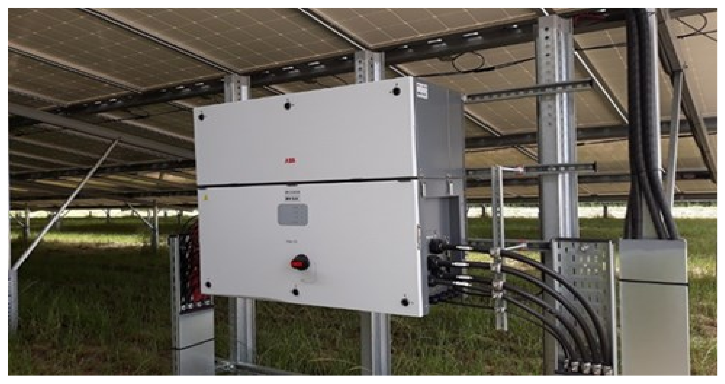
2.1. Solar Inverters

Solar inverter is a converter that converts direct current (DC) electrical energy produced by PV panels in solar power plants into alternative current (AC) electrical energy [22]. Thanks to the inverter, the voltage, frequency and quality of the electrical energy to be used by the consumer or provided to the utility network is brought to the desired level. Moreover, the technological and digital features of solar inverters help in many aspects such as monitoring the power plant, energy efficiency, security, integration with future technologies (energy storage, electric vehicle charging stations, smart home applications, etc.). The most important factor when choosing a solar inverter brand for a solar project is to plan the useful life of the investment for at least 20 years in the long term. For this reason, in addition to the technical advantages offered by the brand, its total installed power, annual production capacity, warranty conditions, product diversity, the company’s financial situation, the importance and references it attaches to innovation are just a few of the important criteria. Another very important criterion is the service of the brand [23]. Widespread service network is very important for the plant to continue to operate flawlessly after the project and for the useful life of the investment. In this study, an ABB PVS 100 model solar inverter, shown in Figure 1, is used in the solar plant. The PVS100 inverter model max. per MPPT. output power is 17.5 kW. On the panel side, each string output power is 6.2 kW, so there is 24.8 DC power.
With the right workmanship and the right material selection, the fire risk is almost non-existent in the SPPs. This means that fires caused by SPP can almost be ignored. Solar inverters are extremely reliable products. Inverters suffer from a decrease in power with an increase in temperature. Power derating is the phenomenon of inverters reducing their own power to prevent the overheating of their components. For this reason, the operating temperatures of the inverter should definitely be taken into account when choosing a solar inverter.
The number of PV modules in an array depends on the PV module’s open-circuit voltage (VOC), short-circuit current (ISC), and the highest current and voltage values that the inverter DC inputs can safely withstand. An array design should be made according to the lowest and highest temperature values of that region. The amount of sunlight coming to the solar panels changes constantly during the day. Moreover, due to factors such as cloudiness, temperature and dust, the energy received from the sun constantly changes. This momentarily changing power cannot be given directly to the load. This force needs to be regulated and stabilized. At this point, MPPT transfers the power to the network or the storage at the point where the instantaneously produced power is maximum. Another important issue is that if the MPPT string connection of the solar inverters is not carried out correctly, the power taken from the inverter and the production decrease. Solar inverters can be examined in three main categories as string inverter, central inverter and micro inverter.

2.1.1. String Inverters

Solar panels connected in series, in the form of a string, are carried to the string inverter with a DC cable. String inverter technology has been used for a long time. It is a very reliable tried and verified technology, but they may not be suitable for every project. Although modern solar technology allows panels to continue producing power even if part of the panel is shaded, standard string inverters can only optimize power output at the string level. One of the advantages of string inverters is that the intervention in string inverters is quick and easy. When there is a problem with the inverter, it can be quickly solved with minimal downtime. String inverters are easy to install and labor costs are much more affordable. Wiring is simple, which minimizes possible cable failures [24].

2.1.2. Central Inverters

Central inverters, on the other hand, are the types of inverters where the energy flow is made from a single place from the center. They are especially preferred in power plants spread over a wide area or in large industrial facilities. In central inverters, solar panels are combined in junction boxes before being fed to the inverter. These connections then reach the central inverter [25].

2.1.3. Micro Inverters

Micro inverters represents a fast and practical solution, especially in small power plants. The major difference between micro inverters and string inverters is that a solar panel installation with a micro inverter typically has the same number of micro inverters as solar panels. This makes micro inverters a more expensive and difficult system to implement, especially when power plant power grows [26].

2.2. Important Parameters to the Most Efficient/Maximum Outputs from the Solar Inverter

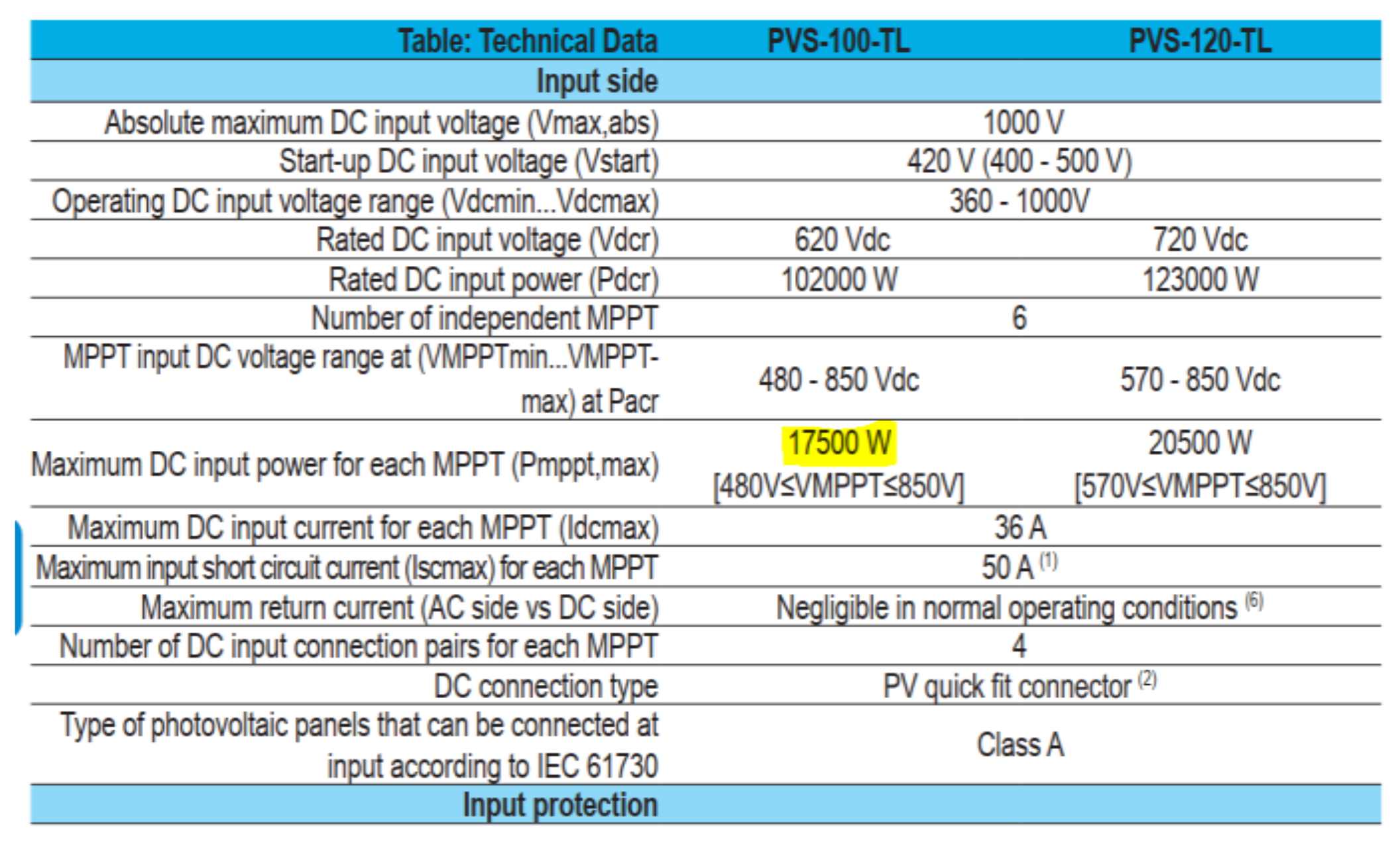
2.2.1. MPPT and Maximum DC Input Voltage

The maximum DC input voltage limits the maximum open circuit voltage of the PV array. The maximum open circuit voltage of the array should not exceed the maximum DC input voltage at the lowest ambient temperature at the project location. Currently, three voltage limits are mainly used on two lines, and they are: 1000 V, 1100 V and 1500 V. In the calculation of the maximum DC input voltage, the open circuit voltage of the array is used and these voltage values are decisive for the project designers. If these limit values are exceeded, inverters may be damaged [27].

2.2.2. Starting Voltage

Before the inverter starts working, the connected strings are in an open circuit state and the string voltage is high. When the inverter starts generating, the connected strings will become a closed circuit and the string voltage will drop. The starting voltage of the inverter is higher than the minimum operating voltage of the inverter. In this way, when the string voltage changes from open circuit to closed, the inverter can continue production without being disabled [28].

2.2.3. Minimum Input Voltage

After the inverter starts, it continues to operate within a certain voltage range. The smallest voltage in this range is the minimum DC input voltage. The inverter continues its production despite loss of efficiency at these voltage levels.

2.2.4. Operating Voltage Range

The operating voltage range is designed for the inverter to adapt to changing string voltages. Array voltage changes with irradiance and temperature changes. The number of panels, connected in series, is also designed in accordance with the inverter operating range according to the special conditions of the project. If the string voltage is within the operating voltage range, the inverter continues its normal operation. The wider the operating voltage range of the inverter, the more project-specific design flexibility it provides.

2.2.5. Maximum Power Range

The MPPT system meticulously monitors the instantaneous and variable energy production in the solar panel, thanks to highly developed algorithms, and always ensures the highest efficiency, in other words, the highest power gain. The maximum power point (MPP) voltage range is the inverter’s ability to produce the full rated power within this voltage range. The inverter will be able to give full power when it has the optimum operating voltage and maximum input current, and it will only be able to achieve this in the full load voltage range. If the input voltage is outside these values (down or above), the inverter’s output power will decrease. The highest efficiency is achieved in this voltage range. For this reason, the MPP range is very important and is among the first features to be looked at in inverters. The string voltage should also be designed within the full load voltage range whenever possible.

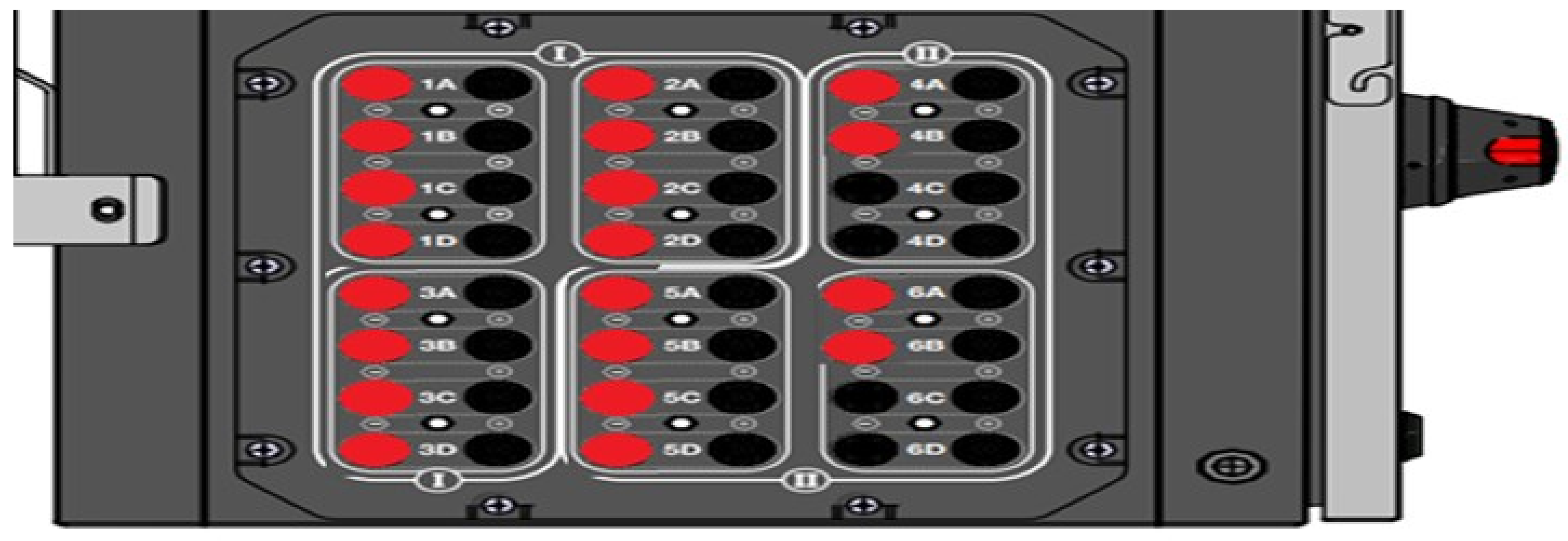
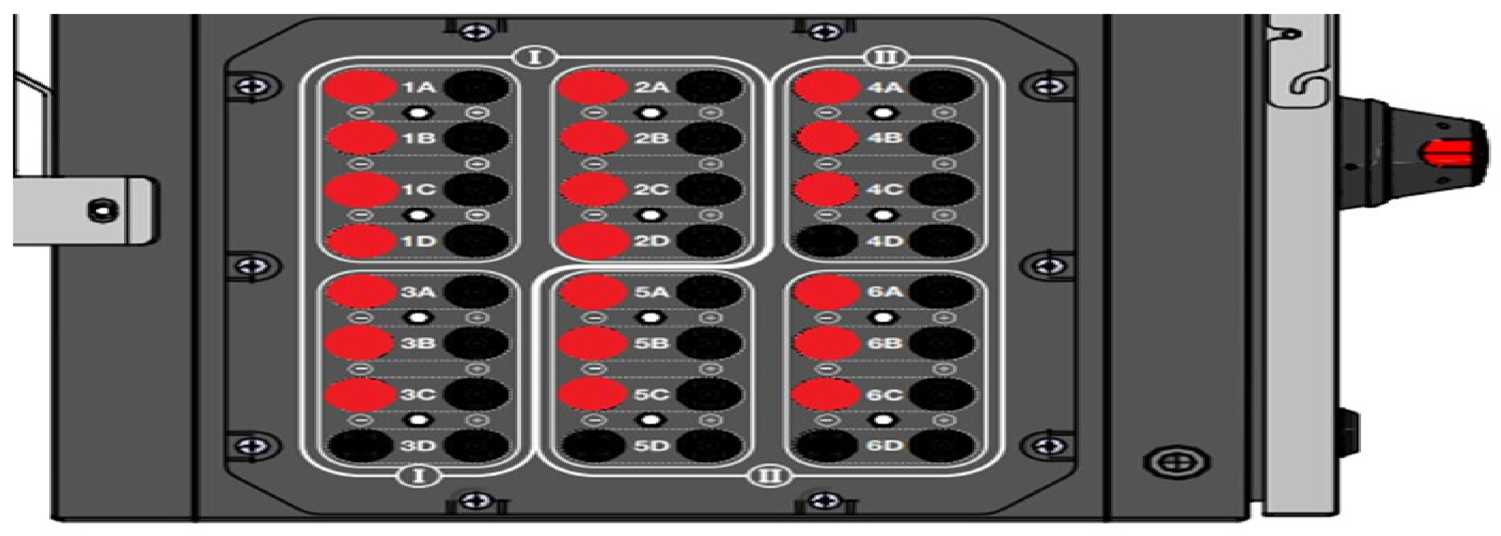
2.2.6. MPPT String Connection Failures

String connection is important for an inverter. The string input of each inverter should be checked. If the connection is made without leaving the string inputs in each MPPT blank, 100% efficiency is obtained from the inverter output.

3. Experimental Results and Discussion

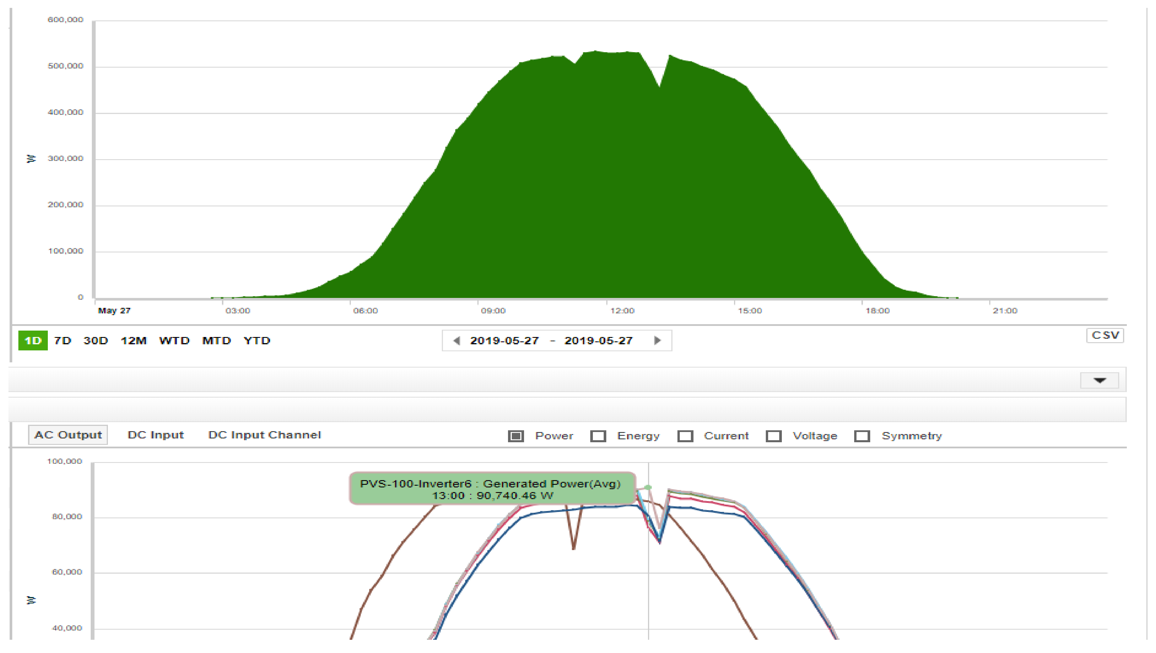
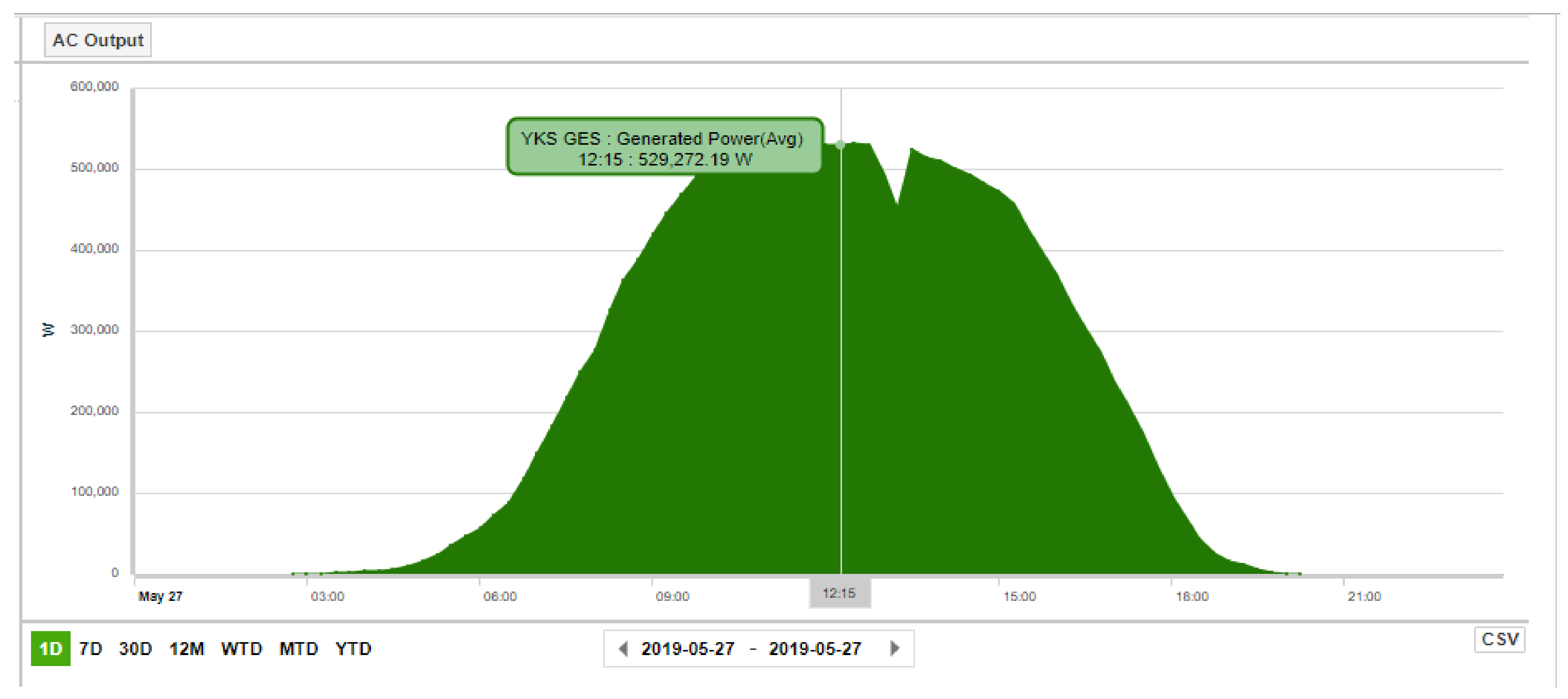
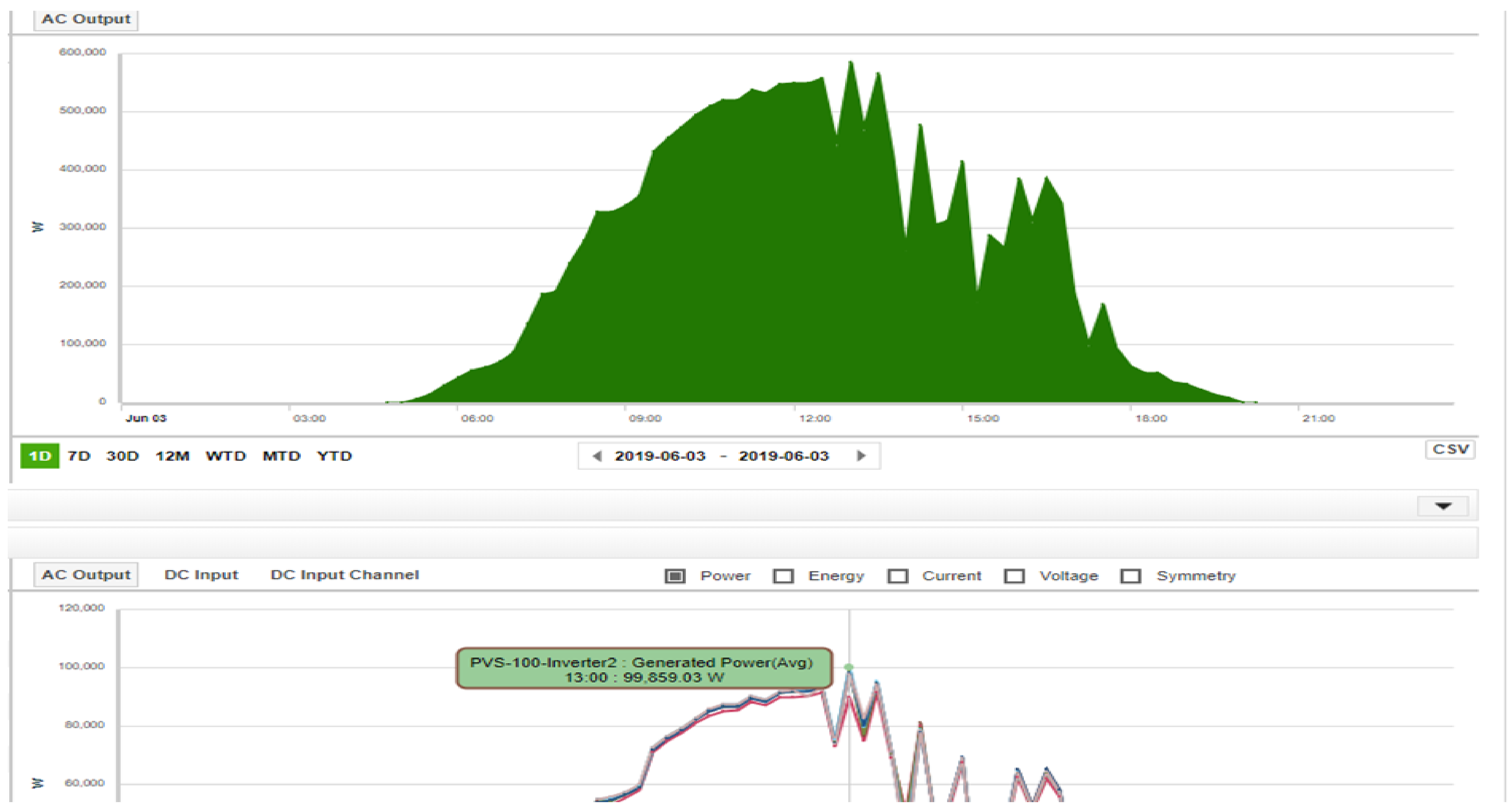
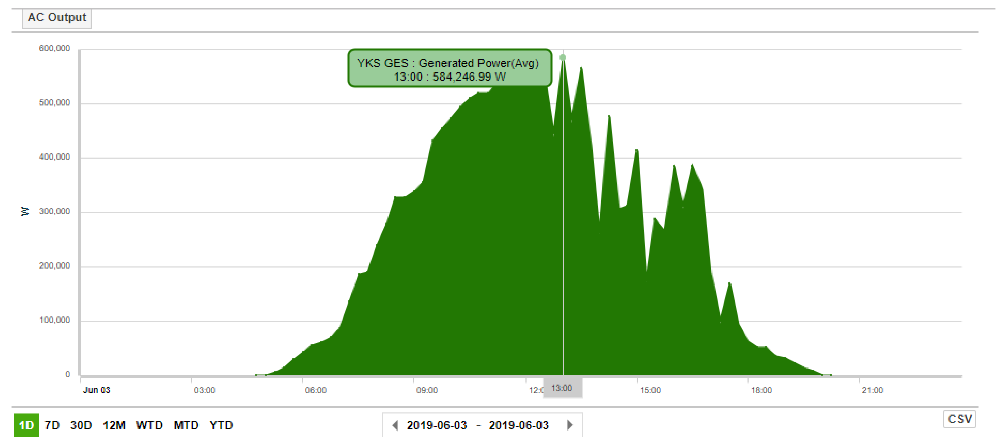
3.1. MPPT Connection Failures of Solar Inverters

In this study, in the field analysis of the solar power plant in Amasya, Turkey, some incomplete-failure processes were detected and corrected. They were caused by mistakes made during the installation and projecting phase of the solar power plants. The maximum power at each MPPT input of ABB PVS100 inverters is shared in the catalog as 17.5 kW, as shown in Figure 2. Due to this value, the maximum operating power is calculated as 105 kW for six inverters.
The power of each series in the project is calculated as 6.05 kW according to the power of 22 panels (275 W). As seen in Figure 3, the number of MPPTs in each inverter is six, and the number of string inputs in each MPPT is four. As a result, there are 24 string entries in total. The number of strings determined during the installation and projecting phases is 20 for each inverter. As shown in Figure 3, each MPPT is numbered from 1 to 6 and the string name of each MPPT is lettered from A to D. The faulty connection is that starting from 1A, four strings of the first MPPTs were connected, and only two strings of the last two MPPTs were connected. According to this connection, each inverter will be able to produce a maximum of 17.5 kW per string for four strings and for 12.1 kW per string for two strings for a total power of 94.2 kW. This is the DC maximum power; the maximum it could produce was 90.74 kW on the day of 27 May 2019. Figure 4 shows the maximum inverter output value. The graphs show the power produced by each inverter. In inverter, the maximum generated power can be seen in Figure 4.The maximum production value before DC string editing was determined as 529.28 kW and is shown in Figure 5.
In light of these determinations, the maximum output power cannot be obtained from the inverter due to the MPPT input of the solar inverter left blank. The inverter had 24 string inputs. There were 20 MPPT inputs of the inverters in this field, MPPT No. 6 was left blank during the installation phase. There were four string inputs in each MPPT and MPPT No. 1 and 2 were not touched in this study. A string was removed from MPPT no. 3, 4, and 5 and attached to string inputs numbered 1, 2, and 3 to the MPPT no 6. This MPPT string arrangement study was carried out on all the inverters in the field, thus increasing the total power and energy amount in the field by 5–10%. This is a situation that is overlooked during the installation and design phase. The last string connection of the inverters was as in Figure 6. Thus, the MPPT production capacity and total field production capacity have increased. According to this connection, it will be able to produce a maximum power of 100.5 kW for six inverters, according to the maximum power output of 17.5 kW for each inverter. However, while the panel DC power in the first and second MPPTs is calculated as 24.2 kW based on 6.05 kW over four strings, in the other third, fourth, fifth and sixth MPPTs, it is 18.15 kW according to 6.05 kW over three strings. As can be seen in Figure 7, the maximum output value of an inverter has increased to 99.86 kW. The maximum generation, after the DC string arrangement, was determined as 584.25 kW, as shown in Figure 8. An increase of approximately 10% has been achieved. Table 1 provides information about solar power plant characteristics, such as DC installed power, AC generation power, inverter brand model, of the field analysis at the unlicensed solar power plant belonging to ESKO Energy, located in Yağmur Village of Amasya Center. Table 2 gives information about the regular maintenance of the power plant parts, such as inverters, transformers and communications, in the field for 6 months, daily or weekly.
As a result of this study, approximately 1 year operating maintenance costs have been reduced thanks to the increase in the production. The positive reflection of these determinations in the fields also makes great contributions to the sustainable energy in developing countries such as Turkey.

3.2. Incorrect Network Configuration of the Camera System

Incorrect network settings between the camera system and the inverter monitoring system were detected and conveyed to the company that installed the camera system. With this arrangement, a stable communication infrastructure between the inverter and/or the field monitoring system has been provided. In addition, a second antenna was attached to the modems and signal level improvements were made.

3.3. Fixing the Lighting Time Settings

By updating the settings of the astronomical time relay with the technical personnel in the field, the lighting is switched off as soon as the sun rises, thus preventing unnecessary consumption during the production.

3.4. Other Improvements

Necessary configuration changes were made for the remote reading of the remote terminal unit (RTU) and energy quality recorder (EQR) in the automation infrastructure in the field, and necessary arrangements were made to have control and monitoring capability in the medium voltage (MV) section, which was established for the electricity distribution company. In addition, the waste DC fuse in the fifth inverter was replaced, and the DC string failure, which had one (1) production loss, was eliminated.

4. Conclusions

The capacity of photovoltaic power systems based on solar energy in Turkey shows a significant improvement day by day. At this stage of development, solar systems need to be tested on-site to ensure long-term high-quality PV power generation. It is very useful for evaluating the actual performance of the plant and diagnosing faults. In this study, failures occurring in Amasya/Turkey solar power plants were determined. It has been determined that these failures occur during the projecting and assembly stages. Possible inverter MPPT connection failures and other failures in SPPs were examined and the possible consequences of these losses and their effects on SPP performance were explained. The inverter MPPT string connection error made during the projecting and assembly phase was corrected and the maximum output after DC string arrangement was determined as 584.25 kW. With the inverter MPPT array arrangement and fast detection of possible malfunctions, approximately 10% improvement in the production can be achieved. In this study, solution suggestions for an efficiency in the production, failures and other failure problems are discussed. Sustainable renewable energy sources are gaining importance in developing countries such as Turkey. For a more sustainable energy source, the solar system and solar inverters require annual or semiannual maintenance and inspection. In addition, future research may include fault detection based on thermography images, computer vision and artificial intelligence.

Author Contributions

Conceptualization, H.B. and A.M.; formal analysis, H.B. and A.M.; investigation, H.B. and A.M; validation, H.B., data curation, H.B; writing—original draft preparation, H.B.; writing—review and editing, A.M. All authors have read and agreed to the published version of the manuscript.

Funding

This research received no external funding.

Data Availability Statement

The raw/processed data required to reproduce these findings cannot be shared at this time as the data also forms part of an ongoing study.

Conflicts of Interest

The authors declare no conflict of interest.

References

  1. Lidula, N.W.A.; Rajapakse, A.D. Microgrids research: A review of experimental microgrids and test systems. Renew. Sustain. Energy Rev. 2011, 15, 186–202. [Google Scholar] [CrossRef]
  2. Zhang, F.; Meng, C.; Yang, Y.; Sun, C.; Ji, C.; Chen, Y.; Yang, G. Advantages and challenges of DC microgrid for commercial building a case study from Xiamen university DC microgrid. In Proceedings of the IEEE First International Conference on DC Microgrids (ICDCM), Atlanta, GA, USA, 7 June 2015. [Google Scholar]
  3. Salomonsson, D.; Sannino, A.; Low-Voltage, D.C. Distribution System for Commercial Power Systems With Sensitive Electronic Loads. IEEE Trans. Power Deliv. 2007, 22, 1620–1627. [Google Scholar] [CrossRef]
  4. Jonaitis, A.; Gudzius, S.; Morkvenas, A.; Azubalis, M.; Konstantinaviciute, I.; Baranauskas, A.; Ticka, V. Challenges of integrating wind power plants into the electric power system: Lithuanian case. Renew. Sustain. Energy Rev. 2018, 94, 468–475. [Google Scholar] [CrossRef]
  5. Lorenz, C. Balancing reserves within a decabonized European electricity System in 2050—From market developments to model insights. In Proceedings of the 2017 14th International Conference on the European Energy Market (EEM), Dresden, Germany, 6–9 June 2017; pp. 1–8. [Google Scholar]
  6. El-Sayed, M.M.; El-Ela, A.A.A.; El-Sehiemy, R.A. Effect of photovoltaic system on power quality in electrical distribution networks. In Proceedings of the 2016 Eighteenth International Middle East Power Systems Conference (MEPCON), Cairo, Egypt, 27–29 December 2016; pp. 1005–1012. [Google Scholar]
  7. Nayan, M.F.; Ullah, S.M.S.; Saif, S.N. Comparative analysis of PV module efficiency for different types of silicon materials considering the effects of environmental parameters. In Proceedings of the 2016 3rd International Conference on Electrical Engineering and Information Communication Technology (ICEEICT), Dhaka, Bangladesh, 22–24 September 2016; pp. 1–6. [Google Scholar]
  8. Rauf, S.; Wahab, A.; Rizwan, M.; Rasool, S.; Khan, N. Application of Dc-grid for Efficient use of solar PV System in Smart Grid. Procedia Comput. Sci. 2016, 83, 902–906. [Google Scholar] [CrossRef]
  9. Sinapis, K.; Tsatsakis, K.; Dörenkämper, M.; Van Sark, W.G.J.H.M. Evaluation and Analysis of Selective Deployment of Power Optimizers for Residential PV Systems. Energies 2021, 14, 811. [Google Scholar] [CrossRef]
  10. Vignola, F.; Mavromatakis, F.; Krumsick, J. Performance of PV inverters. In Proceedings of the 37th ASES Annual Conference, San Diego, CA, USA, 3–8 May 2008. [Google Scholar]
  11. Pakkiraiah, B.; Durga Sukuma, G. Research Survey on Various MPPT Performance Issues to Improved the Solar PV System Efficiency. J. Sol. Energy 2016, 2016, 8012432. [Google Scholar] [CrossRef]
  12. Havrlík, M.; Libra, M.; Poulek, V.; Kouřím, P. Analysis of Output Signal Distortion of Galvanic Isolation Circuits for Monitoring the Mains Voltage Waveform. Sensors 2022, 22, 7769. [Google Scholar] [CrossRef] [PubMed]
  13. Saadi, A.; Moussi, A. Neural network use in the MPPT of photovoltaic pumping system. J. Renew. Energy ICPWE 2003, 4, 39–45. [Google Scholar]
  14. Kadri, R.; Gaubert, J.-P.; Champenois, G. Centralized MPPT with string current diverter for solving the series connection problem in photovoltaic power generation system. In Proceedings of the International Conference on Clean Electrical Power (ICCEP), Ischia, Italy, 10 October 2011. [Google Scholar]
  15. Ahmad, A.; Loganathan, R. Real-Time Implementation of Solar Inverter with Novel MPPT Control Algorithm for Residential Applications. Energy Power Eng. 2013, 5, 427–435. [Google Scholar] [CrossRef]
  16. Yang, Y.; Wen, H. Adaptive perturb and observe maximum power point tracking with current predictive and decoupled power control for grid connected photovoltaic inverters. J. Mod. Power Syst. Clean Energy 2019, 7, 422–432. [Google Scholar] [CrossRef]
  17. Chen, M.; Ma, S.; Wu, J.; Huang, L. Analysis of MPPT Failure and Development of an Augmented Nonlinear Controller for MPPT of Photovoltaic Systems under Partial Shading Conditions. Appl. Sci. 2017, 7, 95. [Google Scholar] [CrossRef] [Green Version]
  18. Lillo-Bravo, I.; González-Martínez, P.; Larrañeta, M.; Guasumba-Codena, J. Impact of Energy Losses Due to Failures on Photovoltaic Plant Energy Balance. Energies 2018, 11, 363. [Google Scholar] [CrossRef]
  19. David, M.; Jahn, U.; Tjengdrawira, C.; Theologitis, I.T. Technical Risks in PV Projects—Report on Technical Risks in PV Project Development and PV Plant Operation, Solar Bankability. 2018. Available online: http://www.solarbankability.org/fileadmin/sites/www/files/documents/D1.1_2.1_Technical_risks_in_PV (accessed on 20 September 2022).
  20. Tur, M.R.; Colak, İ.; Bayindir, R. Effect of Faults in Solar Panels on Production Rate and Efficiency. In Proceedings of the International Conference on Smart Grid (icSmartGrid), Nagasaki, Japan, 4 December 2018. [Google Scholar] [CrossRef]
  21. Hwang, H.R.; Kim, B.S.; Cho, T.H. Implementation of a Fault Diagnosis System Using Neural Networks for Solar Panel. Int. J. Control Autom. Syst. 2019, 17, 1050–1058. [Google Scholar] [CrossRef]
  22. Solanki, S.G.; Ramasamy, M.; Manzoor, S.; Ganesalingam, U.K.R. Design & Development for OFF grid Solar Inverter. In Proceedings of the IEEE 4th International Symposium in Robotics and Manufacturing Automation (ROMA), Perambalur, India, 10 December 2018. [Google Scholar] [CrossRef]
  23. Kratzenbergab, M.G.; Deschamps, E.M.; Nascimento, L.; Rütheb, R.; Zürn, H.H. Optimal photovoltaic inverter sizing considering different climate conditions and energy prices. Energy Procedia 2014, 57, 226–234. [Google Scholar] [CrossRef]
  24. Famoso, F.; Lanzafame, R.; Maenza, S.; Scandura, P.F. Performance comparison between micro-inverter and string-inverter Photovoltaic Systems. Energy Procedia 2015, 81, 526–539. [Google Scholar] [CrossRef]
  25. Tariq, M.S.; Butt, S.A.; Khan, H.A. Impact of module and inverter failures on the performance of central-, string-, and micro-inverter PV systems. Microelectron. Reliab. 2018, 88–90, 1042–1046. [Google Scholar] [CrossRef]
  26. Harb, S.; Kedia, M.; Zhang, H.; Balog, R.S. Microinverter and string inverter grid-connected photovoltaic system—A comprehensive study. In Proceedings of the IEEE 39th Photovoltaic Specialists Conference (PVSC), Tampa, FL, USA, 16 June 2013. [Google Scholar] [CrossRef]
  27. Visa, I.; Duta, A.; Moldovan, M.; Burduhos, B.; Neagoe, M. Solar Energy Conversion Systems in the Built Environment, 1st ed.; Green Energy and Technology (GREEN); Springer: Berlin/Heidelberg, Germany, 2020; pp. 186–226. [Google Scholar]
  28. Mayer, M.J.; Gróf, G. Techno-economic optimization of grid-connected, ground-mounted photovoltaic power plants by genetic algorithm based on a comprehensive mathematical model. Sol. Energy 2020, 202, 210–212. [Google Scholar] [CrossRef]
Figure 1. ABB PVS100 solar inverter.
Energies 16 01457 g001
Figure 2. ABB PVS100 inverter catalog.
Energies 16 01457 g002
Figure 3. The incorrect MPPT string connection in the inverter.
Energies 16 01457 g003
Figure 4. Maximum inverter output value before string connection.
Energies 16 01457 g004
Figure 5. Maximum production value before DC string arrangement.
Energies 16 01457 g005
Figure 6. The correct MPPT string connection in inverter.
Energies 16 01457 g006
Figure 7. The maximum inverter output value after string connection.
Energies 16 01457 g007
Figure 8. Maximum production value after DC string arrangement.
Energies 16 01457 g008
Table 1. Information of solar power plant.
Santral Name and LocationESKO Energy Production Inc.
Amasya Center Yagmur Village
DC-Installed Power1210 kW
AC-Generating Power990 kW
Inverter Brand ModelABB-PVS100
Number of Inverters10
Number of DC Summation Boards-
Panel Brand ModelHT Solar-Polycrystalline
Panel Power Number275 W-4400
MV-LV Transformer Brand ModelASTOR
MV-LV Transformer Power1250 kVA
MV Cell Brand ModelUlusoy
LoM Relay Make ModelABB CMUFD-Modbus
Transformer Protection Relay Brand ModelThytronic NA21
Rectifier Brand Model Other InformationPower Elektronic
Number and Power of Supplied Environmental Lighting3-SLDP Board
Security Building Feed StatusNo
Compensation Power and Auto/ConstantFixed 50 kVAR, disabled
Inverter Power Restriction RatioInv-1 is restricted to 80%.
Table 2. The regular maintenance data of the power plant.
Regular Maintenance for PV PanelPeriods
Electrical and Mechanical controls for carrier system and panels
Panel control (Thermal Drone)
Connector, solar cable and connection equipment control
6 months
Regular maintenance for Inverter
Cleaning and isolation of the inverter due to humidity, heat and dust, checking the filters
Physical condition and functionality check (for the Inverter and all auxiliary equipment)
Checking and cleaning of sensors (for inverter)
Inverter fault analysis by determining the source of faults
6 months
Regular maintenance for Low voltage, Transformer and Medium voltage
Control of LV panels (contactors, switches, fuses, terminals, sensors, etc. physical control, tightness checks and thermal measurements
General control and maintenance of MV cells (physical control of breaker, measurement transformer, disconnector and fuses)
System control (Compensation Board)
Thermal measurement and tightness control (Lighting panel, DC/AC Panel Control)
6 months
Regular maintenance for Communication
Remote monitoring and controlling SCADA Systemdaily
Maintenance and control of communication infrastructuremonthly
Regular maintenance for General
Control of MV and LV panels (control of door, lock mechanisms and barrier and movement mechanisms6 months
Control of indicator, warning and control buttons on MV and LV panels6 months
Visiting the sitemonthly
Planned Maintenance and Service (submission of detailed activity reports within 5 working days at the latest)weekly
Immediate response (team intervention within 24 hours by sending a team to the field to instantaneous malfunctions in the field)when necessary
Control of consumption facilities within the framework of the servicemonthly
SPP production performance reportmonthly
Disclaimer/Publisher’s Note: The statements, opinions and data contained in all publications are solely those of the individual author(s) and contributor(s) and not of MDPI and/or the editor(s). MDPI and/or the editor(s) disclaim responsibility for any injury to people or property resulting from any ideas, methods, instructions or products referred to in the content.

