1. Introduction
At the current level of economic development, mining companies are expected to reduce their production costs and thus increase their operational efficiency [
1,
2,
3,
4]. At the same time, lowering costs must not affect work safety [
5,
6,
7,
8]. This determines the need to increase the efficiency of machines [
9,
10,
11] as well as their reliability [
12,
13], and to reduce their energy intensity [
14,
15,
16]. In mining, the monitoring of machine work processes is gradually being introduced [
17,
18]. The aim of this monitoring is to reduce the cost of servicing the machines and to maintain the highest possible reliability. This can be achieved using the latest technologies [
19,
20,
21].
Continuous development is also needed due to deteriorating mining and geological conditions. Operating at ever-greater depths generates new challenges in the field of exploitation [
22,
23] and regarding the requirements for machines and devices [
24,
25]. It is necessary to develop and optimize the scope of applied technologies [
26,
27,
28], machine fleets [
29,
30,
31], as well as ways to combat natural hazards [
32,
33,
34]. For this purpose, bench testing [
35,
36,
37] and in situ testing [
38,
39,
40,
41] are carried out. They are complemented by model testing [
42,
43] and computer simulations [
44,
45,
46] based on mathematical algorithms [
47,
48,
49,
50,
51,
52,
53,
54,
55].
In hard coal mining, the development of powered roof-support complexes is crucial [
56,
57,
58,
59]. A longwall complex is a set of machines constituting the essential equipment of a mining wall. It is used to mechanize the process of mining, loading, and transporting the product. The interdependence of construction and movement characterizes machines in the wall complex. The primary function of the wall complex is to achieve the required performance while maintaining safety. The powered wall complex includes a powered roof support, a scraper conveyor and a mining machine. In this work, the authors focus mainly on the development of the powered roof support. Recent research on the development of powered roof supports can be found in [
60,
61,
62,
63].
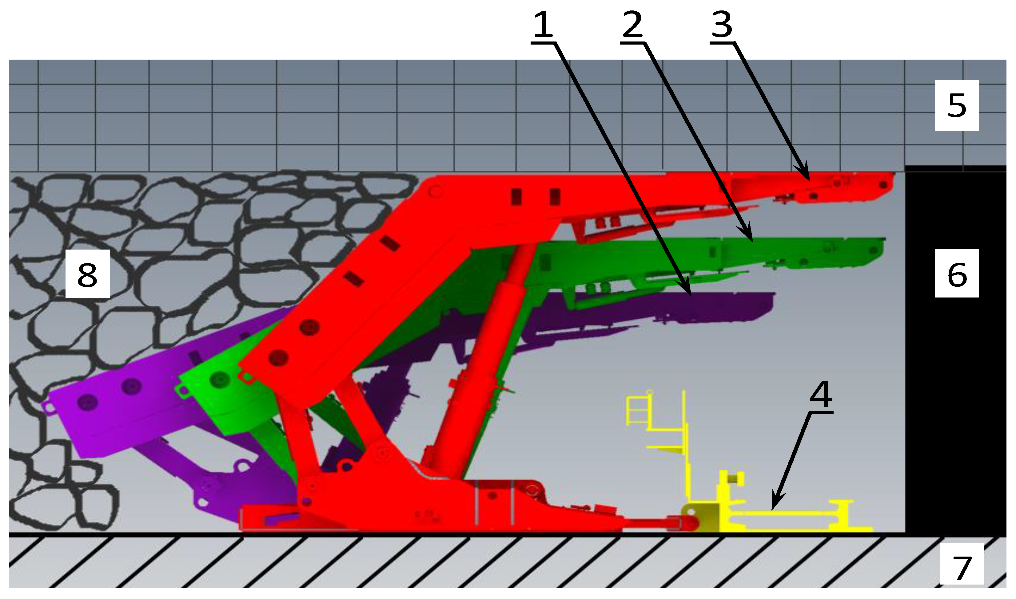
The powered roof support has two primary functions in the mining wall. It protects the roof of the excavation, ensuring the safety of operation. The second is to move the entire powered wall complex along the progress of the wall front. The operation of the powered roof support consists of repetitive cycles. Each cycle comprises the following stages: drawing off powered roof support, moving, spreading and securing the roof (
Figure 1). Withdrawing the powered roof-support section consists in lowering its height—so that the canopy loses contact with the excavation roof. Then it is possible to move the powered roof support section towards the coal. After moving the powered roof support, it is expanded between floor and roof of the excavation—so as to get the canopy in contact with the excavation roof. To ensure proper operation of the powered roof support, it is necessary to maintain the required load-capacity value. Load-carrying capacity is the force with which the support acts on the roof [
63,
64].
A powered roof support operates with three kinds of load capacity. Initial load capacity is obtained at the moment of expanding the powered roof support. After the powered roof support takes the pressure of roof rocks, it obtains working load capacity. However, at the maximum load-bearing value, the powered roof support reaches the nominal load capacity. Its value depends on the setting of the safety valves [
65]. For the powered roof support to perform its tasks well, its reliable operation is necessary. Internal leaks represent one of the significant problems in the operation of the powered roof support.
The formation of internal leakage in the racks of the powered roof support significantly affects the loss of working load capacity. The simplest way to minimize them is to remove the cause of the leak. This is usually done by replacing the affected components, which generates high costs. The powered roof support usually consists of about 150–160 sections. The wall’s extraction and the impact of the rock mass also affect the loss of the required load capacity. The proposed solution is to protect the powered roof support against loss of load capacity due to these events.
The presented test results were obtained in real conditions. The basis for the tests was the positive results of bench tests. The research is described in [
65]. Researching the prototype solution in real-world conditions is a significant challenge. In conducting this research it was necessary to ensure that it did not influence the work safety or the safety of the powered roof support’s operation. Another requirement was measurement to obtain test results. Satisfying those conditions allowed us to know the scope of the research and achieve our goal, described explicitly in this paper.
Section 2 describes our solution, which limits the consequences of leaks. We present the characteristics of a double valve with charging—the subject of this paper. This paper also concerns the measurement system and the excavation wall conditions, which was our research’s location. The results of this research are described in detail in
Section 3. The measurement results are presented in the form of graphs, and their analysis is provided afterwards.
Section 4 discusses the effects of using the double valve with charging, while
Section 5 summarizes the research and its results.
2. Materials and Methods
The research was conducted in an extraction wall (
Figure 2), 166–245 m long and 970 m deep. The height of the wall was between 2.5 and 3.3 m. The longitudinal slope of the wall was up to 12°, while the transverse slope was up to 7°. The wall operation was carried out at 780–850 m. The operation was carried out with a longitudinal wall system with caving. On the selected deck’s roof, there was shale with layers of coal and shale with coal. Above it, the shale was locally passing into sandy shale. Due to the presence of poorly compacted rocks on the direct deck roof, roof rocks were at risk of falling. The direct footwall contained shale. Below, there was a coal deck with a thickness of about 1.2–1.5 m. At the footwall of this deck laid shale locally, passing into sandy shale. The following hazards were present in the wall: methane hazard category III, first-degree water hazard, and dust hazard class B. The coal of the deck was classified as group III–IV self-ignition. The rock mass and rocks in the area of the wall were not prone to tremors. The wall had powered roof support, whose working range was from 2.4 to 4.4 m. The characteristics of the powered roof support’s hydraulic prop are shown in
Table 1.
A DOH DROPS-01 wireless pressure transducer was modified for testing purposes. Its measuring range was up to 60 MPa. Its modification consisted of changing the sampling value. The sampling frequency was 0.01 s (100 measurements per second). A DOH DROPS-01 are powered by batteries. A resistance strain gauge sensor is used as the measuring element. The sensors are equipped with a three-color LED. LEDs enable light signaling for specific pressure ranges. These pressure ranges are predeclared by the user.
The purpose of the tests was to minimize internal leaks of the powered roof support’s prop, the parameters of which are summarized in
Table 1. We propose the use of a prototype block with automatic charging in the hydraulic system to minimize these leaks. The operating parameters of the block are included in
Table 2. A double block with charging is equipped with a threshold valve. This valve is set to 9 MPa. It means that below this value the charging is not carried out. Thanks to this, after withdrawing the powered roof support section, when the pressure in the over-piston space of the hydraulic prop is close to zero, the charging system is turned off. The prototype block is double—this means that the check valves used protect both the space above the piston and the space below the piston of the hydraulic prop against pressure loss. This is necessary in charging system. Charging is carried out by an additional connection of the double-charging block to the supply line. A shut-off valve is installed on the additional connection between the double-charging block and the supply line. This allows to turn off the charging any time.
The purpose of the block is to minimize the effects of internal leaks and maintain the required value of working support. Working load capacity depends on the prop’s diameter and the pressure in the under-piston space of the prop [
66]:
where:
FW—Working load capacity (N).
d—The prop’s diameter (mm).
pw—The pressure in the under-piston space of the prop (MPa).
When an internal leak occurs, there is a pressure drop in the under-piston space of the prop. Loss of pressure reduces the load capacity of the powered roof support. A double block charges the pressure, which was included in the formula to prevent this:
where:
FRD—Actual load capacity after charging (N).
d—The prop’s diameter (mm).
pw—The pressure in the under-piston space of the prop (MPa).
∑∆p—The sum of pressure losses in the under-piston space of the prop (MPa).
∆pd—Increase in pressure as a result of charging (MPa).
3. Results
Bench tests differed from real-conditions tests in that they made it possible to determine the possible operation of the system. On the other hand, tests in real conditions showed the actual operation of the hydraulic system with the applied block with charging. Conducting this type of research is quite difficult in real conditions due to the lack of system operation characteristics with the use of a double block. The first days of testing allowed us to determine the features of the system’s operation. The actual conditions adopted for the tests of the double block consisted of the mining wall, in which the powered roof support’s prop had an internal leak.
Preparations for the actual tests began with the preparation of the system together with the measurement sensors at the surface station. These tests were aimed at verifying the sensors’ correct operation and operation of the double block with charging—the site tests of the solution made it possible to verify the initial work before application in real conditions.
Figure 3 shows the surface station on which the operation of the system and the measurement system were tested. In turn,
Figure 4 shows the work of the block in which we observed the influence of charging time. The results of the bench tests allowed us to assess that the measurement system and the prototype block were ready for testing in real conditions. The bench test allowed us to look at the operation of the block and its functions and confirmed that the measurement system cooperated correctly with the double block.
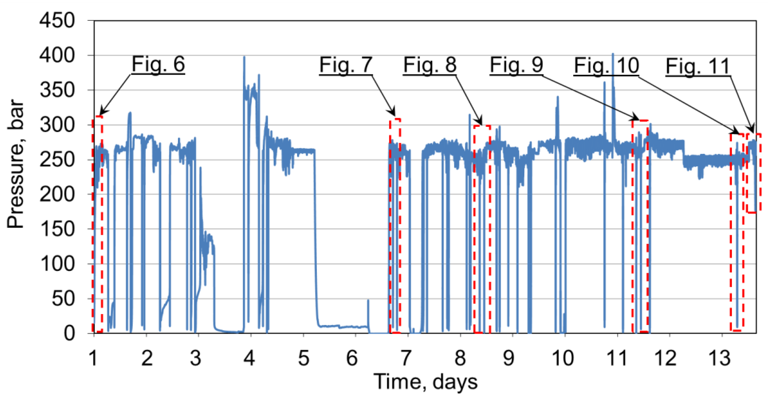
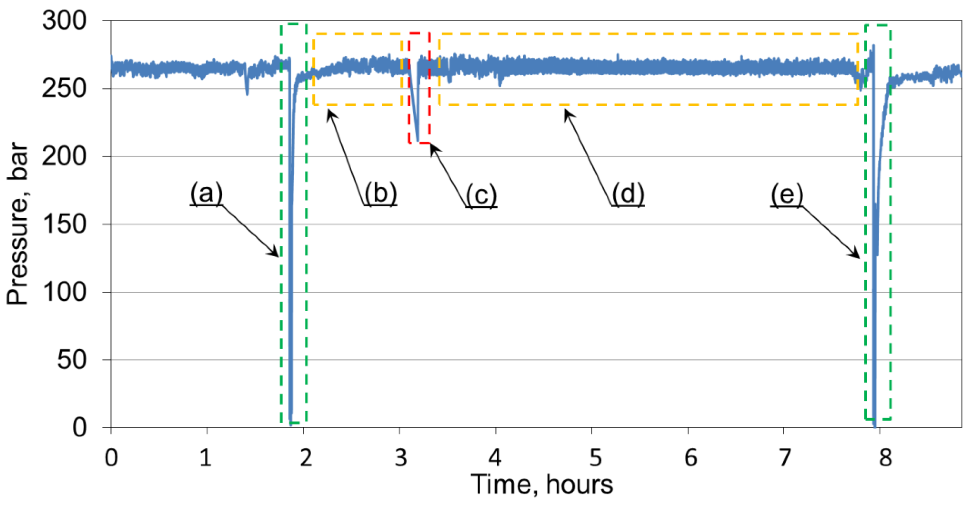
Figure 5 shows the measurement obtained from the actual conditions of the mining wall. This figure shows a section of measurements from about 12 research days. The average pressure under the piston of the hydraulic prop was up to 30 MPa, and was mainly related to the pressure of rock layers on the powered roof support. To fully illustrate the measurement for the operation of the hydraulic system with a double block,
Figure 5 has been divided into individually selected fragments of the operation of the double block with charging. The measurements presented in
Figure 5 were analyzed, consisting of the selection of several work areas of the block charging. The mining and geological conditions as well as the pressure of the layers of roof rocks were omitted. The focus was solely on the analysis of the pressure charging function.
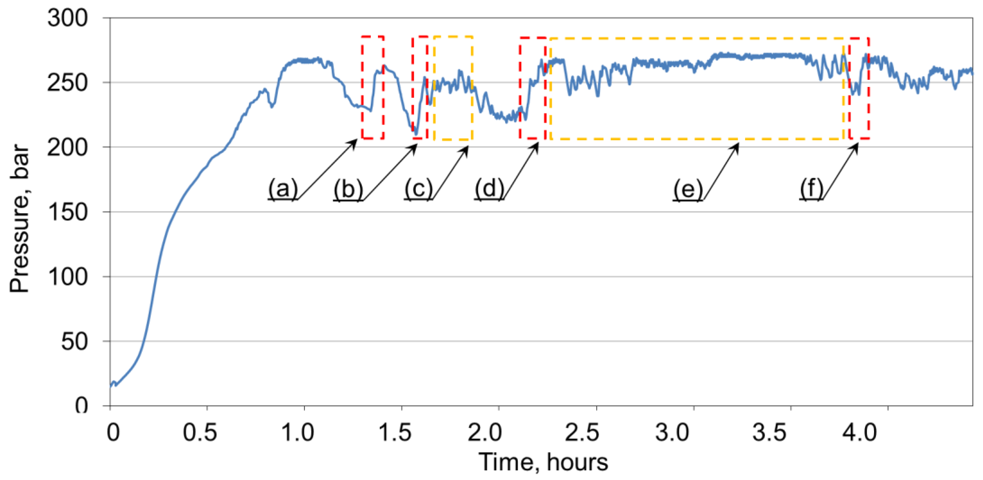
Figure 6 shows the analysis of the charging time, where four boosts of pressure were obtained. The first charge (a) was 1.9 min. The second charging started after 11.7 min and reached time (b), which was 2.4 min. For the subsequent charging (c), the maintenance time of the working load capacity of the powered roof support was 15.9 min. In the graph (
Figure 6), the third charging (d) reached a time of 5.0 min. The working load capacity between the third and fourth charging (e) was 95 min. However, the fourth charge in graph (f) was captured within 1.2 min.
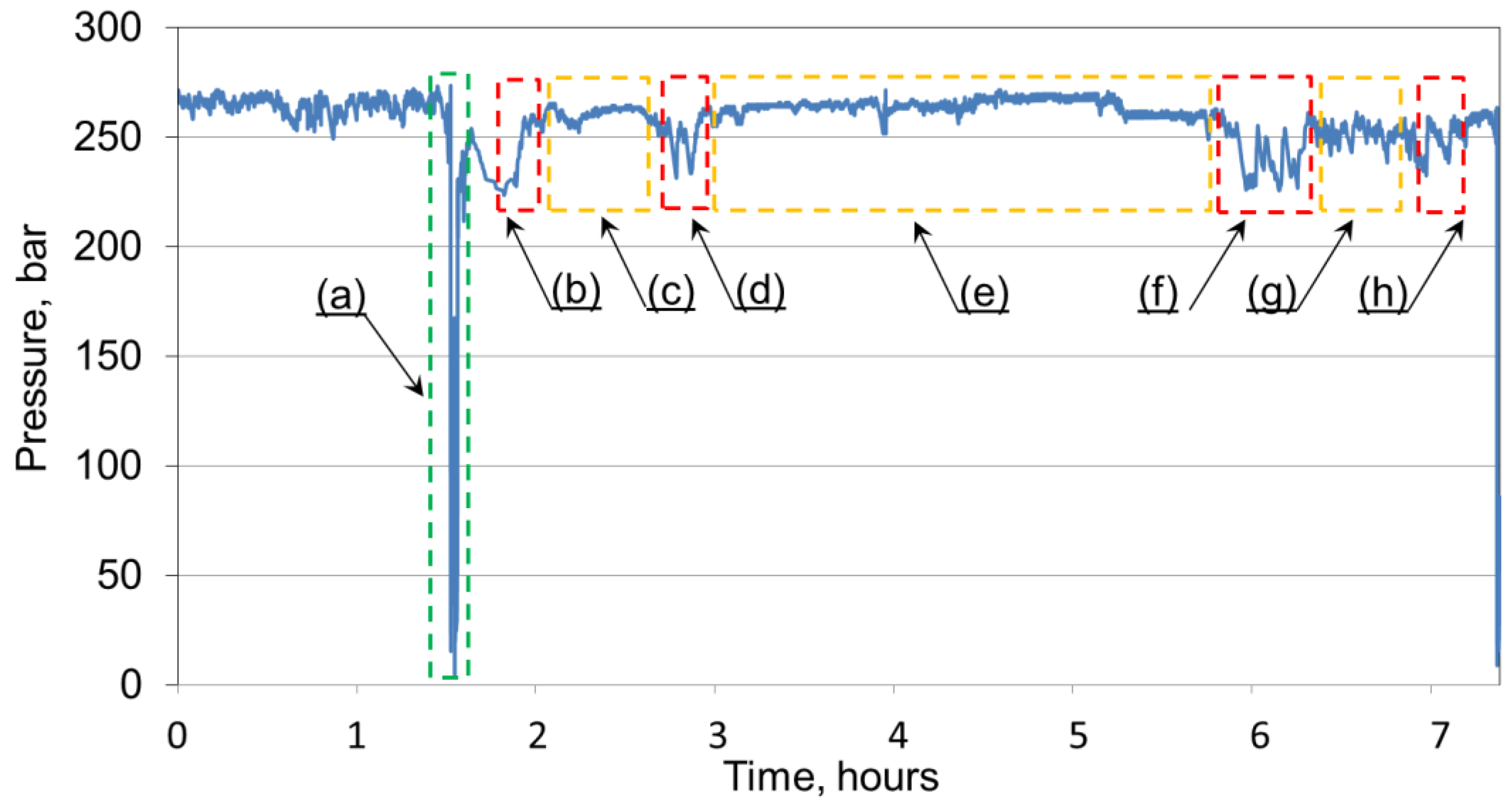
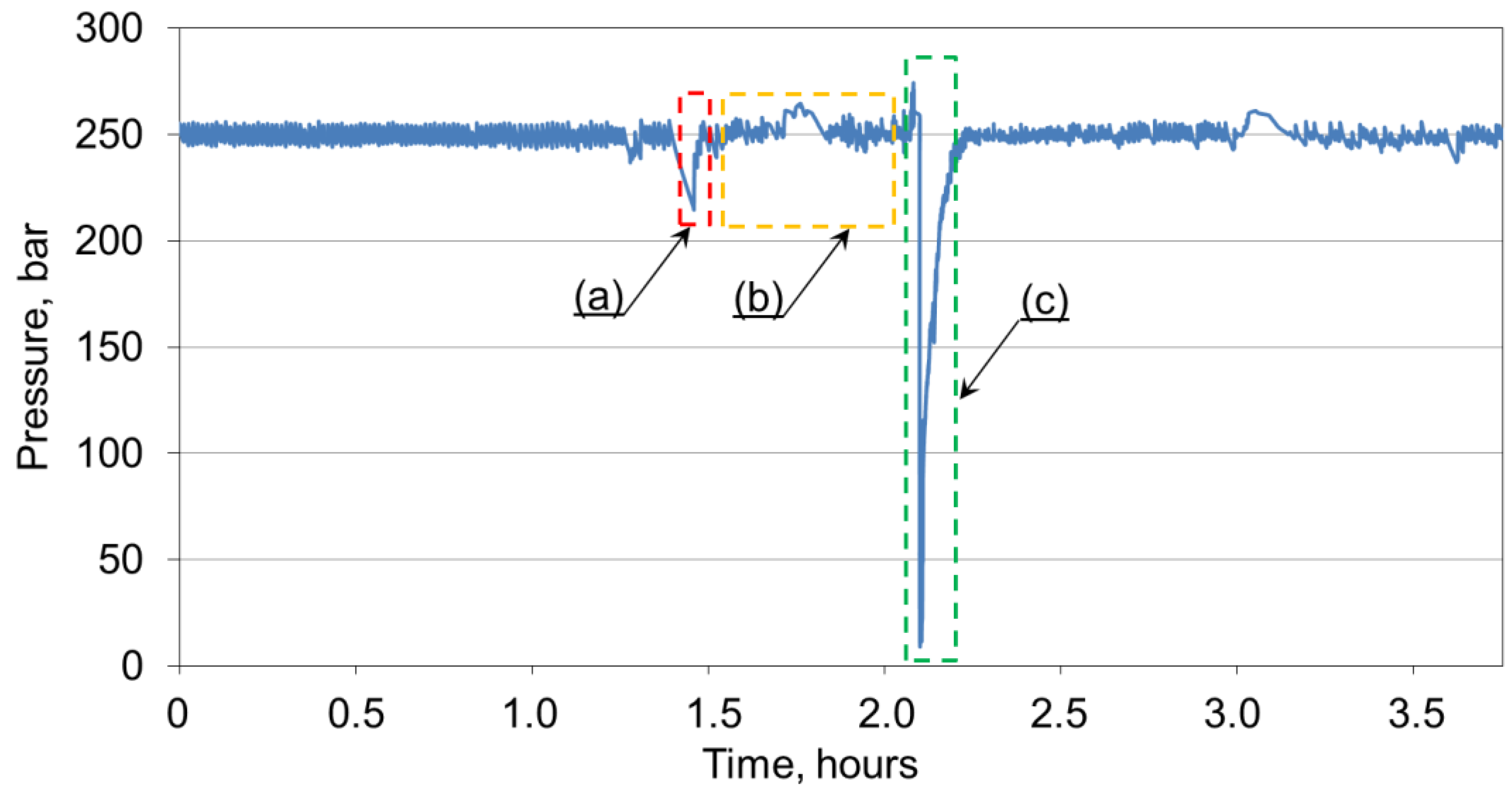
The graph in
Figure 7 considers the charging time together with the relocation of the section of the powered roof support. The powered roof-support section’s moving time was 6.9 min. The first charging (b) took 40 s, and the time load capacity of the powered roof support between the first and the second charging (c) was 48 min. The second charging time happened in (d) 2.6 min. The maintenance of the load capacity resulting from
Figure 7 before the subsequent charging (e) was within 180.9 min. The following charging time (f) was about 2.4 min. After this time, the working load capacity (g) lasted 40.6 min, after which, the subsequent charging occurred in a time (h) of 1.9 min.
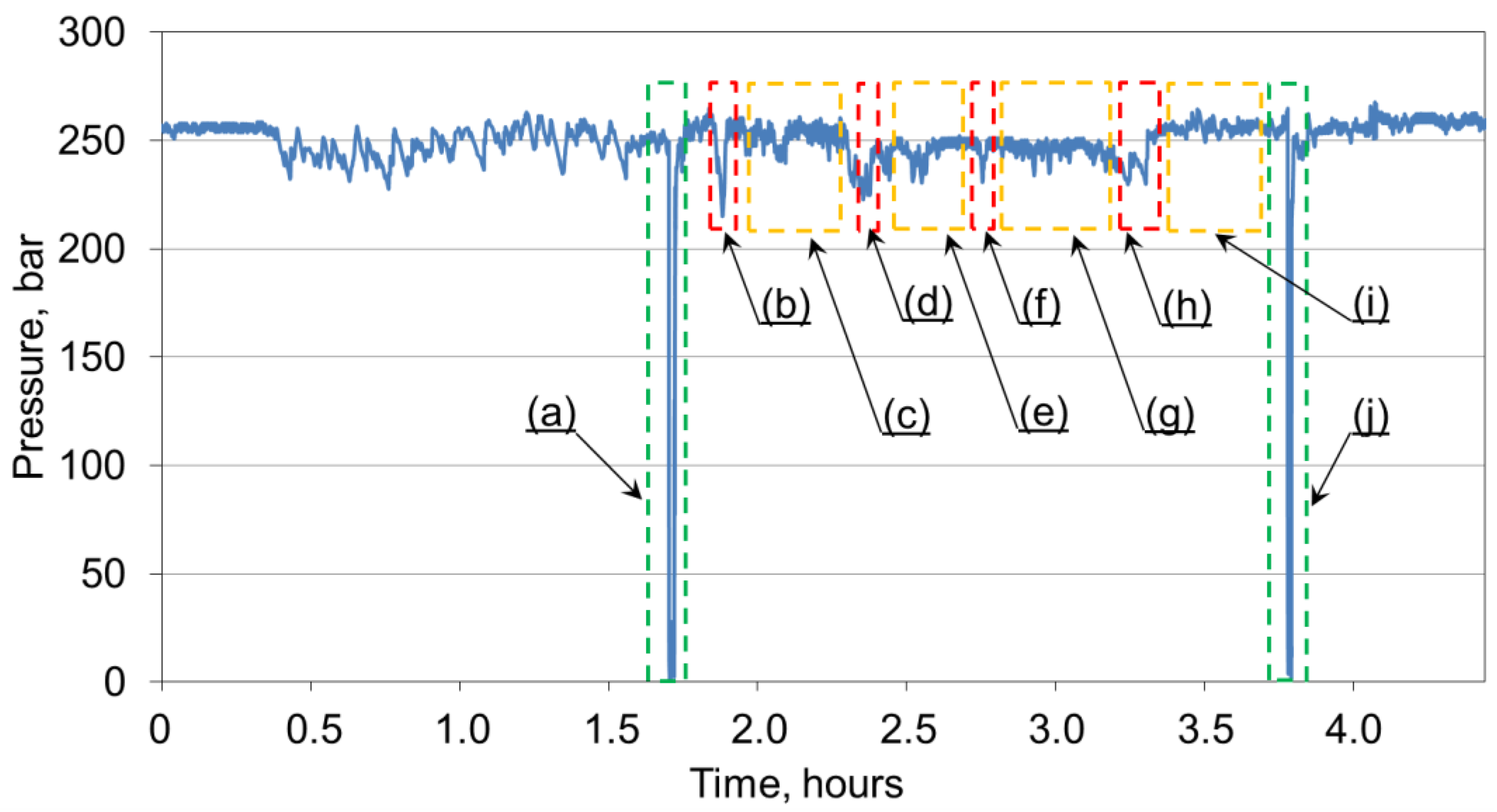
Figure 8 shows a graph of the obtained measurement for the charging function. The analysis considers the time of moving the section, which was (a) 2.2 min. After which, the first pressure charging time was recorded (b = 54 s). Maintaining the working load capacity (c) lasted about 24.4 min. On the other hand, its decrease caused a pressure charging which lasted about (d) 1.4 min. The working load capacity between the second and third charging was maintained within (e) 20.7 min. The third pressure boost was about (f) 50 s. On the other hand, the working load capacity was maintained for about (g) 23 min. The fourth charging took about (h) 22.5 s, after which, the working load capacity was maintained for the time of (i) 28.2 min. The analysis of the charging function was completed by moving the section to a new position, which took (j) 1.2 min.
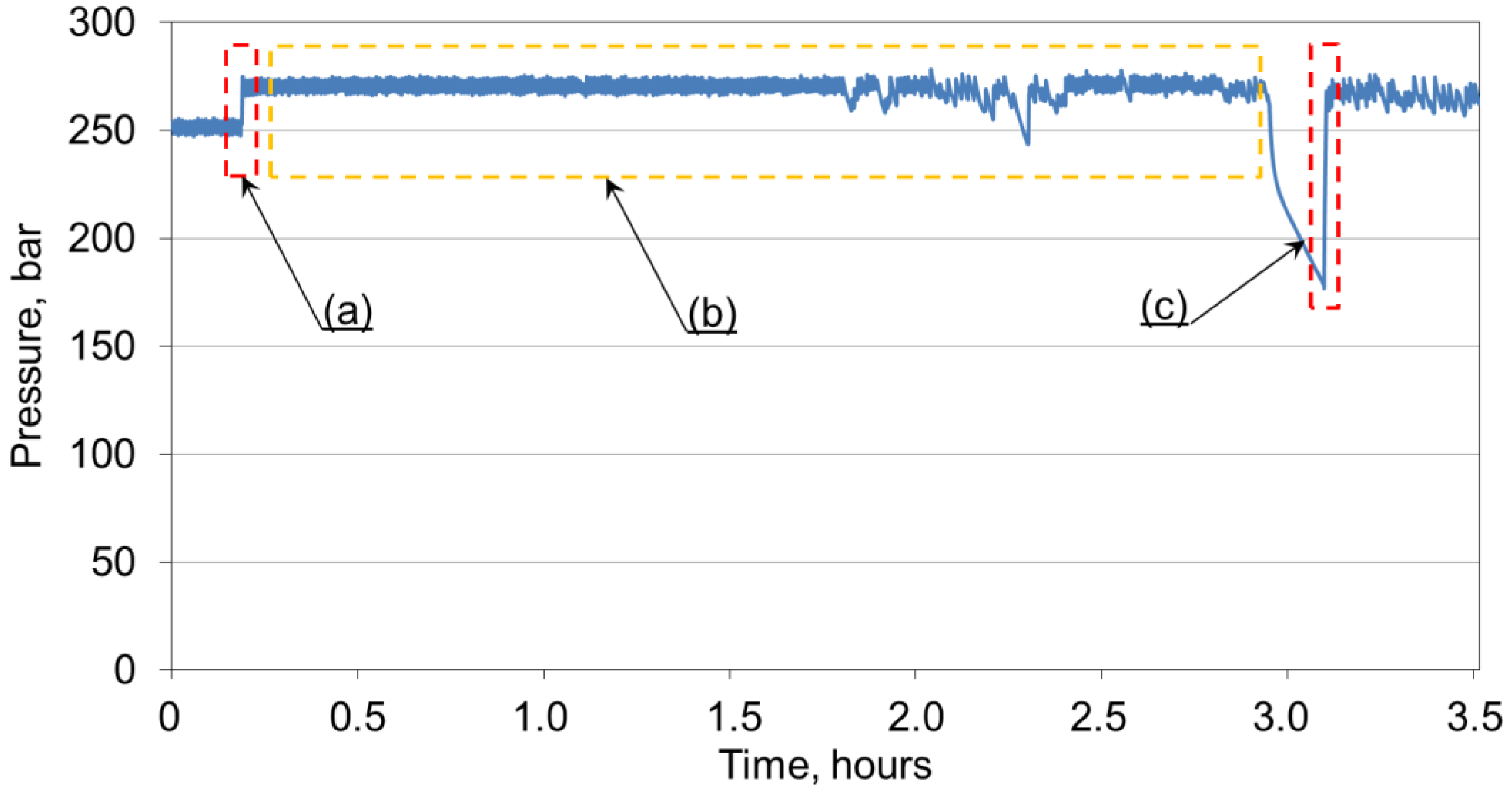
The graph in
Figure 9 shows the charging time (c), which was 13 s. However, the time of the first change of the powered roof-support section to the new position (a) was 3.2 min. Load capacity time between the first switching of the powered roof support (b) reached 72.9 min. The second movement of the section to a new location (e) happened in 8.6 min, and the load capacity time between this operation and the charging time (d) was 284.4 min.
Figure 10 shows the pressure charging time (a), which was about 1.2 min. On the other hand, the working load-capacity time (b) lasted about 37.3 min. Then, the section of the powered roof support was moved to a new place (c = 6.9 min). The measurement of the first charging time (
Figure 11) was about (a) 18.3 s. On the other hand, the maintenance of the load capacity before the second charging (b) was about 2.8 h. The research analysis in
Figure 11 ends with the time of the second charging (c) time, which was 23 s.
4. Discussion
The study considered pressure loss as an internal leak. It was formed on the inner seal, which caused a pressure drop in the prop. To obtain the best-possible operating parameters of the double block, we used a technically defective hydraulic prop employed in powered roof support in an extraction wall. The collected testing material presented in the graphs displayed in
Figure 5,
Figure 6,
Figure 7,
Figure 8,
Figure 9,
Figure 10 and
Figure 11 determined the actual charging time.
Table 3 shows the aggregated results of the charging time (T
D) results for the recorded pressure drops (∑∆p).
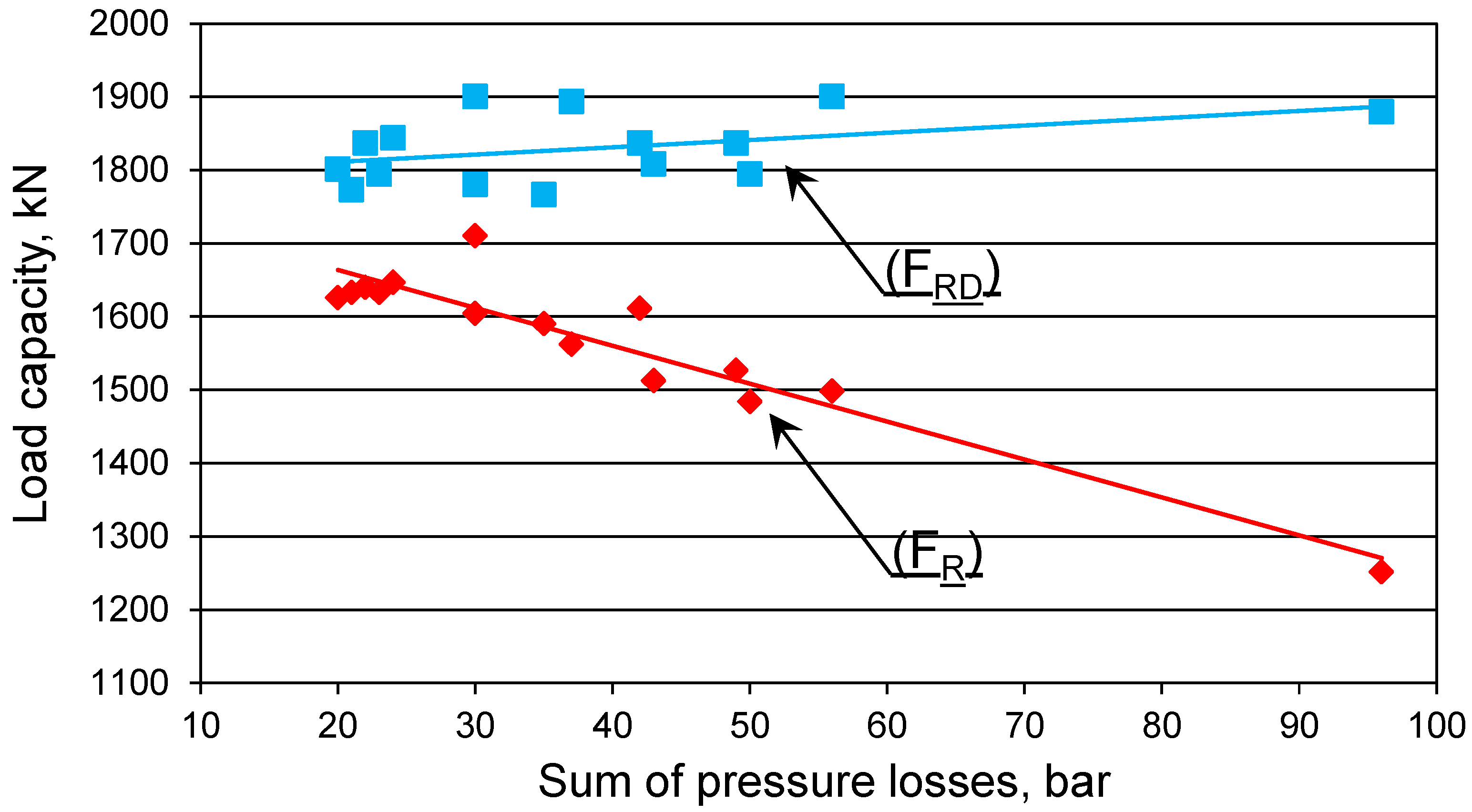
The pressure drops resulting from the internal leakage of the prop ranged from 20 to 96 bar. This directly affected the significant reduction of the actual load capacity of the prop. The charging time ranged from 13 to 298 s. Cases that recorded longer charging times were probably due to insufficient pressure in the main power line. The charging function was interrupted at pressures which were too low in the main power line. Only after the pressure in the main power line increased did the block continue to charge. This had a direct effect on the increase in the charging time.
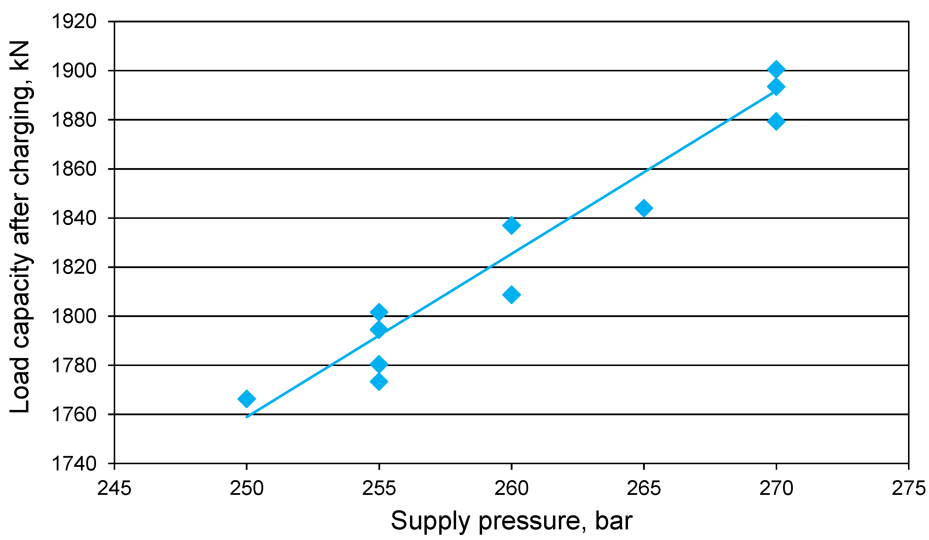
Based on Formula (1), the load capacity values for the tested prop were calculated. The temporary load capacity values were calculated for when the pressure drop occurred (F
R), and for after the pressure charging (F
RD). The results are recorded in
Table 3 and shown in
Figure 12 and
Figure 13. The research results suggest that a double block with a charging function ensured that the required working load capacity was maintained at a minimum level of 1766 kN. As a result of charging, the actual load capacity of the prop increased by about 10–20% in relation to the load capacity before charging. At higher pressure losses, the increase in load capacity after charging reached up to 50%. After charging, the prop’s load capacity was directly proportional to the temporary pressure in the main power line. The results of real tests confirmed the results obtained in bench tests [
65].
5. Conclusions
This work presents the implementation of the double-charging block in real condidions. The basis for the preparation for these tests were the previously conducted bench tests. Bench tests confirmed the correct operation of the double-charging block. Positive results of bench tests allowed to start testing in real conditions. The actual tests made it possible to determine the usefulness of the proposed solution in the event of an internal leak in the hydraulic prop of the powered roof support. Minimizing internal leaks is important to improving the reliability of powered roof support. This is important for improving safety in the longwall and maintaining the continuity of exploitation.
On the basis of the present research, it can be concluded that a double block with charging performs its function correctly in real conditions. The tests were carried out in a mining wall. For the research, a prop with an evolving internal leak was selected. As demonstrated by our measurements, after each pressure drop in the under-piston space of the prop, the block charged automatically. The charging time ranged from several seconds to several minutes. This time depended mainly on the instantaneous pressure value in the main power line.
This research proves the validity of the adopted theory. The solution minimizes the effects of internal leaks. Using a double block with charging ensured that the pressure in the under-piston space of the prop was maintained at a minimum of 250 bar. Thus, the prototype block maintained the required working load capacity in the prop, despite its internal leakage. It is essential to operate powered roof support and ensure safety adequately: the proposed solution allowed us to avoid costly and time-consuming prop replacement. Thus, using a block with charging may increase the efficiency of operation.
In connection with the test results, it is proposed that the powered roof support performs three functions. These functions already include two which are well-established, i.e., moving machines and devices using a control system as well as protecting against adverse mining and geological conditions. The third function proposed by the authors in this paper is eliminating any leaks that may affect the system’s adverse mining and geological conditions and the control functionality.
Author Contributions
Conceptualization, D.S. and B.B.; methodology, D.S. and B.B.; software, B.B.; validation, D.S., B.B. and S.Z.; formal analysis, A.J.S.S.; investigation, D.S.; resources, R.D.; data curation, S.Z.; writing—original draft preparation, D.S., B.B. and A.J.S.S.; writing—review and editing, D.S. and B.B.; visualization, D.S.; supervision, D.S.; project administration, D.S., B.B. and S.Z.; funding acquisition, D.S. and S.Z. All authors have read and agreed to the published version of the manuscript.
Funding
This research received no external funding.
Institutional Review Board Statement
The study was conducted according to the guidelines of the Declaration of Helsinki and approved by the Mining Institute Review Board of T.F. Gorbachev Kuzbass State Technical University (Protocol Number 1101 from 29 November 2021).
Informed Consent Statement
Not applicable.
Data Availability Statement
Not applicable.
Conflicts of Interest
The authors declare no conflict of interest.
References
- Bazaluk, O.; Slabyi, O.; Vekeryk, V.; Velychkovych, A.; Ropyak, L.; Lozynskyi, V. A Technology of Hydrocarbon Fluid Production Intensification by Productive Stratum Drainage Zone Reaming. Energies 2021, 14, 3514. [Google Scholar] [CrossRef]
- Patyk, M.; Bodziony, P.; Krysa, Z. A Multiple Criteria Decision Making Method to Weight the Sustainability Criteria of Equipment Selection for Surface Mining. Energies 2021, 14, 3066. [Google Scholar] [CrossRef]
- Kumar, R.; Singh, A.K.; Mishra, A.K.; Singh, R. Underground mining of thick coal seams. Int. J. Min. Sci. Tech. 2015, 25, 885–896. [Google Scholar] [CrossRef]
- Gil, J.; Kołodziej, M.; Szurgacz, D.; Stoiński, K. Introduction of standardization of powered roof supports to increase production efficiency of Polska Grupa Górnicza, S.A. Min. Inform. Autom. Electr. Eng. 2019, 56, 33–38. [Google Scholar] [CrossRef]
- Pokorny, J.; Dlouhá, D.; Kucera, P. Study of the necessity of use virtual origin in assessment of selected fire plume characteristics. MM Sci. J. 2016, 5, 1424–1428. [Google Scholar] [CrossRef]
- Pokorny, J.; Mozer, V.; Malerova, L.; Dlouhá, D.; Wilkinson, P. A simplified method for establishing safe available evacuation time based on a descending smoke layer. Commun. Sci. Lett. Univ. Zilina 2018, 20, 28–34. [Google Scholar] [CrossRef]
- Uth, F.; Polnik, B.; Kurpiel, W.; Baltes, R.; Kriegsch, P.; Clause, E. An innovate person detection system based on thermal imaging cameras dedicate for underground belt conveyors. Min. Sci. 2019, 26, 263–276. [Google Scholar] [CrossRef]
- Szurgacz, D.; Zhironkin, S.; Pokorný, J.; Spearing, A.J.S.; Vöth, S.; Cehlár, M.; Kowalewska, I. Development of an Active Training Method for Belt Conveyor. Int. J. Environ. Res. Public Health 2022, 19, 437. [Google Scholar] [CrossRef]
- Bazaluk, O.; Velychkovych, A.; Ropyak, L.; Pashechko, M.; Pryhorovska, T.; Lozynskyi, V. Influence of Heavy Weight Drill Pipe Material and Drill Bit Manufacturing Errors on Stress State of Steel Blades. Energies 2021, 14, 4198. [Google Scholar] [CrossRef]
- Góralczyk, M.; Krot, P.; Zimroz, R.; Ogonowski, S. Increasing Energy Efficiency and Productivity of the Comminution Process in Tumbling Mills by Indirect Measurements of Internal Dynamics—An Overview. Energies 2020, 13, 6735. [Google Scholar] [CrossRef]
- Doroszuk, B.; Król, R. Conveyor belt wear caused by material acceleration in transfer stations. Min. Sci. 2019, 26, 189–201. [Google Scholar] [CrossRef]
- Grzesiek, A.; Zimroz, R.; Śliwiński, P.; Gomolla, N.; Wyłomańska, A. A Method for Structure Breaking Point Detection in Engine Oil Pressure Data. Energies 2021, 14, 5496. [Google Scholar] [CrossRef]
- Buyalich, G.; Buyalich, K.; Byakov, M. Factors Determining the Size of Sealing Clearance in Hydraulic Legs of Powered Supports. E3S Web Conf. 2017, 21, 3018. [Google Scholar] [CrossRef]
- Bortnowski, P.; Gładysiewicz, L.; Król, R.; Ozdoba, M. Energy Efficiency Analysis of Copper Ore Ball Mill Drive Systems. Energies 2021, 14, 1786. [Google Scholar] [CrossRef]
- Borkowski, P.J. Comminution of Copper Ores with the Use of a High-Pressure Water Jet. Energies 2020, 13, 6274. [Google Scholar] [CrossRef]
- Kawalec, W.; Suchorab, N.; Konieczna-Fuławka, M.; Król, R. Specific energy consumption of a belt conveyor system in a continuous surface mine. Energies 2020, 13, 5214. [Google Scholar] [CrossRef]
- Wodecki, J.; Góralczyk, M.; Krot, P.; Ziętek, B.; Szrek, J.; Worsa-Kozak, M.; Zimroz, R.; Śliwiński, P.; Czajkowski, A. Process Monitoring in Heavy Duty Drilling Rigs—Data Acquisition System and Cycle Identification Algorithms. Energies 2020, 13, 6748. [Google Scholar] [CrossRef]
- Szurgacz, D.; Zhironkin, S.; Vöth, S.; Pokorný, J.; Spearing, A.J.S.; Cehlár, M.; Stempniak, M.; Sobik, L. Thermal Imaging Study to Determine the Operational Condition of a Conveyor Belt Drive System Structure. Energies 2021, 14, 3258. [Google Scholar] [CrossRef]
- Kawalec, W.; Błażej, R.; Konieczna, M.; Król, R. Laboratory Tests on e-pellets effectiveness for ore tracking. Min. Sci. 2018, 25, 7–18. [Google Scholar] [CrossRef]
- Zimroz, P.; Trybała, P.; Wróblewski, A.; Góralczyk, M.; Szrek, J.; Wójcik, A.; Zimroz, R. Application of UAV in Search and Rescue Actions in Underground Mine—A Specific Sound Detection in Noisy Acoustic Signal. Energies 2021, 14, 3725. [Google Scholar] [CrossRef]
- Bardzinski, P.; Jurdziak, L.; Kawalec, W.; Król, R. Copper ore quality tracking in a belt conveyor system using simulation tools. Nat. Resour. Res. 2020, 29, 1031–1040. [Google Scholar] [CrossRef]
- Wang, J.; Wang, Z. Systematic principles of surrounding rock control in longwall mining within thick coal seams. Int. J. Min. Sci. Tech. 2019, 29, 591–598. [Google Scholar] [CrossRef]
- Jixiong, Z.; Spearing, A.J.S.; Xiexing, M.; Shuai, G.; Qiang, S. Green coal mining technique integrating mining-dressing-gas draining-backfilling-mining. Int. J. Min. Sci. Tech. 2017, 27, 17–27. [Google Scholar]
- Krauze, K.; Mucha, K.; Wydro, T.; Pieczora, E. Functional and Operational Requirements to Be Fulfilled by Conical Picks Regarding Their Wear Rate and Investment Costs. Energies 2021, 14, 3696. [Google Scholar] [CrossRef]
- Kotwica, K.; Stopka, G.; Kalita, M.; Bałaga, D.; Siegmund, M. Impact of Geometry of Toothed Segments of the Innovative KOMTRACK Longwall Shearer Haulage System on Load and Slip during the Travel of a Track Wheel. Energies 2021, 14, 2720. [Google Scholar] [CrossRef]
- Ji, Y.; Zhang, Y.; Huang, Z.; Shao, Z.; Gao, Y. Theoretical analysis of support stability in large dip angle coal seam mined with fully-mechanized top coal caving. Min. Sci. 2020, 27, 73–87. [Google Scholar]
- Xiaozhen, W.; Jialin, X.; Weibing, Z.; Yingchun, L. Roof pre-blasting to prevent support crushing and water inrush accidents. Int. J. Min. Sci. Tech. 2012, 22, 379–384. [Google Scholar]
- Klishin, V.I.; Klishin, S.V. Coal Extraction from Thick Flat and Steep Beds. J. Min. Sci. 2010, 46, 149–159. [Google Scholar] [CrossRef]
- Mo, S.; Tutuk, K.; Saydam, S. Management of floor heave at Bulga Underground Operations—A case study. Int. J. Min. Sci. Tech. 2019, 29, 73–78. [Google Scholar] [CrossRef]
- Frith, R.C. A holistic examination of the load rating design of longwall shields after more than half a century of mechanised longwall mining. Int. J. Min. Sci. Tech. 2015, 26, 199–208. [Google Scholar] [CrossRef]
- Król, R.; Kisielewski, W. Research of loading carrying idlers used in belt conveyor-practical applications. Diagnostyka 2014, 15, 67–74. [Google Scholar]
- Ziętek, B.; Banasiewicz, A.; Zimroz, R.; Szrek, J.; Gola, S. A Portable Environmental Data-Monitoring System for Air Hazard Evaluation in Deep Underground Mines. Energies 2020, 13, 6331. [Google Scholar] [CrossRef]
- Ji, Y.; Ren, T.; Wynne, P.; Wan, Z.; Zhaoyang, M.; Wang, Z. A comparative study of dust control practices in Chinese and Australian longwall coal mines. Int. J. Min. Sci. Tech. 2016, 25, 687–706. [Google Scholar] [CrossRef]
- Prostański, D. Empirical Models of Zones Protecting Against Coal Dust Explosion. Arch. of Min. Sci. 2017, 62, 611–619. [Google Scholar] [CrossRef]
- Bajda, M.; Hardygóra, M. Analysis of Reasons for Reduced Strength of Multiply Conveyor Belt Splices. Energies 2021, 14, 1512. [Google Scholar] [CrossRef]
- Woźniak, D.; Hardygóra, M. Method for laboratory testing rubber penetration of steel cords in conveyor belts. Min. Sci. 2020, 27, 105–117. [Google Scholar] [CrossRef]
- Bajda, M.; Błażej, R.; Hardygóra, M. Optimizing splice geometry in multiply conveyor belts with respect to stress in adhesive bonds. Min. Sci. 2018, 25, 195–206. [Google Scholar] [CrossRef]
- Adach-Pawelus, K.; Pawelus, D. Influence of Driving Direction on the Stability of a Group of Headings Located in a Field of High Horizontal Stresses in the Polish Underground Copper Mines. Energies 2021, 14, 5955. [Google Scholar] [CrossRef]
- Gładysiewicz, L.; Król, R.; Kisielewski, W.; Kaszuba, D. Experimental determination of belt conveyors artificial friction coefficient. Acta Montan. Slovaca 2017, 22, 206–214. [Google Scholar]
- Huang, P.; Spearing, S.; Ju, F.; Jessu, K.V.; Wang, Z.; Ning, P. Control Effects of Five Common Solid Waste Backfilling Materials on In Situ Strata of Gob. Energies 2019, 12, 154. [Google Scholar] [CrossRef]
- Wajs, J.; Trybała, P.; Górniak-Zimroz, J.; Krupa-Kurzynowska, J.; Kasza, D. Modern Solution for Fast and Accurate Inventorization of Open-Pit Mines by the Active Remote Sensing Technique—Case Study of Mikoszów Granite Mine (Lower Silesia, SW Poland). Energies 2021, 14, 6853. [Google Scholar] [CrossRef]
- Rajwa, S.; Tomasz Janoszek, T.; Stanisław Prusek, S. Influence of canopy ratio of powered roof support on longwall working stability—A case study. Int. J. Min. Sci. Tech. 2019, 29, 591–598. [Google Scholar] [CrossRef]
- Rajwa, S.; Janoszek, T.; Prusek, S. Model tests of the effect of active roof support on the working stability of a longwall. Comput. Geotech. 2020, 118, 103302. [Google Scholar] [CrossRef]
- Juganda, A.; Strebinger, C.; Brune, J.F.; Bogin, G.E. Discrete modeling of a longwall coal mine gob for CFD simulation. Int. J. Min. Sci. Tech. 2020, 30, 463–469. [Google Scholar] [CrossRef]
- Janus, J.; Krawczyk, J. Measurement and Simulation of Flow in a Section of a Mine Gallery. Energies 2021, 14, 4894. [Google Scholar] [CrossRef]
- Świątek, J.; Janoszek, T.; Cichy, T.; Stoiński, K. Computational Fluid Dynamics Simulations for Investigation of the Damage Causes in Safety Elements of Powered Roof Supports—A Case Study. Energies 2021, 14, 1027. [Google Scholar] [CrossRef]
- Dlouhá, D.; Pokorný, J.; Dlouhá, K. Necessity of knowledge about math in safety engineering. In Proceedings of the 14th Conference E-Learning: Unlocking the Gate to Education around the Globe, Prague, Czech Republic, 20–21 June 2019; pp. 380–386. [Google Scholar]
- Baiul, K.; Khudyakov, A.; Vashchenko, S.; Krot, P.V.; Solodka, N. The experimental study of compaction parameters and elastic after-effect of fine fraction raw materials. Min. Sci. 2020, 27, 7–18. [Google Scholar] [CrossRef]
- Dlouhá, D.; Dubovský, V. The improvement of the lake Most evaporation estimates. Inż. Miner. 2019, 21, 159–164. [Google Scholar]
- Dlouhá, D.; Dubovský, V.; Pospíšil, L. Optimal calibration of evaporation models against Penman-Monteith Equatíon. Water 2021, 13, 1484. [Google Scholar] [CrossRef]
- Dubovský, V.; Dlouhá, D.; Pospíšil, L. The calibration of evaporation models against the Penman-Monteith equation on lake Most. Sustainability 2021, 13, 313. [Google Scholar] [CrossRef]
- Dlouhá, D.; Hamříková, R. Interactive distance materials of mathematics for VŠB-TU Ostrava. In Proceedings of the 13th Conference Overcoming the Challenges and the Barriers in Open Education, Prague, Czech Republic, 25–26 June 2018; pp. 67–72. Available online: https://www.fast.vsb.cz/230/cs/Veda-a-vyzkum/Publikace/2018/ (accessed on 1 November 2021).
- Dlouhá, D.; Kozlová, K. Knowledge assessment of student’s high school mathematics. In Proceedings of the 17th Conference on Applied Mathematics (APLIMAT 2019), Bratislava, Slovak Republic, 5–7 February 2019; Volume 1, pp. 243–252. [Google Scholar]
- Hamříková, R.; Dlouhá, D. Video tutorials for students of the master’s program. In Proceedings of the 12th Conference Open Education as a Way to a Knowledge Society, Prague, Czech Republic, 26–27 June 2017; pp. 446–451. [Google Scholar]
- Dlouhá, D.; Hamříková, R. Our experience with the involvement of students in the creation of study materials. In Proceedings of the 17th Conference on Applied Mathematics (APLIMAT 2019), Bratislava, Slovak Republic, 5–7 February 2019; Volume 1, pp. 301–308. [Google Scholar]
- Peng, S.S.; Feng, D.; Cheng, J.; Yang, L. Automation in U.S. longwall coal mining: A state-of-the-art review. Int. J. Min. Sci. Tech. 2019, 29, 151–159. [Google Scholar] [CrossRef]
- Ralston, J.C.; Hargrave, C.O.; Dunn, M.T. Longwall automation: Trends, challenges and opportunities. Int. J. Min. Sci. Tech. 2017, 27, 733–739. [Google Scholar] [CrossRef]
- Ralston, J.C.; Reid, D.C.; Dunn, M.T.; Hainsworth, D.W. Longwall automation: Delivering enabling technology to achieve safer and more productive underground mining. Int. J. Min. Sci. Tech. 2015, 25, 865–876. [Google Scholar] [CrossRef]
- Hu, S.; Ma, L.; Guo, J.; Yang, P. Support-surrounding rock relationship and top-coal movement laws in large dip angle fully-mechanized caving face. Int. J. Min. Sci. Tech. 2018, 28, 533–539. [Google Scholar]
- Buyalich, G.; Byakov, M.; Buyalich, K. Factors Determining Operation of Lip Seal in the Sealed Gap of the Hydraulic Props of Powered Supports. E3S Web Conf. 2017, 41, 1045. [Google Scholar] [CrossRef]
- Szurgacz, D.; Zhironkin, S.; Cehlár, M.; Vöth, S.; Spearing, S.; Liqiang, M. A Step-by-Step Procedure for Tests and Assessment of the Automatic Operation of a Powered Roof Support. Energies 2021, 14, 697. [Google Scholar] [CrossRef]
- Buyalich, G.; Byakov, M.; Buyalich, K.; Shtenin, E. Development of Powered Support Hydraulic Legs with Improved Performance. E3S Web Conf. 2019, 105, 3025. [Google Scholar] [CrossRef]
- Szurgacz, D. Dynamic Analysis for the Hydraulic Leg Power of a Powered Roof Support. Energies 2021, 14, 5715. [Google Scholar] [CrossRef]
- Stoiński, K.; Mika, M. Dynamics of Hydraulic Leg of Powered Longwall Support. J. Min. Sci. 2003, 39, 72–77. [Google Scholar] [CrossRef]
- Szurgacz, D.; Borska, B.; Zhironkin, S.; Diederichs, R.; Spearing, A.J.S. Optimization of the Load Capacity System of Powered Roof Support: A Review. Energies 2022, 15, 6061. [Google Scholar] [CrossRef]
- Irresberger, H.; Grawe, F.; Migenda, P. Zmechanizowane Obudowy Ścianowe (Podręcznik dla Praktyków); Wyd. Tiefenbach Polska Sp. z o.o.: Piekary Śląskie, Poland, 2003. [Google Scholar]
Figure 1.
Work cycle for the powered roof-support section, where 1—withdrawing the powered roof-support section, 2—moving the powered roof-support section to a new location, 3—spragging the powered roof-support section, 4—longwall scraper conveyor, 5—roof, 6—coal, 7—floor, 8—goafs.
Figure 1.
Work cycle for the powered roof-support section, where 1—withdrawing the powered roof-support section, 2—moving the powered roof-support section to a new location, 3—spragging the powered roof-support section, 4—longwall scraper conveyor, 5—roof, 6—coal, 7—floor, 8—goafs.
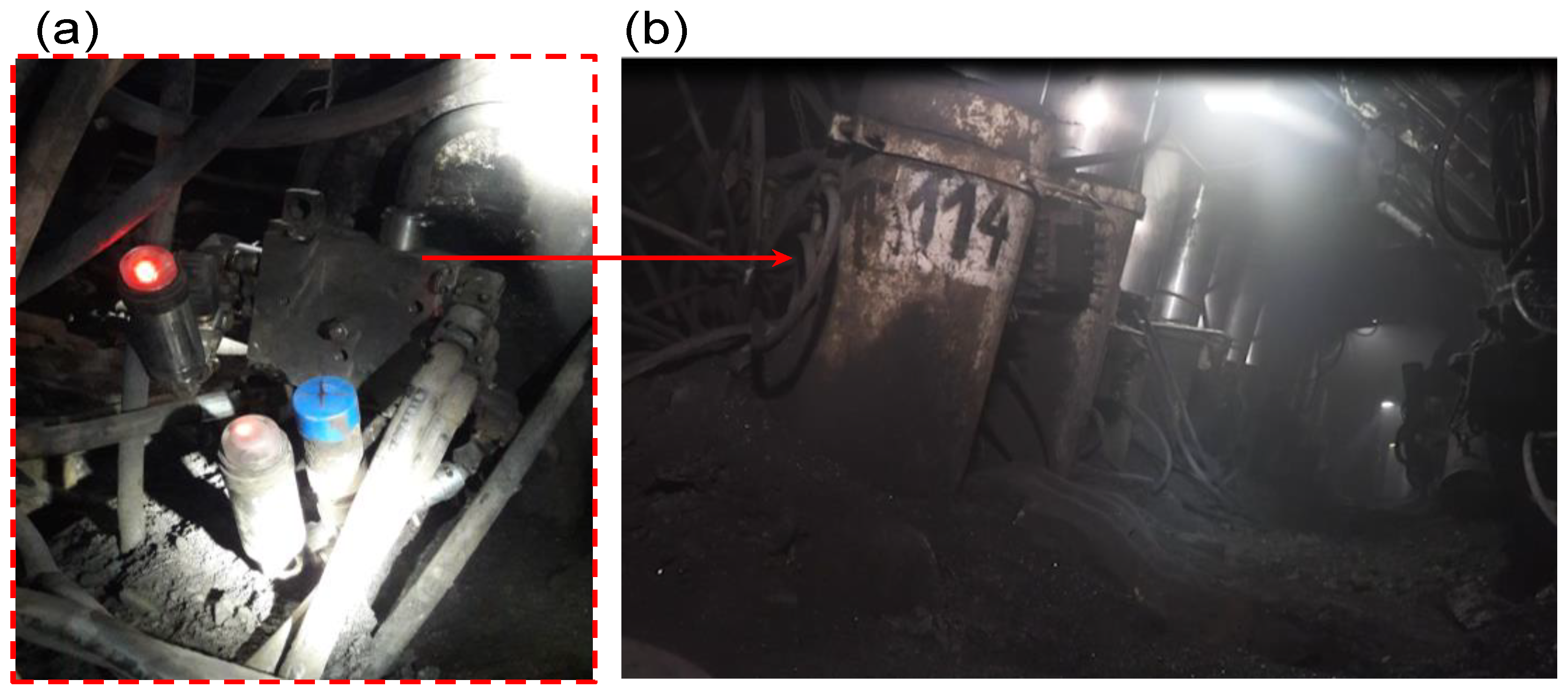
Figure 2.
The extraction wall in which the research was carried out, where: (a) the measurement system with a prototype double block was installed on a prop; (b) view of the section on which the research was carried out.
Figure 2.
The extraction wall in which the research was carried out, where: (a) the measurement system with a prototype double block was installed on a prop; (b) view of the section on which the research was carried out.
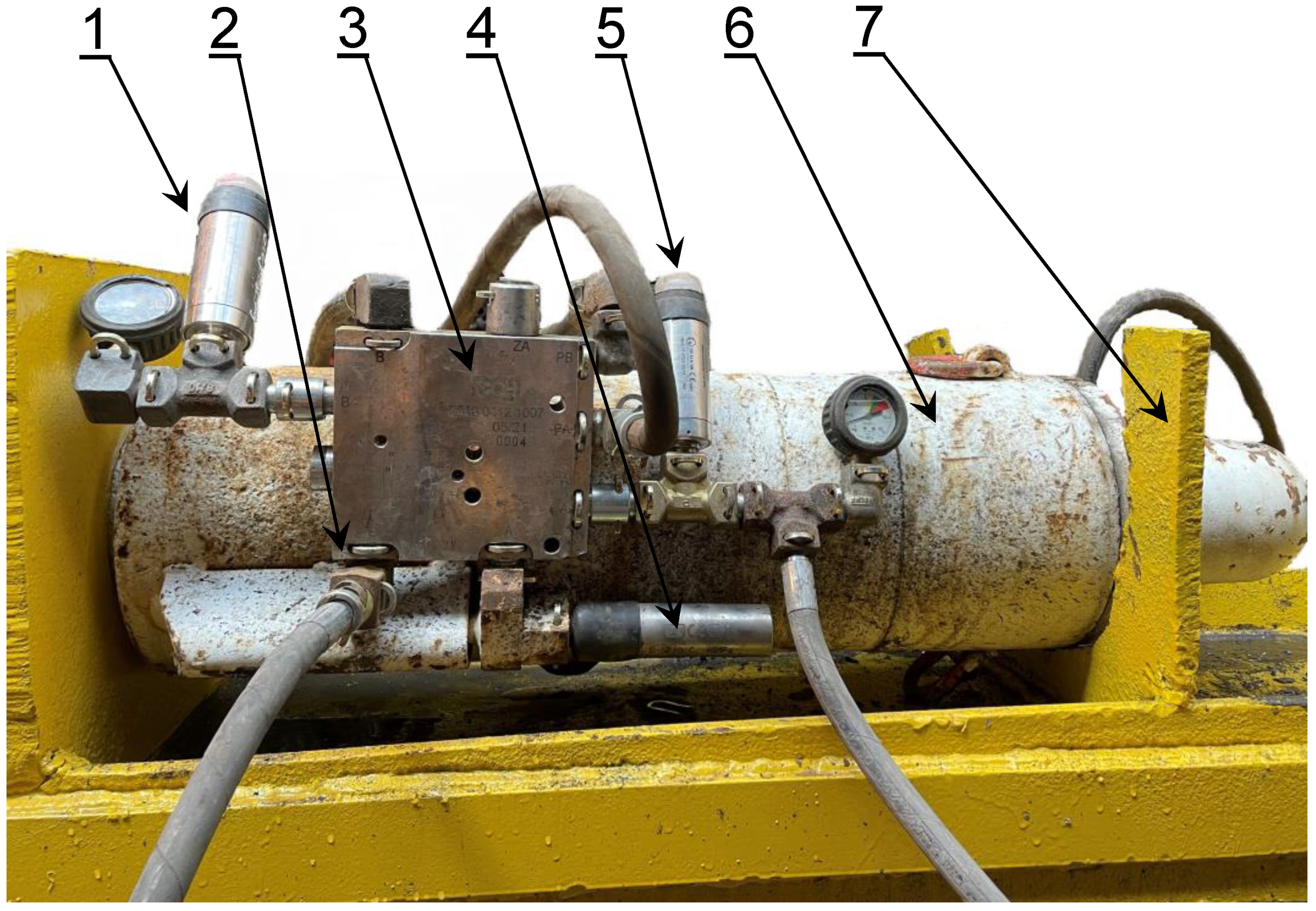
Figure 3.
View of the test bench for verification of the double block charging function, where: 1—pressure sensor for the supra-block space, 2—pressure charging, 3—double block with pressure charging, 4—safety valve, 5—pressure sensor for the sub-block space, 6—hydraulic prop, 7—frame of test site.
Figure 3.
View of the test bench for verification of the double block charging function, where: 1—pressure sensor for the supra-block space, 2—pressure charging, 3—double block with pressure charging, 4—safety valve, 5—pressure sensor for the sub-block space, 6—hydraulic prop, 7—frame of test site.
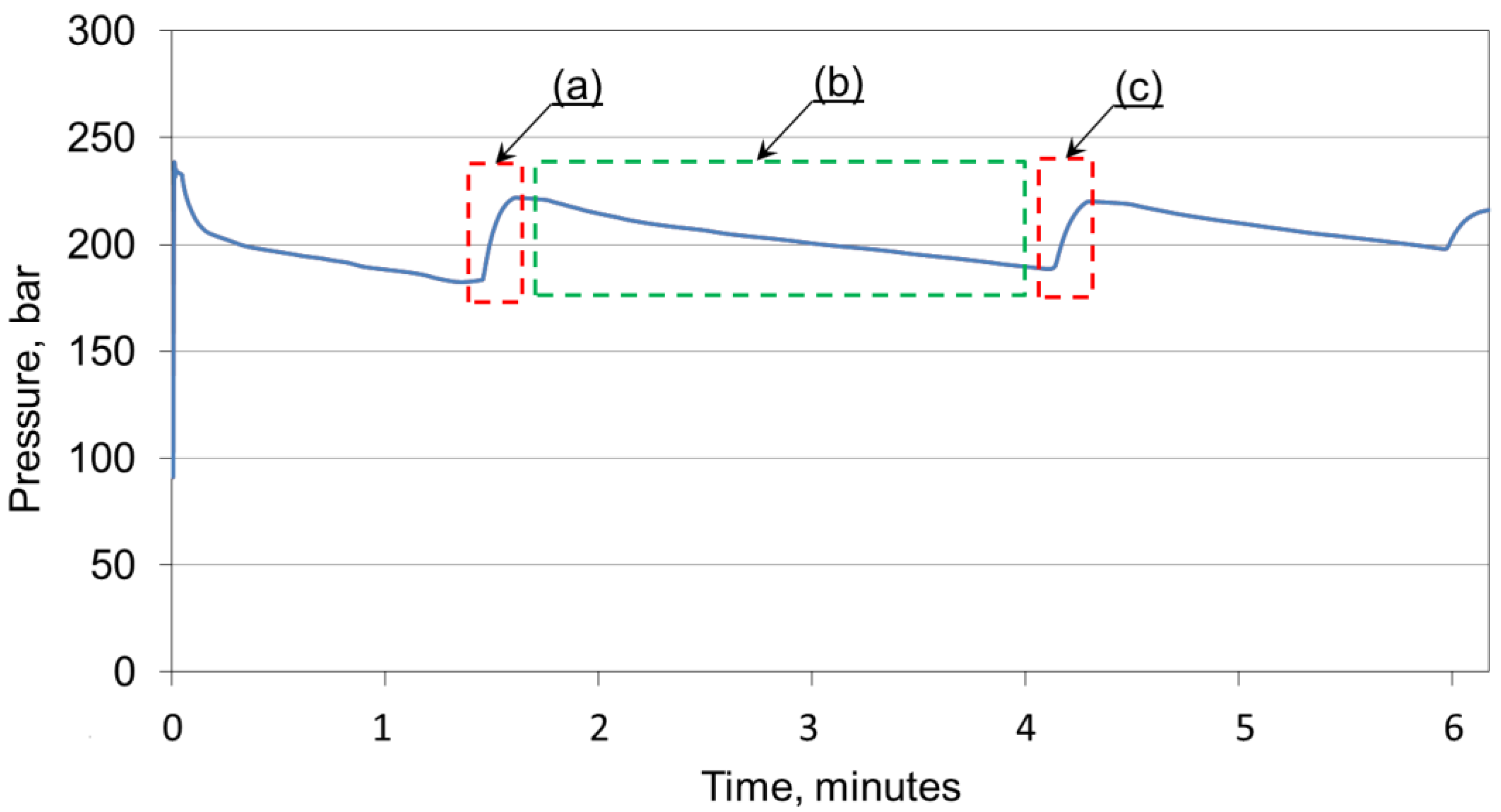
Figure 4.
Stationary test of the double block charging function, where: (a) the charging time is 15.1 s; (b) the time of loss of the prop’s load capacity is 141.8 s; (c) the charging time is 9.6 s.
Figure 4.
Stationary test of the double block charging function, where: (a) the charging time is 15.1 s; (b) the time of loss of the prop’s load capacity is 141.8 s; (c) the charging time is 9.6 s.
Figure 5.
Testing the functionality of a double block in real conditions.
Figure 5.
Testing the functionality of a double block in real conditions.
Figure 6.
The four times ranges of pressure charging obtained to maintain the required working load capacity.
Figure 6.
The four times ranges of pressure charging obtained to maintain the required working load capacity.
Figure 7.
Analysis of the charging function in real conditions.
Figure 7.
Analysis of the charging function in real conditions.
Figure 8.
Analysis of the pressure charging function with the time of moving the section to a new position.
Figure 8.
Analysis of the pressure charging function with the time of moving the section to a new position.
Figure 9.
Analysis of the charging function during the tests.
Figure 9.
Analysis of the charging function during the tests.
Figure 10.
Testing the charging function along with the section relocation.
Figure 10.
Testing the charging function along with the section relocation.
Figure 11.
Analysis of the actual load capacity, including the charging function.
Figure 11.
Analysis of the actual load capacity, including the charging function.
Figure 12.
Analysis of the prop’s actual load capacity before charging FR and after charging FRD.
Figure 12.
Analysis of the prop’s actual load capacity before charging FR and after charging FRD.
Figure 13.
Analysis of the prop’s actual load capacity after charging depending on the pressure in the main power line.
Figure 13.
Analysis of the prop’s actual load capacity after charging depending on the pressure in the main power line.
Table 1.
Technical characteristics of the hydraulic prop of the powered roof support.
Table 1.
Technical characteristics of the hydraulic prop of the powered roof support.
| Operation Range | Work Unit |
|---|
| Working diameter | 300 mm/230 mm |
| Supply pressure | 25 ÷ 32 MPa |
| Nominal pressure | 43 MPa |
| Initial load capacity | 1767 ÷ 2262 kN |
| Working load capacity | 3039 kN |
| Hydraulic I stage stroke | 1212 mm |
| Hydraulic II stage stroke | 1129 mm |
| Min. length | 1897 mm |
| Max. length | 4238 mm |
Table 2.
Technical characteristics of the prototype double block.
Table 2.
Technical characteristics of the prototype double block.
| Operation Range | Work Unit |
|---|
| Nominal pressure | 480 bar |
| Flow diameter | Ø 10 mm |
| Maximum flow | 400 l/min |
| Number of check valve cartridges | 3 |
| Work temperature | 40 °C ÷ 60 °C |
Table 3.
The values obtained based on the research carried out.
Table 3.
The values obtained based on the research carried out.
Supply Pressure
Cz (bar) | Sum of Pressure Losses
∑∆p (bar) | Actual Load Capacity before Charging
FR (kN) | Time of Charging
TD (s) | Actual Load Capacity after Charging
FRD (kN) | Increase in Load Capacity as a Result of Charging ∆F (%) |
|---|
| 260 | 42 | 1611 | 113 | 1837 | 14 |
| 255 | 50 | 1484 | 143 | 1795 | 21 |
| 270 | 37 | 1561 | 298 | 1893 | 21 |
| 270 | 30 | 1710 | 74 | 1900 | 11 |
| 255 | 23 | 1632 | 40 | 1795 | 10 |
| 265 | 24 | 1646 | 157 | 1844 | 12 |
| 255 | 30 | 1604 | 144 | 1780 | 11 |
| 260 | 22 | 1639 | 113 | 1837 | 12 |
| 260 | 49 | 1526 | 54 | 1837 | 20 |
| 250 | 35 | 1590 | 83 | 1766 | 11 |
| 255 | 21 | 1632 | 50 | 1773 | 9 |
| 255 | 20 | 1625 | 23 | 1802 | 11 |
| 270 | 56 | 1498 | 13 | 1900 | 27 |
| 260 | 43 | 1512 | 70 | 1809 | 20 |
| 270 | 96 | 1251 | 23 | 1879 | 50 |
| Disclaimer/Publisher’s Note: The statements, opinions and data contained in all publications are solely those of the individual author(s) and contributor(s) and not of MDPI and/or the editor(s). MDPI and/or the editor(s) disclaim responsibility for any injury to people or property resulting from any ideas, methods, instructions or products referred to in the content. |
© 2023 by the authors. Licensee MDPI, Basel, Switzerland. This article is an open access article distributed under the terms and conditions of the Creative Commons Attribution (CC BY) license (https://creativecommons.org/licenses/by/4.0/).


 ,
, 
_Spearing.png)


