Review

Review of Linear Electric Motor Hammers—An Energy-Saving and Eco-Friendly Solution in Industry

1
Faculty of Geoengineering, Mining and Geology, Wroclaw University of Science and Technology, Na Grobli 15, 50-421 Wroclaw, Poland
2
Lekatech Oy, 47400 Kausala, Finland
*
Author to whom correspondence should be addressed.
Energies 2023, 16(2), 959; https://doi.org/10.3390/en16020959
Submission received: 13 December 2022 / Revised: 4 January 2023 / Accepted: 11 January 2023 / Published: 14 January 2023
(This article belongs to the Special Issue Mining Technologies Innovative Development II)

Abstract

:
Standard hydraulic breaking hammers are widely used for crushing oversized blasted materials and concrete structures demolition in industry. These hammers, installed in on-surface working excavators or stationary manipulators at the dumping points of underground conveyors, provide the required limited sizes of bulk materials and enable the safe operation of other equipment (screens, crushers). In parallel, hydraulic hammers have an alternative—fully electric hammers. This paper aims to review existing linear electric motor (LEM) hammers as an energy-saving and eco-friendly solution in industry. Global market analysis is presented with potential branches of LEM hammers. Several aspects for implementation—design optimization, dynamics simulation, machine control, and performance estimation—are considered. Different case studies for LEM-hammer application are given. The preliminary measurements are demonstrated on the electric hammer of Lekatech Company, which is intended for the mining industry and construction demolition. Experiments showed that depending on the impact frequency, type of rock, and shape of the crushing tool, the time to fracture varies significantly. Optimal parameters exist for every case, for which adjusting requires online hammer control.

1. Introduction

Both open-pit and underground mining operations face the issue of oversized chunks of rock material that remain after blasting. To fit the rock material to further crushing stages and conveying systems, rock breakers are used. Currently, these operations are performed by hydraulic breaker hammers, mostly operated by a human in place. In the era of electric and digital transformation, especially within the mining industry, the efficiency and safety of this process can be significantly increased. The new standards for sustainable mining demand the mine of the future to be carbon-dioxide-free, digitized, and expectant of the replacement of inefficient, dirty, energy-driven, and manual processes through the implementation of electric, remote-controlled, and/or autonomous machines.
The fully electrical impact hammer is a promising alternative to the hydraulic hammers currently in use. It could be a functional machinery subsystem, which is environmentally friendly (without CO2 emissions), energy-saving, with increased performance, and not requiring high pressure and hazardous oils. Lower noise and tremor levels, which characterize an electric device, in contrast to hydraulic hammers, are other significant advantages in the case of quarrying and civil-engineering operations that are performed near residential areas. Although many technical solutions in electric-hammer design have been patented in the world, there is no evidence in the market of products ready to be used in place of hydraulic or pneumatic hammers in heavy industries.
A recently started ECHO project aims to introduce an electrical, programmable hammer (LEH) to provide full control and digitization in these sectors of industry. This novel patented technological solution of Lekatech Company (Finland) is capable of boosting the rock-fragmentation process. Compared to hydraulic hammers, LEH eliminates CO 2 emissions, saves energy and hydraulic oil, increases safety, and lowers noise level and life-cycle cost. The increased performance is achieved by the fully adjustable force and frequency of impacts, depending on the hardness of the treated material, which are more limited in hydraulic hammers.
The research work in this project is related to measurements and the process of data collection on operations during LEH testing in several mining companies in Poland, Finland, and Spain. The aim is to confirm LEH reliability and to determine the optimal controllable parameters of vibration for different materials and operating conditions. The 3-year ECHO project funded by EIT Raw Materials is led by Lekatech in a consortium with Iberian Sustainable Mining Cluster (Spain), MNLT Innovations IKE (Greece), KGHM Polska Miedz S.A. and Wroclaw University of Science and Technology (Poland). This project will result in a fully new approach to the hammering process in mining and provide a cost-efficient, digitized, safe, environmentally friendly, and user-friendly solution, ready to be commercially distributed and used in the industry.

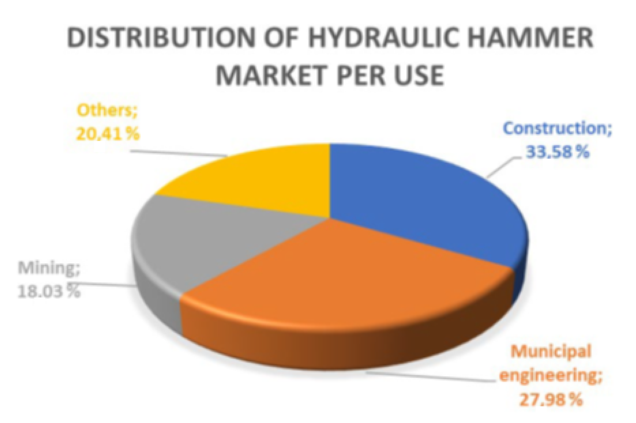
1.1. Market Analysis and Global Players

Following the results of the global market research in [1,2], rock-breaker sales were a little over 1 billion USD in 2017 and are projected to grow by more than 11% during 2018–2023, to nearly 2 billion USD by 2023. This sector of machines manufacturing is spread out because there are five top manufacturers of hydraulic hammers: Sandvik AB, Atlas-Copco (Krupp), Montabert (Joy Global), Furukawa, and Eddie, but their total production takes a total of only 24.29%; hence, there are many local manufacturers in different countries. Europe and China took 56.97% of the global production market of hydraulic hammers as of 2016.
For the application market (see Figure 1), the construction industry has always had largest share (33.58% in 2016). While the sector of municipal engineering and mining industries take 27.98% and 18.03%, respectively.

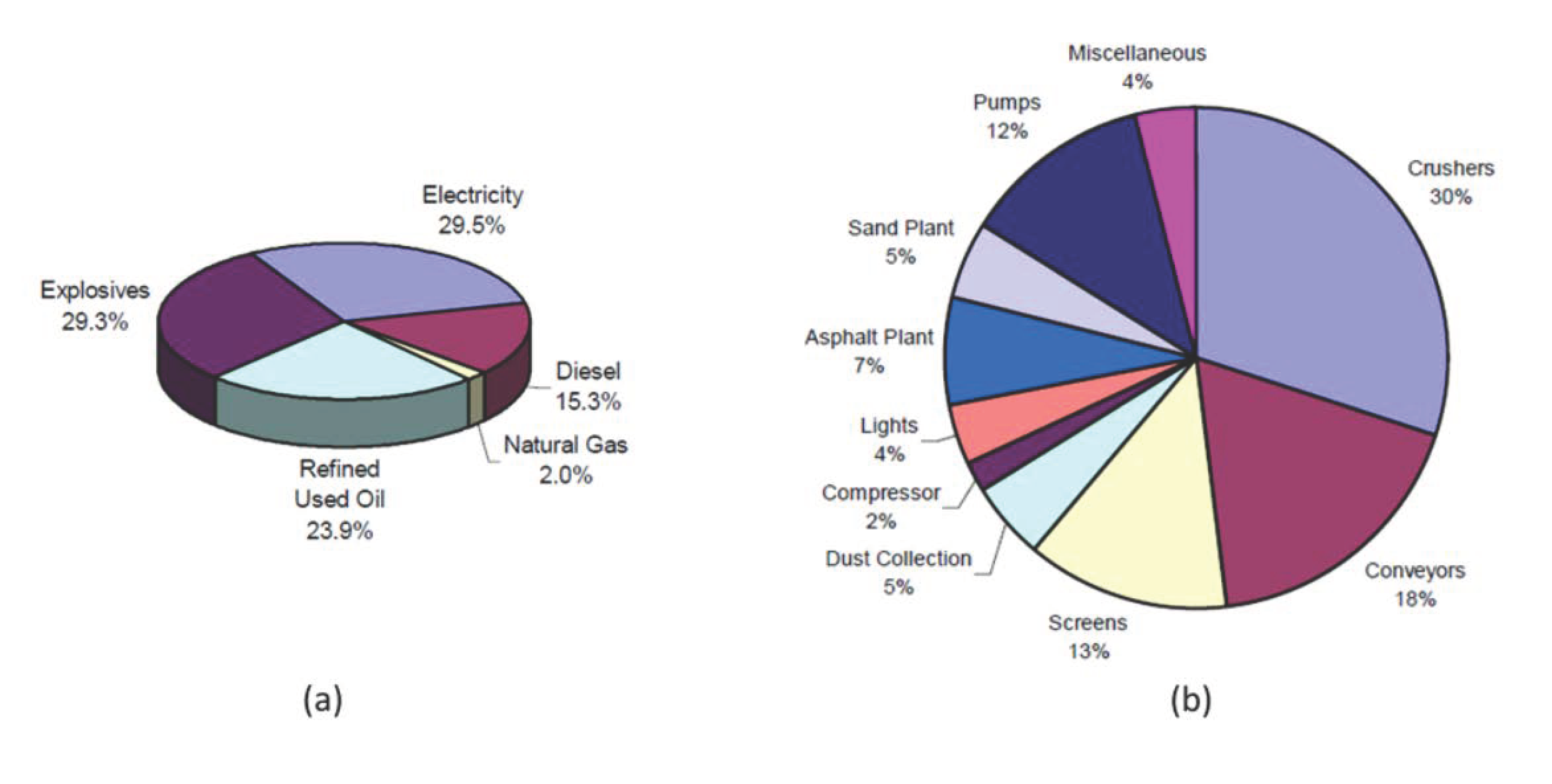
1.2. Energy Consumption

In the mining industry, although the alternative technologies of rock breaking are under consideration [3,4] to replace blasting, the conventional method of drilling and blasting has many advantages from the viewpoint of productivity. On the other hand, there are certain implications due to non-homogeneous geological structures, which resulted in oversized pieces of rocks influencing the rock-breaking hammers’ performance and the fuel consumption of machines.
Opportunities for energy efficiency in the stone and asphalt industry are considered in [5]. The typical breakdown of energy costs in an average-size mining enterprise producing aggregate and the energy consumption at the different stages of crushing operations are represented in Figure 2. Besides electric energy, the biggest part of costs is spent on explosives. Therefore, blasting optimization and planning has significant potential for the economy. Just using the electronic detonators in place of non-electric initiation has shown such benefits as:
  • A 32% decrease in the mean size of rock in the post-blast pile;
  • A 37% increase in the amount of rock of less than 8-inch size;
  • A 25% reduction in digging time to excavate the pile;
  • A 6–10% savings in primary crushing costs measured by power consumption.
The diagram in Figure 3 reveals the energy balance of mining and construction machines with hydraulic and electric hammers. Approximately 47% of the total energy is supplied by the machine combustion engine to the ancillary equipment. According to their average efficiency, a hydraulic pump spends 11.7%, hydraulic piping takes about 12.9% due to losses by throttling, and only 3.7% reaches the breaker. Meanwhile, impact energy constitutes only 8.5% [6].

2. Problem Formulation

Pneumatic and hydraulic actuators have similar dimensions to tubular electric actuators; thus, they constitute an alternative choice for the designers of industrial machines. The force is created by applying pressure to a working gaseous or liquid medium in a cylinder and the piston converts the pressure to a force. Ficarella et al. [7] showed that the key parameter, which is responsible for better hammer performance, is the increased working pressure. This solution has several disadvantages. The most frequently occurring problems in hydraulic hammers during operation and maintenance are as follows:
  • Sealing damage and oil leakage due to wear and surface contamination;
  • Cylinder body deformations due to overloading by high pressure;
  • Possible piston rod deformation under load;
  • Hydraulic oil consumption and utilization;
  • Impossibility of changing hammering parameters online within wide ranges.
Traditional actuators usually use open-loop force control but many applications often require controlled stroke and force, which requires the installation of additional sensors and special wiring with environmental and mechanical protection as well as signal-acquisition hardware. Instead, all these issues can be easily resolved with electric hammers.
An electric hammer based on a tubular linear inductive motor has better accuracy, readiness, and control reliability; it is maintenance-free, has easier energy-supply availability, and does not create any troubles with hydraulic fluid.
The increased costs of hydraulic-hammer operation and maintenance during the full life cycle make their replacement with electric hammering solutions profitable. However, certain considerations have to be taken into account for the successful implementation of innovative drives.
This paper is focused on the analysis of possibilities for the application of linear electric-motor hammering solutions to the rock-breaking process. The analysis of other similar domains is given in the paper to understand better the pros and cons of linear electric motors and potentially new domains for their application.

3. State of the Art

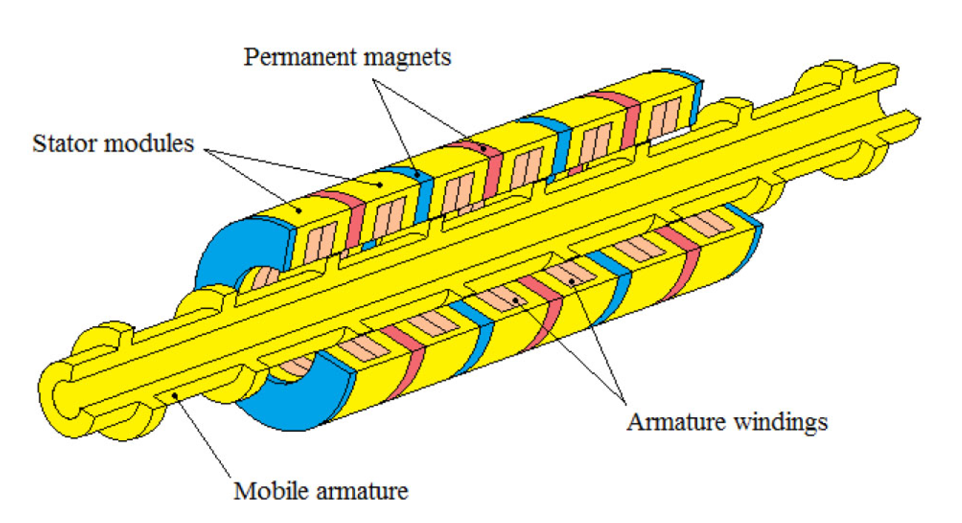
3.1. What Is a Linear Electric Motor

Gieras [8] and Budig [9] classified linear electric motors as a group of special electrical machines that convert electrical energy directly into the mechanical energy of axial motion.
Linear electric motors can drive a linear-motion load without intermediate gears, screws, or crankshafts. Linear electric motors can be classified as follows:
  • DC motors;
  • Induction motors;
  • Synchronous motors, including reluctance and stepping motors;
  • Oscillating motors;
  • Hybrid motors.
The application of DC linear motors is less widespread, save for special automotive applications where a DC supply is provided by the onboard generator. The direct-drive electromagnetic active suspension system is developed by Shen et al. in [10], which consists of a double-stator air-core tubular permanent magnet linear motor (DATPLM) acting in parallel with a coil spring. The proposed DATPLM can also operate in generator mode, which provides an additional energy supply. This suspension system can simultaneously eliminate road disturbances and apply active roll and pitch control. Unlike the existing slotted topologies of magnetic poles (radial, axial), the proposed device has a quasi-Halbach topology with improved dynamic response and very-low-force ripple. Some other studies in this domain are presented by Gysen et al. in [11]. The dynamic model of the car suspension system based on a linear electric motor subjected to sharp loading impacts is proposed by van Casteren et al. in [12]. This model includes non-linear bump stops, actuator saturation, and a combination of Coulomb and viscous friction. The issues of using accelerometers are discussed. The use of the skyhook controller showed improvements in a frequency region of 0.7 to 8 Hz. It is shown that the non-linear model more accurately predicts the acceleration of the car mass.
The most popular are permanent magnet (PM) linear synchronous motors (LSMs) and linear induction motors (LIMs), which are manufactured commercially for many applications. The most known application of LIMs is in transportation based on electric traction systems, where the primary is mounted on the vehicle and the secondary is installed along the track. Linear induction motors are used in cranes for material handling. They are also used for liquid-metal pumping, actuators for door movement, high-voltage circuit breakers, and accelerators for rigs for testing vehicle performance under impacts. In recent years, significant attention has also been paid to LIM applications in kinetic weapons (rail guns). In hammering applications, similar to rail guns, tubular LIMs are used, whose structure is shown in Figure 4.
In the general sense, the stator and the rotor of LIM are known as primary and secondary, respectively. If the primary of the linear induction motor is connected to a three-phase voltage supply, a traveling flux wave is produced, which travels along the primary body. Due to the relative motion between the traveling flux wave and the secondary, a current is induced in the conductor, which also produces a magnetic flux-wave interaction with the traveling flux wave of the primary, resulting in a linear force. Depending on what body is fixed, primary or secondary, the electromagnetic force will move the opposite body in the direction of the traveling flux wave.
The linear synchronous speed v s of the traveling flux wave produced by the primary of the linear induction motor is given by the formula:
v s = 2 f P ,
where f is the frequency of the supply voltage (Hz); and P—pole pitch.
If the LIM is an asynchronous or induction motor, the speed of the secondary is less than the synchronous speed and the difference between the two speeds is known as the slip. The slip of the linear induction motor is given by,
s = ( v s v r ) / v s ,
The speed of the secondary v r in the linear induction motor is given by the formula:
v r = ( 1 s ) v s ,
The linear force or thrust of the linear induction motor is given by the formula:
F = P g a p / v s ,
where P g a p —power at air gap.
Govindpure et al. [14] noted that during the LIM design process, basic equations of rotary induction motors (RIM) are commonly used, but they do not reflect the true merit of LIM. The end effect and edge effects are usually neglected. A double-sided LIM of 12 m in length is designed by the 3D Maxwell software and analyzed at no-load conditions.
The literature analysis shows that modern mining enterprises worldwide are aimed at digitizing and automating mining processes with autonomous working or robotized machines. Although the different versions of the design (Grinchenko [15]) of linear electric motors have been known for a long time (Brittain and Laithwaite [16]), they are still not widely represented in heavy industries such as mining, oil and gas, construction and metallurgy (Kurilin et al. [17]).
The actuators based on linear electric motors are mainly applied in precise manufacturing processes, robots, materials machining centers, additive manufacturing, and laser cutting for working tools positioning and parts moving (Gieras [18], Korendyi et al. [19,20]). The best linear electric motors for such applications are permanent magnet (PM) linear synchronous motors (LSM).
Combined linear induction motors (CLIMs) for moving robotic trolleys in sealed radiation chambers are considered by Tiunov [21]. These motors consist of induction driving units and braking units based on permanent magnets. Acting together, these units make it possible to obtain a low-speed trolley without a complicated control system or frequency converters.
One of LIM’s applications, which can be considered for underground mines, is their combination with hydraulic cylinders in the powered roof supports of a long-wall shear complex. The main reason is to decrease the response time of hydraulic actuators to sharp dynamic loading occurring from the rock (Rudzki et al. [22]).

3.2. Design Optimisation

In most industrial applications, LIM requires a larger air gap as compared to a conventional rotary induction motor; hence, the magnetizing current of LIM is larger than that of a rotary induction motor of the same power. Therefore, the efficiency and the power factor of LIM are lower than that of a conventional induction motor of the same rating. Nasar et al. [23] estimated primary core and solid secondary eddy-current losses in the tubular linear induction motor (TLIM), considering the nonlinear B-H characteristic, hysteresis, and skin effect. Techniques for the parameter determination of the equivalent circuit and performance predictions are developed, which are in good agreement with calculated values.
The optimization of the electrical and mechanical parts of LIMs plays an important role in the reduction in losses and improvement of performance, which increases overall competitiveness in high-power applications.
A tubular linear induction motor (6 kW, 3-phase, 415 V, 50 Hz) is designed and analyzed by Kumar et al. [24] for continuous hammering application. Design analysis was carried out using ANSYS MAXWELL software, which allowed for the simulation of the thrust force, linear speed, and other parameters of the motor. In paper [25], the authors presented the design optimization of an LIM. The objective function of the optimization problem includes power efficiency, output thrust, and the total weight of the device. Various design parameters were used as constraints. Optimization resulted in significant improvements in machine efficiency and output power compared to the known solutions. Machine design and its optimization were carried out with RMxprt software.
In low-power applications of both hydraulic (pneumatic) or electrical drives, e.g., in manual hammers, vibrations and impacts can cause health-related issues for workers. Meanwhile, in large-scale mechanisms, impacts of high amplitudes cause cyclic fatigue and failures of structural elements and impact surrounding buildings, e.g., in pile-driving machines. Therefore, the development of an innovative vibration-damping solutions is of great importance for the safety and durability of hammering machines.
The development of an electric hammer using self-synchronization phenomena is conducted by Bonkobara et al. [26] to address the problem of hand–arm vibration syndrome. The authors showed, based on a dynamic model, that two oscillators acting together can reduce harmful vibration. Some other types of damping principles and technical solutions were also proposed by Harada [27].
Goman et al. [28] describes a mathematical model of interconnected electromechanical and thermal processes in an LIM. The thermal model consisted of eight control volumes on each tooth pitch of the LIM. Model verification was performed using the finite element method and using experimental data. The authors determined the limits of safe operation by considering the unevenness of heating along the length in two cases: natural cooling and forced cooling. For forced cooling, the required values of airflow were determined. For the arc-induction motor of the screw press, the influence of various factors (i.e., of the stroke, the use of a soft start, and the use of forced cooling) on heating was evaluated.
The recent developments patented by Peltola et al. [29,30,31,32] disclose the design of LIM-based devices for different hammering applications. The main efforts of these and many other known inventions are aimed at structural strength capacity, and impact-force increasing for the minimal power supply.

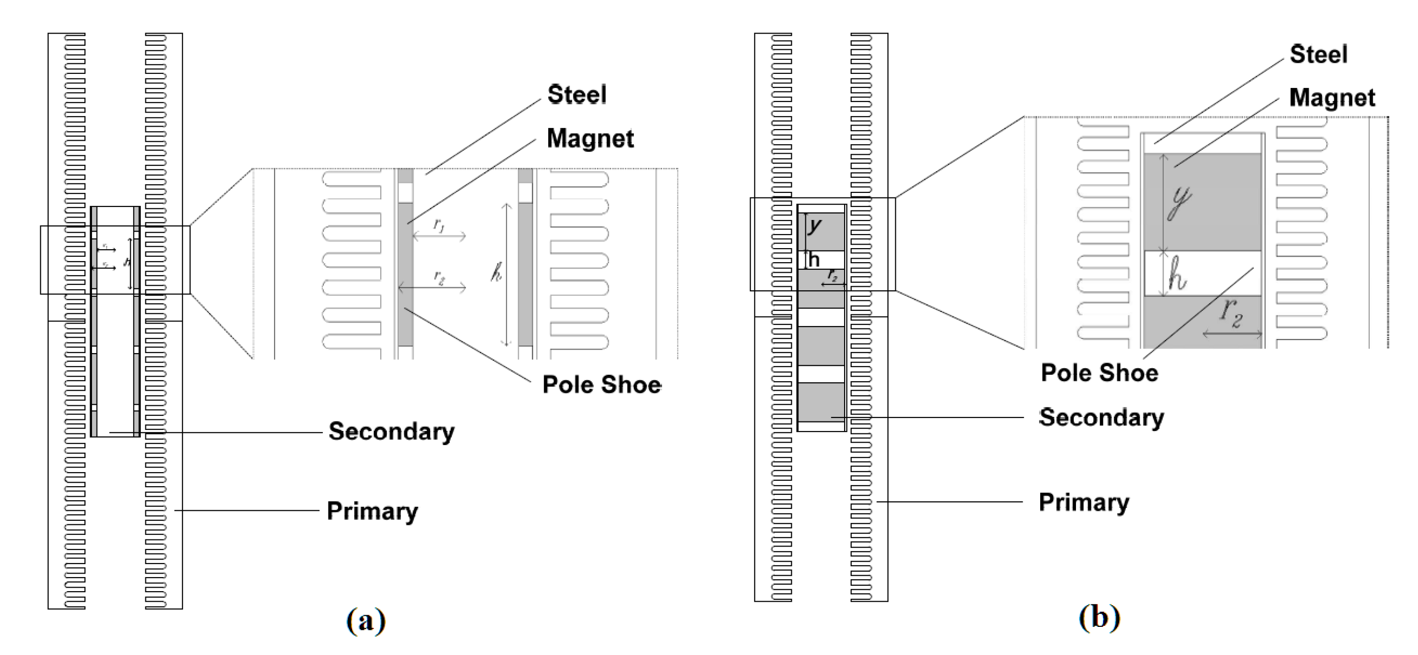
3.3. Material and Topology of Permanent Magnets

The performance of linear electric motors and hammers directly depends on the magnetic properties of permanent magnets. The two possible options—Ferrite and Neodymium-based—are given in Table 1. Although the price of Neodymium magnets is higher, they have superior properties (specific energy, coercive field) in comparison with ferrite magnets (Milanesi [33]). Ferrites have low remanence, are low-energy and have a strong temperature de-rating.
In tubular electric motors, the topology of permanent magnets can be surface-mounted, radially magnetized or axially magnetized. The two main topologies of permanent magnets in linear electric motors—(a) surface-mounted; and (b) buried magnet arrangements—are shown in Figure 5. Both topologies produce similar thrust force under certain geometrical parameters of the electrical machine (van Zyl [34]).
Experimental tests and simulation results of buried magnet topology are shown in Figure 6. We can conclude that the advantage of LIM is in the wide range of force regulation without a significant increase in the required current in the coils. Increasing from about 5 to 10 A results in a greate force by 1000 N. In addition, the DC test gives remarkably higher thrust force than the AC test.
Cogging forces appear as the result of the interaction between the permanent magnets and the steel teeth of the primary section. This cogging force results in a slightly jerky motion of the internal part, which is most noticeable at low speeds and creates a problem in the precise positioning of actuators. Certain methods are developed for cogging-force reduction by Lo et al. [13].
A comparative analysis of two variants of magnet topology was carried out by Wang et al. [35]. The authors concluded that the axially magnetized option has a higher force density, but is more material-consuming. If the same volume of the permanent magnet is supposed, the two topologies provide the same force density. Nevertheless, axially anisotropic rare-earth magnets are usually less expensive and widely used.

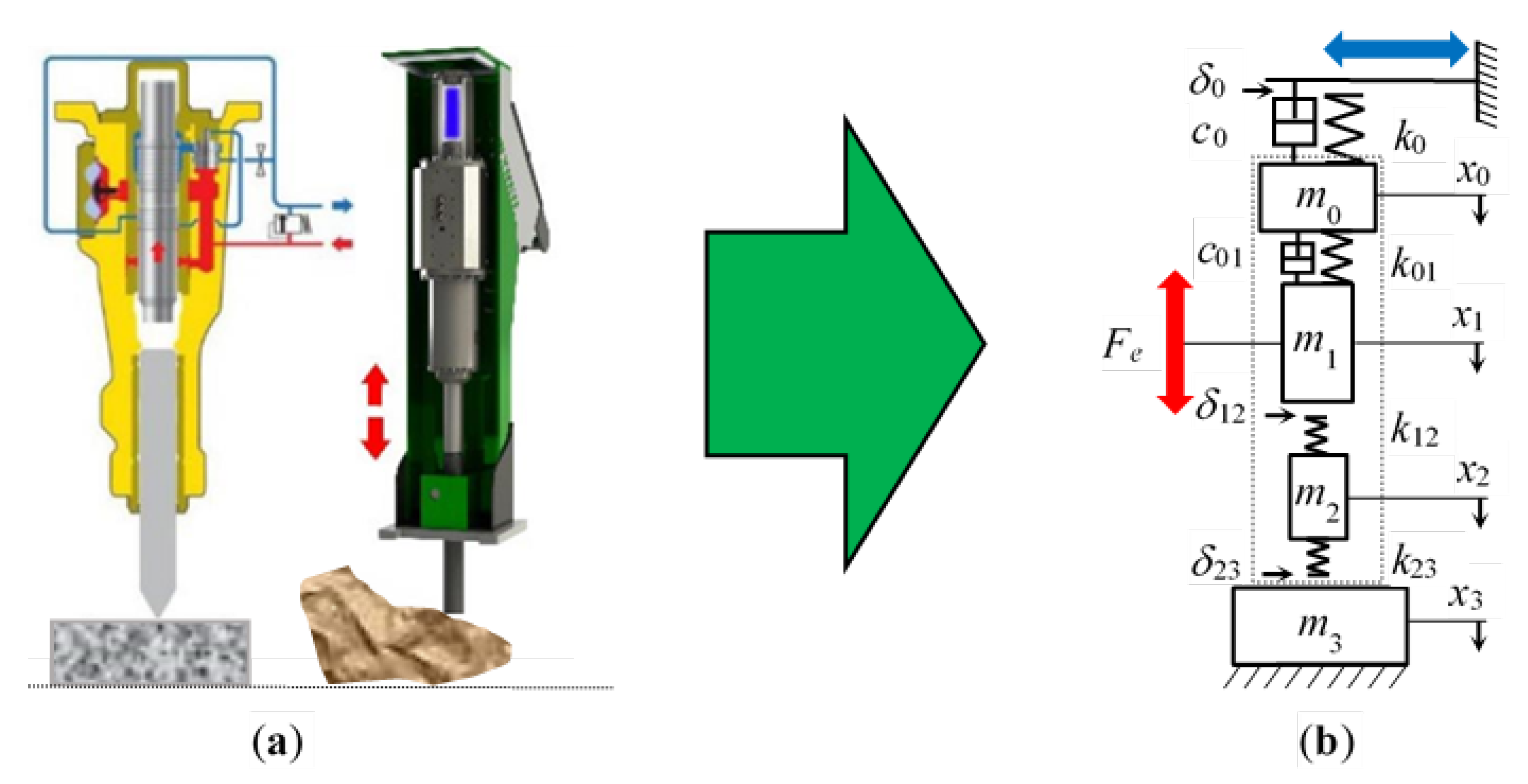
3.4. Dynamical Model of Electric Hammer

Although LIM has many potential applications with periodic motion (air compressors, hydraulic pumps) because of their good reliability, high power density, and convenient maintenance, most studies rarely concentrate on the dynamic behaviour of the linear oscillating actuator such as as a hammer under the action of external loads (Jiao et al. [36], Giuffrida et al. [37]). The main efforts are directed at the simulation of hydraulic pressure distributors and working-cycle optimization (Gorodilov [38]). The multi-body mathematical models of the technological vibratory and impacting units with electromagnetic excitation are developed by Neiman et al. [39,40]. Vibro-impact system dynamics under a Hertzian contact force and the influence of asymmetric electromagnetic actuators are analyzed by Herisanu et al. [41] near the primary resonance.
When modelling the mechanisms containing the hammers, it is important to account for the unavoidable clearances in the joints. Chen et al. [42] developed a planar hydraulic rock-breaker model with multiple joint clearances by combining the hydraulic cylinder model and the clearance in joints. The dynamic simulations showed that multiple clearances can reduce the dynamic responses of a rock breaker producing vibrations and slow movements. In addition, the friction could reduce the rapid vibrations significantly.
Song et al. [43] estimated the impact loads delivered to the housing of a hydraulic breaker quantitatively. Vibrations in the equipment housing, which were experimentally measured, and the impact loads in the chisel were derived from strain gauge measurements of the striking energy.
The proposed authors’ generalized dynamical model of the electric hammer is depicted in Figure 7. This is a non-linear mechanical system with piece-wise linear characteristics of stiffness parameters due to internal clearance in contact of the moving part with the chisel ( δ 12 ). Although the operator intends to press the chisel to the rock before and during crushing, certain external clearance ( δ 23 ) can appear during hammer work. This calculation scheme is similar and applicable to both hydraulic and electrical hammers. The only difference is that excitation force ( F e ) is created either by hydraulic pressure or the electric current in the coils. In addition, both types of hammers have a gas or hydraulic damper ( c 01 ) on the top of the housing ( m 0 ), to accumulate the kinetic energy of the moving part ( m 1 ) and increase its impact on the working tool ( m 2 ). The experimental investigation of linear permanent-magnet actuators with gas springs is conducted by Ummaneni et al. [44].
It is important to note that the energy portion transferred to the rock ( m 3 ) by the moving part ( m 1 ) via the working tool ( m 2 ) depends not only on the contact conditions between colliding bodies but also on the technical condition of the supporting structure; in particular, the excavator or stationary manipulator. The wear of bearings (radial clearances) in the couplings ( δ 0 ) reduces the overall stiffness of the structure and creates additional shocks on its elements, which are damped ( c 0 ) by the hydraulic cylinders of actuators, but still cause further degradation and looseness of joints in manipulators.
During hammer operation, the manipulator stiffness ( k 0 ) is continuously changing, due to the arbitrary regulating of hammer position by a machine operator. When setting the frequency of hammering impacts within a wide range (1–20 Hz), it could coincide with certain natural modes of supporting-structure oscillations. In turn, those modes can also change their frequencies depending on the spatial position of the hammer. Those dynamical processes are similar both in hydraulic and electric hammering, but the supporting structure is less susceptible to higher frequency oscillations in the latter case.
Depending on the shape of the treated material and crushing conditions, i.e., flat surface and stable position or uneven shape on an unstable basement, different chisel ends can be used: cone, blunt, or wedge. Worth noting is that during the operation of the hammers, the shape of the chisel changes significantly but their replacement usually occurs after full failure (rod bending or cracking).

3.5. The Diagnostics and Control of Linear Electric Motors

Since the hammers are subjected to severe impacts, they are susceptible to frequent failures, and diagnostics is of great importance during a crushing machine’s operation. Different kinds of internal faults in linear electric motors as a subclass of electrical machines can be detected by the electrical signature analysis (ESA), motor voltage signature analysis (MVSA), or motor current signature analysis (MCSA). These methods allow the detection of damages not only in electrical parts but in mechanical elements too. Instead, hydraulic actuators including hammers require the installation of additional sensors to measure such parameters as pressure, oil flow, displacement, or acceleration.
The combined modeling and identification of the parameters of a tubular LIM (TLIM) are represented by Agnello et al. [45]. In addition, the TLIM speed control for this specific application is proposed. A fault diagnosis method is proposed by Wang et al. [46] to detect current sensor faults for the primary permanent-magnet linear motor (PPMLM) in the traction system. Only two current sensors are required in this method, and the gain fault and zero-offset fault can be distinguished.
Hydraulic hammers always apply maximum pre-installed impact energy, while the electric hammer can automatically or manually control the impact. To eliminate this shortcoming, a hybrid system of a hydraulic breaker system is suggested by Yoon et al. [47] with optimized impact forces and active control to improve energy efficiency. The characteristics of rock properties are obtained by a proximity sensor which can determine the depth, at which the piston stroke will reach the object. Moreover, a cascade control system for multiple levels of impact points is included and monitoring modules are developed with wireless communication. The field test showed the feasibility of the suggested breaking system. However, the rebuilding of existing hammering systems makes this approach difficult to implement, particularly, in mining machines working in harsh environmental conditions.
The original application of a three-phase LIM as a sensor of the damage in the continuously rolled steel sheet is proposed by Szewczyk and Walasek [48]. A data-based method to monitor linear electro-mechanical actuators is developed by Ruiz-Carcel and Starr [49]. The proposed algorithm uses the electric current and position data, which are typically available from the controller, to detect and diagnose mechanical damage in the actuator. The main parameter from the viewpoint of hammer performance is the impact energy, whose reduction can be a sign of internal damage either in electrical or mechanical parts. There are many methods of impact energy measurements but mainly in laboratory studies on the test rigs (Ficarella et al. [7,50,51], Park et al. [52]).

4. Case Studies of Hammers Applications

4.1. Deep Drilling in Oil And Gas

Percussive-rotary drilling is an effective method for hard-rock drilling. Since hydraulic and pneumatic hammers have many problems in deep core drilling, a new electromagnetic hammer driven by a tube linear motor is introduced by Wu et al. [53]. The problem of the relatively high working temperatures in a deep down hole is considered and its influence on the electromagnetic thrust of the linear motor is analyzed. A model of the linear motor hammer is developed, allowing the authors to analyze the impact power and frequency under different stroke lengths and temperature conditions (see Figure 8). Impact frequency and impact power have an inverse relationship, but the first parameter is non-linearly, and the second is linearly, dependent. The impact stroke has an influence mainly below 50 mm.
The prototype test showed that the linear motor hammer can reach and even exceed the hydraulic hammer of the same diameter, especially in the low-frequency range. Wu et al. [54], using the developed model, estimated the loss of permanent magnet, coil resistance variation, and coil thermal expansion within the temperature range from 20 °C to 300 °C. The obtained results of model simulations showed the by less than 31% trust reduced by copper loss; the thrust reduced by 18% by the permanent magnet loss. On the other hand, the effect of the air-gap change by thermal expansion can be practically neglected.
A tubular linear permanent magnet motor used for drilling is described by Zhang et al. [55]. The advantage of this motor is in the gas springs, which allow for increasing the electric power transmitted to rock without additional elements. A mathematical model of the hammering process is composed and the dynamics of oscillatory motions are analyzed. The dynamic response of no-load mode and load mode is compared. Simulation results show the advantages of the additional spring in comparison to a simple forced motion of the hammer.
In the rigs for blasting holes, and drilling in the underground mines and open pit mines, there are many hydraulic cylinders (Wodecki [56]). They can be naturally substituted with LIMs of appropriate scale because usually the electric power is supplied to these drilling machines by additional connected cables, which can be used for electric units too. In this case, the percussion force, thrust force and rotation torque can be combined in one device. An example of an electric-hammer application for the drilling of blast holes is given by Petit [57]. In the case of electric percussive drilling machines, the diagnostics of bit wear become easier (Zhang et al. [58], Antonucci et al. [59]), due to simple hardware and software tools for operational-parameter recording and electrical-signal interpretation.
A comparative study of pneumatic and electric drilling devices regarding productivity, noise, vibration, and created dust is conducted by Rempel et al. [60]. The experiments showed that noise, vibration, and respirable dust levels were higher (by 13 dB, 5×, and 40×) with the pneumatic drill, while there were no differences in drilling productivity (ROP—rate of penetration) between these two types of units of similar mass.

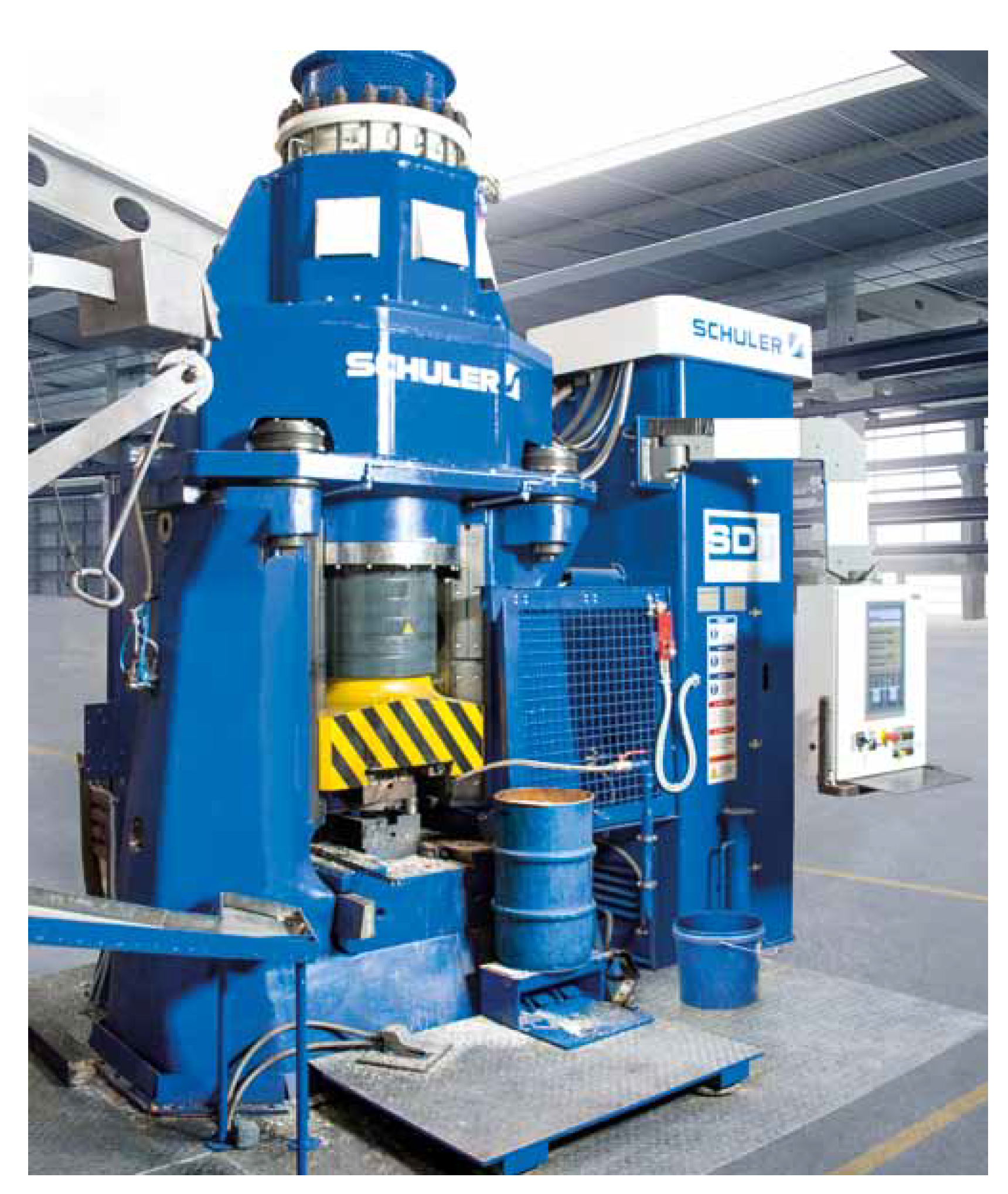
4.2. Metallurgical Forging Press

Probably, the most spectacular example of a linear electric motor application is the metallurgical forging press shown in Figure 9. Due to the implementation of electrical driving technology instead of traditional hydraulic drive, many technological benefits have become available (Schuler [61]).
The embedded electronic control system can automatically adjust the energy of impact and the number of necessary forging blows in accordance with the actual state after each cycle, until the final part thickness is achieved. The influence of working-tool wear on process accuracy can, therefore, be compensated by regulating the energy input. This approach and design of an electrically driven press improves product quality and makes it possible to optimize the technological process.

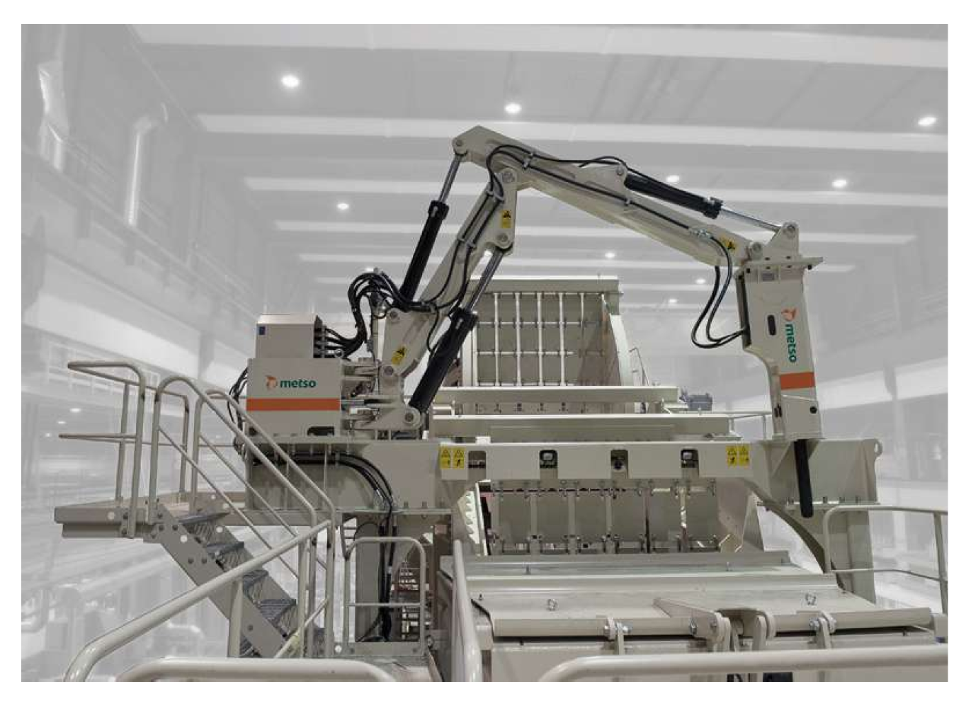
4.3. Sieving Screens

Traditionally, hydraulic crushing hammers are used at the first stage of sieving screens (see Figure 10), to prevent the passing of oversized rocks for further sieving and other technological processes (Bembenek et al. [62], Korendiy et al. [63]).
One more industrial application of linear motors is for actuators of vibration in sieving machines. Such types of drives allow the manufacturing of equipment with very low energy consumption and material costs (Makarov et al. [65]).
The main problem, which should be solved in the actuators of sieving screens and other vibrating machines for bulk-material processing, is the tuning of frequency, amplitude, and trajectory (orbit) in the course of the operation when the properties of the sieved media change (Gursky et al. [66]) and these changes are quite difficult to predict or track (Bardzinski et al. [67,68,69]). Screen-parameter tuning is difficult to realize in the standard design with unbalanced vibrators and requires different technical solutions (Gurski et al. [70,71]). Using LIM as actuators can replace special spring supports requiring complicated methods of diagnostics (Krot et al. [72]) and, thus, reduce maintenance actions and cost.
The linear electric motors used as the actuators of vibrating machines can easily change all the above-mentioned technological parameters by the signals from accelerometers, realizing efficient feedback loop control. Aipov et al. [73] developed a sieve mill for a grain cleaning machine driven by a linear induction motor. It is shown that the advantage of a linear induction motor compared to standard drive designs is significantly less metal consumption for drive shafts, transmission elements, connecting shafts, bearings, and structure. Hence, energy consumption is also reduced due to the pulse drive, which makes it possible to perform technological-parameter regulation within a wide range for various crops with various physical and mechanical parameters.

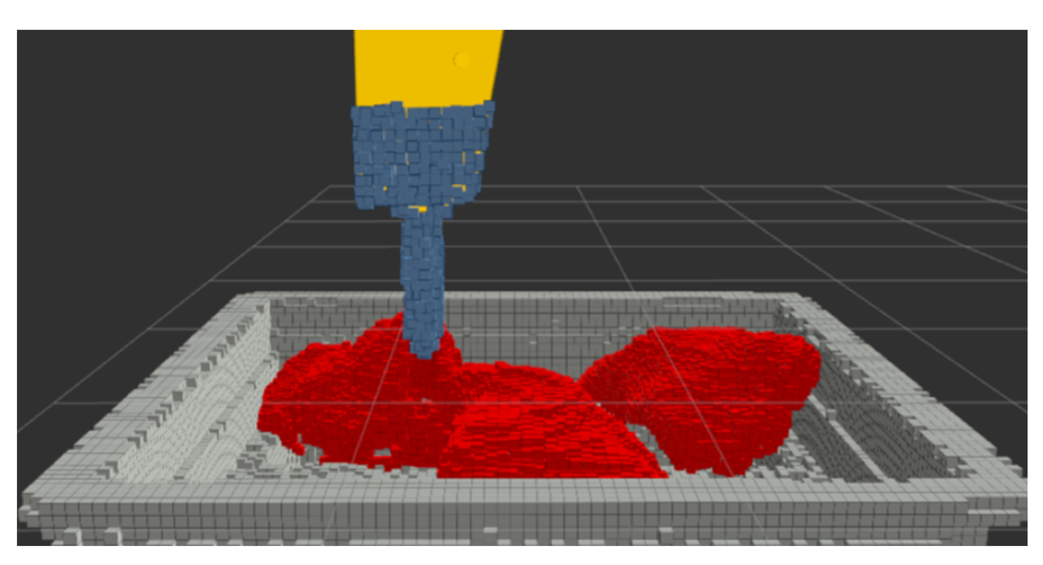
4.4. Crushing Hammers in Mining

By different estimates, depending on variable geological conditions and mineral production technologies, about 15% of blasted rocks are oversized for further processing, including transportation by heavy vehicles and belt conveyors (Doroszuk et al. [74], Król et al. [75]), screening or comminution, which can cause machines failures or additional energy consumption, e.g., in tumbling mills (Góralczyk et al. [76], Bortnowski [77]).
The influence of the particle-size distribution of excavated material on hydraulic excavator productivity was experimentally investigated by Kujundžić et al. [78] by photogrammetric method and the excavator working cycle was measured by analysis of video recordings. It was discovered that a larger number of fine particles in granular materials with a higher uniformity increases the volume of the bucket load. In underground mines, the oversize pieces of the blasted ore generate additional loads on the structural elements and transmission of load–haul–dump (LHD) vehicles (Krot et al. [79]).
The concept of “active bucket” is proposed by Gorodilov et al. [80,81] for open-pit mining excavators, which supposes the dynamic impacts (vibrational or low-frequency) of buckets on the rock mass of high strength. Any bucket element (front wall, teeth) can be equipped with a dynamic actuator (electromagnetic, hydromechanical, pneumatic or hydraulic).
Unlike other types of crushers (jaw, cone, gyratory) designed for fine-fraction production, impact hammers, both stationary and mobile, are intended to be used at the first stage of blasted-rock-pieces treatment.
The energy consumption using the laboratory vibratory jaw crusher is estimated by Mazur [82] for limestone and diabase. In this study, electrical energy is measured as a function of changing parameters of the vibratory crusher: jaw stroke, the outlet gap section, and the frequency of jaw vibration. The author compared the expected crushing energy by the Bond hypothesis with the measured values and observed large differences between them. The crushing work index is determined in [82] on the basis of Bond’s formula [83]:
W I v = E j v 10 ( 1 / D 80 1 / d 80 ) ,
where WI v —crushing work index (kWh/Mg); E j v —specific energy of crushing (kWh/Mg); D 80 , d 80 —control grain size for the feed and the crushing product, respectively (μm).
By analogy with the comminution process, the smaller the pieces after the material crushing, the more energy is required for the hammering process. Hence, the component ( 1 / D 80 1 / d 80 ) could be a measure of crushing-process intensity. However, this parameter is well-suited for the small and fine fractions of materials with more similar structures, while its application for crushing large oversized pieces of rock may have a significant bias from theoretical values due to the action of many factors, e.g., piece position; chisel position on the rock (middle or end), bit shape, edge wear; impact direction (angle of inclination), rock stratification).

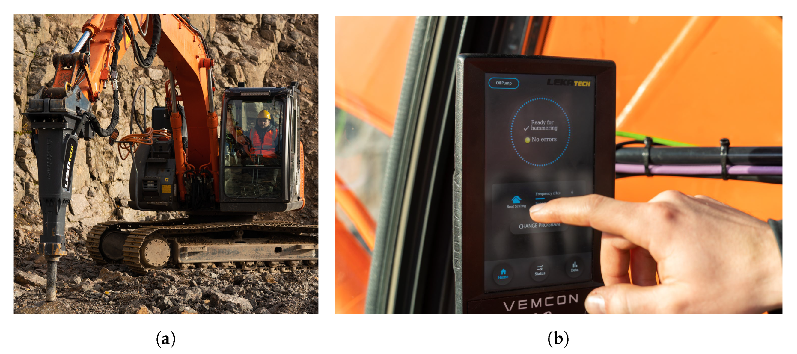
4.5. Application of Electric Hammers in Mining

The electric hammers based on a tubular linear asynchronous motor have an armature, which produces an oscillating movement. To increase the power indices, the design can include a pneumatic power accumulator, whose characteristics are matched with the parameters of the linear asynchronous motor. In this way, the one-sided movement of the linear asynchronous motor armature under the action of the electromagnetic forces is provided, while the reversing operation happens due to a pneumatic spring. The pneumatic shock absorber also protects the base unit from shock impacts.
The energy to the oversize piece of rock is transmitted from the armature to a separate bit (chisel with a hard cone or wedge) via a certain clearance where the armature rod is accelerated to gain the appropriate kinetic energy. A required working voltage (DC or AC) is supplied to the linear electric motor and due to the traveling electromagnetic field in the stator, the armature goes up and down.
In the case of helical steel springs or gas accumulators, the moving armature compresses a spring or gas and when the forces acting on the armature body reach equilibrium at the upper position, the linear motor stator can be periodic with a certain periodicity disconnected from the line by a signal from the power controller or special sensor. Then, the armature moves down and applies an impact to the tool. The energy of a single impact may be controlled by changing the volume of the gas accumulator (stiffness of the spring) and the function of the supplied voltage (time that the motor for moving the armature is turned on).
The linear electric motor hammers do not require secondary energy converters (compressors, oil pumps, hydraulic lines), which increase the energy efficiency of the hammer since they are powered directly by the main electric lines. The mechanical impact energy of the electric hammer achieved by Kabachkov et al. [84] reached 18,500 J and the crushed volume of oversize magnesite up to 4.5 m 3 . The hammer power supply voltage is 380 V; the total mass of the hammer is 3000 kg; impacting part mass is 110 kg; the mass of the tool is 250 kg and the diameter is 0.2 m. The pieces were treated at the frequency of 60–100 min 1 (1–2 Hz). The conducted tests showed that after a series of impacts by the wedge (lance) end of the tool, a pulverized layer appears on the surface, which absorbs the energy of the impacts. The total number of impacts for the largest pieces was up to 12–14 and even 1–2 impacts were enough for small-piece (0.5–1.5 m 3 ) crushing with the impact of maximum energy.
In the construction industry, hammers are used for hard-concrete-element demolition (walls, foundations). The use of electric hammers to break up concrete foundations in the process of the overhaul and replacement of production equipment is described by Minaev et al. [85]. The cooling system of the electric hammer is designed for a duty factor of 15%. In the experiments, the authors suspended a hammer from an overhead crane in the workshop.
The operators of both hydraulic and electric hammers should put the impact tool on the oversize piece at a straight angle to prevent its sliding over the surface and possible bending. The oversized piece of rock should be crushed starting from the edge and, step by step, continued to the center. To prevent tool-bit heating, which promotes its strength reduction and excessive wear, a maximum of only 10–20 strikes should be produced with a subsequent stopping. The maintenance staff should provide scheduled lubrication of the tool and bit sharpening.
The current challenges for underground and open-pit mining include the improvement of safety as well as the optimization of production processes, reducing bottlenecks and downtime while increasing the operational efficiency of the machines. To achieve these goals, the hydraulic hammer can be remotely controlled, allowing for a more comfortable and safe work environment.
A specific stage in the production chain of an underground copper mine is a place where blasted bulk material is transported by the LHD vehicles and heavy trucks to the conveying system. Such a place is called a dumping point (see Figure 11), which is equipped with a screen classifying the material into coarse and fine fractions. The process of bulk material delivery has a cyclic schedule (Krot et al. [86]) and the performance of a hydraulic hammer breaking oversized rocks to prevent damage to the conveyor belt affects the overall productivity of the mine. Therefore, to make the hammering process continuous, a prototype test rig has been proposed for debugging the algorithm for the automatic detection of oversized rocks, crushing them along with sweeping of bulk material (Stefanik et al. [87]). The whole view of the hydraulic manipulator with a hammer is depicted in Figure 12.
To improve the efficiency of the hydraulic system at the dumping point, an approach is proposed by Siwulski et al. [89] based on the analytical model of a stationary rock-breaking machine (see parameters in Table 2). The results of the calculations showed benefits from a modified hydraulic system in energy consumption.
The concept of process monitoring and automation with visual sensors for autonomous operation and remote hammer control in such applications is represented by Krauze et al. [90]. The development of a telerobotic rock breaker is also described by Duff et al. [91].
A similar system for the automatic control of impact hammers used in underground mines is described by Cardenas et al. [92]. The position and angle are determined at which the impact hammer must strike a rock to break it. The automatic system uses sensor data composed of point clouds and images. The rock segmentation subsystem receives identifiers of the rock pieces above the grizzly screen and transfers information to a pose generation subsystem, which produces a list of rock-breaking targets. Then, it selects the best candidates among them. The conducted experiments showed the efficiency of the developed system.
Poor visibility in the underground environment may result in a collision between the hammer and the grizzly screen covered by fine fractions of bulk material. To prevent machine damage, Correa et al. [93] developed the haptic tele-operation system based on a 3D LIDAR scanning and point-cloud model of the environment, which can estimate repulsion forces transferred to the operator (see Figure 13).
Regarding the autonomous operation of impact hammers, although research started more than twenty years ago (Takahashi et al. [94]), the reported results are still not satisfactory for the application of this technology in a real mining environment. Lampinen et al. [95] obtained an average success rate of only 34% in the task of the remote control of rock breaking.
All such automated and semi-autonomous systems for hydraulic hammer positioning have certain functional limitations related to the absence of additional control of impact force and frequency, which can be realized in the electric hammers.

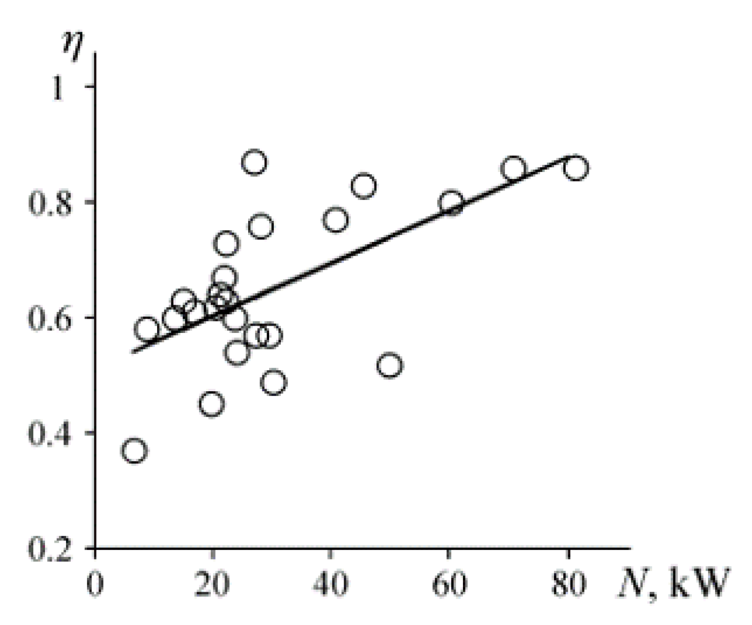
4.6. Prediction of the Impact-Hammer Performance

While performing crushing operations, the constant setting of breaking force causes energy dissipation due to the various strengths of the material. In cases when the overall situation is not monitored, this may damage the mechanical and hydraulic components of the system. Frequent maintenance and parts replacement can result in costly losses and increased downtime. Therefore, a novel approach to rock breaking is needed that is able to predict the treated material properties in order to set an optimal impact force and frequency of hammer impacts.
There are many kinds of rock mass classifications and ratings (Bieniawski [96], Aksoy [97]). The typical classification of rock materials by the unconfined compressive strength (UCS), which is most applicable for separated rock pieces, is given in Table 3.
The main dynamical parameters in the rock-crushing process by hammers are as follows: strike length L; impact energy E; impact frequency f; and impact efficiency η . For hard rocks, longer strokes are better, while shorter and higher frequency impacts are used for softer rocks to reduce unnecessary energy losses, which improves the performance and durability of machine parts (Yoon et al. [47]).
Mezentsev [98] determined the crushing efficiency of a hydraulic hammer as follows:
η = A Q c Δ p ,
where A—crushing energy; Q c —volumetric consumption in a cycle; and Δ p —difference in inlet/outlet pressure of the hammer. The relation of hammer efficiency with power is shown in Figure 14. It was concluded in [98] that efficiency rises with power but, at the same time, greater power corresponds to higher frequencies (6.0–11.7 Hz) for almost equal-impact energy values. The author concluded that the most influencing factor of efficiency is the hydraulic distributor and the most advanced devices can provide a maximum of 60–70% efficiency.
Crushing energy delivered to a working tool is determined (but not equal to) by the kinetic energy of the moving part of the hammer:
E = m v 2 2 ,
where m—mass of moving part; and v—velocity at the moment of impact.
However, not all of the kinetic energy generated by the moving part is transferred to the rock mass. It depends on the rebound rate in the contacts with the working tool (back end of the chisel) and with the rock surface (front end of the chisel). In mechanics, for collision with a stationary surface, this dynamic process is described by the coefficient of restitution (CR):
C R = u v ,
where u—speed after impact; and v—speed before impact. Its values correspond to two marginal cases of collision: 0—absolutely inelastic impact; and 1—absolutely elastic impact. The latter case is preferable in both contacts from the viewpoint of rock-crushing efficiency by the hammer. This coefficient does not account for the masses of colliding bodies; however, such influence exists.
The hardening of the working-tool material made of alloy steel at the top end can change the CR after a long series of impacts. Therefore, material properties (steel grades) of an electric core should be correctly chosen (or bottom-end hardened) to provide durability.
The other relations describing the hammering process depend on design parameters: The acceleration of the moving part:
a = F e m ,
The maximum velocity before impact:
V m a x = a t ,
The time of one-way motion (half-period of vibration):
t = 2 S a ,
The required frequency of hammer:
f = 1 2 t ,
where m—is the mass of the moving part; F e —thrust force acting on the moving part from the electric system; and S—the distance between the working tool’s upper end and the moving part’s lower end in its upper position (see δ 12 in Figure 7b).
Certain efforts have been undertaken to predict the properties of crushed materials to increase the efficiency of breaking hammers (Aksoy et al. [99], Ismael et al. [100], Kucuk et al. [101], Tumac et al. [102]). Research on the resonance characteristics of rock material under harmonic excitation is represented by Li et al. [103], where the influence of excitation frequency, the rock properties and dimensions are analyzed using FEM. The mass and shape of the rock are the main factors affecting its resonance frequency, besides the material properties. A 3D FEM model of impact is developed and experimentally verified by Chiang et al. [104], which permits simulation of the energy transmission to the rock via the bit–rock interaction, and to analyze the process of rock fragmentation. The majority of studies in this domain are devoted to the small-size bodies’ (projectiles) penetration into different concrete walls with comparatively low energy. Anyway, results obtained by Higan et al. [105] can be useful in hammering analysis. For example, more dense materials produce less fractured masses and have larger dominant fragment sizes. The tip geometry influenced the penetration depth, which was in quadratic relation with the initial kinetic energy (Kumano et al. [106]). The dominant rock properties affecting the penetration rate in percussive drilling are determined by Kahraman et al. [107] and they are uniaxial compressive strength, the Brazilian tensile strength, the point load strength and the Schmidt hammer value. However, the rate of penetration has weak correlation with both elastic modulus and density, and the absence of correlation was noted with P-wave velocity.
The results of experimental and numerical studies of the impact breakage of granite with high ejection velocities are represented by Zhang et al. [108]. The dependencies of the high-speed collision parameters granite damage ratio ( α d ) and energy dissipation ( E n d ) on impact velocity are shown in Figure 15. Although the usual range of hammer impact velocities is less than shown in these graphs, the general dependencies (almost linear) will also be valid for low-frequency hammering applications.
Results of the experimental investigation are reported by Gorodilov and Efimov [109,110] of shock pulses in the piston-bit system in interaction with rock mass. The rock mass was simulated by a marble block of 0.95 × 0.95 × 1.5 m 3 in size and 400 kg in weight. The test cylindrical pistons (3.1, 5 and 16 kg and 565 mm) were impacted by a pendulum hammer into the bits (5 and 9.6 kg and 160 mm) with a tapered end (30 mm length and 60 angle), which was tightly contacted with a rock. The pre-blow velocities of the pistons (5.01, 4.01, 2.25 m/s) were set to obtain similar impact energies for the different weights. The highest efficiency of rock fracture is observed in the piston–bit pair of 5.5–5 kg weight, while the lightest piston (3.1 kg) has the highest recoil and the weakest fracture efficiency. The other two pistons have small recoil, which corresponds to the higher energy transfer coefficient to the bit. The shock duration (up to negative velocity moment) is 0.1 ms for the 5 kg piston and 0.6 ms for the heavier piston. The motion patterns of the 3.1 and 5.5 kg pistons differ from the 16 kg piston; namely, lighter pistons exhibit oscillations with a period close to the double wave travel time in these pistons. For the heavier piston, such oscillations were almost invisible. The logical continuation of these results is the development of a hammer design methodology and the creation of a control system adaptable to material properties (Gorodilov et al. [111]).
The Leeb hardness test (LHT) with a test value of LD for rock materials is investigated by Corkum et al. [112]. An updated methodology is developed and the correlation of Leeb hardness LD with UCS units is shown. Instead of manual measurements with special tools according to ASTM ASTM D5873-14 [113], this methodology can be efficiently implemented for automatic online monitoring and process control in electric hammers with additional sensors, e.g., proximity meters (Yoon et al. [47]).

5. Experiments on the Electric Hammer

The previous studies of the electric hammer of Lekatech Oy were conducted by Mayer [114] and Korhonen [115] concerning technical issues and to ensure the electric hammer complies with requirements set for the European Economic Area and product safety for North American markets (Ukkola [116]).
The current research project being carried out by the authors is related to:
  • Performance assessment of the electric hammer in the various geological conditions of mining companies in Poland, Finland, and Spain;
  • Measurement and collection of operational process data;
  • Checking the reliability of electric-hammer elements in the conditions of underground and opencast mines;
  • Determination of optimal controlled vibration parameters for various materials and grinding tasks.
Accessories required for the electric-hammer operation are as follows: cooling system (not always necessary), inverter, rectifier, fuses, relays, and chisel lubrication unit, which were provided for the hammer installed on the excavator in a separate box (see Figure 16a). In the pilot LEH design, the user interface is organized via touch screen PLC CPX-Terminal-Vemcon 7” (see Figure 16b).
The LEH’s main power is 500 V AC. This is converted to DC by the passive rectifier, after which its DC voltage may change a little. The inverter then changes the current back to AC, according to which mode the hammer is controlled. This AC is fully controlled by PLC and allows the LEH to produce impacts with many different frequencies and energies (see Table 4). Once the hammer’s mode (frequency and impact energy) has been selected from the terminal, the joystick button (foot pedal) is used to operate the hammer, if the tool is pressed down, and the tool limit switch is, hence, on. Oil and water cooling happens periodically or if the respective temperatures become too high.
The series of experiments were conducted with different frequencies of impacts and chisel end shapes (Mayer [114]). The graphs of impacts and corresponding kinetic energy of the electric hammer are shown in Figure 17 for the frequency of 18 Hz and 1 s of time duration. Every cycle of hammering certainly shows individual patterns of impacts and the amplitudes of vibrations depending on the current state of the treated material (granite). In addition, reinforced concrete samples were used in the experiments.
From these represented graphs of dynamical parameters, it is noted that after the impact on the material, the chisel rebounds, which produces corresponding peaks in velocity and acceleration signals. However, these high-frequency jumps of small amplitude are not visible in the position signal due to a double integration of the original signal. Since the kinetic energy is calculated by the velocity, this signal also exhibits certain signs of chisel rebounds from the treated material surface.
The time-domain graph of power consumption by the electric hammer at the impact frequency of 18 Hz is shown in Figure 18. The power-consumption graphs show that the power consumption of the inverter is constant when the moving-part position goes up and decreases quickly to zero as the mover is accelerated rapidly downwards onto the tool.
The kinetic energy of the actuator, as determined by the vibration measurements at the top of the hammer, is highest at frequency settings of 0.9 and 5 Hz (see Figure 19).
Depending on the frequency, type of processed material, and shape of the crushing tool (cone, blunt, wedge), the time to fracture varies significantly (see Figure 20).

6. Discussion

Many technological operations in mining, oil and gas, raw-materials processing, construction (demolition), and other heavy industries demand certain solutions to increase productivity, energy efficiency, and personnel safety along with a reduction in maintenance costs, and environmental impact (exhaust gases emissions, wastes utilization). To satisfy these frequently contradictory requirements, innovative technical solutions based on ubiquitous digitization, automation, and the electrification of machines have been proposed and implemented in recent years.
For many types of technological machines, where, traditionally, hydraulic drives were used including hammers, designers are trying to modify them with electrical counterparts (Wagner [119]). However, large-scale electric hammers are not yet enough widely used in industry due to a lack of producers and on-site investigations and comparison with hydraulic analogs of the same power and productivity.
For the correct comparison of the hydraulic breaking hammer and linear motor electric hammer in industrial conditions, the complexity of the process and the uneven conditions in the experiment should be taken into account. Many uncertainties have resulted from uncontrolled factors (e.g., human actions, inhomogeneity of the rock, and the content of oversized pieces). However, being aware of the limitations and adopting certain simplifying assumptions, the comparison can be conducted on the basis of:
  • Two separate experiments for both types of hammers in similar working conditions;
  • The same mass of spoil (1–5 Mg), grain size (>50 cm), rock type (the same part of the deposit);
  • Hammer settings (frequency, energy, etc.) taking into account hydraulic hammer limitations (no parameters adjustment);
  • Preferably the same experienced operator in both cases;
  • Video recordings of both experiments.
Electric power supply for new hammers in the on-surface and underground applications for stationary manipulators (dumping points, sieving screens) is not a problem. For mobile machines, additional cabling should be provided such as in reinforced bolting installation and blast-hole drilling machines.
Although electric hammers will be subjected to excessive impacts, their durability is higher and maintenance costs are lower than the hydraulic units. Additional savings are expected from the lower amount of waste hydraulic oil for utilization. In the case of diesel-engine-powered machines, fewer exhaust-gas (NOx) emissions and, simultaneously, higher energy efficiency and fuel consumption are provided.
The main advantage of electric hammers is the possibility to control (adjust) the impact power and working frequency depending on the hardness and morphology of the treated rock material. This direction needs further development from the viewpoint of appropriate sensors and methods of material properties detection. Using visual methods for hammer control may improve tele-operation and, finally, create efficient autonomous solutions for personnel safety and comfort in harsh environmental conditions.
Probably, the only application where linear electric motor actuators are not quite suitable for hydraulic-cylinder replacement is the large-scale roof supports subjected to constant high static and dynamic loads (Szurgacz [120,121]). Instead, the combination of hydraulic cylinders and linear electric motor actuators may bring new functional benefits in the case of meeting explosion safety regulations in underground coal mines.

7. Conclusions

The conducted review of available literature and some preliminary experiments on the linear electric motor hammer have shown that this solution has many advantages and certain complications for implementation in the industry.
In this paper, we considered the most critical problems related to the design, performance, control, dynamics, and materials of electric hammers.
We claim that hydraulic hammers’ substitution with fully electric hammers, at least in mining and construction (structures demolition), is a prospective approach allowing a significant reduction in the energy consumption and maintenance costs of appropriate machines. Certainly, the replacement of hydraulic hammers should be performed close to their lifetime. Nevertheless, the short period of return on investments (1–2 years) makes electric hammers beneficial, especially in enterprises with a big fleet of machines. The only additional investment required for electric-hammer adaptation is the cables and probably power supply points, which can also be used in other operations.
The significance of the comparison of the two types of hammers is in achieving a more clear understanding of what benefits can be achieved not only in energy saving and environmental-impact reduction but also in the overall performance improvement of raw-materials processing. Namely, preferably, the automatic or manual control of shock energy, the amplitude of stroke, and frequency of impacts depending on the rock properties, size of pieces, and surrounding conditions. To increase the effect of breaking-machine digitization, additional sensors are quite easy to integrate into an electric hammer, more than in a hydraulic counterpart.
We mainly deal here with important problems from a practical perspective; however, a lot of scientific tasks can be formulated aimed at further improvement of electric hammers’ design. For example, an investigation of higher temperatures, humidity, and intensive impacts in underground mines where machine maintenance is complicated. Durability is a critical parameter of any new mechanism intended for implementation, which will be considered first by the technical staff of enterprises.

Author Contributions

Conceptualization, J.P., T.M. and R.Z.; methodology, P.K., A.W. and R.Z.; software, T.M.; formal analysis, R.Z.; investigation, A.W. and P.K.; resources, J.P.; data curation, A.W.; writing—original draft preparation, P.K., A.W. and R.Z.; writing—review and editing, P.K., A.W. and R.Z.; visualization, P.K. and T.M.; supervision, R.Z. All authors have read and agreed to the published version of the manuscript.

Funding

This activity has received funding from the European Institute of Innovation and Technology (EIT), a body of the European Union, under the Horizon 2020, the EU Framework Programme for Research and Innovation. This work is supported by EIT RawMaterials GmbH under Framework Partnership Agreement No. 21016 (ECHO: Electrical Computerised Hammering Operator).

Data Availability Statement

The measurement data presented in this study are not publicly available due to restrictions of privacy.

Conflicts of Interest

The authors declare no conflict of interest.

References

  1. Global Rock Breaker Market. Competition Forecast and Opportunities, 2013–2023. Available online: https://www.techsciresearch.com/report/rock-breaker-market/3530.html (accessed on 24 October 2022).
  2. Global Hydraulic Hammer Market 2018 by Manufacturers, Regions, Type and Application, Forecast to 2023. Available online: https://www.absolutereports.com/global-hydraulic-hammer-market-13679807 (accessed on 24 October 2022).
  3. Tatiya, R.R. Surface and Underground Excavations: Methods, Techniques and Equipment; CRC Press: Boca Raton, FL, USA, 2005. [Google Scholar] [CrossRef]
  4. Zhou, H.; Xie, X.; Feng, Y. Rock breaking methods to replace blasting. IOP Conf. Ser. Mater. Sci. Eng. 2018, 322, 022014. [Google Scholar] [CrossRef]
  5. Moray, S.; Throop, N.; Seryak, J.; Schmidt, C.; Fisher, C.; D’Antonio, M. Energy efficiency opportunities in the stone and asphalt industry. In Proceedings of the Twenty-Eighth Industrial Energy Technology Conference, New Orleans, LA, USA; 2006; pp. 71–83. [Google Scholar]
  6. Vukovic, M.; Leifeld, R.; Murrenhoff, H. Reducing Fuel Consumption in Hydraulic Excavators—A Comprehensive Analysis. Energies 2017, 10, 687. [Google Scholar] [CrossRef] [Green Version]
  7. Ficarella, A.; Giuffrida, A.; Laforgia, D. The Effects of Distributor and Striking Mass on the Performance of a Hydraulic Impact Machine. In Proceedings of the Commercial Vehicle Engineering Congress & Exhibition, Rosemont, IL, USA, 7–9 October 2008. [Google Scholar] [CrossRef]
  8. Gieras, B.F. Linear Electric Motors. Electric Power Generation, Transmission, and Distribution: The Electric Power Engineering Handbook, 3rd ed.; CRC Press: London, UK, 2012; Chapter 34. [Google Scholar]
  9. Budig, P.K. The application of linear motors. In Proceedings of the IPEMC 2000. Third International Power Electronics and Motion Control Conference (IEEE Cat. No.00EX435), Beijing, China, 15–18 August 2000; Volume 3, pp. 1336–1341. [Google Scholar] [CrossRef]
  10. Shen, Y.; Lu, Q.; Ye, Y. Double-Stator Air-Core Tubular Permanent Magnet Linear Motor for Vehicle Active Suspension Systems. In Proceedings of the 2016 IEEE Vehicle Power and Propulsion Conference (VPPC), Hangzhou, China, 17–20 October 2016; pp. 1–6. [Google Scholar]
  11. Gysen, B.L.J.; Paulides, J.J.H.; Janssen, J.L.G.; Lomonova, E.A. Active Electromagnetic Suspension System for Improved Vehicle Dynamics. IEEE Trans. Veh. Technol. 2010, 59, 1156–1163. [Google Scholar] [CrossRef] [Green Version]
  12. van Casteren, D.; Gysen, B.; Kessels, J.; Paulides, J.; van den Bosch, P.; Lomonova, E. Non-Linear Full-Car Modeling and Sky-Hook Control for a Direct-Drive Active Suspension System. SAE Int. J. Passeng. Cars Mech. Syst. 2013, 6, 252–268. [Google Scholar] [CrossRef]
  13. Lo, D.S.; Amara, Y.; Barakat, G.; Chabour, F. Cogging force reduction in linear tubular flux switching permanent-magnet machines. Open Phys. 2018, 16, 243–248. [Google Scholar] [CrossRef]
  14. Govindpure, N.; Hipparagi, R.; Kumar, A.; Talange, D.B.; Bhole, V. Basic Design equations of Linear Electric Machines. In Proceedings of the 2018 IEEE International Conference on Power Electronics, Drives and Energy Systems (PEDES), Chennai, India, 18–21 December 2018; pp. 1–6. [Google Scholar] [CrossRef]
  15. Grinchenko, V. Justification of the basic design of a linear electric motor. Theor. Appl. Sci. 2013, 7, 58–60. [Google Scholar] [CrossRef]
  16. Brittain, J.E.; Laithwaite, E.R. A history of linear electric motors. Technol. Cult. 1990, 31, 337. [Google Scholar] [CrossRef]
  17. Kurilin, S.P.; Rubin, Y.B.; Dli, M.I.; Denisov, V.N. Models and methods of designing linear electric motors for non-ferrous metals industry applications. Non-Ferr. Met. 2021, 11, 83–90. [Google Scholar] [CrossRef]
  18. Gieras, J.F. Linear electric motors in machining processes. J. Int. Conf. Electr. Mach. Syst. 2013, 2, 380–389. [Google Scholar] [CrossRef] [Green Version]
  19. Korendiy, V.; Kachur, O.; Zakharov, V.; Kuzio, I. Studying the Dynamics of a Vibratory Finishing Machine Providing the Single-Sided Lapping and Polishing of Flat Surfaces. Eng. Proc. 2022, 24, 9. [Google Scholar] [CrossRef]
  20. Korendiy, V.; Kachur, O.; Zakharov, V.; Kuzio, I.; Hurey, I.; Predko, R. Experimental study of the lap motion trajectory of vibratory finishing machine. Vibroengineering PROCEDIA 2022, 46, 1–7. [Google Scholar] [CrossRef]
  21. Tiunov, V.V. Combined linear electric motors for robotic systems. Russ. Electr. Eng. 2017, 88, 745–749. [Google Scholar] [CrossRef]
  22. Rudzki, P.; Krot, P. Dynamics control of powered hydraulic roof supports in the underground longwall mining complex. IOP Conf. Ser. Earth Environ. Sci. 2021, 942, 012014. [Google Scholar] [CrossRef]
  23. Nasar, S.; Xiong, G.; Fu, Z. Eddy-current losses in a tubular linear induction motor. IEEE Trans. Magn. 1994, 30, 1437–1445. [Google Scholar] [CrossRef]
  24. Kumar, A.; Supare, C. Design, Analysis and Realization of Tubular Linear Induction Motor for Hammering Application. In Proceedings of the 2020 IEEE International Conference on Power Electronics, Drives and Energy Systems (PEDES), Jaipur, India, 16–19 December 2020; pp. 1–7. [Google Scholar] [CrossRef]
  25. Kumar, A.; Hasan, M.; Akhtar, M.J.; Parida, S.; Behera, R. Design optimization of linear induction motor. In Proceedings of the 2015 6th International Conference on Power Electronics Systems and Applications (PESA), Hong Kong, China, 15–17 December 2015; pp. 1–5. [Google Scholar] [CrossRef]
  26. Bonkobara, Y.; Umemura, H.; Kawano, Y.; Koyanagi, A.; Hamahata, T.; Kondou, T. Development of an electric hammer using self-synchronization phenomena. Proc. Mech. Eng. Congr. Jpn. 2016, 2016, G1000204. [Google Scholar] [CrossRef]
  27. Harada, M. Vibration damping structure for electric hammer. J. Acoust. Soc. Am. 1997, 101, 3233. [Google Scholar] [CrossRef]
  28. Goman, V.; Prakht, V.; Dmitrievskii, V.; Sarapulov, F. Analysis of coupled thermal and electromagnetic processes in linear induction motors based on a three-dimensional thermal model. Mathematics 2021, 10, 114. [Google Scholar] [CrossRef]
  29. Peltola, T.; Peltola, J.; Pyrhonen, J. A Hammer Device. IPC E02F3/96; E01C23/12; E02F5/30; E02F5/32; B25D17/00. International Patent Application No. WO2019068958A1, 11 April 2019. [Google Scholar]
  30. Peltola, T.; Peltola, J.; Juha, P. A Linear Electric Machine. IPC H02K41/03; B25D11/06; H02K1/04; H02K5/02. International Patent Application No. WO2020058565A1, 26 March 2020. [Google Scholar]
  31. Peltola, J.; Peltola, T. A Brake for Linear Movement and a Hammer Device Comprising the Same. IPC F16D59/00; F16D63/00; B25D17/24. International Patent Application No. WO2022129680A1, 23 June 2020. [Google Scholar]
  32. Peltola, T.; Peltola, J.; Pyrhonen, J. A Hammer Device. IPC B25D 11/00. European Patent Application No. EP3692217A1, 10 August 2022. [Google Scholar]
  33. Milanesi, F. Design Optimization and Control Strategies for PM Multiphase Tubular Linear Actuators. Ph.D. Thesis, University of Bologna, Bologna, Italy, 2009. [Google Scholar]
  34. van Zyl, A. Design, Construction and Evaluation of a Modified Tubular Linear Synchronous Motor. Ph.D. Thesis, University of the Witwatersrand, Johannesburg, South Africa, 2006. [Google Scholar]
  35. Wang, J.; Jewell, G.; Howe, D. Design optimisation and comparison of tubular permanent magnet machine topologies. IEE Proc. Electr. Power Appl. 2001, 148, 456–464. [Google Scholar] [CrossRef]
  36. Jiao, Z.; Cao, Y.; Yan, L.; Li, X.; Zhang, L. Design and Analysis of Novel Linear Oscillating Loading System. Appl. Sci. 2019, 9, 3771. [Google Scholar] [CrossRef] [Green Version]
  37. Giuffrida, A.; Laforgia, D. Modelling and Simulation of a Hydraulic Breaker. Int. J. Fluid Power 2005, 6, 47–56. [Google Scholar] [CrossRef]
  38. Gorodilov, L.V. Investigation into Characteristics of Working Cycles of Hydraulic Percussive Machines with Ideal Distributor. J. Min. Sci. 2002, 38, 74–79. [Google Scholar] [CrossRef]
  39. Neyman, L.A.; Neyman, V.Y.; Markov, A.V. Mathematical model of the technological vibratory unit with electromagnetic excitation. J. Phys. Conf. Ser. 2020, 1661, 012063. [Google Scholar] [CrossRef]
  40. Neyman, L.; Neyman, V.N. Generalized model of a single-coil synchronous impact electromagnetic machine. Proc. Russ. High. Sch. Acad. Sci. 2019, 2, 56–71. [Google Scholar] [CrossRef] [Green Version]
  41. Herisanu, N.; Marinca, B.; Marinca, V. Dynamics of the Vibro-Impact Nonlinear Damped and Forced Oscillator under the Influence of the Electromagnetic Actuation. Mathematics 2022, 10, 3301. [Google Scholar] [CrossRef]
  42. Chen, K.; Zhang, G.; Wu, R.; Wang, L.; Zheng, H.; Chen, S. Dynamic analysis of a planar hydraulic rock-breaker mechanism with multiple clearance joints. Shock Vib. 2019, 2019, 4718456. [Google Scholar] [CrossRef]
  43. Song, C.; Kim, D.J.; Chung, J.; Lee, K.W.; Kweon, S.S.; Kang, Y.K. Estimation of impact loads in a hydraulic breaker by transfer path analysis. Shock Vib. 2017, 2017, 8564381. [Google Scholar] [CrossRef]
  44. Ummaneni, R.B.; Jaillot, C.; Nilssen, R.; Brennvall, J. Experimental characterisation of linear permanent magnet actuator with gas springs. In Proceedings of the 2009 IEEE International Electric Machines and Drives Conference, Miami, FL, USA, 3–6 May 2009; pp. 369–372. [Google Scholar] [CrossRef]
  45. Agnello, G.; Caruso, M.; Di Dio, V.; Miceli, R.; Nevoloso, C.; Spataro, C. Speed control of tubular linear induction motors for industrial automated applications. In Proceedings of the 2016 IEEE International Conference on Renewable Energy Research and Applications (ICRERA), Birmingham, UK, 20–23 November 2016; pp. 1196–1201. [Google Scholar] [CrossRef]
  46. Wang, W.; Tian, W.; Wang, Z.; Hua, W.; Cheng, M. A Fault Diagnosis Method for Current Sensors of Primary Permanent-Magnet Linear Motor Drives. IEEE Trans. Power Electron. 2021, 36, 2334–2345. [Google Scholar] [CrossRef]
  47. Yoon, B.J.; Lee, K.S.; Lee, J.H. A Novel Predictable Rock Breaker Using Intelligent Hydraulic Control with ICT Convergences. Appl. Sci. 2019, 9, 3333. [Google Scholar] [CrossRef] [Green Version]
  48. Szewczyk, K.; Walasek, T. Dynamic diagnostics of moving ferromagnetic material with the linear induction motor. ITM Web Conf. 2017, 15, 07003. [Google Scholar] [CrossRef]
  49. Ruiz-Carcel, C.; Starr, A. Data-Based Detection and Diagnosis of Faults in Linear Actuators. IEEE Trans. Instrum. Meas. 2018, 67, 2035–2047. [Google Scholar] [CrossRef] [Green Version]
  50. Ficarella, A.; Giuffrida, A.; Laforgia, D. Investigation on the impact energy of a hydraulic breaker. In Proceedings of the SAE Technical Paper Series; SAE International: Warrendale, PA, USA, 2007; Number 2007-01-4229. [Google Scholar]
  51. Ficarella, A.; Giuffrida, A.; Laforgia, D. Numerical Investigations on the Working Cycle of a Hydraulic Breaker: Off-Design Performance and Influence of Design Parameters. Int. J. Fluid Power 2006, 7, 41–50. [Google Scholar] [CrossRef]
  52. Park, J.W.; Kim, H.E. Development of the test system for measuring the impact energy of a hydraulic breaker. Proc. JFPS Int. Symp. Fluid Power 2005, 2005, 75–79. [Google Scholar] [CrossRef]
  53. Wu, T.; Tang, Y.; Tang, S.; Li, Y.; He, W.; Chen, E. Design and analysis of a new down-the-hole electromagnetic hammer driven by tube linear motor. IET Electr. Power Appl. 2017, 11, 1558–1565. [Google Scholar] [CrossRef]
  54. Wu, T.; Fu, K.; Zhu, J.; Lei, G. The influence analysis of thrust and gap magnetic field of a down-to-hole tubular permanent magnet linear hammer due to high temperature in deep hole. In Proceedings of the 2017 20th International Conference on Electrical Machines and Systems (ICEMS), Sydney, NSW, Australia, 11–14 August 2017; pp. 1–5. [Google Scholar] [CrossRef]
  55. Zhang, S.; Norum, L.; Nilssen, R. Analysis of tubular linear permanent magnet motor for drilling application. In Proceedings of the 2009 International Conference on Electric Power and Energy Conversion Systems, (EPECS), Sharjah, United Arab Emirates, 10–12 November 2009; pp. 1–5. [Google Scholar]
  56. Wodecki, J.; Góralczyk, M.; Krot, P.; Ziętek, B.; Szrek, J.; Worsa-Kozak, M.; Zimroz, R.; Śliwiński, P.; Czajkowski, A. Process Monitoring in Heavy Duty Drilling Rigs—Data Acquisition System and Cycle Identification Algorithms. Energies 2020, 13, 6748. [Google Scholar] [CrossRef]
  57. Petit, P. Electric rock drilling system for in-stope mining in platinum operations. In Proceedings of the International Platinum Conference ‘Platinum Surges Ahead, Sun City, South Africa, 8–12 October 2006. [Google Scholar]
  58. Zhang, G.; Thuro, K.; Konietzky, H.; Menschik, F.M.; Kasling, H.; Bayerl, M. In-situ investigation of drilling performance and bit wear on an electrical drill hammer. Tunn. Undergr. Space Technol. 2022, 122, 104348. [Google Scholar] [CrossRef]
  59. Antonucci, A.; Barr, A.; Martin, B.; Rempel, D. Effect of bit wear on hammer drill handle vibration and productivity. J. Occup. Environ. Hyg. 2017, 14, 640–649. [Google Scholar] [CrossRef]
  60. Rempel, D.; Antonucci, A.; Barr, A.; Cooper, M.R.; Martin, B.; Neitzel, R.L. Pneumatic rock drill vs. electric rotary hammer drill: Productivity, vibration, dust, and noise when drilling into concrete. Appl. Ergon. 2019, 74, 31–36. [Google Scholar] [CrossRef]
  61. SCHULER. First Linear Hammer with ServoDirect Technology. Available online: https://www.schulergroup.com/major/download_center/broschueren_forging/download_forging/forging_flyer_linearhammer_servodirekt_e.pdf (accessed on 5 December 2022).
  62. Bembenek, M.; Zięba, A.; Kopyściański, M.; Krawczyk, J. Analysis of the Impact of the Consolidated Material on the Morphology of Briquettes Produced in a Roller Press. J. Mater. Eng. Perform. 2020, 29, 3792–3799. [Google Scholar] [CrossRef]
  63. Korendiy, V.; Kachur, O.; Hurey, I.; Predko, R.; Palash, R.; Havrylchenko, O. Modelling and experimental investigation of the vibratory conveyor operating conditions. Vibroengineering Procedia 2022, 47, 1–7. [Google Scholar] [CrossRef]
  64. METSO Crushing and Screening Handbook. Available online: https://www.mogroup.com/insights/e-books/crushing-and-screening-handbook (accessed on 16 November 2022).
  65. Makarov, L.N.; Denisov, V.N.; Kurilin, S.P. Designing and modeling a linear electric motor for vibration-technology machines. Russ. Electr. Eng. 2017, 88, 166–169. [Google Scholar] [CrossRef]
  66. Gursky, V.; Kuzio, I.; Krot, P.; Zimroz, R. Energy-Saving Inertial Drive for Dual-Frequency Excitation of Vibrating Machines. Energies 2021, 14, 71. [Google Scholar] [CrossRef]
  67. Bardzinski, P.; Walker, P.; Krol, R.; Kawalec, W. Simulation of Random Tagged Ore Flow through the Bunker in a Belt Conveying System. Int. J. Simul. Model. 2018, 17, 597–608. [Google Scholar] [CrossRef] [PubMed]
  68. Bardzinski, P.; Jurdziak, L.; Kawalec, W.; Król, R. Copper Ore Quality Tracking in a Belt Conveyor System Using Simulation Tools. Nat. Resour. Res. 2019, 29, 1031–1040. [Google Scholar] [CrossRef] [Green Version]
  69. Bardzinski, P.; Krol, R.; Jurdziak, L. Empirical Model of Discretized Copper Ore Flow within the Underground Mine Transport System. Int. J. Simul. Model. 2019, 18, 279–289. [Google Scholar] [CrossRef] [PubMed]
  70. Gursky, V.; Krot, P.; Korendiy, V.; Zimroz, R. Dynamic Analysis of an Enhanced Multi-Frequency Inertial Exciter for Industrial Vibrating Machines. Machines 2022, 10, 130. [Google Scholar] [CrossRef]
  71. Gursky, V.; Krot, P.; Dilay, I.; Zimroz, R. Optimization of the Vibrating Machines with Adjustable Frequency Characteristics. In Nonstationary Systems: Theory and Applications, Proceedings of the 13th Workshop on Nonstationary Systems and Their Applications, Grodek nad Dunajcem, Poland, 3–5 February 2020; Chaari, F., Leskow, J., Wylomanska, A., Zimroz, R., Napolitano, A., Eds.; Springer International Publishing: Cham, Switzerland, 2022; pp. 352–363. [Google Scholar] [CrossRef]
  72. Krot, P.; Zimroz, R.; Michalak, A.; Wodecki, J.; Ogonowski, S.; Drozda, M.; Jach, M. Development and verification of the diagnostic model of the sieving screen. Shock Vib. 2020, 2020, 8015465. [Google Scholar] [CrossRef]
  73. Aipov, R.; Linenko, A.; Badretdinov, I.; Tuktarov, M.; Akchurin, S. Research of the work of the sieve mill of a grain-cleaning machine with a linear asynchronous drive. Math. Biosci. Eng. 2020, 17, 4348–4363. [Google Scholar] [CrossRef]
  74. Doroszuk, B.; Król, R. Analysis of conveyor belt wear caused by material acceleration in transfer stations. Min. Sci. 2019, 26, 189–201. [Google Scholar] [CrossRef]
  75. Król, R. Studies of The Durability of Belt Conveyor Idlers with Working Loads Taken into Account. IOP Conf. Ser. Earth Environ. Sci. 2017, 95, 042054. [Google Scholar] [CrossRef] [Green Version]
  76. Góralczyk, M.; Krot, P.; Zimroz, R.; Ogonowski, S. Increasing Energy Efficiency and Productivity of the Comminution Process in Tumbling Mills by Indirect Measurements of Internal Dynamics—An Overview. Energies 2020, 13, 6735. [Google Scholar] [CrossRef]
  77. Bortnowski, P.; Gładysiewicz, L.; Król, R.; Ozdoba, M. Energy efficiency analysis of copper ore ball mill drive systems. Energies 2021, 14, 1786. [Google Scholar] [CrossRef]
  78. Kujundžić, T.; Klanfar, M.; Korman, T.; Briševac, Z. Influence of Crushed Rock Properties on the Productivity of a Hydraulic Excavator. Appl. Sci. 2021, 11, 2345. [Google Scholar] [CrossRef]
  79. Krot, P.; Zimroz, R.; Sliwinski, P.; Gomolla, N. Safe Operation of Underground Mining Vehicles Based on Cyclic Fatigue Monitoring of Powertrains. In Structural Integrity and Fatigue Failure Analysis; Lesiuk, G., Szata, M., Blazejewski, W., Jesus, A.M.d., Correia, J.A., Eds.; Springer International Publishing: Cham, Switzerland, 2022; pp. 283–292. [Google Scholar]
  80. Gorodilov, L.V.; Maslov, N.A.; Korovin, A.N. Evaluation of parameters of hydraulic impact devices of active bucket with direct connection to the hydraulic system of II grade excavator. Interexpo GEO-Sib. 2020, 2, 45–51. [Google Scholar] [CrossRef]
  81. Gorodilov, L.V.; Korovin, A.N. Analysis of active bucket designs of open-pit and construction excavators. Interexpo GEO-Sib. 2021, 2, 171–179. [Google Scholar] [CrossRef]
  82. Mazur, M. Determination of crushing energy during vibratory crushing. New Trends Prod. Eng. 2019, 2, 287–294. [Google Scholar] [CrossRef] [Green Version]
  83. Bond, F.C. The Third Theory of Comminution. In Transactions of the American Institute of Mining, Metallurgical and Petroleum Engineers; American Institute of Mining, Metallurgical, and Petroleum Engineers: New York, NY, USA, 1952; Volume 193, pp. 484–494. [Google Scholar]
  84. Kabachkov, Y.F.; Vainer, B.M.; Lesnikov, V.V. Use of an electric hammer for splitting oversize magnesite blocks. Refractories 1982, 23, 468–469. [Google Scholar] [CrossRef]
  85. Minaev, A.G.; Shakhtarin, R.A.; Kabachkov, Y.F. Use of electric hammers to break up concrete foundations in the repair of production equipment. Metallurgist 1986, 30, 376–377. [Google Scholar] [CrossRef]
  86. Krot, P.; Śliwiński, P.; Zimroz, R.; Gomolla, N. The identification of operational cycles in the monitoring systems of underground vehicles. Measurement 2020, 151, 107111. [Google Scholar] [CrossRef]
  87. Stefaniak, P.; Wodecki, J.; Jakubiak, J.; Zimroz, R. Development of Test Rig for Robotization of Mining Technological Processes—Oversized Rock Breaking Process Case. IOP Conf. Ser. Earth Environ. Sci. 2017, 95, 042028. [Google Scholar] [CrossRef]
  88. KGHM ZANAM. Stationary Rock Breaker Type URB/Klim. Available online: https://www.kghmzanam.com/wp-content/uploads/2020/06/URB_Klim_PL.pdf (accessed on 5 December 2022).
  89. Siwulski, T.; Warzynska, U.; Panowska, K.; Wolter, M. Improving the efficiency of a rock breaker hydraulic working system by changing the structure of the hydraulic system. MM Sci. J. 2022, 2022, 5738–5747. [Google Scholar] [CrossRef]
  90. Krauze, K.; Rączka, W.; Sibielak, M.; Konieczny, J.; Kubiak, D.; Culer, H.; Bajus, D. Automated transfer point URB/ZS-3. Mininig Inform. Autom. Electr. Eng. 2017, 2, 80. [Google Scholar] [CrossRef]
  91. Duff, E.; Caris, C.; Bonchis, A.; Taylor, K.; Gunn, C.; Adcock, M. The development of a telerobotic rock breaker. In Field and Service Robotics; Springer: Berlin/Heidelberg, Germany, 2010; pp. 411–420. [Google Scholar] [CrossRef]
  92. Cárdenas, D.; Parra-Tsunekawa, I.; Leiva, F.; Ruiz-del Solar, J. Automatic Determination of Rock-Breaking Target Poses for Impact Hammers. Energies 2022, 15, 6380. [Google Scholar] [CrossRef]
  93. Correa, M.; Cárdenas, D.; Carvajal, D.; Ruiz-del Solar, J. Haptic Teleoperation of Impact Hammers in Underground Mining. Appl. Sci. 2022, 12, 1428. [Google Scholar] [CrossRef]
  94. Takahashi, H.; Sano, K. Automatic detection and breaking system for boulders by use of CCD camera and laser pointer. Fragblast 1998, 2, 397–414. [Google Scholar] [CrossRef]
  95. Lampinen, S.; Niu, L.; Hulttinen, L.; Niemi, J.; Mattila, J. Autonomous robotic rock breaking using a real-time 3D visual perception system. J. Field Robot. 2021, 38, 980–1006. [Google Scholar] [CrossRef]
  96. Bieniawski, Z.T. Engineering Rock Mass Classifications: A Complete Manual for Engineers and Geologists in Mining, Civil, and Petroleum Engineering; John Wiley & Sons: Nashville, TN, USA, 1989. [Google Scholar]
  97. Aksoy, C.O. Review of rock mass rating classification: Historical developments, applications, and restrictions. J. Min. Sci. 2008, 44, 51–63. [Google Scholar] [CrossRef]
  98. Mezentsev, I.V. Influence of Design Factors on the Efficiency of Hydraulic Hammers. J. Min. Sci. 2003, 39, 400–404. [Google Scholar] [CrossRef]
  99. Aksoy, C.O.; Ozacar, V.; Safak, S. An updated formula and method to predict the performance of impact hammers. Int. J. Rock Mech. Min. Sci. 2013, 61, 289–295. [Google Scholar] [CrossRef]
  100. Ismael, M.; Abdelghafar, K.; Sholqamy, M.; Elkarmoty, M. Performance prediction of hydraulic breakers in excavation of a rock mass. Min. Geol. Pet. Eng. Bull. 2021, 36, 107–119. [Google Scholar] [CrossRef]
  101. Kucuk, K.; Aksoy, C.; Basarir, H.; Onargan, T.; Genis, M.; Ozacar, V. Prediction of the performance of impact hammer by adaptive neuro-fuzzy inference system modelling. Tunn. Undergr. Space Technol. 2011, 26, 38–45. [Google Scholar] [CrossRef]
  102. Tumac, D.; Hojjati, S. Predicting performance of impact hammers from rock quality designation and compressive strength properties in various rock masses. Tunn. Undergr. Space Technol. 2016, 59, 38–47. [Google Scholar] [CrossRef]
  103. Li, S.; Tian, S.; Li, W.; Yan, T.; Bi, F. Research on the Resonance Characteristics of Rock under Harmonic Excitation. Shock Vib. 2019, 2019, 6326510. [Google Scholar] [CrossRef] [Green Version]
  104. Chiang, L.E.; Elías, D.A. A 3D FEM methodology for simulating the impact in rock-drilling hammers. Int. J. Rock Mech. Min. Sci. 2008, 45, 701–711. [Google Scholar] [CrossRef]
  105. Hogan, J.D.; Rogers, R.J.; Spray, J.G.; Boonsue, S. Dynamic fragmentation of granite for impact energies of 6–28J. Eng. Fract. Mech. 2012, 79, 103–125. [Google Scholar] [CrossRef]
  106. Kumano, A.; Goldsmith, W. Projectile impact on soft, porous rock. Rock Mech. Felsmech. Mec. Des Roches 1982, 15, 113–132. [Google Scholar] [CrossRef]
  107. Kahraman, S.; Bilgin, N.; Feridunoglu, C. Dominant rock properties affecting the penetration rate of percussive drills. Int. J. Rock Mech. Min. Sci. 2003, 40, 711–723. [Google Scholar] [CrossRef]
  108. Zhang, P.; Wu, Z.; Sun, J.; Liu, Y.; Chu, Z. Experimental and numerical studies of the impact breakage of granite with high ejection velocities. PLoS ONE 2022, 17, e0266241. [Google Scholar] [CrossRef]
  109. Gorodilov, L.V.; Efimov, V.P.; Kudryavtsev, V.G. Modeling the striking head-impact tool-rock mass interaction. J. Min. Sci. 2013, 49, 618–624. [Google Scholar] [CrossRef]
  110. Efimov, V.; Gorodilov, L. Experimental investigation of shock pulses in the piston-bit system in interaction with rock mass. IOP Conf. Ser. Earth Environ. Sci. 2021, 773, 012041. [Google Scholar] [CrossRef]
  111. Gorodilov, L.V.; Kudryavtsev, V.G. Hydraulic Impactor Control Methods and Charts. J. Min. Sci. 2022, 58, 52–64. [Google Scholar] [CrossRef]
  112. Corkum, A.G.; Asiri, Y.; Naggar, H.E.; Kinakin, D. The Leeb Hardness Test for Rock: An Updated Methodology and UCS Correlation. Rock Mech. Rock Eng. 2017, 51, 665–675. [Google Scholar] [CrossRef]
  113. ASTM D5873-14; Standard Test Method for Determination of Rock Hardness by Rebound Hammer Method. ASTM: West Conshohocken, PA, USA. 2005. Available online: https://www.astm.org/d5873-14.html (accessed on 16 November 2022).
  114. Mayer, T. Investigating Parameter’s of Lekatech’s Electric Hammer; Technical Report; Lekatech: Kausala, Finland, 2021; Available online: https://www.lekatech.fi/site/assets/files/3535/investigating_parameters_of_lekatechs_electric_hammer.pdf (accessed on 11 December 2022).
  115. Korhonen, S. Reducing Energy Consumption of Hammering With Electric Excavators. Master’s Thesis, University of Oulu, Oulu, Finland, 2006. [Google Scholar]
  116. Ukkola, J. CE-marking of the electric breaker hammer and product safety requirements for the US and Canadian markets. Master’s Thesis, Lappeenranta–Lahti University of Technology (LUT), Lappeenranta, Finland, 2022. [Google Scholar]
  117. Lekatech. Linear Electric Technology for Hammering Applications. 2022. Available online: https://www.lekatech.fi/ (accessed on 8 December 2022).
  118. LEKATECH Electric Hammer Data Sheet. Available online: https://echo.pwr.edu.pl/wp-content/uploads/2022/11/LekaTech_Datasheet.pdf (accessed on 5 December 2022).
  119. Wagner Edward, P.S. Electric Excavator. International Patent Application No. IPC E02F3/32; International Patent Application No. F15B2211/20515. U.S. Patent Application No. US2021062459A1, 4 March 2021. [Google Scholar]
  120. Szurgacz, D. Dynamic Analysis for the Hydraulic Leg Power of a Powered Roof Support. Energies 2021, 14, 5715. [Google Scholar] [CrossRef]
  121. Szurgacz, D.; Brodny, J. Analysis of the Influence of Dynamic Load on the Work Parameters of a Powered Roof Support’s Hydraulic Leg. Sustainability 2019, 11, 2570. [Google Scholar] [CrossRef]
Figure 1. Market share of hydraulic hammering applications [2].
Energies 16 00959 g001
Figure 2. The typical breakdown of energy costs in an average-size mining enterprise (a); and electric-energy consumption share in the crushing facility of asphalt plant (b) [5].
Energies 16 00959 g002
Figure 3. Sankey plot of energy flow through an excavator during operation with a hydraulic hammer adopted from [6] and fully electric hammer.
Energies 16 00959 g003
Figure 4. Typical structure of tubular LIM with permanent magnets (Lo et al. [13]).
Energies 16 00959 g004
Figure 5. Two main topologies of permanent magnets in linear electric motors: (a) surface-mounted; and (b) buried magnet arrangements (van Zyl [34]).
Energies 16 00959 g005
Figure 6. Measured and predicted forces for the buried magnet arrangement (van Zyl [34]).
Energies 16 00959 g006
Figure 7. Hydraulic and electric hammers with different available shapes of chisels for rock-piece crushing (a); and the generalized multi-body dynamical model (own study) (b).
Energies 16 00959 g007
Figure 8. The impact frequency and impact power with different impact strokes (a); average electromagnetic thrust and impact power curves under different temperatures (b) (Wu et al. [53]).
Energies 16 00959 g008
Figure 9. New linear electric forging hammer (Schuler [61]).
Energies 16 00959 g009
Figure 10. New crushing hammer on the first in the technological chain sieving screen (METSO [64]).
Energies 16 00959 g010
Figure 11. The dumping point with a screen and hydraulic hammer on the manipulator in the underground mine (Stefaniak et al. [87]).
Energies 16 00959 g011
Figure 12. Typical design of hydraulic manipulator with the hydraulic hammer for crushing of oversized pieces of blasted material (KGHM ZANAM [88]) in the underground mine: 1—boom; 2—hydraulic unit; 3—air-conditioned cabin; 4—hydraulic system; 5—central control system; 6—electrical unit; 7—automatic fire extinguisher; 8—hydraulic hammer.
Energies 16 00959 g012
Figure 13. The 3D LIDAR scanning at the dumping point of the underground mine for tele-operation of hydraulic hammer (Correa et al. [93]).
Energies 16 00959 g013
Figure 14. The efficiency of hydraulic hammering vs. power [98].
Energies 16 00959 g014
Figure 15. Dependencies of hammering parameters on impact velocity: (a) granite damage ratio ( α d ); (b) energy dissipation ( E n d ) (Zhang et al. [108]).
Energies 16 00959 g015
Figure 16. The Lekatech electric hammer (LEH) based on a linear electric motor installed on the excavator (a) and the user interface (b) (Lekatech [117]).
Energies 16 00959 g016
Figure 17. Dynamic parameters of the electric-hammer testing at 18 Hz: chisel position (mm), velocity (m/s), acceleration (m/s 2 ), and kinetic energy (J) [114].
Energies 16 00959 g017
Figure 18. The power consumption of the electric hammer at the impact frequency of 18 Hz (Mayer [114]).
Energies 16 00959 g018
Figure 19. Dependence of kinetic energy on impact frequency (Mayer [114]).
Energies 16 00959 g019
Figure 20. Dependence of time to break on impacts frequency (Mayer [114]).
Energies 16 00959 g020
Table 1. Comparison among main parameters of ferrite and Nd-Fe-B magnets (Milanesi [33]).
ParameterFerriteNd-Fe-B
Remanence Br [T]0.2 ÷ 0.51.1 ÷ 1.3
Coercive field Hc [kA/m]150 ÷ 295700 ÷ 1000
Relative permeability1.11.08
Temp. coeff. of Br [% C]−0.11/−0.12−0.54/−0.60
Temp. coeff. of Hc [% C]−0.2+0.3
Table 2. Parameters of the hydraulic manipulator and hammer (KGHM ZANAM [88]).
ParameterValueUnits
Height min5.0m 2
Width min6.0m 2
Length min10.0m 2
Boom reach4700mm
Boom turning angle±40grad
Total weight7000kg
Impact energy400 ÷ 1900J
Working pressure10 ÷ 17MPa
Hydraulic oil flow20 ÷ 120L/min
Table 3. The unconfined compressive strength (UCS) of rock materials (Bieniawski [96]).
Material GradeUCS (MPa)
Very soft30
Soft70
Medium hard100
Hard130
Extremely hard160
Table 4. Technical parameters of Lekatech electric hammer (LEH) [118].
ParameterValueUnits
Hammer weight454kg
Minimum working weight516kg
Impact frequency (adjustable)60–900min 1
Impact energy (adjustable)500–1500J
Working tool diameter90mm
Voltage (main) AC400V
50Hz
3 × 63A
Voltage (converter) DC700V
Disclaimer/Publisher’s Note: The statements, opinions and data contained in all publications are solely those of the individual author(s) and contributor(s) and not of MDPI and/or the editor(s). MDPI and/or the editor(s) disclaim responsibility for any injury to people or property resulting from any ideas, methods, instructions or products referred to in the content.

