Article

A Numerical Study on Swirling Hot Air Anti-Icing with Various Surface Structures on the Internal Wall

1
Key Laboratory of Icing and Anti/De-Icing, China Aerodynamics Research and Development Center, Mianyang 621000, China
2
School of Mechanical Engineering, Shanghai Jiao Tong University, Shanghai 200240, China
*
Author to whom correspondence should be addressed.
Energies 2023, 16(3), 1179; https://doi.org/10.3390/en16031179
Submission received: 23 December 2022 / Revised: 10 January 2023 / Accepted: 16 January 2023 / Published: 20 January 2023
(This article belongs to the Special Issue Thermal Fluids and Energy Systems)

Abstract

:
Swirling hot air is a promising heat transfer enhancement technology for anti-icing applications in aircrafts, where the swirling flow is accompanied by pretty high turbulence and a quite thin boundary layer. It is of interest to investigate the compound heat transfer characteristics of the swirling air configuration combined with surface structures on the internal wall. This paper carries out a series of numerical computations to obtain the Nusselt number and pressure loss data in such a swirling air heat transfer system with four kinds of surface structures (trenches, ribs, dimples and bulges) on the wall and with different tangential inlet jets placed along the tube. At a tube Reynolds number from 10,000 to 50,000, the results show that the surface dimples and bulges are conducive to improving the Nusselt number, but the surface trenches and ribs show a Nusselt number deterioration relative to the smooth swirl tube. Among the four investigated surface structures, the surface bulges perform best, which can enhance the Nusselt number by up to 15.0%, increase the total heat transfer quantity by up to 17.3% and reduce the hot air pressure loss by up to 15.6%. Furthermore, the circumferential velocity distribution and swirl number are introduced to describe the flow fields. The surface trenches and ribs lead to less of a reduction in the circumferential velocity and swirl intensity, while the surface dimples and bulges could significantly suppress the in-tube swirl intensity.

1. Introduction

Aircraft icing has always been an important factor threatening flight safety. Relevant practice and research show that the ice layer on the aircraft wing surface will seriously damage the aerodynamic shape of the wing, which leads to the deterioration of flight performance and causes aircraft damage and even human death [1,2]. Hot air anti-icing is the most common method applied to the wing at present and has already been widely used in aircraft applications [3]. The high-temperature air extracted from the engine is first led into the flute tube and then impacts onto the wing inner surface through jet impingement holes. Driven by the temperature difference, the internal heat gets through the wall by convection and conduction and improves the wing surface temperature so as to achieve the purpose of ice prevention. In the whole process, the convective heat transfer coefficient on the inner wall directly determines the efficiency of the hot air anti-icing system. Therefore, exploring new hot air anti-icing technology and achieving an efficient anti-icing performance with less hot air consumption has always been an important direction of aircraft anti-icing development.
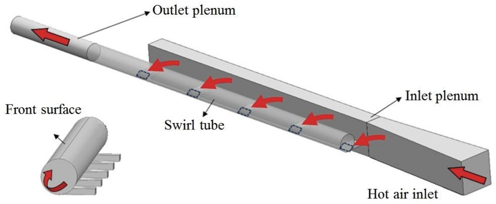
Kreith and Margolis [4] came up with the first idea of swirling air heat transfer and subsequently used it as a turbine blade cooling technology. By employing single or multiple tangential inlet jets, strong circumferential swirling flow is generated, which strengthens the turbulent mixing near the wall and significantly improves the heat transfer performance. Figure 1 shows a typical structure of the swirl hot air system that is pertinent to the aircraft wing with multiple tangential inlet jets. According to the reports of Qian et al. [5], compared with the impingement jet heat transfer, which is commonly used in the current flute tube, the swirling air could not only improve the heat transfer efficiency by 20–30% but also uniform the surface heat transfer distribution. Based on the high similarity between the turbine blade and aircraft wing structure, the swirling hot air could be a promising anti-icing technology for the applications in aircraft wings.
Previous studies on swirling air heat transfer mainly focused on the influence of structural parameters as well as flow parameters, such as the working medium, Prandtl numbers [6], jet arrangements [7,8,9],tube shapes [10,11], the Reynolds number and temperature ratio [12,13,14]. There are some representative literature papers, such as that of Rao et al. [15], who conducted Transient Liquid Crystal (TLC) experiments and Reynolds Averaged Navier–Stokes numerical simulations (RANS) on swirling air chambers with one and five tangential inlet jets. It has been shown that under equal pumping power, the five-jets swirl tube has a higher Nusselt number on the tube wall. This indicated that the swirling flow with multiple tangential jets has a better practical performance and can obtain a more uniform heat transfer distribution. Biegger et al. [16] conducted Particle Image Velocimetery (PIV) and Transient Liquid Crystal experiments to carry out an in-depth study on the swirling flow and heat transfer. They explained that the circumferential velocities with a strong gradient near the wall and the enhanced near-wall turbulence mixing are the main reasons for the high heat transfer performance. Bruschewski et al. [17] adopted the Mean Velocity Field Measurements and divided the swirling flow field into three regimes as the swirl intensity increased. Flow regime Ⅰ describes a swirling flow with a unidirectional axial velocity that occurs at a low swirl intensity, flow regime Ⅱ represents the flow with a reversed axial velocity in the swirl center and flow regime Ⅲ is characterized by three axial flow regions which are reversed in each annular region. They also paid attention to the outlet effect of the swirling tube and demonstrated that the outlet geometry is a determining parameter for flow regime Ⅲ, while flow regimes Ⅰ and Ⅱ are much less sensitive to the changes at the tube outlet. Biegger et al. [18] also carried out Detached Eddy Simulations (DES) for the single-jet swirling flow and calibrated with their experimental data. An important discovery is that the pressure loss in the swirl tube mainly comes from the strong shear forces between the high-velocity wall flow and core flow. Furthermore, Kusterer et al. [19,20] proposed a Double Swirl Chamber (DSC) configuration and showed a significant heat transfer enhancement by about 41% compared with the commonly used impingement jet heat transfer.
Previous studies have described the flow and heat transfer characteristics of the complex swirling flow in detail and revealed the flow mechanism to some extent. However, almost all of the previous studies focus on the smooth swirl tube. Few literature papers mentioned the combination of swirling flow with surface structures. In the rectangular passage channel, the surface structures, such as the rib and dimple, can significantly break the development of the thermal boundary layer and enhance the heat transfer performance [21,22,23]. For instance, the surface dimple in a straight passage channel can achieve heat transfer enhancement by 1.5–2.5 times with an increase in friction factor by 1.2–2.0 times [24]. However, the influence of surface structures on the swirl tube wall could be completely different from that in the straight rectangular channel, as the complex swirling flow is accompanied by high turbulent intensity and an additional circumferential velocity. It is of particular interest to investigate the compound heat transfer characteristics of the swirling hot air configuration combined with surface structures, which shows significance for the anti-icing applications in aircrafts. In order to obtain the complex flow and heat transfer characteristics, swirling air configurations including three to nine tangential inlet jets with four kinds of surface structures on internal wall (Trench, Rib, Dimple, Bulge) have been investigated in this paper.

2. Numerical Setups

Three-dimensional RANS-based numerical computations have been carried out with the software ANSYS FLUENT. The computational model includes two plenums to stabilize the flow fields and pressure, as shown in Figure 2. The hot air passes through the multiple tangential jet injections to form a high-intensity swirling flow in the heat transfer chamber, and it is eventually discharged by the outlet, as shown by the arrows in Figure 2. The boundary condition of the inlet is the velocity inlet, with an air temperature of 323.15 K, and the outlet is the pressure outlet, with a relative pressure of 0 Pa. The swirl tube wall has a constant temperature of 293.15 K, while the other walls are non-slip and adiabatic. According to the previous paper [15,17], the investigated swirling flow is within the scope of regime Ⅱ; therefore, the present outlet geometry has little influence on the upstream flow field, and the heat transfer performance is barely affected by the shape of the tube outlet [16].
In this paper, five Reynolds numbers from 10,000 to 50,000 based on the tube diameter are investigated and defined as Equation (1). The wall heat transfer is characterized by the Nusselt number, which is expressed in Equation (2). Note that the tube surface is divided into two parts from the front to the rear, and as the external icing region only corresponds to the front surface of the tube wall, only the heat transfer coefficient on the front surface wall is taken into account for the averaged Nusselt number.
R e D = ρ u D D / μ ,
N u = h f D / λ = q D / ( T w T j ) / λ ,
The swirling anti-icing chamber has a diameter D = 50 mm and a total length of L = 20D. The flow and heat transfer characteristics in the swirl tube induced by a single tangential jet and multiple tangential jets could be obviously different [15], and, thus, the jet number N and jet spacing LJ are of much importance in this investigation. The present swirling air configuration includes three to nine tangential inlet jets, with the jet spacing ratio L/D decreasing from 0.8 to 0.2. Note that all the inlet jets have a rectangular shape (W × H), and the detailed dimensional and non-dimensional parameters of the swirling heat transfer chamber are shown in Table 1.
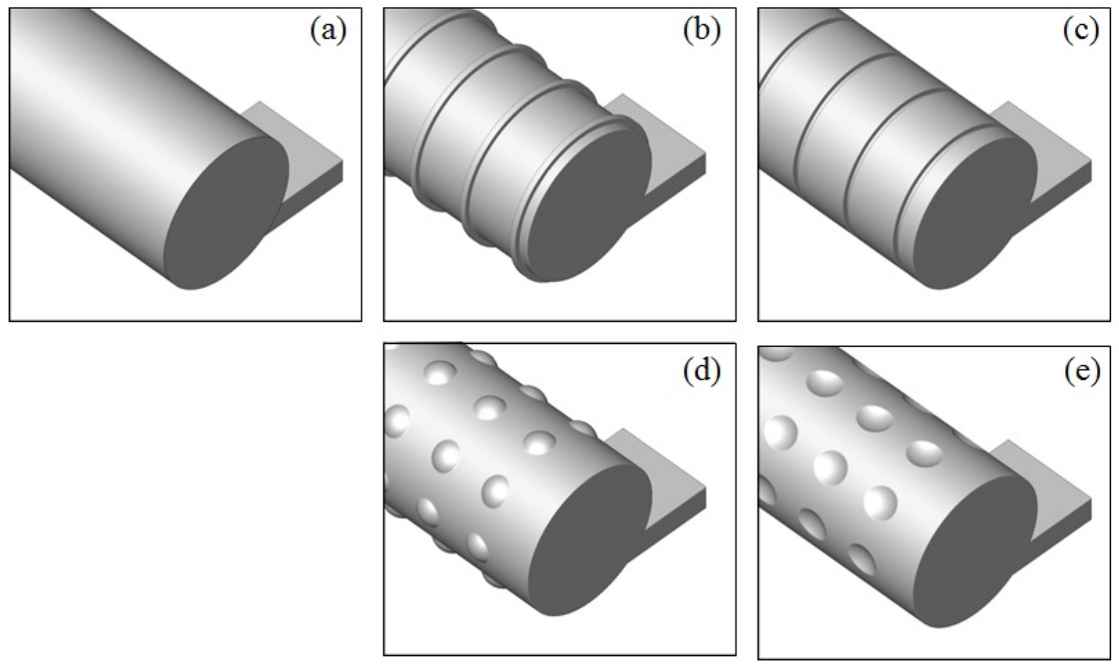
Different surface structures with a typical geometrical size and arrangement [21] are placed on the swirl chamber internal wall to explore the compound heat transfer characteristics. The influence of surface structures on the heat transfer in the swirl tube could be completely different from that in the straight rectangular channel, as the complex swirling flow is accompanied by high turbulent intensity and a thin boundary layer. The four kinds of surface structures are the trenches, ribs, dimples, and bulges, as shown in Figure 3, all of which have the same depth/height of 0.002 m and the same spacing of 0.02 m in the X direction. In every row of the dimple or bulge, there are eight structure units with a layout angle of 0°, 45°, 90°, 135°, 180°, 225°, 270° and 315°. There are 5/10/20 rows of structures between two tangential jets for the configurations with 9/5/3 inlet jets. As such, the surface structures are considered to be placed pretty densely on the swirling tube internal wall.
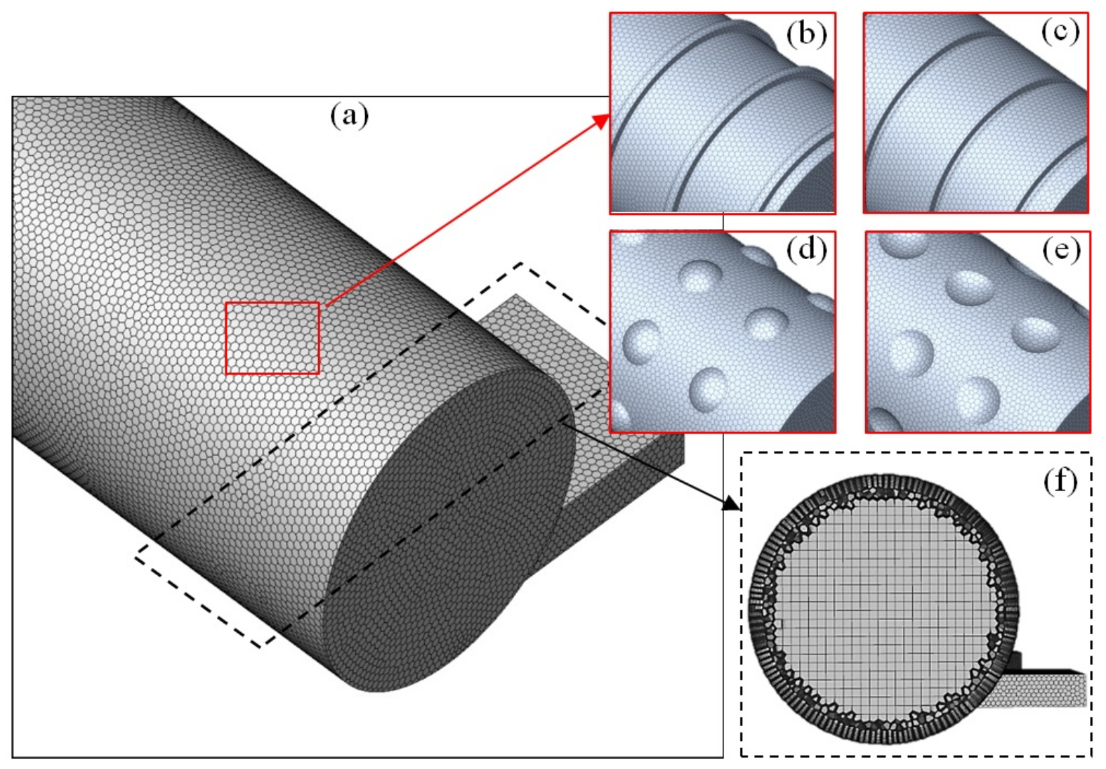
The software FLUENT MESHING has been used to generate hybrid meshes for the numerical computations. The mesh system includes structural elements in the core region, polyhedral layers in the near-wall region and an octree grid placed to connect the above regions, as shown in Figure 4. As the simulation adopts the SST k ω two-equation turbulence model, which is suitable for a high-intensity swirling flow [25], the height of the first near-wall node is highly required for the calculation. Therefore, more than 15 prism layers are set near the wall with a non-dimensional distance number, y+, that is to be less than 2, and this meets the requirements of the SST k ω turbulence model. Furthermore, the generated meshes show good adaptability to the SIMPLE C algorithm and PRESTO scheme used in this study for pressure–velocity coupling and pressure term spatial discretization. After more than 4000 iterations, the momentum and energy residual are reduced to 1 × 10⁻⁴ and 1 × 10⁻⁷, the computed physical values changed by less than 0.05% and the computations are considered to be converged.
To find a proper mesh density, a grid independence check has been conducted. Three sets of meshes are used to calculate the heat transfer on the smooth swirling tube, and the node numbers are 2.0 million, 3.0 million and 4.5 million. At a tube Reynolds number of 40,000, the computed Nusselt numbers on the tube’s internal wall are 151.8, 151.0 and 150.8, respectively. After the node number exceeds 3.0 million, the change in the heat transfer is less than 1%, indicating that the 3.0 million nodes are sufficient for the simulations and are thus adopted in this study.

3. Data Validations

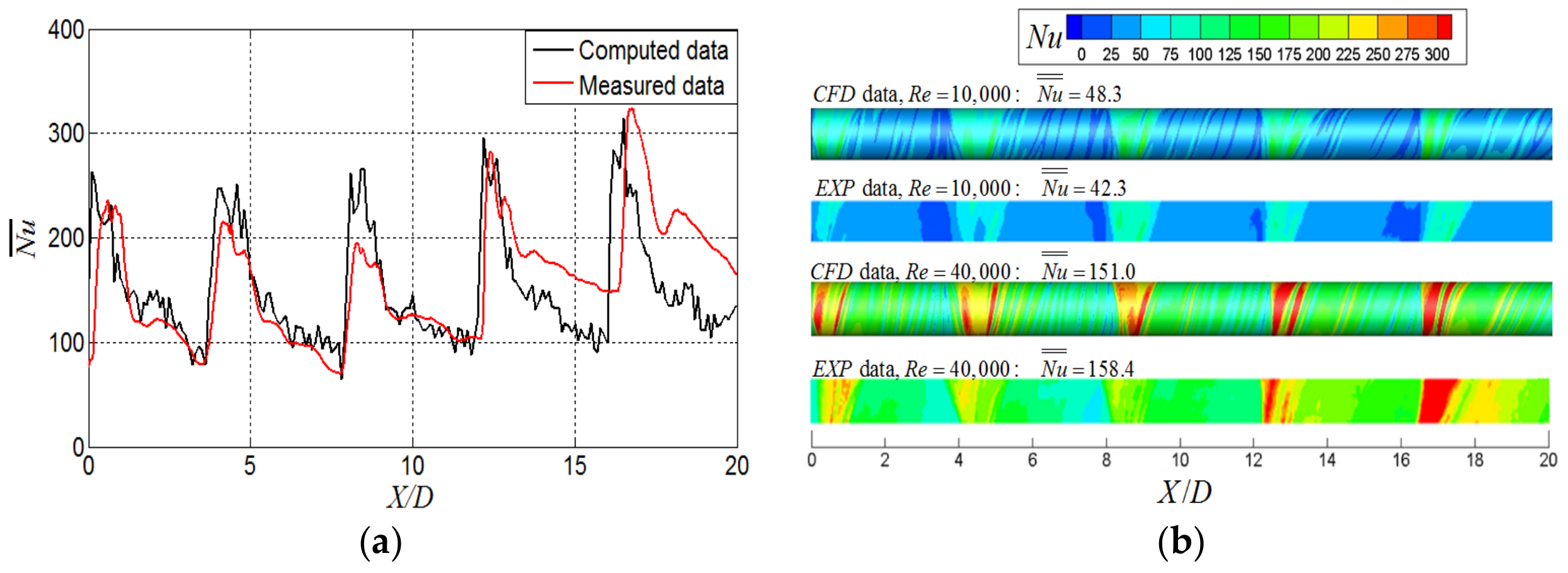
Detailed comparisons with the literature data have been made to validate the numerical method. Figure 5 shows the validations with the experimental data from Rao et al. [15], where a transient thermochromic liquid crystal experimental method has been used to obtain the high-resolution Nusselt number on the front surface of the tube wall. Figure 5 presents the comparisons of the circumferentially averaged Nusselt number and the local Nusselt number distribution for the smooth tube at ReD = 40,000. It can be seen that the heat transfer distributions are in a good agreement with each other, and the averaged Nusselt number deviates within 4.7–14.2%. As shown in Table 2, a higher deviation exists at a lower Reynolds number, but the deviation is within only ±5 percent when the Reynolds number exceeds 20,000. Due to the complexity of the swirling flow, the simulation results are considered reasonably acceptable and reliable. The deviation between the numerical computed data and the experimental measured data mainly comes from the slight difference in the mass flow distribution in jets, especially when the mass flow rate is relatively small at ReD = 10,000. The limitations of the turbulence model simulating the complex swirling flow also contribute to the deviation between the measured data and the computed data.

4. Results and Discussions

This paper evaluates the swirling hot air anti-icing performance from the Nusselt number, total heat transfer quantity and pressure loss characteristics and reveals relevant flow fields by the circumferential velocity as well as the swirl intensity.

4.1. Influence of Jet Numbers

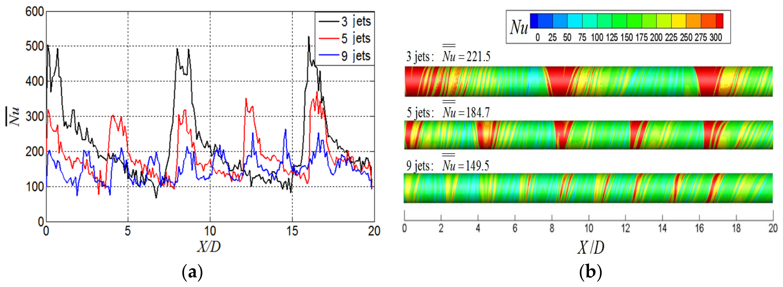
The number and spacing of tangential inlet jets have a significant influence on the heat transfer of swirling air and change the effect of surface structures on the tube wall, which needs to be carefully examined. Figure 6 presents the circumferentially averaged Nusselt number and local Nusselt number distribution with different jet numbers and at equal tube Reynolds numbers, where the mass flow rate is also identical. It can be seen that the Nusselt number reaches the highest point around jet stagnations, decaying downstream along the X direction and increasing again when the next jet is injected. The three-jet configuration has the highest Nusselt number in jet stagnations and has the largest jet spacing, which indicates that the high heat transfer decreases in a greater distance between two neighboring jet stagnations. For example, with three jets arranged on the tube wall, the circumferentially averaged Nusselt number decays rapidly from more than 500 to less than 100 at ReD = 50,000, resulting in a very uneven heat transfer distribution along the tube length. As the jet number increases, the area-averaged Nusselt number decreases, and the heat transfer uniformity is improved significantly. Correspondingly, with nine inlet jets arranged on the tube wall, the difference in the circumferentially averaged Nusselt number under a single jet is reduced to about 100 at ReD = 50,000.

4.2. Heat Transfer Characteristics with Surface Structures

Figure 7 compares the effect of various surface structures on the swirl tube wall with nine jets at ReD = 50,000. As the swirling flow develops along the tube, the turbulence intensity is pretty high and the boundary layer is quite thin, and the effect of the surface structure is complex. On one hand, the surface structure further enhances the turbulence intensity and improves the local Nusselt number. On the other hand, the development of swirling flow is hindered by the placement of the surface structure, leading to heat transfer deterioration between the two jets. As such, the above-mentioned two opposite effects jointly determine the influence of surface structures on the swirling air heat transfer. Compared with the smooth swirl tube, the trenches and ribs fail to achieve a higher Nusselt number, as the adverse effects of the surface structure outweigh the beneficial ones. Since the trenches and ribs have a relatively weak enhancement on the near-wall turbulent kinetic energy along the circumference direction, the local Nusselt number enhancement that benefited from the increase in the local turbulence intensity is less than the Nusselt number reduction caused by the hindering effect of the surface structures on the swirling flow. Instead, the dimples and bulges have relatively less resistance to the swirling flow and can significantly induce the complex vortex and improve near-wall turbulence intensity. The enhancement of the local Nusselt number overcomes the adverse effect for hindering the swirling flow. A closer look in Figure 7 reveals that the Nusselt number in the trailing edge of dimples and the leading edge of bulges is much improved, which greatly contributes to the overall heat transfer improvements. From the overall point of view, the surface dimples and bulges are conducive to improving the swirling Nusselt number. However, placing surface trenches and ribs on the wall shows Nusselt number deterioration relative to the smooth swirl tube.
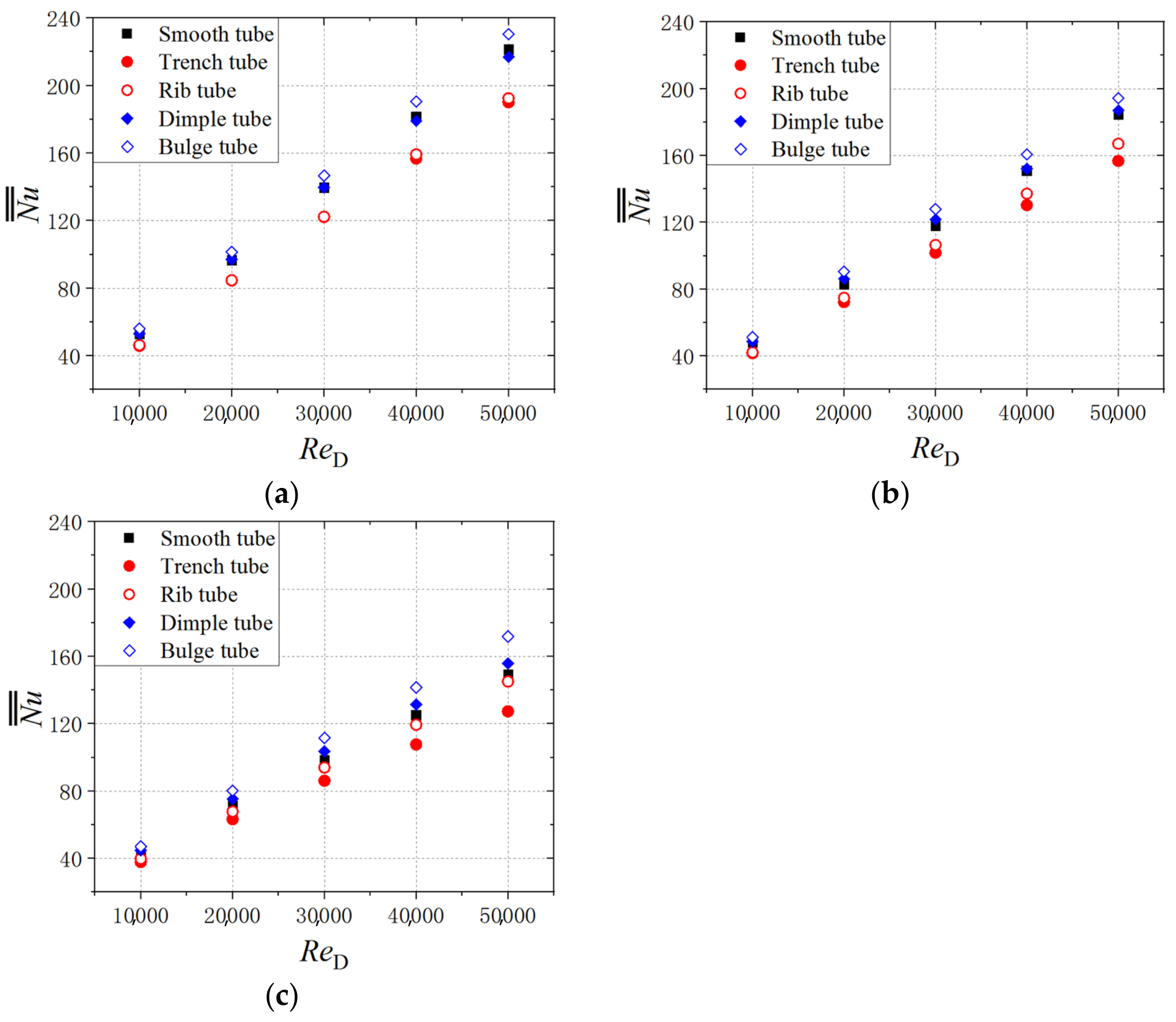
All the swirling air configurations keep the Nusselt number increasing with the Reynolds number. At the same Reynolds number, the bulge tube has the highest heat transfer performance, and the trench tube performs worst. Figure 8 provides the comparisons of the area-averaged Nusselt number with the jet number increasing from three to nine and the jet spacing ratio decreasing from 0.8 to 0.2. The jet number and spacing have an obvious influence on the effect of the surface structure, which is closely relative to the development of swirling flow. With surface structures placed on the tube wall, the longer the jet spacing is, the worse the heat transfer deterioration will be in the downstream, as the flow is continuously hindered. As such, the configuration with a smaller jet spacing usually achieves a higher Nusselt number enhancement with surface structures placed on the wall. Table 3 summarizes the changes in the area-averaged Nusselt number for the structured swirl tube compared with the smooth swirl tube at ReD = 50,000. Quantitatively, the bulge tube can achieve a +4.0% to +15.0% higher averaged Nusselt number as the jet increases from 3 to 9. The dimple tube changes the Nusselt number by −2.2% to +4.3%, the rib tube decreases the Nusselt number by −13.1% to −2.9%. Moreover, the trench tube reduces the Nusselt number the most, which ranges from −15.1% to −14.2% and is less affected by the jet number. It is noteworthy that, with the placement of trenches, ribs, dimples and bulges, the heat transfer areas are also increased by about +21.6%, +18.4%, +3.9% and +2.3%, respectively. The total heat transfer quantity enhancements should add this part and are estimated to be +7.3%, +15.5%, +8.2% and +17.3% with nine jets at ReD = 50,000 compared with the smooth swirl tube.

4.3. Pressure Loss Characteristics with Surface Structures

For the smooth swirl tube, the pressure loss between the inlet and outlet mainly comes from the strong shear forces between the high-velocity wall flow and the core flow [18]. Here, with the placement of surface structures, a significant pressure loss also comes from the near-wall region as the near-wall swirling flow interacts with the surface structures. These two parts of pressure losses jointly determine the pressure loss characteristics in the structured swirl tube. Placing surface structures on the wall reduces the swirling intensity in the tube, and the shear force-induced pressure loss is lowered by the surface structures compared with the smooth tube. In the near-wall region, the trenches and ribs strongly interact with the swirling flow and result in a significantly higher near-wall pressure loss. On the contrary, the dimples and bulges show less resistance to the swirling flow, and the near-wall pressure loss is relatively small. Comprehensively, the surface trenches, dimples and bulges are conducive to lowering the pressure loss in the swirling air configuration. However, placing surface ribs on the wall shows increased pressure losses relative to the smooth swirl tube.
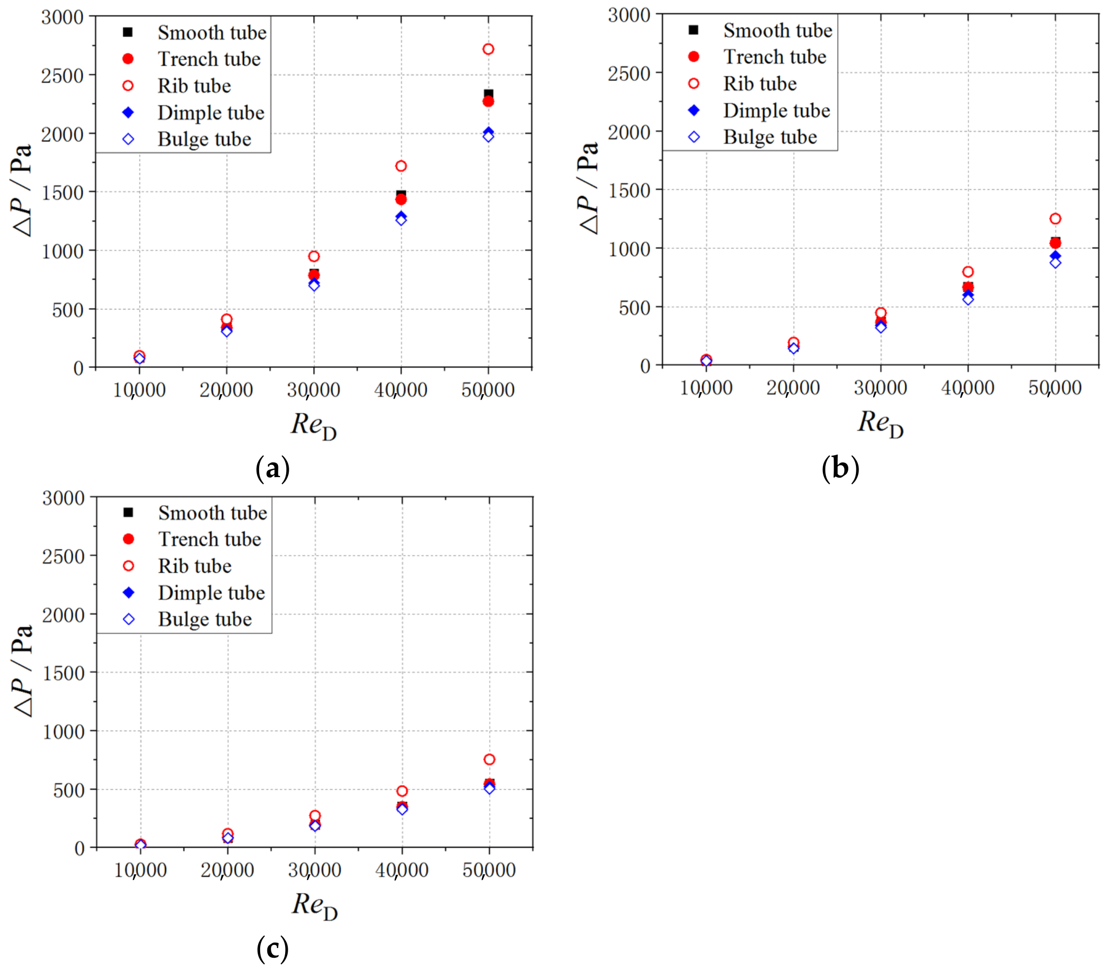
The pressure loss in the swirling air configuration increases with the Reynolds number, while at the same Reynolds number, the rib tube shows the highest pressure loss values, and the bulge tube has the lowest values. Figure 9 presents the pressure loss information with various surface structures and with the jet number increasing from three to nine. It can be seen that the jet number and spacing greatly influence the effect of surface structures on the pressure loss characteristics. The higher the jet number is, the smaller the reduction in the pressure loss caused by the trenches, dimples and bulges will be and the greater the pressure loss augmentation led by the ribs will be. Quantitatively, as shown in Table 4, the bulge can achieve −15.6% to −8.6% pressure loss reductions as the jet number increases from three to nine. The dimple tube changes the pressure loss by −13.9% to −5.6%, the rib tube increases the pressure loss by +16.4% to +36.9%. Moreover, the pressure loss with the trench tube is close to that of the smooth tube, which changes by −2.7% to −1.4% and is less affected by the jet number. Considering both heat transfer and pressure loss, the surface bulge tube is the one that performs the best among the four investigated surface structures, and it shows the highest enhancement performance in the flow environment coupled with a high turbulence swirling flow.

4.4. Swirl Intensity

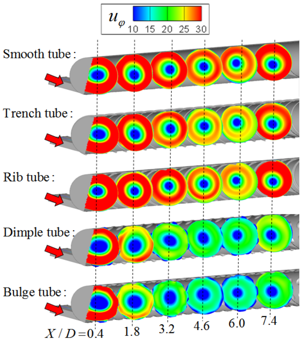
To reveal the effect of surface structures on the flow field, which is closely related to the heat transfer and pressure loss characteristics, Figure 10 shows the circumferential velocity distributions on various cross sections at ReD = 50,000 and with three jets. It can be seen that a pretty high circumferential velocity is formed after the first tangential jet, while the swirling flow shrinks towards the tube core, leading to the decreased circumferential velocity in the downstream. Since the flow revolves around the tube center, the core region has a very low circumferential velocity. By placing trenches and ribs on the wall, the circumferential velocity distribution shows little change compared with the smooth tube. The dimples and bulges could significantly suppress the high-circumferential-velocity regions and therefore lower the shear force between the wall flow and core flow. This explains why the dimples and bulges are conducive to reducing the pressure loss in the swirling air configuration.
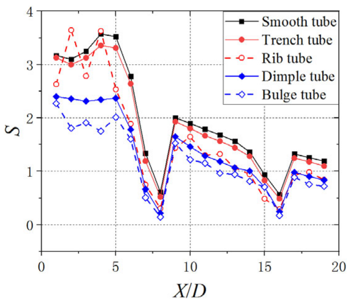
A non-dimensional swirl number S is introduced to describe the strength of the swirling flow, as described in Equation (3) and shown in Figure 11. Here, I φ and I x are the averaged angular and axial momentum in different cross sections. Consistent with the circumferential velocity, the swirl number decreases from upstream to downstream after each jet injection. The placement of trenches and ribs lowers the swirl number along the tube to some extent, but a more obvious reduction in the swirl number can be seen with the dimples and bulges arranged on the tube wall. Quantitatively, the surface trenches, ribs, dimples and bulges reduce the swirl number by 5.7%, 20.3%, 30.2% and 40.8%, respectively, at ReD = 50,000 with three jets. The circumferential velocity and swirl number provide information on the flow fields in swirling air configurations with surface structures on the wall and reveal relevant interaction mechanisms between the swirling flow and surface structures.
S = I φ R I X = r = 0 R ρ u X u φ 2 π r 2 d r R r = 0 R ρ u X 2 2 π r d r = 2 A u X u φ r d A D A u X 2 d A ,

5. Summary and Conclusions

In this paper, a series of numerical computations have been carried out to investigate the heat transfer and pressure loss characteristics of swirling air anti-icing systems with various surface structures arranged on the tube’s internal wall. The results were obtained by the SST k ω turbulence model, and careful validations have been conducted between the numerical and experimental data, which show acceptable and reliable computational accuracy. Within the tube Reynolds number from 10,000 to 50,000, the main conclusions are listed as follows:
(1)
The number and spacing of the tangential inlet jet have a significant influence on the heat transfer performance of the swirling flow. As the jet number increases from three to nine, the averaged Nusselt number decreases, and the heat transfer uniformity is obviously improved.
(2)
The surface dimples and bulges are conducive to improving the Nusselt number on the swirl tube wall; however, placing trenches and ribs shows Nusselt number deterioration relative to the smooth swirl tube. With a smaller jet spacing and more jet injections, the effect of surface structures tends to be more positive.
(3)
Correspondingly, the surface trenches, dimples and bulges cause reductions in the pressure loss, while the surface ribs lead to a pressure loss increment. The higher the jet number is, the smaller the reduction in the pressure loss caused by the trenches, dimples and bulges will be and the greater the pressure loss augmentation led by the ribs will be.
(4)
Among the four investigated surface structures, the surface bulge is the one with the best heat transfer and pressure loss performance in the swirling air anti-icing configuration. The surface bulge could enhance the averaged Nusselt number by 4.0–15.0%, increase the total heat transfer quantity by up to 17.3% and reduce the hot air pressure loss by 8.6–15.6%. This shows significance for improving the performance and efficiency of the hot air anti-icing system.
(5)
The circumferential velocity and swirl number are introduced to describe the flow fields and reveal the flow mechanism. The trenches and ribs have little influence on the circumferential velocity distribution and lead to less of a reduction in the swirl intensity. However, the surface dimples and bulges significantly suppress the swirl intensity by up to about 40.8%.

Author Contributions

Conceptualization, Y.L. (Yuyang Liu) and S.L.; Data curation, X.D.; Formal analysis, Y.L. (Yuyang Liu); Funding acquisition, X.Y.; Investigation, Y.L. (Yuyang Liu); Methodology, Y.L. (Yuyang Liu); Project administration, X.Y.; Software, S.L. and X.Y.; Supervision, X.Y.; Validation, Y.L. (Yong Luan) and Y.R.; Visualization, X.D.; Writing—original draft, Y.L. (Yuyang Liu); Writing—review & editing, Y.L. (Yong Luan). All authors have read and agreed to the published version of the manuscript.

Funding

This research and APC were funded by the National Science and Technology Major Project (No. J2019-Ⅲ-0010-0054).

Data Availability Statement

Data will be provided on request.

Conflicts of Interest

The authors declare no financial or personal relationships with other people or organizations which can inappropriately influence the work. The authors do not have any commercial or associative interests that represent a conflict of interest in connection with this paper.

References

  1. European Aeronautics. A Vision for 2020, Report of the Group of Personalities; European Aeronautics: Stockholm, Sweden, 2001. [Google Scholar]
  2. Steering Committee for the Decadal Survey of Civil Aeronautics. Decadal Survey of Civil Aeronautics: Foundation for the Future; The National Academics Press: Washington, DC, USA, 2006. [Google Scholar]
  3. Heinrich, A.; Ross, R.; Zumwalt, G.; Provorse, J.; Padmanabhan, V. Aircraft Icing Handbook Volume 1, AD-A238039; Department of Transportation Federal Aviation Administration: Washington, DC, USA, 1991. [Google Scholar]
  4. Kreith, F.; Margolis, D. Heat transfer and friction in turbulent vortex flow. Appl. Sci. Res. 1959, 8, 457–473. [Google Scholar] [CrossRef]
  5. Qian, C.; Flannery, K.; Saito, K.; Downs, J.P.; Soechting, F.O. Innovative vortex cooling concept and its application to turbine airfoil trailing edge cooling design. In Proceedings of the 33rd Joint Propulsion Conference and Exhibit, Seattle, WA, USA, 6–9 July 1997. Paper No. 97-3013. [Google Scholar]
  6. Blum, H.A.; Oliver, L.R. Heat transfer in a decaying vortex system. ASME 1966. ASME Paper GT1966-WA/HT-62. [Google Scholar]
  7. Chang, F.; Dhir, V.K. Turbulent flow field in tangentially injected swirl flows in tubes. Int. J. Heat Fluid Flow 1994, 15, 346–356. [Google Scholar] [CrossRef]
  8. Du, C.H.; Li, L.; Wu, X. Effect of jet nozzle geometry on flow and heat transfer performance of vortex cooling for gas turbine blade leading edge. Appl. Therm. Eng. 2016, 93, 1020–1032. [Google Scholar] [CrossRef]
  9. Du, C.H.; Li, L.; Chen, X.X. Numerical study on effects of jet nozzle angle and number on vortex cooling behavior for gas turbine blade leading edge. ASME 2016. ASME Paper GT2016-57390. [Google Scholar]
  10. Mousavi, S.M.; Ghadimi, B.; Kowsary, F. Numerical study on the effects of multiple inlet slot configurations on swirl cooling of a gas turbine blade leading edge. Int. Commun. Heat Mass Transf. 2018, 90, 34–43. [Google Scholar] [CrossRef]
  11. Hwang, J.J.; Cheng, C.S. Augmented heat transfer in a triangular duct by using multiple swirling jets. J. Heat Transf. 1999, 121, 683–690. [Google Scholar] [CrossRef]
  12. Hay, N.; West, P.D. Heat transfer in free swirling flow in a pipe. Int. J. Heat Transf. 1975, 97, 411–416. [Google Scholar] [CrossRef]
  13. Glezer, B.; Moon, H.K.; Kerrebrock, J.; Bons, J.; Guenette, G. Heat transfer in a rotating radial channel with swirling internal flow. ASME 1998. ASME Paper 98-GT-214. [Google Scholar]
  14. Hedlund, C.R.; Ligrani, P.M.; Moon, H.K.; Glezer, B. Heat transfer and flow phenomena in a swirl chamber simulating turbine blade internal cooling. ASME J. Turbomach. 1999, 121, 804–813. [Google Scholar] [CrossRef]
  15. Rao, Y.; Biegger, C.; Weigand, B. Heat transfer and pressure loss in swirl tubes with one and multiple tangential jets pertinent to as turbine internal cooling. Int. J. Heat Mass Transf. 2017, 106, 1356–1367. [Google Scholar] [CrossRef]
  16. Biegger, C.; Weigand, B. Flow and heat transfer measurements in a swirl chamber with different outlet geometries. Exp. Fluids 2015, 56, 78–88. [Google Scholar] [CrossRef]
  17. Bruschewski, M.; Grundmann, S.; Schiffer, H.P. Considerations for the design of swirl chambers for the cyclone cooling of turbine blades and for other applications with high swirl intensity. Int. J. Heat Fluid Flow 2020, 86, 108670. [Google Scholar] [CrossRef]
  18. Biegger, C.; Sotgiu, C.; Weigand, B. Numerical investigation of flow and heat transfer in a swirl tube. Int. J. Therm. Sci. 2015, 96, 319–330. [Google Scholar] [CrossRef]
  19. Kusterer, K.; Lin, G.; Bohn, D.; Sugimoto, T.; Tanaka, R.; Kazari, M. Heat transfer enhancement for gas turbine internal cooling by application of double swirl cooling chambers. ASME 2013. ASME Paper GT2013-94774. [Google Scholar]
  20. Kusterer, K.; Lin, G.; Sugimoto, T.; Bohn, D.; Tanaka, R.; Kazari, M. Novel gas turbine blade leading edge cooling configuration using advanced double swirl chambers. ASME 2015. ASME Paper GT2015-42400. [Google Scholar]
  21. Liu, G.W.; Zhang, L.; Guo, T. A review of heat transfer enhancement with dimpled surface. J. Aerosp. Power 2007, 22, 1785–1791. [Google Scholar]
  22. Rao, Y.; Zhang, P.; Xu, Y.M. Experimental study and numerical analysis of heat transfer enhancement and turbulent flow over shallowly dimpled channel surfaces. Int. J. Heat Mass Transf. 2020, 160, 120195. [Google Scholar] [CrossRef]
  23. Rao, Y.; Zhang, P. Experimental Study of Heat Transfer and Pressure Loss in Channels with Miniature V Rib-Dimple Hybrid Structure. Heat Transf. Eng. 2019, 38, 1–11. [Google Scholar] [CrossRef] [Green Version]
  24. Burgess, N.K.; Ligrani, P.M. Effects of dimple depth on channel Nusselt numbers and friction factors. ASME J. Heat Transf. 2006, 127, 839–847. [Google Scholar] [CrossRef]
  25. Launder, B.E.; Spalding, D.B. The Numerical Computation of Turbulent Flows. Comput. Methods Appl. Mech. Eng. 1974, 3, 269–289. [Google Scholar] [CrossRef]
Figure 1. Schematic of swirling hot air anti-icing technology for aircraft wings.
Energies 16 01179 g001
Figure 2. Computational model of swirling hot air anti-icing configuration.
Energies 16 01179 g002
Figure 3. Swirl tube with surface structures on the internal wall: (a) Smooth tube; (b) Trench tube; (c) Rib tube; (d) Dimple tube; (e) Bulge tube.
Energies 16 01179 g003
Figure 4. Schematics of the mesh for computations: (a) Smooth tube; (b) Trench tube; (c) Rib tube; (d) Dimple tube; (e) Bulge tube; (f) Cross section.
Energies 16 01179 g004
Figure 5. Validation between the current computed data and the experimental measured data from Rao et al. [15] for the smooth tube with five jets: (a) Circumferentially averaged Nusselt number at ReD = 40,000; (b) Local Nusselt number distributions at ReD = 10,000 and ReD = 40,000.
Energies 16 01179 g005
Figure 6. Influence of the jet number on the Nusselt number distribution of a smooth tube at ReD = 50,000: (a) Circumferentially averaged Nusselt number; (b) Local Nusselt number.
Energies 16 01179 g006
Figure 7. Comparisons of the local Nusselt number with different surface structures on the swirl tube wall with nine jets at ReD = 50,000.
Energies 16 01179 g007
Figure 8. Comparisons of the area-averaged Nusselt number on the smooth tube and the structured tube at different ReD values: (a) three jets; (b) five jets; (c) nine jets.
Energies 16 01179 g008
Figure 9. Comparisons of the pressure loss between the inlet and outlet with various surface structures at different ReD values: (a) three jets; (b) five jets; (c) nine jets.
Energies 16 01179 g009
Figure 10. Circumferential velocity distributions on several cross sections in the swirl tube with various surface structures at ReD = 50,000 with three jets.
Energies 16 01179 g010
Figure 11. Local swirl number on different cross sections in the swirl tube with various surface structures at ReD = 50,000 with three jets.
Energies 16 01179 g011
Table 1. Dimensional and non-dimensional parameters of swirling air configurations.
ParameterValueParameterValue
N3, 5, 9ReD10,000–50,000
L1.0 mL/D20.0
D0.05 mLJ/D0.2–0.8
W0.0333 mW/D0.67
H0.0085 mH/D0.17
Table 2. Comparisons of the area-averaged Nusselt number between the current computed data and the experimental measured data from Rao et al. [15] for a smooth tube with five jets.
ReDCFD Data of NuEXP Data of NuDeviations
10,00048.342.3+14.2%
20,00083.282.0+1.5%
30,000118.0122.5−3.7%
40,000151.0158.4−4.7%
Table 3. Area-averaged Nusselt number for a structured tube compared with a smooth tube with different jets at ReD = 50,000.
3 Jets5 Jets9 Jets
Trench tube−14.2%−15.1%−14.7%
Rib tube−13.1%−9.5%−2.9%
Dimple tube−2.2%+1.3%+4.3%
Bulge tube+4.0%+5.3%+15.0%
Table 4. Pressure loss for the structured tube compared with the smooth tube with different jets at ReD = 50,000.
3 Jets5 Jets9 Jets
Trench tube−2.7%−1.3%−1.4%
Rib tube+16.4%+18.4%+36.9%
Dimple tube−13.9%−11.7%−5.6%
Bulge tube−15.6%−17.1%−8.6%
Disclaimer/Publisher’s Note: The statements, opinions and data contained in all publications are solely those of the individual author(s) and contributor(s) and not of MDPI and/or the editor(s). MDPI and/or the editor(s) disclaim responsibility for any injury to people or property resulting from any ideas, methods, instructions or products referred to in the content.