Article

Impact of Injection Gas on Low-Tension Foam Process for EOR in Low-Permeability Oil-Wet Carbonates

Hildebrand Department of Petroleum and Geosystems Engineering, The University of Texas at Austin, Austin, TX 78712, USA
*
Author to whom correspondence should be addressed.
Energies 2023, 16(24), 8021; https://doi.org/10.3390/en16248021
Submission received: 13 November 2023 / Revised: 6 December 2023 / Accepted: 8 December 2023 / Published: 12 December 2023
(This article belongs to the Section H1: Petroleum Engineering)

Abstract

:
Low-tension gas (LTG) flooding has been proven in lab-scale experiments to be a viable tertiary enhanced oil recovery (EOR) technique in low-permeability (~10 mD) oil-wet carbonates. Work carried out previously almost exclusively focused on water-wet cores. The application of LTG in oil-wet carbonates is investigated in this study along with the impact of a hydrocarbon (HC) mixture as the injection gas on oil–water microemulsion phase behavior. The optimum injection gas fraction (ratio of gas injection rate to total injection rate of gas and water) for the hydrocarbon gas mixture in oil-wet carbonates regarding the oil recovery rate was determined to be 60% as it resulted in around 50% residual oil in place (ROIP) recovery. It was shown that proper mobility control can be achieved under these conditions even in the absence of strong foam. The effect of HC gas dissolution in oil was clearly shown by replacing the injection HC gas with nitrogen under the same conditions. Furthermore, the importance of ultra-low interfacial tension (IFT) produced by the injection gas and surfactant slug is proven by comparing injection at sub-optimum salinity to injection at optimum salinity.

1. Introduction

After producing oil from a reservoir under natural drive mechanisms, some residual oil remains trapped, and secondary oil recovery techniques must be employed. Even after that, a relatively significant amount of oil is left behind in the reservoir [1]. A number of enhanced oil recovery (EOR) methods can be implemented to produce as much of the residual oil as possible. Chemical EOR relies on the use of chemicals with or without an injection gas to increase oil recovery when common methods such as waterflooding or immiscible gas flooding have run their course. Traditional chemical EOR techniques include polymer floods, surfactant–polymer (SP) floods, and alkali–surfactant–polymer (ASP) floods [2,3]. Polymer floods are specifically designed to improve sweep efficiency via mobility ratio reduction, with the mobility ratio being defined as the ratio of displacing fluid mobility to that of the displaced fluid mobility. It involves the injection of a high-viscosity polymer slug, followed by a water chase. The mobilized oil–polymer mobility ratio is indeed favorable; however, the polymer–chase water mobility ratio is not, leading to water fingering. This necessitates having a buffer zone between the polymer and the chase water with a gradually decreasing concentration of the polymer [4]. SP floods utilize amphiphilic molecules that reduce oil–water interfacial tension (IFT), which promotes trapped oil displacement. ASP flooding relies on the same mechanism of oil production, with a notable reduction in surfactant adsorption on formation minerals with the addition of an alkali [5]. However, these types of floods are not universally applicable when taking into account unfavorable reservoir conditions (high temperature, high salinity, low permeability) and both economic and environmental considerations.
The recent increase in environmental concerns makes it difficult to continue with practices such as gas flaring, making it necessary to find an alternative use to the produced field gas. One viable option is to reinject the produced hydrocarbon gas into the reservoir. Gas flooding is well developed and has been successfully employed in carbonate reservoirs in the United States and elsewhere [6,7]. Coreflood experiments have shown that WAG flooding using flue gas consisting mainly of N2 and CO2 can not only increase oil recovery but also increase gas storage capacity [8]. Furthermore, novel numerical models are being developed specifically for fractured underground gas storage in depleted oil and gas reservoirs [9]. The success of this EOR method is dependent on the reservoir pressure being at or above the minimum miscibility pressure to achieve miscible oil displacement. This allows the mass transfer of intermediate components from the flowing gas to the oil, as well as oil swelling and viscosity reduction [10]. It is apparent that reservoirs that are depleted through primary and/or secondary recovery are not suitable candidates for the gas EOR method, given their lower pressure. However, if the hydrocarbon gas is injected along with a surfactant solution, partial miscibility can be achieved between the injected solution and the resident oil phase. The injection of a combination of gas and surfactant to produce residual oil is known as low-tension gas (LTG) flooding.
LTG flooding works by achieving ultra-low interfacial tension, less than 10−3 mN/m, through the use of a surfactant solution, which creates a more mobile oil–water microemulsion phase when it contacts the resident oil. This solution also has good foaming ability with the injected gas, which plays a vital role in mobility control, leading to better sweep efficiency. This injection technique leads to a favorable mobility ratio between the now mobilized oil and the in situ generated foam [11].
Foam generated by alkali–surfactant–gas (ASG) floods was determined to have an advantage over polymer floods in high-permeability sand packs very early on [12]. Experiments using 450–500 millidarcy (mD) sandstone cores also showed that the performance of alternating slugs of gas and surfactant solution is comparable to polymer floods [13]. Using gas as an alternative to polymer in alkali–surfactant floods was shown to be successful in dolomite cores (2–447 mD) where oil recovery reached 87% residual oil in place (ROIP). Effluent salinity data indicated that there was no breakthrough of the injected slug before 1 pore volume (PV) of injection, confirming the lack of fingering/channeling and proper mobility control [14]. Several high-performance surfactant–gas corefloods with core samples of low-to-medium permeability were conducted to focus specifically on the effectiveness of gas as a mobility control agent in chemical EOR [15]. It was successfully shown from pressure drop data and oil recovery, which was consistently above 75% ROIP, that gas injection does indeed provide favorable mobility control. The pressure drop data were also shown to be within the practical operational limit in the field.
The efficiency of surfactant–gas floods was demonstrated with both methane and nitrogen gas under harsh salinity (~230 g/L) and high temperature (above 80 °C) in sub-100 mD carbonate cores, where 80% oil recovery was achieved [16].
Polymers commonly used in field-scale SP floods would not be effective in such conditions as they would not be stable and degrade, losing their viscosity [17]. Additional studies have been conducted, asserting that the use of surfactants, both co-injected and alternating with gas, improves mobility control and increases oil recovery of gas floods [18,19]. Successful LTG floods were carried out in low-permeability carbonates (<10 mD) at high temperature (69 °C) and salinity (214,000 ppm TDS), where nitrogen was co-injected with a surfactant solution to achieve more than 80% ROIP for both secondary and tertiary recovery [20,21]. Although IFT reduction comes mainly from the surfactant, there is some contribution coming from the added divalent cations in the brine. Experiments changing the composition of ion-engineered smart water have shown that decreasing the concentration of monovalent cations such as potassium K+ and sodium Na+ and increasing divalent cation concentration such as calcium Ca2+ and magnesium Mg2+ led to a decrease in oil–water IFT [22].
All LTG floods mentioned so far have been conducted using nitrogen as the injected gas, with the cores being water wet. It was recently shown that LTG can be a feasible injection strategy in 80–200 mD fractured, oil-wet carbonate cores at high temperature (above 80 °C) and ultra-high salinity (more than 23% TDS), where a 50% incremental oil recovery was achieved as compared to waterflooding [23]. Seeing how the creation of microemulsions and foam generation for mobility control are the two key mechanisms through which LTG increases oil recovery, it is necessary to determine the impact of both the injection gas and rock wettability on the microemulsion phase behavior and foam strength. It was recently determined that for conditions of 69 °C and 1500 psi, there was no significant change in the solubilization ratio when switching from nitrogen gas to methane. However, the presence of ethane did have an effect of decreasing the optimal Type III microemulsion salinity or increasing the solubilization ratio [24]. Preliminary investigations in aged carbonates (~10 mD) in the presence of high-salinity brine (179,000 ppm TDS) showed that LTG as a tertiary recovery technique can achieve up to 40% ROIP recovery within 1 PV of total fluid injection and is more viable than traditional WAG or foam floods [25]. The work presented here builds on those results and aims to better understand LTG recovery in oil-wet carbonates using hydrocarbon gas. Specifically, LTG experiments were conducted in oil-wet conditions using two different gases, a hydrocarbon mixture at different foam qualities, and nitrogen, at different salinities. The purpose of this work is to show the impact foam quality (ratio of gas injection rate to total injection rate), gas type, and IFT reduction primarily on the oil recovery rate but also on ultimate oil recovery under the conditions of high salinity and high temperature in oil-wet cores.

2. Materials and Methods

Synthetic Brine. The reservoir studied in this work has been waterflooded for a prolonged period, with the produced water having a salinity of around 179,000 ppm TDS. Synthetic brine was prepared in the lab according to Table 1 to replicate the brine used in the actual waterflood in the field. The salts were dissolved in de-ionized water.
Surfactants. The surfactant slug solution used was a mixture of an internal olefin sulfonate (IOS) and an ethoxylated propoxylated carboxylate (EPC) at a 2:1 ratio, with 0.1 wt% of an alkyl polyglucoside (APG). The injection solution used in the corefloods had a total surfactant concentration of 0.5 wt%. This formulation was found to give the optimum microemulsion phase behavior.
Injection Gas. Two gas compositions were used in this study to compare their impact on LTG recovery. First, a mixture of 85% methane (CH4) and 15% ethane (C2H6) (±0.5%) mole fraction was used to determine the effect of gas foam quality on the recovery. Then, two corefloods were conducted using nitrogen gas (N2) to separate the effect of oil swelling and reduction in oil viscosity that is observed when using the hydrocarbon gas mixture because of gas absorption. This highlights the importance of IFT reduction and microemulsion formation during surfactant slug injection.
Rock Cores. The rock used for this study was an Indiana limestone. The cores had a dimension of 1.5 inches in diameter and 12 inches in length. They were all cut from the same rock block and in the same direction.
Coreflood Experiments. After the cores were cleaned and oven dried, they were saturated with synthetically prepared formation brine. This allowed for porosity and permeability measurements. Given the irreducible water saturation (Swi) of the reservoir in question, a specific oil saturation method was performed to achieve high initial oil saturation (Soi) in the core. This procedure consisted of first injecting a heavy mineral oil at a low rate to displace as much water as possible. Then, the rate was gradually increased until Soi was at or above 70%. The viscous mineral oil was chased by a light viscous mineral oil, which was then followed by decahydronaphthalene (Decalin) to displace the mineral oils. Finally, dead crude oil (crude oil with no volatile components) was injected until the effluent oil density matched the injected oil density (0.84 g/cm3). The oil relative permeability was recorded during the crude oil injection for comparison with the post-aging value to confirm wettability alteration. After that, the oil saturated core was left to age at reservoir conditions (69 °C and 1000 psi) for a period of 8 weeks. Following aging, all cores were subject to a waterflood that started at a low rate. Following the waterflood, the LTG flood consisted of first co-injecting a 0.3 PV (liquid) slug of surfactant solution with one of the previously mentioned gases. The slug was followed by a drive consisting of 0.1 wt% APG, which generates the foam for mobility control. This drive was also co-injected with the gas at the desired foam quality. Oil recovery, oil cut (percent of oil volume to total effluent volume), and pressure drop data were collected and used to analyze and interpret the results of the corefloods. Experimental parameters and injection plans are shown in Table 2 and Table 3. The schematic coreflood setup is shown in Figure 1.
Effect of Oil Aging Procedure. The purpose of the aging procedure used here was to induce wettability alteration in the cores to study LTG performance in preferentially oil-wet carbonates. After the cores were saturated in oil at reservoir conditions for 8 weeks, crude oil was injected, and the pressure drop was measured. This allowed the calculation of the end-point relative permeability of the oil, which proves wettability alteration. The results are shown in Table 4.
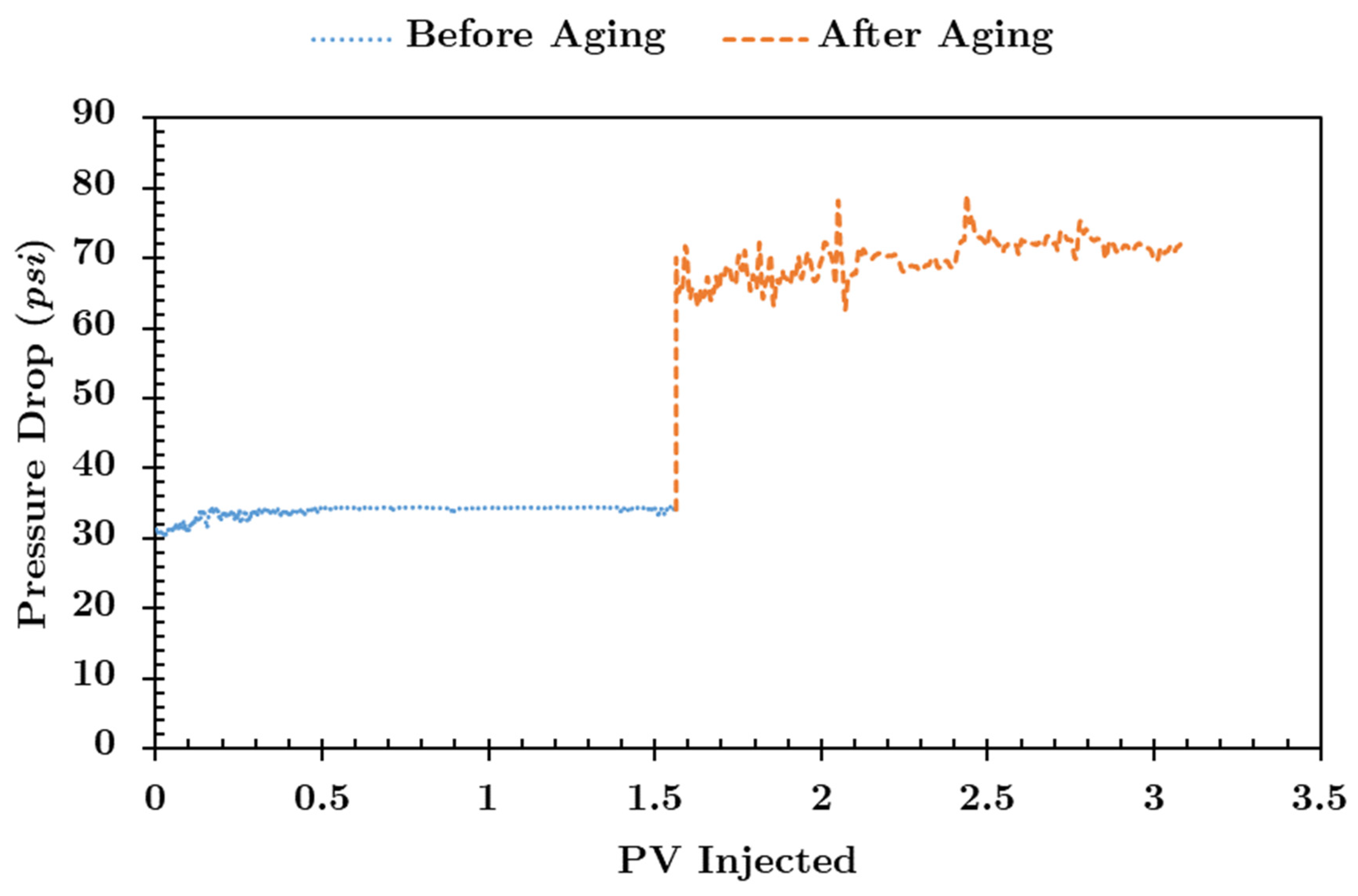
Since there was no water production during the crude oil injection after the aging period, the fluid saturations remained the same as before aging. Initial oil saturations shown in Table 5 indicate that the results are indeed comparable. The crude oil was injected at the same rate before and after aging, and the pressure drop turned out to be higher after aging. This leads to a lower kro according to Darcy’s law. If the rock underwent some wettability alteration away from water-wet and towards preferentially oil-wet, it would become harder for the oil to move inside the core because of its tendency to adhere to the pore walls. If the oil is encountering more resistance to being pushed out of the pores, there must be an increase in the measured pressure drop for the same flow rate. An example of this pressure change is shown in Figure 2 from Coreflood HC1. Similar pressure profiles were found for all cores presented here.

3. Results and Discussion

Table 5 shows a summary of the results of the experiments. Initial oil saturation (Soi) is reported, as well as waterflood residual oil saturation (Sorw), oil recovery (%ROIP), and LTG residual oil saturation (SorLTG).

3.1. Effect of Foam Quality in Oil-Wet Carbonates

Coreflood HC1. A waterflood was conducted at three increasing rates, 1, 3, and 10 ft/day, until residual oil saturation was reached. In this case, Sorw was 23%, as shown in Figure 3. Once there was zero oil cut in the effluent, the water injection rate was reduced back to 1 ft/day to obtain a baseline pressure drop measurement at Sorw. This will be later compared to the late-time drive-pressure drop at SorLTG. All hydrocarbon gas and nitrogen corefloods presented here follow this procedure.
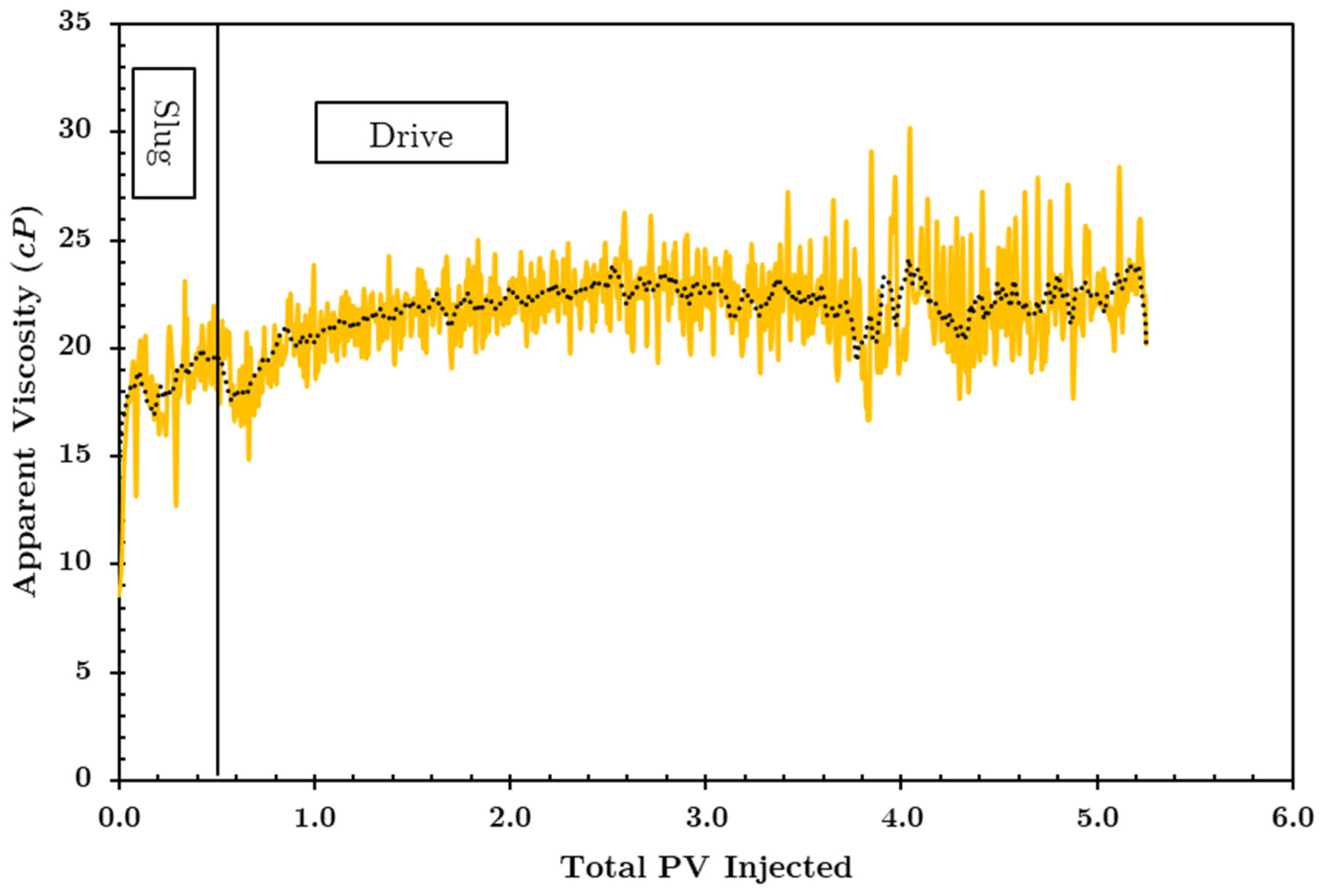
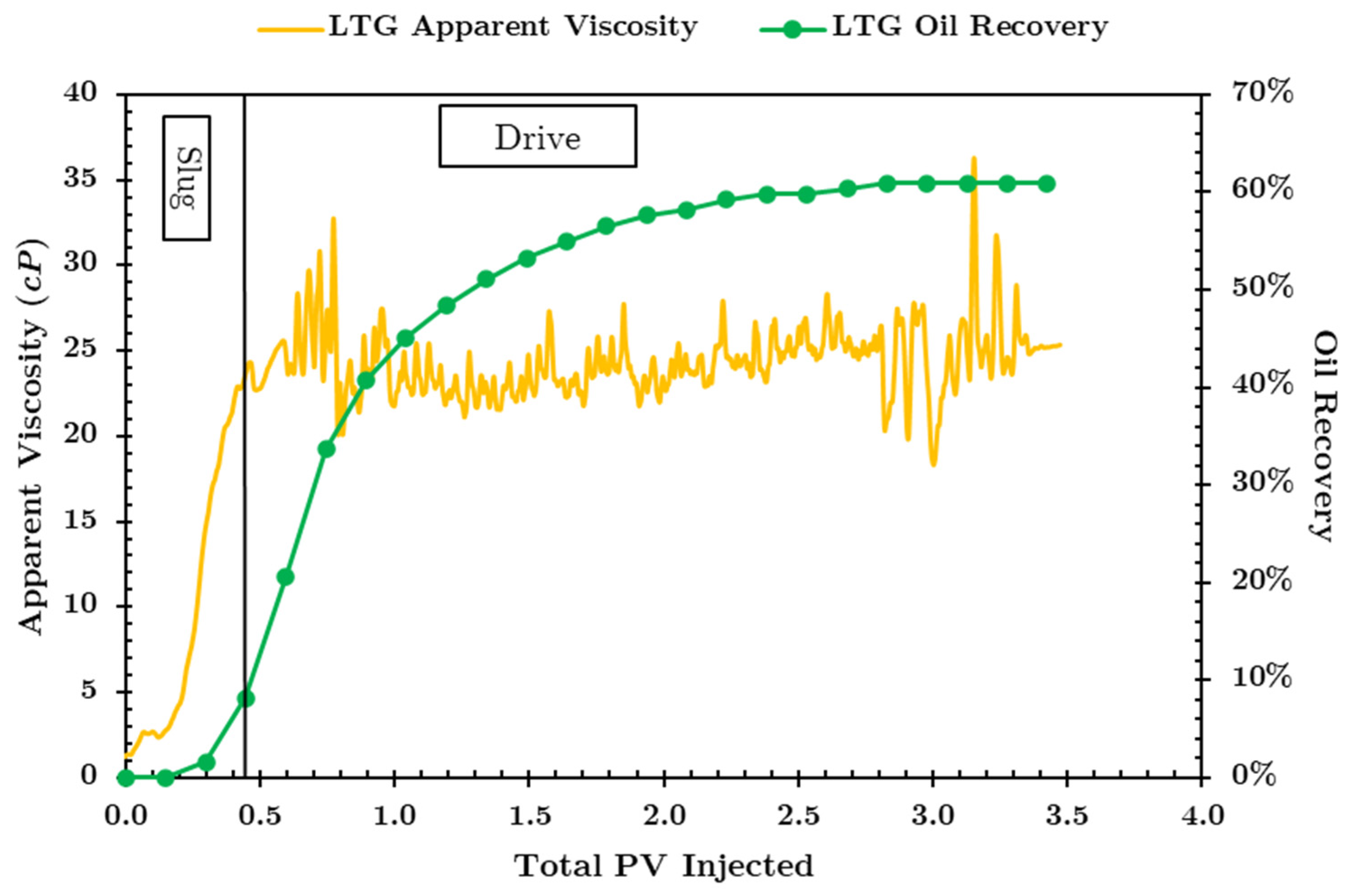
For this coreflood, the LTG injection scheme consisted of 40% foam quality for both the slug and the drive, with the slug being 0.3 liquid PV (LPV). The injection rate was 1 ft/day to simulate far-field conditions. The apparent viscosity for this coreflood is shown in Figure 4. For this and all subsequent figures, an average trendline is shown on top of the raw measured pressure data for easier reading.
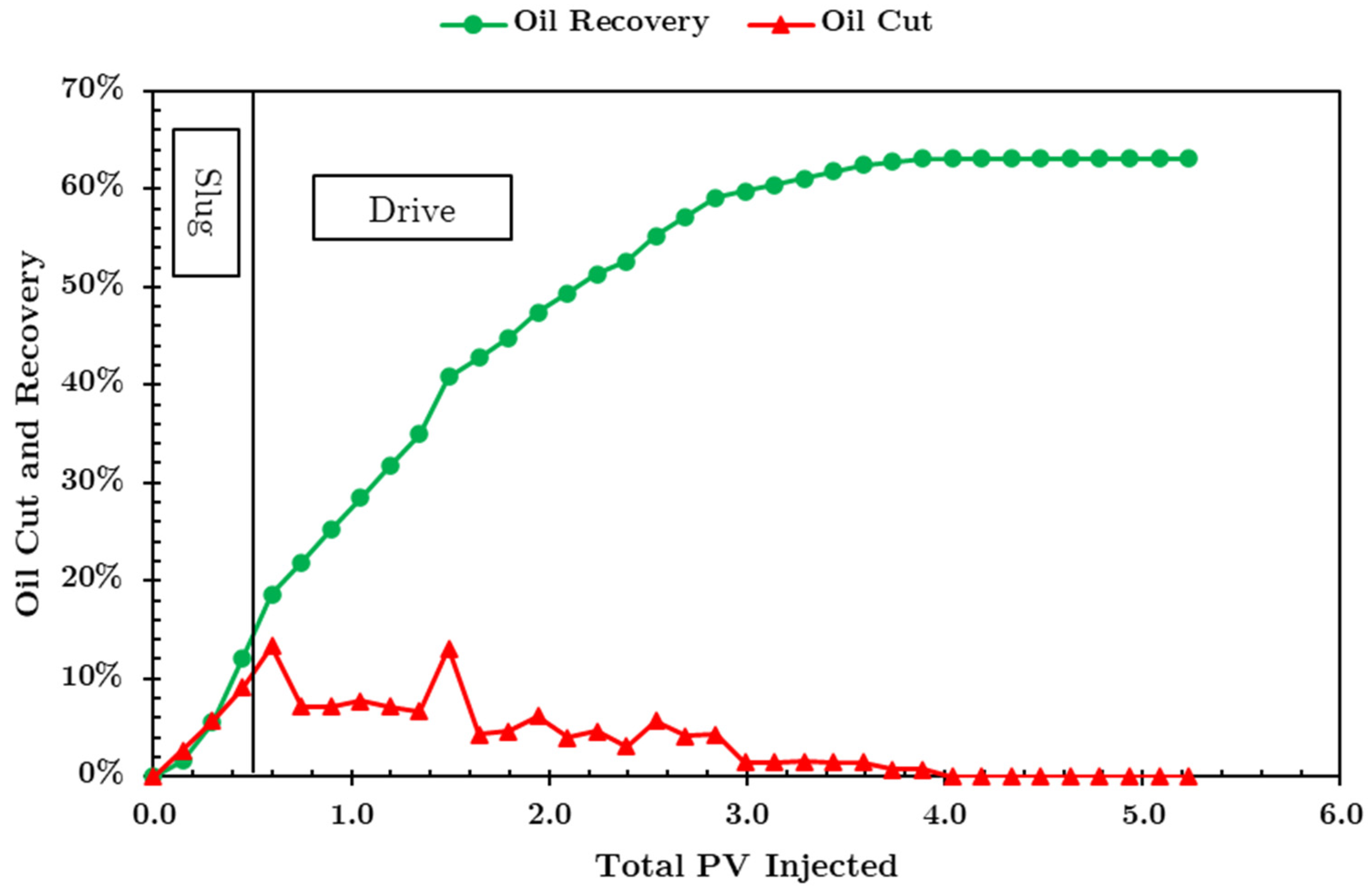
When the slug initially encounters the trapped oil, the reduced IFT and enhanced mobility control due to foam mobilizes the oil, which eventually forms an oil bank. This explains the initial increase in apparent viscosity seen during the slug injection. During the drive injection, the apparent viscosity is nearly constant at around 23 cP, and oil cut is also somewhat constant at approximately 5%, as seen in Figure 5. One would expect the viscosity to decrease as more oil is being produced. This is not observed here, and the steady-state apparent viscosity is significantly higher than that of the waterflood at the same rate. This can be attributed to two phenomena: the relative permeability effect of two-phase flow in low-permeability cores, and the generation of foam. The relative permeability of gas is greatly reduced due to gas trapping [26], and this trapped gas affects the mobility of the flowing aqueous phase by reducing its saturation [27]. This implies that for the same injection rate, a greater apparent viscosity is encountered. The apparent viscosity during the 10 ft/day waterflood stage reached a maximum value of 70 cP with no additional oil production, as seen in Figure 3. Therefore, any oil production during the LTG stage is not attributed to viscous forces. Hence, the reduction in IFT in the early time period leads to oil mobilization, and the reduced mobility of the displacing fluids in the late time period results in the additional recovery after the waterflood.
Looking at the oil recovery within 1 PV of total (liquid and gas) injection, 28% ROIP was achieved, and an ultimate recovery of 63% ROIP was achieved after 4 PV of total fluids was injected. The low yet steady oil cut from breakthrough until about 3 PV injected indicates that the mobilized oil fraction in the oil bank is low, which is not desirable. It would be more attractive to generate an oil bank with a higher oil cut faster to produce more oil within the first pore volume of total injection fluids. The following corefloods will focus on improving the oil recovery rate within 1 PV of total injection.
Coreflood HC2. The second coreflood using the hydrocarbon gas mixture was conducted using 60% foam quality during the LTG flood. As before, the LTG flood was preceded by a waterflood, which achieved an Sorw of about 20%. The same slug and drive compositions were injected at the same rate of 1 ft/day. The viscosity profile shown in Figure 6 resembles a more traditional one, where there exists an initial increase in apparent viscosity due to the mobilization of the oil bank and then a gradual decrease as the oil is being produced to reach a stead value at SorLTG.
The apparent viscosity maxed out at around 50 cP during the slug injection and reached a steady state value of 28 cP during the late time period of the drive. For this experiment, alcohol was injected after about 2.75 LPVs of drive. At that time, the apparent viscosity had been stable for more than 2 PVs and there was no more oil production. Single-phase injection of alcohol was observed to rapidly destabilize foam and decrease the apparent viscosity [11]. However, in this coreflood, the alcohol was co-injected with the hydrocarbon gas at the same gas quality as the drive, 60% in this case. The purpose behind this was to decouple the effect of foam and relative permeability reduction due to the two-phase flow in the low-permeability core. As mentioned [before, the presence of trapped gas saturation decreases the relative permeability of the injected fluids, resulting in a higher observed apparent viscosity. To eliminate the foam and maintain the two-phase flow effect, alcohol was injected at the same rate and gas quality. As can be seen in Figure 6, there is a very slow decreasing trend in the overall apparent viscosity across the core down to 25 cP, as opposed to a rapid reduction compared to single-phase alcohol injection [11]. The slight decrease in viscosity indicates that the foam, while present, is not very strong. It also implies that proper mobility control is still achievable in low-permeability oil-wet carbonates despite the lack of strong foam.
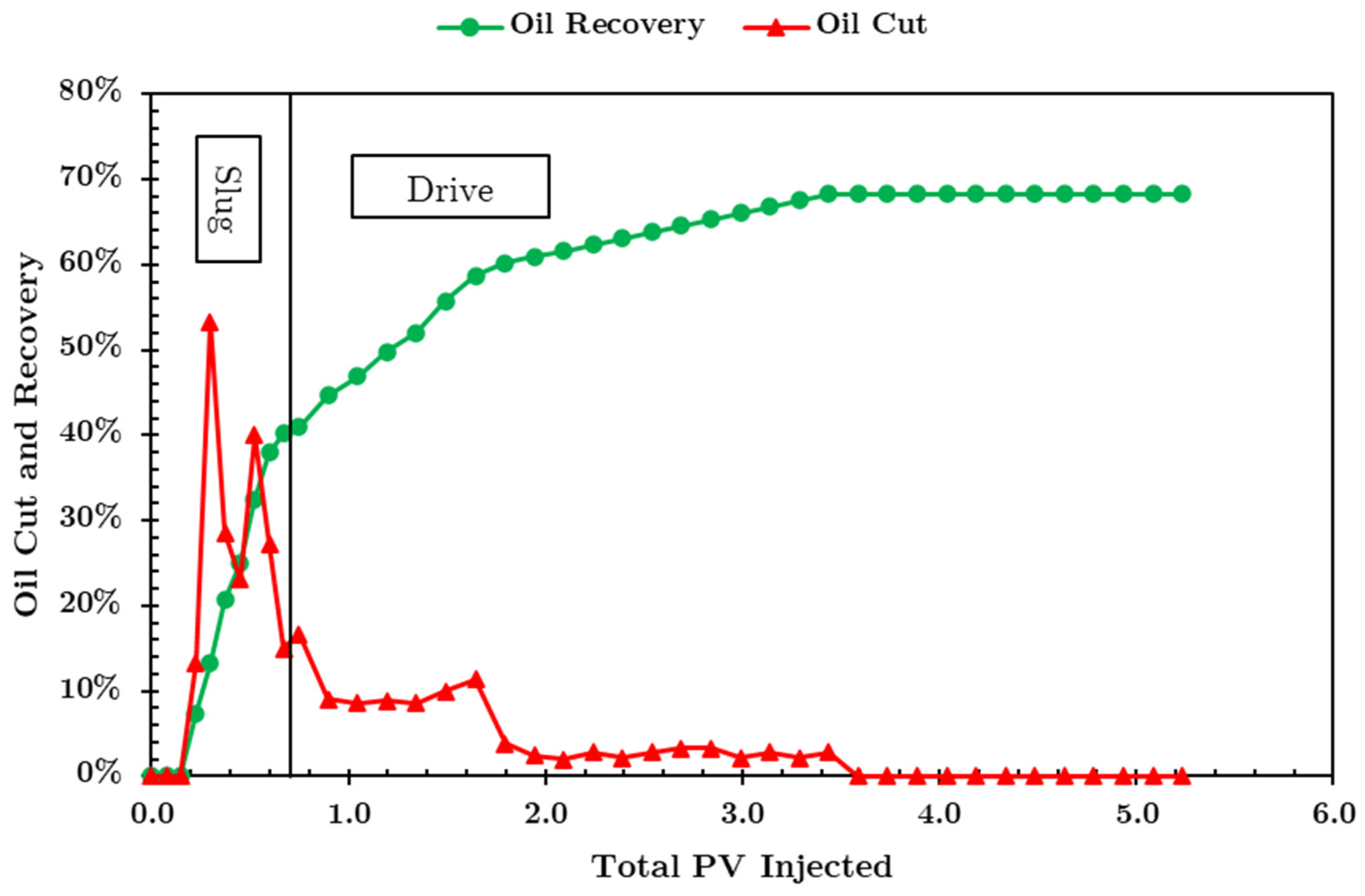
Looking at the ultimate oil recovery and recovery rate in Figure 7, it is clear that a much more substantial oil bank was formed as compared to Coreflood HC1 with 40% gas quality. About 50% ROIP was achieved within 1 PV of total injected fluids, and SorLTG is close to 70%. This coreflood shows much better mobility control, as evident by the large oil cut in the beginning, as well as sustained oil production until around 1.5 total PV injected. An added explanation is that the presence of more gas in the system in general is beneficial for the formation of Type III microemulsions in the core as it increases the solubilization of oil [24]. Phase behavior experiments showed that the optimal salinity for the live oil at 1000 psi is 179,000 ppm TDS. The dead crude oil was allowed to reach equilibrium with the hydrocarbon gas mixture at that elevated pressure in the microemulsion phase behavior experiments, whereas, in these coreflood experiments, the injected gas and slug solution come into contact with dead oil in the core. It follows then that the increased gas quality leads to more gas being absorbed into the dead oil, not only causing it to swell and reducing its viscosity (which also helps in improving recovery rate) but also allowing it to form Type III microemulsions more readily when compared to the 40% gas quality case. It must also be noted that the LTG flood in Coreflood HC2 started with 3% lower Sorw compared to Coreflood HC1 but showed a higher oil recovery, 68% compared to 63%, making the benefits of the 60% gas quality and microemulsion formation even more significant.
Coreflood HC3. This third experiment using the hydrocarbon gas mixture was performed at 80% gas quality. The waterflood preceding the LTG flood resulted in a Sorw of about 26%. The viscosity profile of this coreflood, as shown in Figure 8, does not show the initial increase during the slug as seen in the previous two experiments. This may be attributed to the higher Sorw as compared to the previous two experiments. To better understand this observation, further analysis needs to be performed on the oil recovery data.
Looking at Figure 9, it is apparent that the recovery rate is poor. There was barely any oil production within 1 PV, and the ultimate recovery only reached 51% ROIP. At around 1.2 PVs in total injected, the oil cut increases significantly and is sustained for around 2 PVs. Converting total PVs injected into liquid PVs injected with 80% gas quality gives about 0.25 PVs of liquid injected, which is only slightly smaller than the designed slug size. This is important because it means that the total amount of desired surfactant (0.3 LPV) will take longer to be fully injected. Therefore, at the same given moment, there is less volume of surfactant in the core to form Type III microemulsions and reduce IFT as compared to the previous corefloods. Looking just at the total PVs injected will give an overly pessimistic interpretation because there is so much gas being injected at 80% gas quality that it takes 1.5 PVs of total injection just to inject the entire 0.3 LPV slug. However, this does have a positive side effect: the presence of more gas in the core at the higher gas quality means there is more gas available for the oil to absorb, swell, and become less viscous and more mobile. This is evident by a large oil cut at breakthrough. It can be said that the oil recovery of this experiment is comparable to that of Coreflood HC2 but delayed due the increased amount of gas being co-injected. Unfortunately, this is still undesirable economically, making the produced oil bank too late to matter in any field application.
An additional coreflood was performed with the intent to determine the effect of the injection rate on the steady-state apparent foam viscosity as well as oil recovery in low-permeability oil-wet carbonates. For this purpose, a core with similar properties was used, with all other injection parameters being the same as the previous corefloods expect the injection flow rate and foam quality. The rate was doubled to 2 ft/day and the foam quality was further reduced to 30%. This means that the 0.3 LPV slug would be delivered faster. The apparent viscosity and oil recovery results are shown in Figure 10.
The apparent viscosity initially increased then stabilized at around 23 cP, comparable to the corefloods conducted at the lower rate. Looking at the oil recovery, ROIP reached around 40% within the first PV of total injected fluids, similar to Coreflood HC2, and the total oil recovery reached above 60% ROIP after about 3 PV of total injected fluids, slightly less than Coreflood HC2. The increase in injection rate and decrease in injection foam quality did not significantly affect oil production or mobility control. This coreflood shows that it is possible to reduce the injection rate by half (from 2 ft/day to 1 ft/day) and still maintain both proper mobility control and economically attractive oil recovery rates within 1 PV of total injection, as seen in Corefloods HC1-HC3.
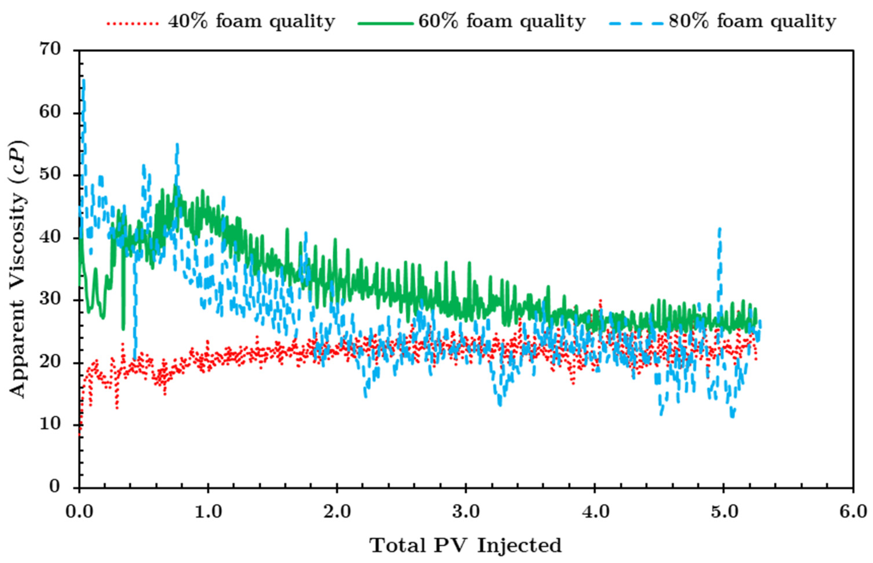
Figure 11 shows the viscosity profile of the three hydrocarbon corefloods. Looking at the early time period, Coreflood HC1 at 40% foam quality had a long and thin oil bank, as seen from the oil cut in Figure 5, which would explain the lack of a typically observed increase then decrease in apparent viscosity indicative of the mobilization of a significant oil bank. Increasing the foam quality to 60% in Coreflood HC2 resulted in a thicker oil bank, which explains the initial increase in viscosity. Once the oil broke through and oil saturation decreased significantly, the viscosity also started to decrease. Coreflood HC3 at 80% foam quality started at a higher viscosity than Coreflood HC1 or Coreflood HC2. This can be attributed to the fact that the initial oil saturation for LTG (Sorw) is higher for Coreflood HC3 (26%) than for Coreflood HC1 (23%) or Coreflood HC2 (20%). This means that the injected fluids are encountering a larger volume of immobile oil after the waterflood. Another explanation is that the in situ gas saturation at 80% foam quality is higher than that for the two other cases (35% as opposed to 25%), which causes a greater reduction in the total mobility of the injected fluids [21], thus increasing the measured apparent viscosity.
Looking at the late-time apparent viscosities, the three tested foam qualities (40–60–80%) show the same average value. This shows that there is no significant change in foam behavior in low-permeability oil-wet carbonates under these conditions. Early work has shown that surfactant adsorption in oil-wet cores can be significant and leads to weaker foam generation [28]. For all experiments, the apparent viscosity during the late-time drive was significantly higher than during the waterflood at Sorw. Oil is produced during the slug propagation through the core, so the residual oil at the late time period of the drive is lower than that of the late-time waterflood. Based on this, a lower apparent viscosity is expected across the core provided the same injection conditions are maintained. However, in all of the HC experiments, there is a significantly higher apparent viscosity even at the lower oil saturations. This can be attributed to two factors: relative permeability effects due to two-phase gas–water flow that leads to a decrease in fluid mobility, and generation of foam during the drive injection, which increases the trapped gas saturation and increases the effective gas phase viscosity [29]. Alcohol and gas co-injection, which destabilized foam, showed only a small decrease in the apparent viscosity after the drive, leading to the conclusion that proper mobility control can still be achieved in low-permeability oil-wet carbonates during two-phase flow even in the absence of strong foam.
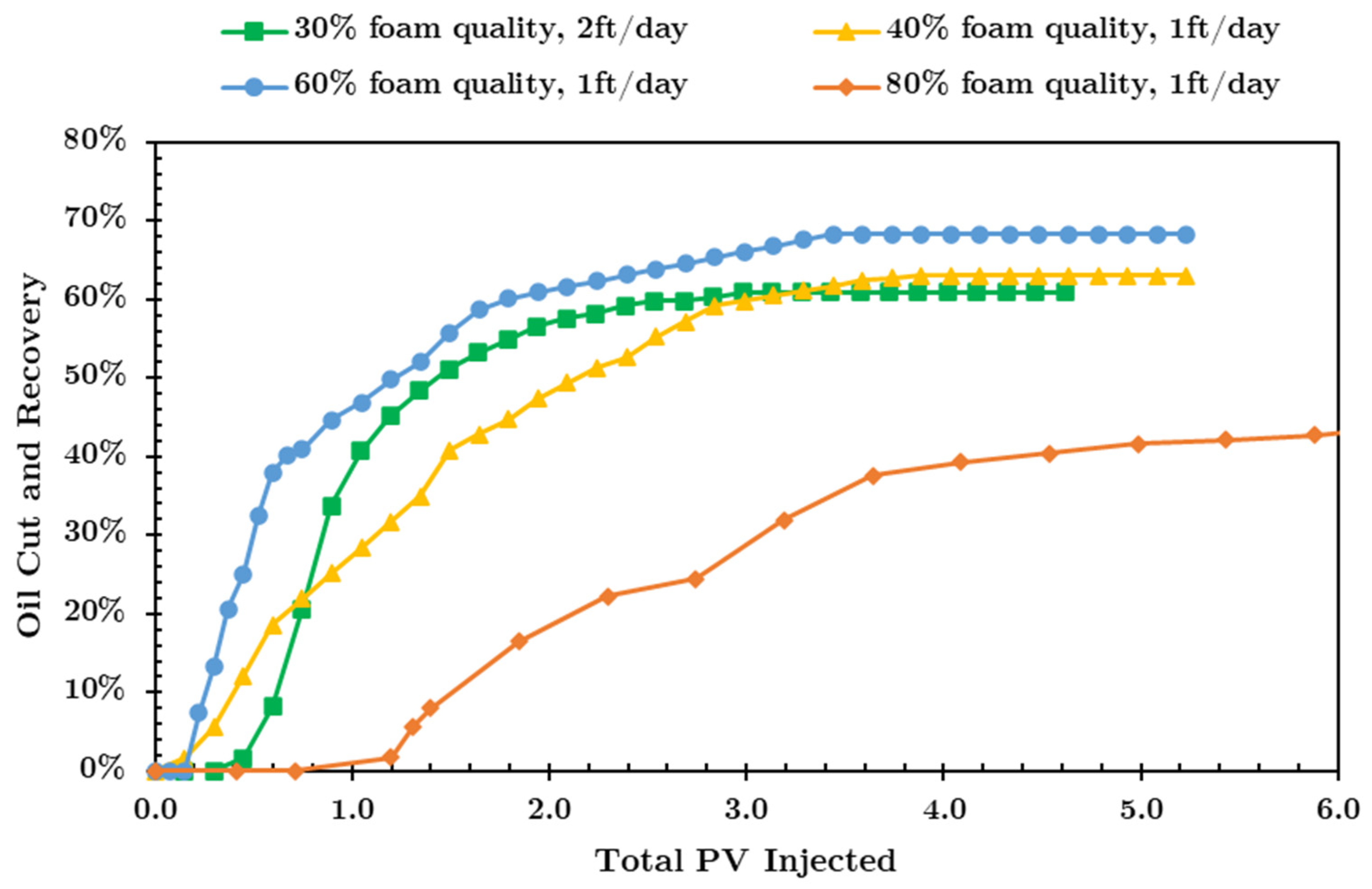
Looking at the oil recoveries in Figure 12, it is clear that the 80% case is the worst while the 60% case is the best, even when compared to the 30% case at 2 ft/day. This is from the perspective of the oil recovery at 1 PV of total injection, but it is also true for the ultimate recovery. Given that the injection gas was 85–15% methane–ethane, there will be some level of interaction between the gas and the dead oil in the core. When hydrocarbon gas comes into contact with the oil, some of it dissolves in the oil, causing it to swell. This will decrease the viscosity of the oil, allowing it to flow more easily. Additionally, the hydrocarbon gas will increase the solubilization ratio in the presence of the slug surfactant [24]. All of these factors lead to an increase in oil production.
For the case of 80% foam quality, we expect the large amount of gas present to cause a significant amount of interaction with the oil, leading to a higher recovery rate. This was not the case, however. Despite the relatively large oil bank seen in the oil cut in Figure 9, which indicates a significant amount of oil swelling, reduced oil viscosity and oil mobilization, the oil breakthrough was much later compared to Coreflood HC1 and Coreflood HC2. It is important to note that at 80% injection foam quality, only 20% of the first PV injected is liquid surfactant. The entire slug is 0.3 LPV, meaning that by the time 1 PV of total injection was reached, only 67% of the slug had been injected. This would also contribute to the poor oil recovery at 1 PV of total injected fluid, since not all the desired amount of surfactant in the slug was injected [30].
For the case of 60% foam, around 50% oil recovery was achieved within 1 PV of total injected fluid. It also achieved the highest ultimate recovery, around 68% ROIP. It is hypothesized that this foam quality led to favorable interaction between the oil and the gas, including oil swelling, viscosity reduction, and an increased solubilization ratio, all of which contribute to the good oil recovery. This can also be seen from the viscosity profile: there seems to be a relatively substantial mobile oil bank as compared to the 40% case.
Comparing the lower injection rate experiments Coreflood HC1, HC2 and HC3 to the reference coreflood in Figure 12 shows that reducing the rate does not negatively impact mobility control, as seen by the comparable apparent viscosities. Also, Coreflood HC2 at 60% foam quality was able to achieve a better oil recovery rate: 50% ROIP vs. 40% ROIP at 1 PV of total injection. Thus, the lower rate coreflood was successful in the following aspects: (i) mobility control was still maintained and (ii) oil recovery within 1 PV was acceptable.
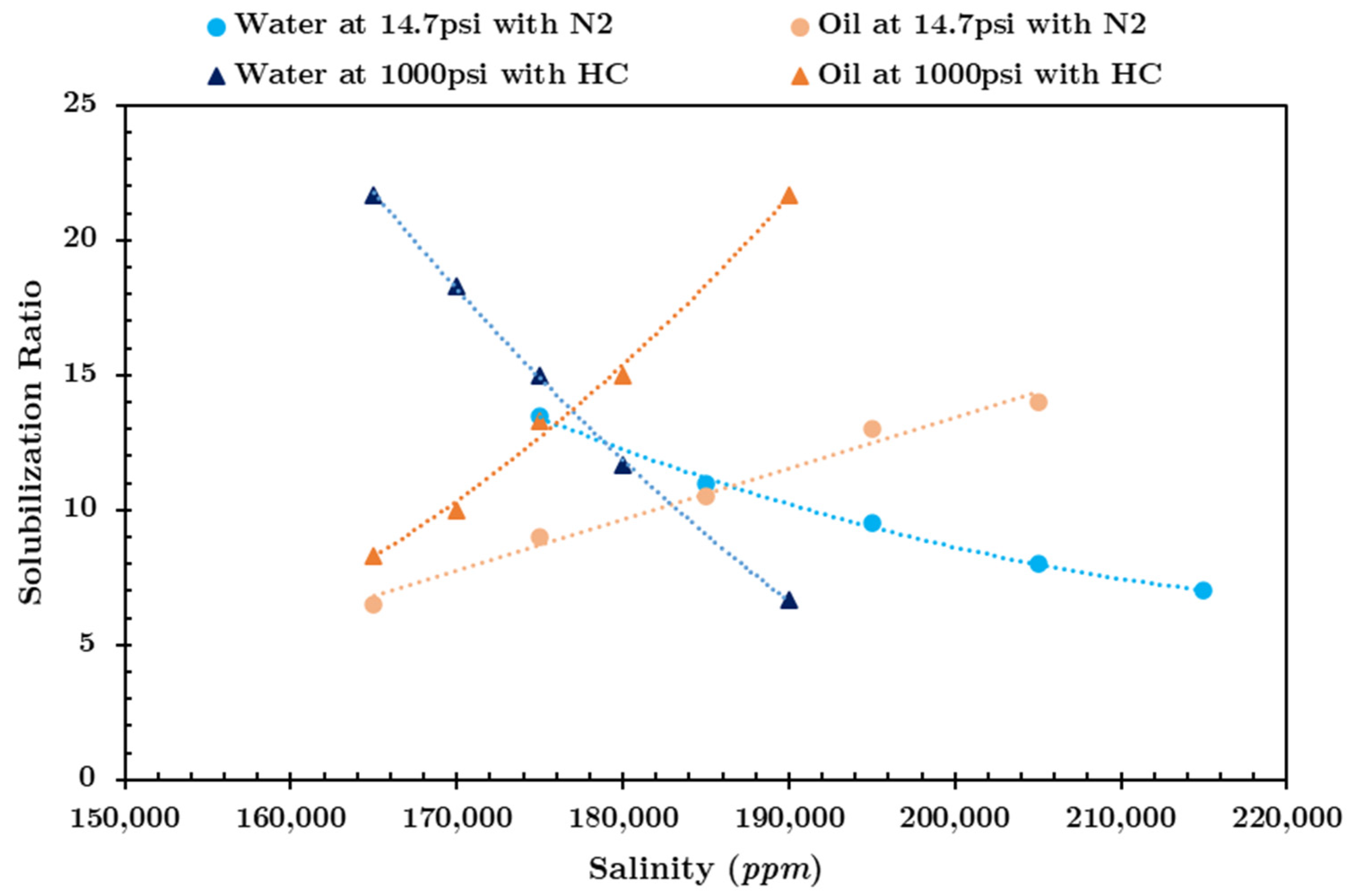
A major component in LTG floods is IFT reduction. This is achieved by creating a Type III microemulsion environment in the core at optimum salinity in the presence of oil, water, gas, and surfactant. This optimum salinity is affected by the oil composition, which would be different based on the type of gas used. Work carried out early on showed that adding methane to dead crude oil decreases the optimum salinity and increases the solubilization ratio [31]. Similar studies show that ethane also has the effect of reducing the optimum salinity [24,32]. It is also noted that the type of gas influences the achieved foam strength at different foam qualities [33]. Although it is more convenient to use available on-site produced hydrocarbon gas for LTG injection, it is still important to evaluate the effect of dissolved hydrocarbon gas on microemulsion formation in low-permeability oil-wet carbonate cores. It has been observed that there is no significant difference in steady-state foam strength between methane and nitrogen [34]. To that effect, the hydrocarbon gas mixture was replaced with nitrogen, which is not oil soluble. This will eliminate any of the positive interactions that the hydrocarbon gas has with the oil in terms of oil swelling and viscosity reduction, and most importantly, microemulsion behavior. As can be seen in Figure 13, the optimum salinity using nitrogen with the surfactant slug is around 186,000 ppm at atmospheric pressure and 69 °C. Increasing the pressure to 1000 psi has no effect on optimum salinity. The optimum salinity for the methane–ethane mixture is slightly lower at 179,000 ppm at the elevated pressure. The solubilization ratio using nitrogen was around 11 and does not change with higher pressure, while that of the HC mixture was higher at 14. This agrees with previous work showing that using hydrocarbon gas instead of nitrogen lowers the optimum salinity and increases the solubilization ratio [24]. An increase in the solubilization ratio results in further IFT reduction and, thus, oil recovery improvement.

3.2. Effect of Gas Type and Salinity Shift on LTG Performance

Based on the observation that 60% foam quality was the best in oil-wet carbonates with low permeability in terms of the oil recovery rate and ultimate recovery, the next two experiments focused on the importance of the type of gas injected on oil recovery during LTG in terms of solubility and Type III salinity shift.
Coreflood N1. This first experiment was conducted at 179,000 ppm with nitrogen. This effectively eliminates the HC gas-oil interactions given the drastically reduced solubility of nitrogen in the dead crude oil. This means that any production that occurs can mainly be attributed to a reduction in IFT through the formation of Type III microemulsions. Figure 13 suggests that injecting nitrogen at 179,000 ppm is right at the border of Type I and Type III microemulsion formation.
The viscosity profile in Figure 14 shows the same trend of an initial increase then gradual decrease as oil is being produced during the slug to reach steady state at the late-time drive. The average apparent viscosity during the late-time drive was about 9 cP. This is lower than the three HC gas experiments where the apparent viscosity was around 25 cP, but it is still higher than the waterflood at the same injection rate. Again, at lower oil saturation (Sorw = 21% vs. SorLTG = 14%), one would expect a lower apparent viscosity. This was not the case, however, due to the reduction in the mobility of the injected fluids and the generation of foam.
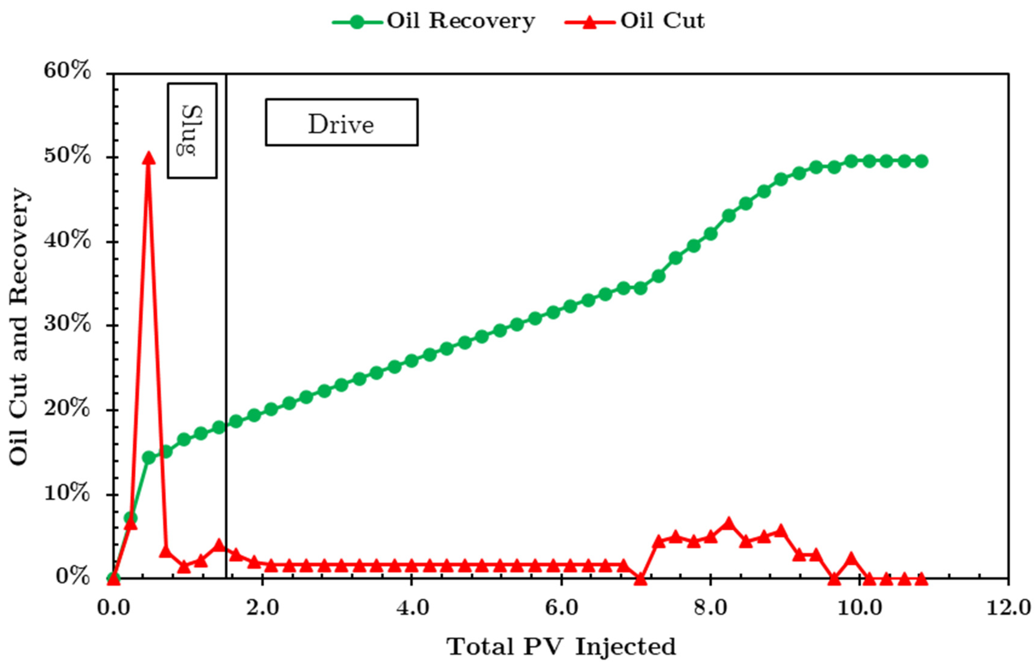
Figure 15 shows that there is no substantial oil production before 7 PV injected. This means that the remaining oil saturation in the core is higher during the late-time drive injection (SorLTG = 35%).
Several studies have shown that there is a detrimental effect on foam performance with increasing oil saturation, with various theories on the mechanisms behind it [35]. As a specific example, one study in aged cores showed that for field gas, methane, and nitrogen, foam strength decreased from around 1000 cP to only 200 cP as oil saturation increased from 13% to 19% [36]. Unstable foam would lead to comparatively lower apparent viscosities [37,38]. Additionally, the in situ gas saturation during the coreflood was measured to be only 13%, compared to the HC corefloods where the gas saturation was around 25–35%. This reduced gas saturation leads to a smaller reduction in fluid mobilities, which explains the lower apparent viscosities measured in this coreflood. Therefore, the slow recovery and low oil cut shown within the first 7 PVs can be attributed to poor mobility control due to the presence of higher oil saturation and lower gas saturation, which resulted in lower apparent viscosities during the drive injection.
Injection of alcohol after the APG drive at the same gas quality showed the effluent with very clear Type I microemulsion being produced. The alcohol mobilized the microemulsions that were not produced while the APG was being injected, which led the oil recovery to increase substantially from 35% ROIP to the drive injection up to 50% ROIP. The alcohol injection salinity was much lower than the lower salinity limit of Type III microemulsion formation, so the in situ salinity of 179,000 ppm became diluted. At this reduced salinity, Type III microemulsions turn into Type I microemulsion, where there is oil in the aqueous phase with an excess oil phase [39,40]. The reason we observe the production of this microemulsion is due to the relatively high oil saturation remaining inside the core after about 7 PVs of injection. There is more oil available to be mobilized in Coreflood N1 (SorLTG = 14%) as opposed to Coreflood HC2 where alcohol injection was also performed (SorLTG = 7%), which explains why there was oil production in the former but not in the latter. The viscosity profile during alcohol injection is representative of a secondary oil bank being mobilized through the core.
This shows that replacing the HC gas mixture with nitrogen has a negative effect on both the oil production rate and ultimate oil recovery, the reason being that the nitrogen gas does not significantly absorb into the oil, thus having no effect on the oil volume (swelling) or its viscosity. An added factor is the fact that the surfactant injection salinity was at 179,000 ppm instead of the optimum salinity of nitrogen at those conditions of 186,000 ppm. This highlights the importance of having optimum Type III microemulsion conditions to reduce IFT to ultra-low values in LTG floods, which is further investigated in the next coreflood.
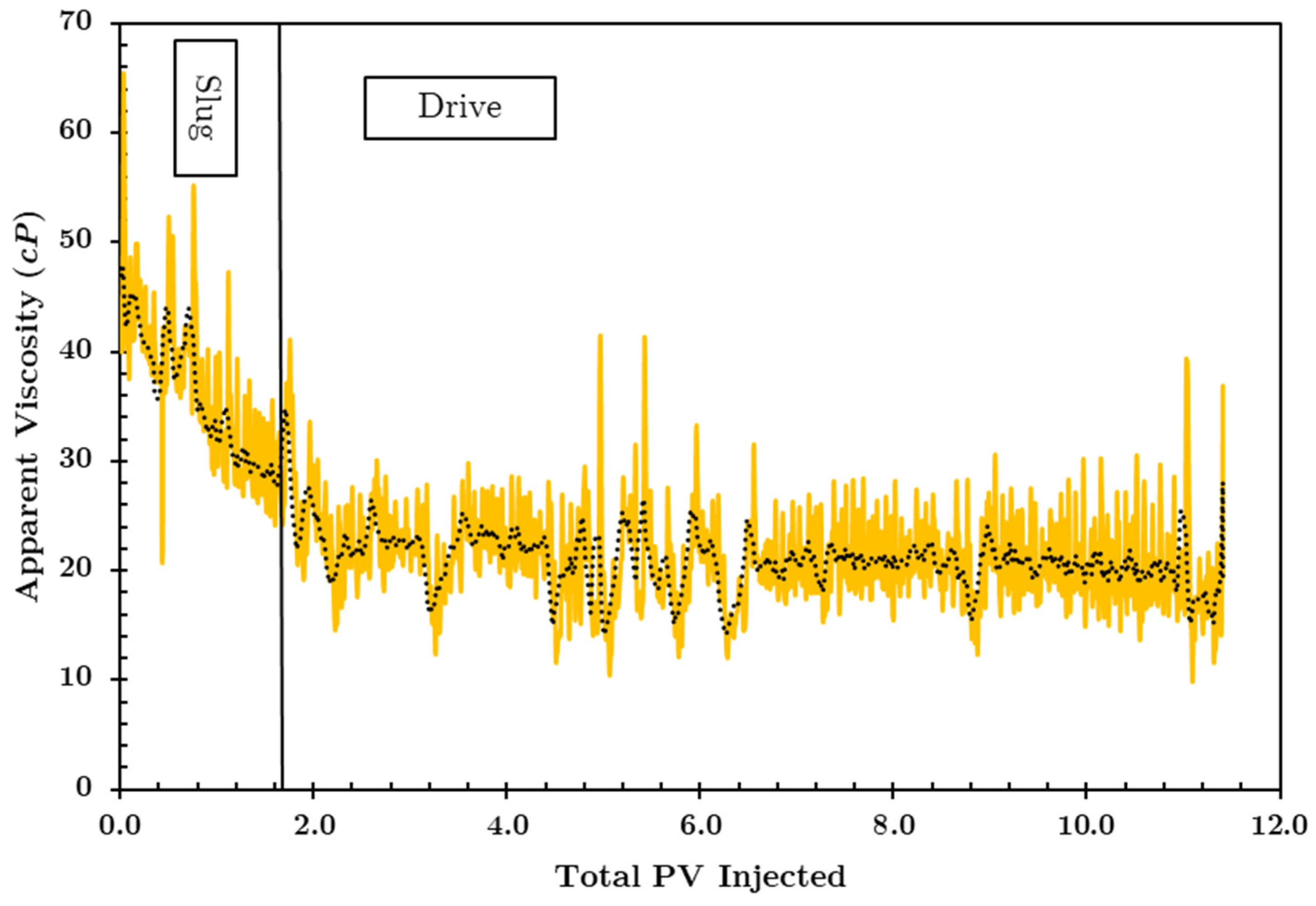
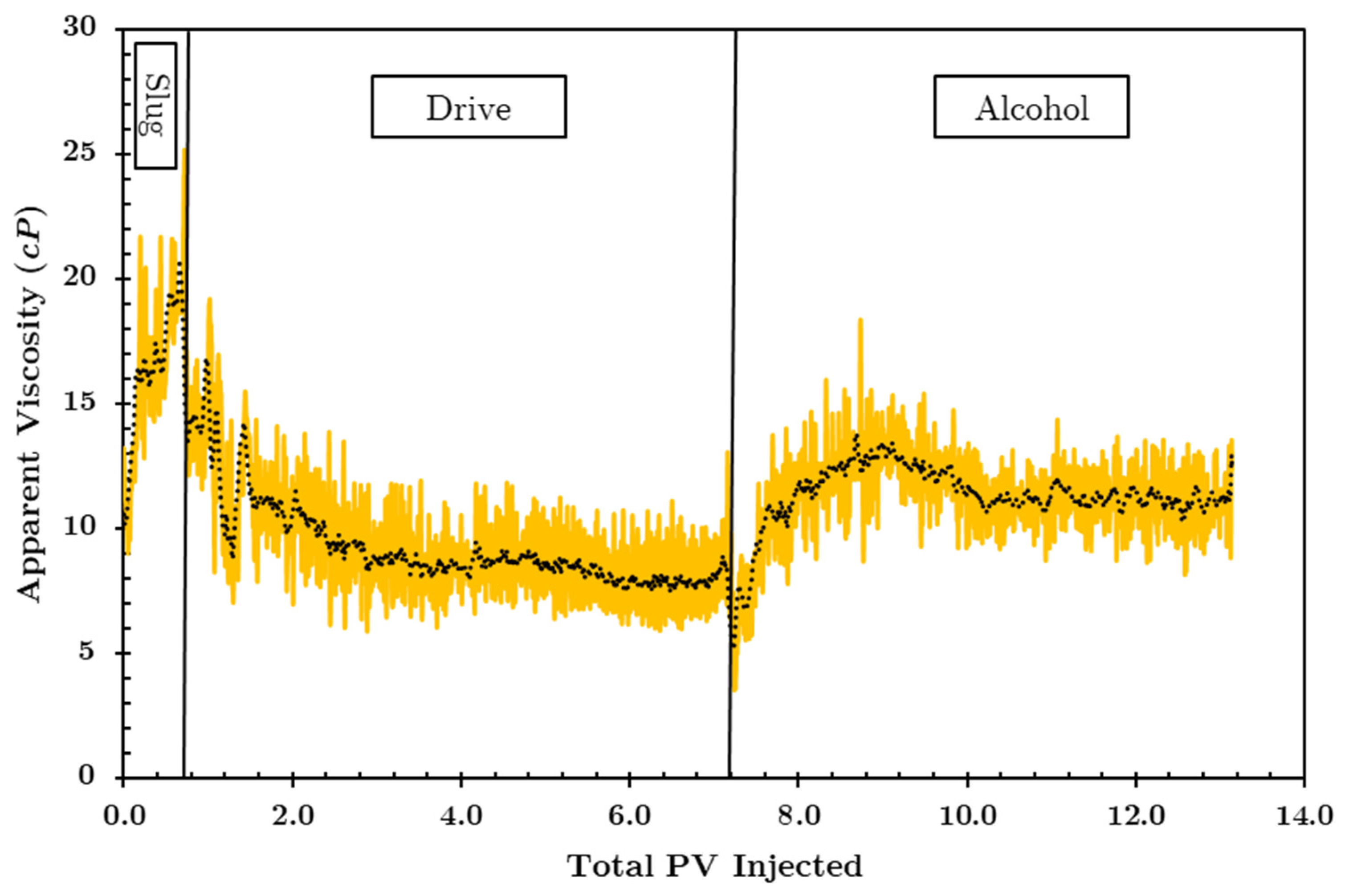
Coreflood N2. This experiment serves to show the importance of accounting for the shift in optimum salinity based on the gas type on the oil recovery and recovery rate. It maintained the same conditions as Coreflood N1 except that the LTG flood was conducted at the optimum salinity of nitrogen, which is 186,000 ppm using this surfactant formulation, re-introducing ultra-low IFT conditions in the core, while still eliminating the effect of the HC gas mixture on the oil. Figure 16 shows an initial increase in apparent viscosity during the slug injection, indicating the mobilization of a large oil bank. As that oil is being produced, the viscosity decreases until it reaches a steady state at around 8 cP. This is the lowest late-time drive injection apparent viscosity seen in these experiments. This can be attributed to the lowest remaining oil saturation during that injection step: 5%. Alcohol was co-injected at 60% gas quality after about 3.5 LPV injection (8.8 total PV). As can be seen from Figure 16, the apparent viscosity decreased from 8 cP to about 5 cP, indicating that foam was present and is being destabilized by the alcohol. The stabilization of the pressure drop after this decrease is an indication of the relative permeability effect. The remaining gas saturation in the core reduces the mobility of the injected fluids, resulting in an apparent viscosity greater than that of the waterflood at the same injection rate, despite the significantly lower oil saturation.
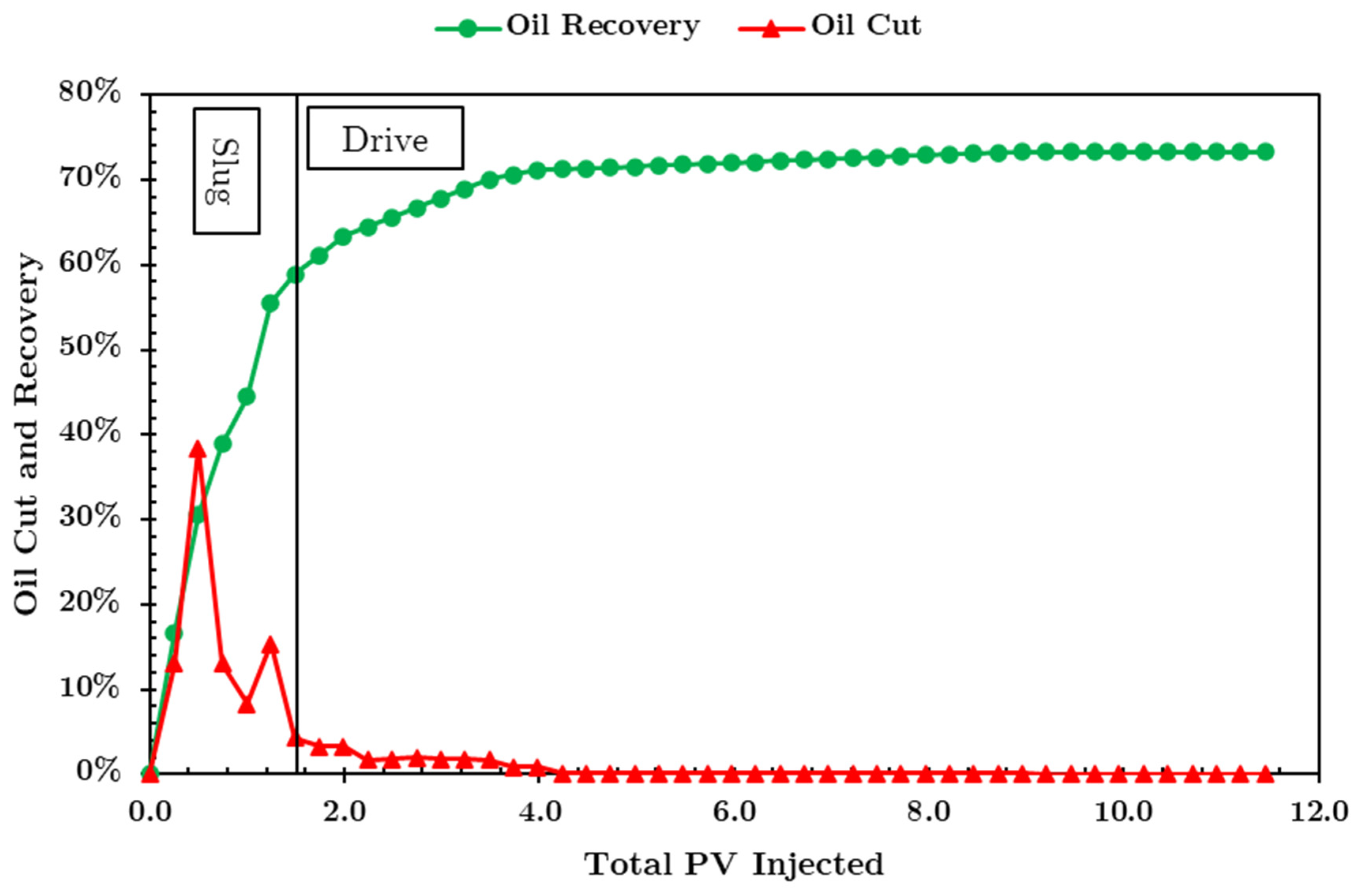
The oil recovery data are shown in Figure 17. Within 1 PV of total injection fluids, ROIP reached 50%, with relatively high oil cut. This elevated recovery rate as compared to Coreflood N1 correlates with the nitrogen optimum salinity, leading to better Type III microemulsion formation. Although the oil cut was extremely low after about 2 PV injected, the ultimate oil recovery reached 72%. This indicates that most of the oil is mobilized during the slug injection because of the reduced IFT, and in the early drive injection time as the foam provides good mobility control for that mobilized oil. This is the most desirable result as most of the oil is produced within 1 PV of total injection.
Figure 18 shows the oil recoveries of the best HC experiment, Coreflood HC2, compared against the two nitrogen experiments, Coreflood N1 and Coreflood N2. The dominant effect of IFT reduction is apparent. In Coreflood N1, the LTG flood was conducted at 179,000 ppm, which is not the optimum salinity of nitrogen where oil and water solubilize equally in the Type III microemulsion phase. This led to a poor recovery rate as well as poor ultimate recovery when compared to the two other experiments. Coreflood HC2 and Coreflood N2 were conducted at the respective optimum salinity of the methane–ethane mixture and nitrogen. Both resulted in around 50% ROIP within 1 PV injected, with Coreflood N2 having a slightly higher ultimate oil recovery after about 4 PV injected. These results show that it is possible to apply LTG as a tertiary recovery technique in low-permeability oil-wet carbonates and be economically attractive in terms of the oil recovery rate as well as ultimate oil recovery. Also, the results indicate that under the conditions present here, changing gas type from a HC gas mixture to nitrogen does not negatively affect the performance provided the gas is injected at its optimum salinity.

4. Conclusions

The performance of LTG in low-permeability oil-wet carbonates was investigated by looking at the impact of gas quality and gas type on the oil recovery rate within the first PV of injection. The following conclusions have been determined:
  • For low-permeability oil-wet carbonates, 60% injection gas fraction is optimal in terms of oil recovery compared to 40% or 80%, as it provides a balance between proper Type III microemulsion formation and good mobility control.
  • Proper mobility control was achieved in low-permeability oil-wet carbonates despite the lack of strong foam.
  • It was shown that gas type has an effect on microemulsion phase behavior during corefloods. The 85–15% methane-ethane hydrocarbon gas mixture had a lower optimum salinity and higher solubilization ratio as compared to nitrogen at 1000 psi. Accounting for this shift in salinity during coreflood injection led to a 50% ROIP recovery within 1 PV of total injected fluids.
  • Regardless of the gas type, it is necessary to inject at the optimum salinity of that gas at the respective pressure to achieve higher oil recovery rates.
  • Injecting at a lower rate (1 ft/day vs. 2 ft/day) proved to be viable as the oil recovery rate was the same and the foam strength was comparable. This shows that laboratory corefloods can be expedited by conducting them at higher rates without compromising the results.

Author Contributions

Conceptualization, D.H. and Q.P.N.; methodology, D.H. and Q.P.N.; data curation, D.H.; writing—original draft preparation, D.H.; writing—review and editing, Q.P.N.; supervision, Q.P.N.; funding acquisition, Q.P.N. All authors have read and agreed to the published version of the manuscript.

Funding

This research was funded by the Chemical EOR Consortium (grant number UTA 200502565) and Shell (grant number UTA13-000410). The funder was not involved in the study design, collection, analysis, interpretation of data, the writing of this article or the decision to submit it for publication.

Data Availability Statement

Data are contained within the article.

Acknowledgments

We thank Rouhi Farajzadeh, Ramez Nasralla, and Siavash Kahrobaei at Shell for their valuable comments and technical discussions throughout all aspects of our study.

Conflicts of Interest

The authors declare no conflict of interest.

References

  1. Vishnyakov, V.; Sileimanov, B.; Salmanov, A.; Zenalov, E. Primer on Enhanced Oil Recovery, 1st ed.; Gulf Professional Publishing: Oxford, UK, 2019. [Google Scholar]
  2. Sheng, J.J. Modern Chemical Enhanced Oil Recovery: Theory and Practice; Gulf Professional Publishing: Oxford, UK, 2011. [Google Scholar]
  3. Gbadamosi, A.O.; Junin, R.; Manan, M.A.; Agi, A.; Yusuff, A.S. An overview of chemical enhanced oil recovery: Recent advances and prospects. Int. Nano Lett. 2019, 9, 171–202. [Google Scholar] [CrossRef]
  4. Ahmed, T.; Meehan, D.N. Advanced Reservoir Management and Engineering; Gulf Professional Publishing: Oxford, UK, 2011. [Google Scholar]
  5. Fink, J. Petroleum Engineer’s Guide to Oil Field Chemicals and Fluids, 2nd ed.; Gulf Professional Publishing: Oxford, UK, 2012. [Google Scholar]
  6. Manrique, E.J.; Muci, V.E.; Gurfinkel, M.E. EOR field experiences in carbonate reservoirs in the United States. SPE Reserv. Eval. Eng. 2007, 10, 667–686. [Google Scholar] [CrossRef]
  7. Christensen, J.R.; Stenby, E.H.; Skauge, A. Review of WAG field experience. SPE Reserv. Eval. Eng. 2001, 4, 97–106. [Google Scholar] [CrossRef]
  8. Wang, Z.H.; Sun, B.-W.; Guo, P.; Wang, S.-S.; Liu, H.; Liu, Y.; Zhou, D.-Y.; Zhou, B. Investigation of flue gas water-alternating gas (flue gas–WAG) injection for enhanced oil recovery and multicomponent flue gas storage in the post-waterflooding reservoir. Pet. Sci. 2021, 18, 870–882. [Google Scholar] [CrossRef]
  9. Xue, W.; Wang, Y.; Chen, Z.; Liu, H. An integrated model with stable numerical methods for fractured underground gas storage. J. Clean. Prod. 2023, 393, 136268. [Google Scholar] [CrossRef]
  10. Johns, R.T.; Dindoruk, B. Enhanced Oil Recovery Field Case Studies, 1st ed.; Gulf Professional Publishing: Oxford, UK, 2013. [Google Scholar]
  11. Das, A. Enhanced Oil Recovery Using Low Tension Gas Flooding in High Salnity, Low Permeability Carbonate Reservoirs. Ph.D. Thesis, Univeristy of Texas at Austin, Austin, TX, USA, 2018. [Google Scholar]
  12. Kamal, M.; Marsden, S.S. Displacement of a micellar slug foam in unconsolidated porous media. In Proceedings of the SPE Annual Technical Conference and Exhibition? Las Vegas, NV, USA, 30 September–3 October 1973. [Google Scholar] [CrossRef]
  13. Lawson, J.B.; Reisberg, J. Alternate Slugs of Gas and Dilute Surfactant for Mobility Control During Chemical Flooding. In Proceedings of the Fall Meeting of the Society of Petroleum Engineers of AIME, Las Vegas, NV, USA, 30 September–3 October 1980. [Google Scholar] [CrossRef]
  14. Srivastava, M.; Zhang, J.; Nguyen, Q.P.; Pope, G.A. A systematic study of Alkaline-Surfactant-Gas injection as an EOR technique. In Proceedings of the SPE/DOE Enhanced Oil Recovery Symposium, Tulsa, Oklahoma, 20–23 April 2009. [Google Scholar]
  15. Srivastava, M.; Nguyen, Q.P. Application of gas for mobility control in chemical EOR in problematic carbonate reservoirs. SPE—DOE Improv. Oil Recover. Symp. Proc. 2010, 2, 794–809. [Google Scholar] [CrossRef]
  16. Cottin, C.; Morel, D.; Levitt, D.; Cordelier, P.; Pope, G. Alkali Surfactant Gas Injection—Attractive Laboratory Results in Carbonates under Harsh Salinity and High Temperature; European Association of Geoscientists & Engineers: Utrecht, The Netherlands, 2012. [Google Scholar] [CrossRef]
  17. Speight, J. Heavy Oil Recovery and Upgrading; Gulf Professional Publishing: Oxford, UK, 2019. [Google Scholar]
  18. Shi, J.-X.; Rossen, W.R. Improved Surfactant-Alternating-Gas Foam Process to Control Gravity Override. In Proceedings of the SPE/DOE Improved Oil Recovery Symposium, Tulsa, Oklahoma, 19–22 April 1998. [Google Scholar] [CrossRef]
  19. Blaker, T.; Aarra, M.G.; Skauge, A.; Rasmussen, L.; Celius, H.K.; Martinsen, H.A.; Vassenden, F. Foam for gas mobility control in the Snorre field: The FAWAG project. SPE Reserv. Eval. Eng. 2002, 5, 317–323. [Google Scholar] [CrossRef]
  20. Das, A.; Nguyen, N.; Farajzadeh, R.; Southwick, J.; Vincent-Bonnieu, S.; Khaburi, S.; Al Kindi, A.; Nguyen, Q.P. Experimental study of injection strategy for Low-Tension-Gas flooding in low permeability, high salinity carbonate reservoirs. J. Pet. Sci. Eng. 2020, 184, 106564. [Google Scholar] [CrossRef]
  21. Das, A.; Nguyen, N.; Nguyen, Q.P. Low tension gas flooding for secondary oil recovery in low-permeability, high-salinity reservoirs. Fuel 2020, 264, 116601. [Google Scholar] [CrossRef]
  22. Dehaghani, A.H.S.; Elyaderani, S.M.G. Application of ion-engineered Persian Gulf seawater in EOR: Effects of different ions on interfacial tension, contact angle, zeta potential, and oil recovery. Pet. Sci. 2021, 18, 895–908. [Google Scholar] [CrossRef]
  23. Dong, P.; Puerto, M.C.; Ma, K.; Mateen, K.; Ren, G.; Bourdarot, G.; Morel, D.; Biswal, S.L.; Hirasaki, G.J. Ultralow-interfacial-tension foam-injection strategy in high-temperature ultrahigh-salinity fractured oil-wet carbonate reservoirs. SPE J. 2019, 24, 2822–2840. [Google Scholar] [CrossRef]
  24. Monette, M.; Nguyen, Q.P. Investigation of the effect of gas compositions on low-tension-gas flooding. J. Pet. Sci. Eng. 2021, 207, 109140. [Google Scholar] [CrossRef]
  25. Das, A.; Monette, M.; Nasralla, R.; Kahrobaei, S.; Mahruqi, D.; Farajzadeh, R.; Nguyen, Q.P. An Investigation of Factors Affecting Low Tension Gas Process for Enhanced Oil Recovery in Carbonate Reservoirs. Pet. Sci. Technol. 2023. [Google Scholar] [CrossRef]
  26. Balan, H.O. Dynamics of Foam Mobility in Porous Media. Ph.D. Thesis, University of Texas at Austin, Austin, TX, USA, 2013. [Google Scholar]
  27. Bernard, G.G.; Jacobs, W.L. Effect of Foam on Trapped Gas Saturation and on Permeability of Porous Media to Water. SPE J. 1965, 5, 295–300. [Google Scholar] [CrossRef]
  28. Sanchez, J.M.; Hazlett, R.D. Foam flow through an oil-wet porous medium. A laboratory study. SPE Reserv. Eng. 1992, 7, 91–97. [Google Scholar] [CrossRef]
  29. Balan, H.O.; Balhoff, M.T.; Nguyen, Q.P.; Rossen, W.R. Network modeling of gas trapping and mobility in foam enhanced oil recovery. Energy Fuels 2011, 25, 3974–3987. [Google Scholar] [CrossRef]
  30. Das, A.; Nguyen, N.; Nguyen, Q.P. Low-Tension Gas Process in High-Salinity and Low-Permeability. Pet. Sci. 2020, 17, 1329–1344. [Google Scholar] [CrossRef]
  31. Roshanfekr, M.; Johns, R.T.; Pope, G.A.; Britton, L.N.; Linnemeyer, H.; Britton, C.; Vyssotski, A. Effect of pressure, temperature, and solution gas on oil recovery from surfactant polymer floods. In Proceedings of the SPE Annual Technical Conference and Exhibition, New Orleans, LA, USA, 4–7 October 2009. [Google Scholar] [CrossRef]
  32. Sagi, A.R.; Puerto, M.C.; Bian, Y.; Miller, C.A.; Hirasaki, G.J.; Salehi, M.; Thomas, C.P.; Kwan, J.T. Laboratory studies for surfactant flood in low-temperature, low-salinity fractured carbonate reservoir. In Proceedings of the SPE International Symposium on Oilfield Chemistry, The Woodlands, TX, USA, 8–10 April 2013; pp. 230–249. [Google Scholar] [CrossRef]
  33. Zeng, Y.; Farajzadeh, R.; Eftekhari, A.A.; Vincent-Bonnieu, S.; Muthuswamy, A.; Rossen, W.R.; Hirasaki, G.J.; Biswal, S.L. Role of gas type on foam transport in porous media. Langmuir 2016, 32, 6239–6245. [Google Scholar] [CrossRef]
  34. Hanamertani, A.S.; Saraji, S.; Piri, M. A comparative investigation of the effect of gas type on foam strength and flow behavior in tight carbonates. Chem. Eng. Sci. 2023, 276, 118798. [Google Scholar] [CrossRef]
  35. Farajzadeh, R.; Andrianov, A.; Krastev, R.; Hirasaki, G.J.; Rossen, W.R. Foam-oil interaction in porous media: Implications for foam assisted enhanced oil recovery. Adv. Colloid Interface Sci. 2012, 183–184, 154197. [Google Scholar] [CrossRef]
  36. Mannhardt, K.; Svorstøl, I. Effect of oil saturation on foam propagation in Snorre reservoir core. J. Pet. Sci. Eng. 1999, 23, 189–200. [Google Scholar] [CrossRef]
  37. Law, D.J.S.; Yang, Z.M.; Stone, T.W. Effect of the Presence of Oil on Foam Performance: A Field Simulation Study. SPE Reserv. Eng. 1992, 7, 228–236. [Google Scholar] [CrossRef]
  38. D’Silva, V.R. Effect of Oil on Foam Displacements: Ct Coreflood and Data Fitting. Master’s Thesis, TU Delft, Delft, The Netherlands, 2018. [Google Scholar]
  39. Healy, R.N.; Reed, R.L.; Stenmark, D.G. Multiphase Microemulsion Systems. Soc. Pet. Eng. J. 1976, 16, 147–160. [Google Scholar] [CrossRef]
  40. Green, D.W.; Willhite, G.P. Enhanced Oil Recovery, 2nd ed.; Society of Petroleum Engineers: Richardson, TX, USA, 2018. [Google Scholar]
Figure 1. Coreflood setup schematic.
Energies 16 08021 g001
Figure 2. Pressure drop during crude oil injection before and after aging Coreflood HC1.
Energies 16 08021 g002
Figure 3. Water flood oil cut, oil saturation, and recovery for Coreflood HC1.
Energies 16 08021 g003
Figure 4. LTG apparent viscosity for Coreflood HC1.
Energies 16 08021 g004
Figure 5. LTG oil cut and oil recovery for Coreflood HC1.
Energies 16 08021 g005
Figure 6. LTG apparent viscosity for Coreflood HC2.
Energies 16 08021 g006
Figure 7. LTG oil cut and oil recovery for Coreflood HC2.
Energies 16 08021 g007
Figure 8. LTG apparent viscosity for Coreflood HC3.
Energies 16 08021 g008
Figure 9. LTG oil cut and oil recovery for Coreflood HC3.
Energies 16 08021 g009
Figure 10. LTG apparent viscosity and oil recovery at 2 ft/day and 30% foam quality.
Energies 16 08021 g010
Figure 11. HC1, HC2, and HC3 viscosity profiles.
Energies 16 08021 g011
Figure 12. HC1, HC2, HC3, and reference coreflood oil recoveries.
Energies 16 08021 g012
Figure 13. Solubilization curves with nitrogen and HC gas at 69 °C.
Energies 16 08021 g013
Figure 14. Waterflood and LTG pressure drop for Coreflood N1.
Energies 16 08021 g014
Figure 15. LTG oil cut and oil recovery for Coreflood N1.
Energies 16 08021 g015
Figure 16. LTG apparent viscosity for Coreflood N2.
Energies 16 08021 g016
Figure 17. LTG oil cut and oil recovery for Coreflood N2.
Energies 16 08021 g017
Figure 18. Oil recovery of HC2, N1, and N2.
Energies 16 08021 g018
Table 1. Synthetic brine composition.
ComponentConcentration (ppm)
SO4300
Mg2+2153
Ca2+14,753
Na+50,881
Cl110,604
TDS178,691
Table 2. Experimental parameters.
Rock TypeIndiana Limestone
Length12 inches
Diameter1.5 inches
Temperature69 °C
Pressure1000 psi
Water flood injection rate1 ft/day, 3 ft/day, 10 ft/day
Total LTG injection rate1 ft/day
Gas type85–15% CH4-C2H6 mixture, N2
Slug concentration0.5 wt%
Drive concentration0.1 wt% APG
Table 3. Injection scheme.
CorefloodPorosity (%)Permeability (mD)FQ (%)Gas TypeSalinity (ppm)Objective
HC12114.214085–15%
CH4-C2H6
179 kDetermining effect of foam quality in oil-wet carbonates
HC22117.316085–15%
CH4-C2H6
179 k
HC32014.418085–15%
CH4-C2H6
179 k
N12010.8860100% N2179 kDetermining effect of HC gas solubility on LTG performance
N21915.9660100% N2186 kDetermining effect of gas type and salinity shift on LTG performance
Table 4. End-point oil relative permeability before and after aging.
Experimentkro before Agingkro after Aging% Decrease
HC10.480.2352%
HC20.350.1945%
HC30.430.2444%
N10.720.3157%
N20.400.1075%
Table 5. Recovery results.
CorefloodSoi (%)Sorw (%)Oil Recovery (%)SorLTG (%)
HC17023638
HC27320687
HC371265113
N1772135 (50) *14 (11) *
N27115725
* After alcohol injection.
Disclaimer/Publisher’s Note: The statements, opinions and data contained in all publications are solely those of the individual author(s) and contributor(s) and not of MDPI and/or the editor(s). MDPI and/or the editor(s) disclaim responsibility for any injury to people or property resulting from any ideas, methods, instructions or products referred to in the content.