Abstract
In the past decade, car manufacturers have started electrifying the traction chain of their vehicles. Although these vehicles attract more and more drivers, most of them have a limited range and are prohibitively expensive. Manufacturers must therefore offer high-performance conversion chains (particularly in terms of efficiency) while controlling costs. The power converter is a particularly crucial element of the conversion chains: it supplies the traction motor, and its structure and the way it is controlled can greatly influence the overall efficiency of the drive train. This paper studies two conversion structures that can be used as vehicle power converters, which are modeled and associated with an electric machine. The first is a classical three-phase inverter, and the second is a breakthrough architecture called IBIS (Intelligent Battery Integrated System). This battery integrates the conversion function directly into the battery, which reduces material costs. Two loss phenomena are also studied and modeled (with the help of finite element methods): iron losses in the electrical machine (magnetic losses in the ferromagnetic material used) and copper losses in the conductors (AC and DC losses in the conductors). The impact of the architecture is evaluated on a set of operating points from a road cycle standardized by the WLTP procedure.
1. Introduction
Environmental issues and economic constraints no longer allow for continuity in the development of thermal powertrains in favor of electric vehicle powertrains [1,2]. An electrical powertrain is a complex system whose components interact with each other: for example, the battery voltage will force a current to flow through the power converter and then into the machine. At each step of the powertrain where an energy conversion is performed, Joule effect losses are generated in conjunction with many unwanted physical phenomena (e.g., acoustic noise, risk of partial discharges, electromagnetic compatibility problems). The choice of electronic, magnetic, and mechanical components in the powertrain therefore has a significant influence on these losses [3]. Future improvements of materials for these components (e.g., very thin magnetic sheets, silicon carbide-based components) and control laws offer the potential for efficiency gains for several points’ road cycle operations.
There is thus a growing interest in the research and design of batteries, converters, and electric machines. The greatest margins for improvement concern the cost reduction, the energy efficiency of the processes [4], and the study of breakthrough architectures [5,6,7,8]. This is the context in which a new architecture called “IBIS” (Intelligent Battery Integrated System) was developed. In a conventional electric vehicle, a large number of cells are connected in series and in parallel to achieve the high capacity, voltage, and current values required to operate the vehicle. This way of connecting the cells poses a lot of connection problems due to the values, which may be different in terms of aging, internal capacity, or other factors [9]. It also poses a major problem for repairability. The “IBIS” architecture is a non-conventional conversion and storage structure allowing the recovery of a three-phase signal directly at the battery output. The conversion functional unit is distributed in the battery and allows the use of low-voltage conversion components. This architecture has different components and structure than the classical powertrain with a three-phase inverter. It is therefore necessary to focus on the modeling of losses in these electric power trains, which may be beneficial for the prediction of power train efficiency. It seems relevant to study the behavior of these different conversion structures (three-phase inverter and IBIS) and to compare the impact of these structures on the machine with the losses in the machine. The problem of this study will be to compare the electrical losses and the magnetic losses in the motor on a road cycle for two different power converter architectures: a conventional inverter architecture and a breakthrough architecture with a distributed inverted battery (here IBIS).
The detailed modeling of the losses induced in the machine according to the type of converter is presented in this study. It may allow the strategic orientation of the industries by analyzing the losses induced according to different chain architectures: with a classical inverter and the architecture IBIS [10,11,12]. The first part will be dedicated to the presentation of the electric machine and its modeling using different software and calculation codes. The second part will present the machine control model, and in the third part, the different conversion structures will be presented and their modeling explained. In the fourth part, a time reduction strategy will be explained and after that, the different models of losses in the machine will be presented. Finally, the last part will present the results of the simulations at different operating points in a comparative study of the losses in the machine depending on the type of conversion chosen.
2. Description of the Machine
The application proposed in the introduction is an electric machine of the synchronous type with permanent magnets. For the sake of clarity, a brief reminder of the operating principle of this type of machine is given here. In such a device, the magnetic field created by a stator three-phase winding interacts with the rotor field (created by an even number of magnets). The maximum torque is reached when fields are in quadrature.
A synchronous machine was used for this study. In fact, the automotive application cited here led us to make this industrial choice and to propose a machine that allows high speeds while guaranteeing high efficiency. The synchronous machine studied here, as shown in Figure 1, is more compact and efficient than asynchronous machines in most cases. The rotor consists of permanent magnets which are constantly polarized. The loss map of this permanent magnet synchronous machine (PMSM) shows better efficiency at low speeds than the asynchronous machine or a synchronous machine with a wound rotor, for example.
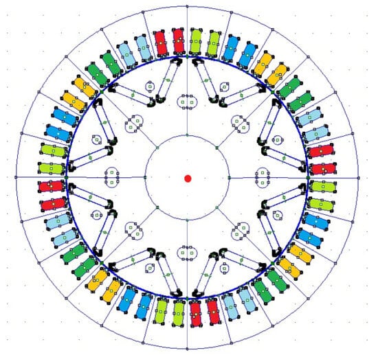
Figure 1.
Used permanent magnet synchronous machine (each pair of color shades represents a machine phase).
This synchronous machine was first modeled in Matlab-Simulink, with the parameters shown in Table 1, to recover the various output quantities of the machine: position, speed, and currents flowing through it. This first modeling of the motor, coupled with the modeling of the whole traction chain, allows the recovery of the effective currents transmitted to the machine to reach a certain speed and torque set point. This modeling was carried out using the Simscape library of Matlab-Simulink. The second 2D modeling, this time using finite elements, was then carried out. This model receives as input the currents calculated for each operating point in the first model and returns the characteristic quantities of the machine for each elementary volume of the model.

Table 1.
Parameters of the model of the machine.
The geometry used for the 2D finite element modeling in Matlab is shown in Figure 2. It shows only one-quarter of the synchronous machine. The results of this paper consider the whole machine by using the symmetry axes of the machine. In the end, a 2D model of the machine is chosen for reduced computation time. The FEM problem is modeled by solving Maxwell’s equations on the mesh defined above. The torque values of the electric machine are also calculated using Maxwell’s tensor method. For finite element modeling, the magnetic material used in the machine must be characterized. These magnetic characteristics of the stator and rotor are obtained through the characterization of the laminations used in the motor studied by the SATIE laboratory (see Figure 2).
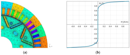
Figure 2.
Geometry and mesh of the studied machine (a) and normalized anhysteretic curve of the studied MSAP sheets (b).
Several Epstein strips of approximately the same thickness as the machine and an excitation coil will allow the measurement of the magnetic field and the flux density in the sample as a function of the input currents. Finally, the experiments carried out allowed the acquisition of an average anhysteretic curve thanks to the calculation of the average of the rising and falling curves of the cycles found.
3. Machine Control Model
The drive train modeled in Matlab-Simulink has, as inputs, a motor torque and speed command, calculated from a road cycle and by applying a road law adapted to the morphology and characteristics of the vehicle. The machine, on the command, imposes a current to the inverter and to the battery, both included in the model, and sends back an adapted voltage. Figure 3 presents the effective modeling scheme, common to the two studied architectures.

Figure 3.
Modeling scheme for architecture (a) and field-oriented control of the machine (b).
The control of the synchronous machine is performed using a field-oriented control. The Park transform substitutes the rotating three-phase vectors () into two vectors in a fixed reference frame (). Speed and torque controls are included in the whole control loop. In the speed loop, a conventional PI controller is used. The torque control is done through the double control of the currents in the Park domain. Figure 3b presents a schematic diagram of this double regulation for the torque. Several control strategies can be applied: the MTPA (maximum torque per ampere) strategy to maximize torque per Ampere or the ML (minimum losses) strategy to minimize Joule losses. For the MTPA control strategy, the current equations in the Park domain are those presented in Equation (1), with the permanent magnet flux linkage, and the inductance values of the direct and quadrature axes and and the direct and quadrature axis currents.
Once these equations are implemented, the control is achieved for these current values in the Park domain and will thus result in the values of input currents to the machine that will maximize the value of torque per ampere.
4. Conversion Structures
The synchronous machine must receive sinusoidal currents in a steady state. For the classic architecture, the aim here is to create square-wave voltage signals using pulse width modulation (PWM) [13]. A typical three-phase inverter consists of several switching cells receiving control signals from the PWM block.
The creation of a sine wave voltage can also be achieved by combining several switching battery cells in series. In this way, a multilevel output voltage is obtained, similar to an analog-to-digital conversion of a sine signal. The IBIS architecture, developed within Stellantis, has a similar purpose to the multilevel inverter architecture. This architecture makes it possible to achieve a higher output voltage than the voltage withstands of each switch, with the same number of cells in a classical architecture. This IBIS architecture is shown in Figure 4. It also offers greater modularity and more precise control than the conventional architecture. This architecture is composed of three different independent lines and each line is composed of several battery cells associated with a low-voltage conversion structure. Figure 4 shows two current waves at the output of a conventional inverter and an IBIS architecture for one phase. The magnitude of the chopping effect depends on the chosen operating point: a higher speed implies a higher frequency, and a higher torque demand implies a higher current magnitude.
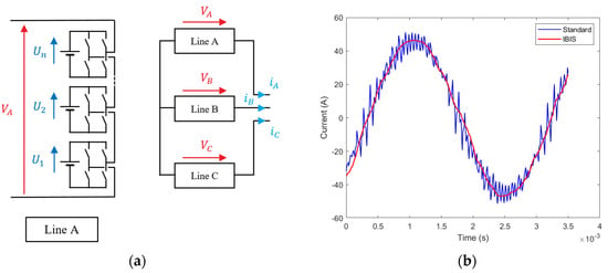
Figure 4.
Scheme of the IBIS architecture (a) and inverter outputs for the standard and IBIS structure for an arbitrarily chosen operating point (15 Nm, 5216 rpm) (b).
The above results were simulated using the acausal modeling of the electric drive train in Simulink. The various conversion stages were modeled using switching blocks and the storage function using Simulink elementary blocks. The modeling takes into account the various losses in the switches and a first rough estimate of the losses in the machine. The aim here is to obtain a current profile that can be used in the FEM modeling of the machine.
5. Road Cycles
A conventional approach to electrical machine design is to calculate the efficiency of the machine for a given operating point [14]. This results in lower efficiency for variable speed operation and, therefore, the oversizing of the components, which leads to higher costs. On a road cycle, a vehicle will be loaded on a set of operating points. To increase the total efficiency of the powertrain, the optimal method would be to design an electric machine that minimizes the losses over all the operating points present in a given road cycle. This method has the disadvantage of a long calculation time, which is a direct consequence of the number of operating points present in a road cycle.
Another approach, already developed and used in [4,14,15,16], is to design an electric machine design taking into account the nominal (Tn, Ωn) and maximum (Td, Ωd) operating points of the machine. The operating points of the road cycle are then divided into several operational areas and represented by centers of mass, weighted by the number of points within the area. The method of calculating the barycenters implies an error in the calculated energy loss [4]. The energy losses are calculated by an analytical model for all operating points and the different barycenters. The relative error over the whole cycle is minimal and will therefore allow faster calculations for the acquisition of losses in the engine over the whole cycle.
For this study, the road cycle used will be the WLTC (Worldwide harmonized Light vehicles Test Cycles). The barycenter method will be used for this cycle, and the barycenter reduction is presented in Figure 5. The WLTC cycle is a procedure that considers all the types of routes taken by the vehicles (city, road, expressway, motorway). The dashed lines correspond to the characteristics of the electrical machine.
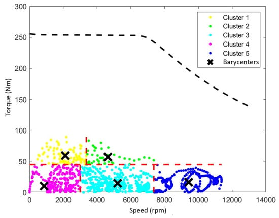
Figure 5.
Barycenters of the WLTC cycles.
6. Losses in the Machine
The losses in an electrical machine can be classified into several groups: the mechanical losses, due to friction and the speed of the machine, the electrical losses in the windings located in the slots of the machine stator (copper losses, composed of AC and DC losses [17]), and the magnetic losses in the various ferromagnetic parts of the electric motor (iron losses), which are divided into eddy current losses and hysteresis losses. The losses in the magnets are neglected here. In this study, the estimation of magnetic and electrical losses will be discussed.
6.1. Calculation of Iron Losses
The calculation of the iron losses is based on the use of the FEMM model of the machine presented or the finite element model in Matlab [18,19]. This machine model is fed by the instantaneous currents, taking into account the presence of the inverter. By proposing a spatial discretization of the motor according to its geometry, the value of the flux density can be determined everywhere and with a consequent computing power, which is necessary in order to have a temporal representation of the flux density in the motor for some periods of the steady state. The flux density in the machine is presented in Figure 6.
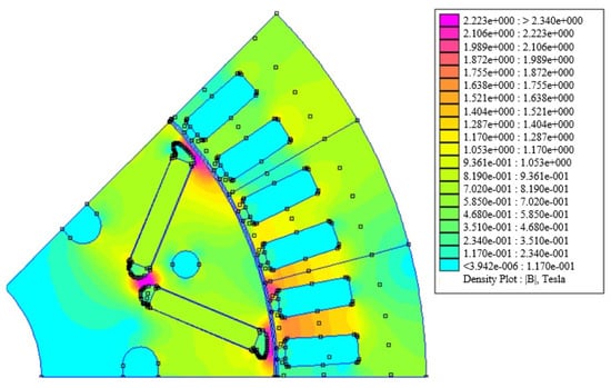
Figure 6.
Flux density (T) in the machine without load.
After recovering the flux density data with a spatial and temporal discretization, the goal is to apply the Fourier transform. The flux density data are then discretized in space and the frequency domain. By removing the computational noise induced by the numerical errors of finite element computations, the entire frequency spectrum can be used. Here, the computations will stop shortly after 10 kHz the frequency, around which the effects of inverter switching occur. A strong assumption is made in this subject: the linearity of the calculation of losses in the frequency domain. Thus, the decomposition of flux densities into Fourier series will be carried out in order to have a frequency representation of the flux density in ferromagnetic materials [20,21,22].
Then, a formula for calculating the iron losses for each harmonic will be applied. As the aim is to compare the two structures presented, the error in the iron losses due to this method of calculation will not be a problem. Indeed, it is the difference in losses between the two structures that is examined. We can nevertheless add that on not too high frequencies and signals with few harmonics, the assumptions on the loss calculations seem to be appropriate [23,24]. Finally, all these contributions will be summed up to obtain an estimate of the iron losses in the machine. This approach is intended to provide a first estimate without taking into account the effects of minor cycles in the material [25]. The formula summarizing the calculation method used is shown as Equation (2), with the losses , depending on the frequency and the flux density, summed up for all the frequency and all the elementaries volumes.
The volumetric iron losses in an element for a given frequency in the Fourier decomposition are summed by frequency and for all elements, weighted with the volume of the element, to obtain the total iron losses in the machine. Mapping is applied to the frequency-domain representation of the flux density signals at different locations, and then each volume loss value is correctly associated with its spatial discretization. Using the Steinmetz formula, the presented mapping can be split into three parts, corresponding to the two types of iron losses: hysteresis losses and eddy current losses. The Steinmetz formula is given in Equation (3), where , , and are constants determined experimentally through mapping. The term proportional to the frequency is related to the static coercive field Hc, the second and third are dependent on the geometry of the material. The first term represents the hysteresis losses and the second is the eddy current losses.
The mapping is thus applied to the frequency-domain representation of the flux density signals at different locations, and then each volume loss value is correctly associated with its spatial discretization. In the end, we obtain values of the iron losses in the motor as a function of the harmonic frequencies present in the magnetic flux density of the motor, as presented in Figure 7.
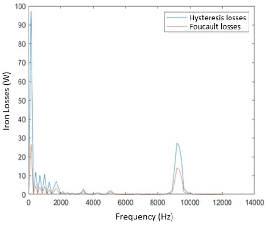
Figure 7.
Frequency losses in the machine for a PWM frequency of 10 kHz (60 Nm, 2 000 rpm).
The multilevel inverter structure seems to offer lower iron loss values than the conventional inverter. Indeed, the harmonic content of the current and flux density quantities is richer in the case of the conventional inverter than in the multilevel inverter. The deviations vary according to the operating point and are reduced with an increase in speed.
6.2. Calculation of Copper Losses
The calculation of the copper losses can be carried out with FEMM software, and the model used is presented above. By using FEMM, the AC component of copper losses in the slots can be only estimated with sinusoidal currents for one position of the rotor. In the same way as for the iron losses, a model directly under Matlab is used to carry out the finite element calculations. A magneto-static resolution and a simplified geometry in a magneto-dynamic resolution are coupled [26]. For this loss calculation, two different meshes are used. Firstly, a mesh for the magneto-static calculation, which allows the calculation of the flux density and the magnetic vector potential in the whole motor, is used. This is the same as the one for the calculation of the iron losses. Then, a second mesh, presented in Figure 8, is built to carry out a magneto-dynamic calculation only in a notch. The calculated magnetic vector potential is applied as a boundary condition. For this study, the notches will have only two conductors. The finite element quantities are interpolated between the two meshes of different sizes (with the mortar method), from the full mesh to the slot mesh (it is necessary to have a more accurate mesh in the slot than in the whole electrical machine).

Figure 8.
Slot mesh of the machine (a) and current density in slot (b).
With this method, the current density and thus the copper losses in the conductors can be calculated by taking into account the flux density and magnetic field maps in the machine with a reduced calculation time. The current density in a slot is shown in Figure 8. The magneto-dynamic calculation provides maps of the current density in the slot and thus calculates the distribution of copper losses (AC and DC). In the end, the calculation provides an estimate of the copper losses in the entire motor, taking into account the depth of the motor and the various simplifications due to magnetic symmetries.
6.3. Comparison of Losses
Finally, the efficiency and the different losses in the machine can be summarized in Table 2 and Table 3 according to the different barycenters of the WLTC road cycle. The barycenter mapping effectively shows the advantage of the multilevel architecture compared to the classical inverter architecture. The calculated efficiency in the case of a multilevel architecture is higher than in the conventional case, whatever the barycenter chosen. The harmonic richness of the currents leaving the conventional inverter increases the losses in the motor.

Table 2.
Iron losses comparison in cycle.

Table 3.
Copper losses comparison in cycle.
For the different barycenters chosen earlier, the copper loss values presented in Table 3 are obtained. As for the iron losses, the differences in copper losses between the structures vary according to the operating point. The multilevel inverter structure is the most efficient in terms of copper losses.
7. Experiments
In this section, an experimental protocol for simulating the operation of an electric vehicle powertrain will be presented and several experiments will be carried out in order to validate the modeling presented previously. As shown in Figure 9, the test bench consists of:
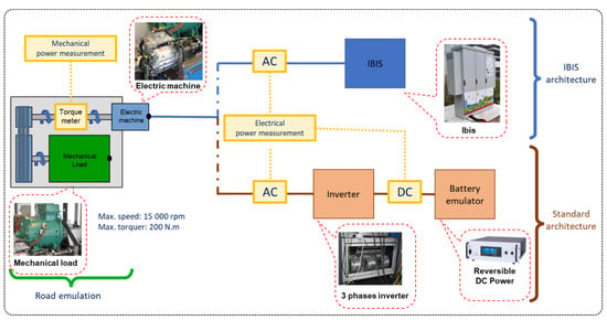
Figure 9.
Electric vehicle powertrain test bench in use.
- -
- A load machine to emulate driving conditions.
- -
- An industrial rectifier and inverter unit for creating the three-phase mains voltage of the load machine.
- -
- A permanent magnet synchronous machine, named M0 (60 kW in nominal working), and its cooling system.
- -
- The IBIS battery and its cooling system.
- -
- A torquemeter (measuring torque and speed) and a wattmeter (measuring electrical power).
- -
- Two cells for controlling and supervising the IBIS battery, the M0 machine and the charging machine.
- -
- A Brusa inverter.
- -
- A 90 kW reversible power supply.
All these elements emulate the operation of a standard electric vehicle powertrain and an IBIS powertrain. The M0 machine is torque-controlled by the control cell, which sends a three-phase voltage setpoint to the IBIS battery or standard battery emulator. The speed of the charging machine is controlled by the second supervision cell.
The purpose of the tests is to measure the efficiency of the M0 machine, which will be defined by the following equation, where define the motor torque, the speed of rotation of the machine, and the electrical power at the input to the machine.
The test is carried out at one operating point (torque, speed) for each type of drive train, i.e., standard and IBIS. The electrical power is measured by a wattmeter and the torquemeter is used to measure the torque and speed of rotation of the electrical machine, which gives us the mechanical power output of the machine. The efficiency is then calculated using relationship (4).
Finally, at a few operating points, the difference in efficiency between the two types of drive train was measured and compared with the simulation results. Table 4 presents these experimental results.

Table 4.
Comparison of profit between experimental and simulated electric chain.
These results show a static error in the efficiency gain between the experimental and simulated electrical chains. On these few operating points, we observe a greater difference in efficiency for the high-speed and low-torque points. The operating points at high torque have a smaller difference. This difference can be explained by the fact that certain losses in the machine are not taken into account in the simulated model. The error may come from the estimation of the iron loss parameters. Assembly or machining constraints on the machines, or the effect of the coil heads, have not been taken into account. The electrical machine receives current either from the IBIS battery or from a complex system consisting of a converter and a battery emulator. Finally, these experimental results also show the difference in yield between a conventional architecture and an IBIS architecture.
8. Conclusions
In this study, a finite element modeling of a synchronous machine with permanent magnets of a classic car was performed on Matlab. This modeling, which was quite precise and meshed under FEMM, allowed a series of magneto-static and magneto-dynamic calculations with the aim of acquiring the magnetic and electrical quantities. The computation of electromagnetic losses in the machine has been realized. These calculations were carried out on a set of operating points representing, through the calculation of the barycenters of operating points of a classic road cycle of an electric vehicle (WLTP). This work has allowed the development of a complete model of a drive train coupled with a fast method for calculating losses in a synchronous machine. This method makes it possible to highlight the impact of the conversion structure on these losses.
In the end, all the calculations made in this study show a clear advantage of the IBIS architecture (which can be likened to a multilevel architecture) in terms of losses in the machine. The advantage of this architecture in the cycle is shown in Table 4. Also, the energy lost on the cycle can be calculated by weighting each barycenter by the number of operating points it represents. Table 5 shows the simulated road cycle performance gains of the architecture presented.

Table 5.
Efficiency comparison in cycle.
The modeling of magnetic and electrical phenomena in the electric machine could in the future be completed using mechanical, acoustic, and thermal approaches, allowing a comparison of more advanced architectures. Another improvement method could take into account the different machine modes (motor and generator). Future studies could also focus in detail on the calculation methods and their optimization in order to reduce calculation times, especially in the case of finite element calculations (interpolation methods for example). At high frequencies, the loss calculation model can be less precise and could also be improved. The last assumption regarding the limits of this work concerns the model of command, which can differ from one type of structure to another and may be different in the future.
Author Contributions
Conceptualization, R.J. and G.K.; methodology, R.J. and G.K.; software, G.K. and A.L.; validation, F.R. and C.M.; investigation, R.J. and G.K.; resources, G.K. and A.L.; data curation, G.K. and A.L.; writing—original draft preparation, R.J.; writing—review and editing, R.J., G.K., A.L., F.R. and C.M.; visualization, R.J. and G.K.; supervision, G.K. and F.R.; project administration, F.R. and C.M.; funding acquisition, G.K. and F.R. All authors have read and agreed to the published version of the manuscript.
Funding
This paper is part of the IBIS project, which is funded by ADEME (French Agency for the Ecological Transition) through the program “Investissement d’Avenir (PIA)”.
Data Availability Statement
The data are not publicly available due to confidentiality.
Conflicts of Interest
The authors declare no conflict of interest.
References
- Ben Ahmed, H.; Bethoux, O.; Cizeron, A.; Hoang, E.; Juton, A.; Laboure, E.; Mercier, A.; Monmasson, E.; Ojeda, J.; Queval, L.; et al. Electric Traction Chain with Segmented Power Supply. In Proceedings of the 2021 23rd European Conference on Power Electronics and Applications (EPE’21 ECCE Europe), Ghent, Belgium, 6–10 September 2021; IEEE: Toulouse, France, 2021; pp. 1–10. [Google Scholar] [CrossRef]
- Cai, W.; Wu, X.; Zhou, M.; Liang, Y.; Wang, Y. Review and Development of Electric Motor Systems and Electric Powertrains for New Energy Vehicles. Automot. Innov. 2021, 4, 3–22. [Google Scholar] [CrossRef]
- Mazali, I.I.; Daud, Z.H.C.; Hamid, M.K.A.; Tan, V.; Samin, P.M.; Jubair, A.; Ibrahim, K.A.; Kob, M.S.C.; Xinrui, W.; Talib, M.H.A. Review of the Methods to Optimize Power Flow in Electric Vehicle Powertrains for Efficiency and Driving Performance. Appl. Sci. 2022, 12, 1735. [Google Scholar] [CrossRef]
- Krebs, G.; de Cecco, E.; Marchand, C. Design approach of an axial flux motor for electrical powertrain vehicle. In Proceedings of the 2012 XXth International Conference on Electrical Machines, Marseille, France, 2–5 September 2012. [Google Scholar]
- Aghabali, I.; Bauman, J.; Kollmeyer, P.J.; Wang, Y.; Bilgin, B.; Emadi, A. 800-V Electric Vehicle Powertrains: Review and Analysis of Benefits, Challenges, and Future Trends. IEEE Trans. Transp. Electrif. 2021, 7, 927–948. [Google Scholar] [CrossRef]
- Jung, C. Power Up with 800-V Systems: The benefits of upgrading voltage power for battery-electric passenger vehicles. IEEE Electrif. Mag. 2017, 5, 53–58. [Google Scholar] [CrossRef]
- Busquets-Monge, S.; Alepuz, S.; García-Rojas, G.; Bordonau, J. Electric Vehicle Powertrains with Modular Battery Banks Tied to Multilevel NPC Inverters. Electronics 2023, 12, 266. [Google Scholar] [CrossRef]
- Roemer, F.; Ahmad, M.; Chang, F.; Lienkamp, M. Optimization of a Cascaded H-Bridge Inverter for Electric Vehicle Applications Including Cost Consideration. Energies 2019, 12, 4272. [Google Scholar] [CrossRef]
- Rumpf, K.; Naumann, M.; Jossen, A. Experimental investigation of parametric cell-to-cell variation and correlation based on 1100 commercial lithium-ion cells. J. Energy Storage 2017, 14, 224–243. [Google Scholar] [CrossRef]
- Roy, F. IBIS (Intelligent Battery Integrated System). ADEME, PSA GROUPE. 2019. Available online: https://librairie.ademe.fr/mobilite-et-transport/683-ibisintelligent-battery-integrated-system.html (accessed on 2 December 2023).
- CEA. Battery Having a Brick Architecture Including Cells Arranged in Series or in Parallel. EP2735038(B1), 4 August 2021. [Google Scholar]
- Mayet, C.; Labrousse, D.; Dittrick, A.; Revol, B.; Bkekri, R.; Roy, F. Simulation and Control of a New Integrated Battery System for Automotive Applications. In Proceedings of the PCIM Europe Digital Days 2021; International Exhibition and Conference for Power Electronics, Intelligent Motion, Renewable Energy and Energy Management, Online, 3–7 May 2021; pp. 1–6. [Google Scholar]
- Holmes, D.G.; Lipo, T.A. Pulse Width Modulation for Power Converters: Principles and Practice; John Wiley: Hoboken, NJ, USA, 2003. [Google Scholar]
- Kaloun, A.; Brisset, S.; Ogier, M.; Ahmed, M.; Vincent, R. Comparison of Cycle Reduction and Model Reduction Strategies for the Design Optimization of Hybrid Powertrains on Driving Cycles. Energies 2021, 14, 948. [Google Scholar] [CrossRef]
- André, J.M.; Lacour, S.; Hugot, M.; Olah, Z.; Journard, R. Impact of the Gearshift Strategy on Emission Measurements—Artemis 3142 Report; Report No. LTE 0307; INRETS: Bron, France, 2003. [Google Scholar]
- Cardoso, J.F.; Chillet, C.; Gerbaud, L.; Belhaj, L.A. Electrical Machine Design by optimization for E-motor Application: A Drive Cycle Approach. In Proceedings of the 2020 International Conference on Electrical Machines (ICEM), Gothenburg, Sweden, 23–26 August 2020; IEEE: Toulouse, France, 2020; pp. 2514–2519. [Google Scholar] [CrossRef]
- Hebala, A.; Nuzzo, S.; Connor, P.H.; Volpe, G.; Gerada, C.; Galea, M. Analysis and Mitigation of AC Losses in High Performance Propulsion Motors. Machines 2022, 10, 780. [Google Scholar] [CrossRef]
- Henneron, T.; Clenet, S.; Cros, J.; Viarouge, P. Evaluation of 3-D Finite Element Method to Study and Design a Soft Magnetic Composite Machine. IEEE Trans. Magn. 2004, 40, 786–789. [Google Scholar] [CrossRef]
- Le Menach, Y.; Clenet, S.; Piriou, F. Determination and utilization of the source field in 3D magnetostatic problems. IEEE Trans. Magn. 1998, 34, 2509–2512. [Google Scholar] [CrossRef]
- Krings, A.; Soulard, J. Overview and Comparison of Iron Loss Models for Electrical Machines. J. Electr. Eng. 2010, 10, 162–169. [Google Scholar]
- Moses, A. Effects of magnetic properties and geometry on flux harmonics and losses in 3-phase, 5-limb, split-limb, transformer cores. IEEE Trans. Magn. 1987, 23, 3780–3782. [Google Scholar] [CrossRef]
- Wan, X.; Li, Y.; Li, J.; Liu, C.; Zhu, J. Orthogonal decomposition of core loss along rolling and transverse directions of non-grain oriented silicon steels. AIP Adv. 2017, 7, 056651. [Google Scholar] [CrossRef]
- Yan, W.; Chen, H.; Liu, Y.; Chan, C. Iron loss and temperature analysis of switched reluctance motor for electric vehicles. IET Electr. Power Appl. 2020, 14, 2119–2127. [Google Scholar] [CrossRef]
- Moses, A.; Shirkoohi, G. Iron loss in non-oriented electrical steels under distorted flux conditions. IEEE Trans. Magn. 1987, 23, 3217–3220. [Google Scholar] [CrossRef]
- Zhao, H.; Ragusa, C.; de la Barriere, O.; Khan, M.; Appino, C.; Fiorillo, F. Magnetic Loss Versus Frequency in Non-Oriented Steel Sheets and Its Prediction: Minor Loops, PWM, and the Limits of the Analytical Approach. IEEE Trans. Magn. 2017, 53, 2003804. [Google Scholar] [CrossRef]
- Al Eit, M.; Dular, P.; Bouillault, F.; Marchand, C.; Krebs, G. Perturbation Finite Element Method for Efficient Copper Losses Calculation in Switched Reluctance Machines. IEEE Trans. Magn. 2017, 53, 7202004. [Google Scholar] [CrossRef]
Disclaimer/Publisher’s Note: The statements, opinions and data contained in all publications are solely those of the individual author(s) and contributor(s) and not of MDPI and/or the editor(s). MDPI and/or the editor(s) disclaim responsibility for any injury to people or property resulting from any ideas, methods, instructions or products referred to in the content. |
© 2023 by the authors. Licensee MDPI, Basel, Switzerland. This article is an open access article distributed under the terms and conditions of the Creative Commons Attribution (CC BY) license (https://creativecommons.org/licenses/by/4.0/).