Article

FCH HVAC Honeycomb Ring Network—Transition from Traditional Power Supply Systems in Existing and Revitalized Areas

1
Faculty of Civil Engineering and Architecture, Lublin University of Technology, Nadbystrzycka 40, 20-618 Lublin, Poland
2
Sanitary Engineer “WAKAD”, 20-250 Lublin, Poland
3
Institute of Agrophysics, Polish Academy of Sciences, Doświadczalna 4, 20-290 Lublin, Poland
*
Author to whom correspondence should be addressed.
Energies 2023, 16(24), 7965; https://doi.org/10.3390/en16247965
Submission received: 8 November 2023 / Revised: 28 November 2023 / Accepted: 4 December 2023 / Published: 8 December 2023

Abstract

:
This paper discusses the application of a new honeycomb FCH HVAC (Free Cooling and Heating System, Heating, Ventilation, and Air Conditioning) ring network technology that reduces the primary energy consumption in existing infrastructure. The aim of the research is to evaluate the cost-environmental viability of upgrading the technical infrastructure and moving from traditional to newly designed green systems built on renewable energy sources. The results show that the energy capacity stored in groundwater is equivalent to 65% of building demand, resulting in a 60% reduction in CO2 emissions compared to a traditional HVAC system. The solution reduces the consumption of natural resources by using renewable energy sources with horizontal heat exchangers arranged in independent ring configurations.

1. Introduction

The HVAC (Heating, Ventilation, and Air Conditioning) system is currently the best mechanical system for buildings to ensure thermal comfort for occupants and indoor air quality [1]. The development of urban areas relies on access to water, heat and power, which determine an adequate standard of living of a given community [2,3,4]. In the context of the topic of environmentally friendly construction and cities of the future, we think of green housing, which is becoming a standard in modern cities [5]. People living in such green areas usually recognize major benefits from using environmentally friendly construction materials with a very low carbon footprint or other solutions that improve living conditions in housing estates, districts, and cities as a whole [6]. The growing awareness of the profound impact of the correct ecology on the lives of all people, and older people and children in particular, raises expectations towards investors and developers [7]. The focus is primarily on protecting the environment, reducing CO2 and the carbon footprint, and in the long-term, protecting the human species itself [8,9]. For these reasons, recently, there have been more studies on modern, environmentally friendly solutions for erecting new buildings, which can, above all, significantly reduce energy consumption [10,11]. For several years, architects have introduced environmentally friendly solutions based on, e.g., solar panels, wind turbines, green roofs, and green walls, but these solutions do not reduce the energy consumption significantly [12,13]. It is also important to note the recently popular heat pumps, which used to be commonly installed until comprehensive studies were conducted, but with new PE H + W measures introduced, under the current Technical Requirements, these are not so attractive from technical and economic points of view, and in terms of PE consumption, these are similar to HVAC systems powered directly with electricity [14].
The current situation in the energy market creates opportunities for low-carbon energy to play an important role in building modern and environmentally friendly economies [15,16]. The enormous power of energy stored in groundwater and the independence of this energy from external factors, as well as a very low carbon footprint, make these technologies the undisputed leader in CO2 reduction in Poland and the world [17]. This power is much greater than that from PV cells or wind [18,19].
An example of energy consumption reduction is the program “Research aimed at obtaining high quality of air in architecture and urban planning”, which has been implemented since 2018 by the team of the Institute of Architectural Design at the Department of Contemporary Architecture of the Faculty of Civil Engineering and Architecture, Lublin University of Technology. The research included such buildings as the Old Shopping Center Public Utility Building with modernized “Targówek” 15,000 m2 EL heating in Warsaw; the Shopping Center in Mielec “Navigator” 33,000 m2; The Potocki palace and Park Complex in Radzyń Podlaski 2500 m2; the Eastern Innovation Center of Architecture in Lublin “WICA” 5000 m2; The Sobieski Family Palace in Lublin; and Marshal Piłsudski’s “Milusin” Museum 1750 m2 in Sulejówek near Warsaw.
It is expected that in 2050 more than 60% of the global population will live in cities. Today, according to European Commission statistics, in the EU, buildings consume up to 40% of the energy they produce, so they are responsible for about 35% of greenhouse gas emissions [14,20].
For the HVAC type systems in question, various techniques must be implemented to effectively and significantly improve their energy efficiency and reduce their environmental impact [21]. Various optimization efforts have long been undertaken to improve the energy consumption rates of these systems [22]. The article presents contemporary solutions of combined structures of HVAC systems responsible for comfort and indoor air quality. The original authors research on modification of traditional HVAC technology in the form of rings called the FCH HVAC honeycomb is presented. The authors’ research shows that the use of the honeycomb effectively reduces the energy demand of HVAC systems. The innovative solutions of HVAC systems are then presented, supported by examples of an already completed residential development using this technology. The analysis was conducted for residential buildings with combined and jointly operating HVAC technologies. The main purpose of using this technology was to reduce the cost per energy requirement for residential complexes. At the same time, studies show that using the patented technology also significantly reduces CO2 emissions. The research presents both a description of the HVAC honeycomb and a comparison with it with standard HVAC technology. Reference is also made to traditional solutions and their subsequent effects in energy demand and CO2 emissivity. Solutions of this type enable the introduction of new control strategies and decentralization of stored thermal energy along with the possibility of thermally using a large amount of low-temperature waste heat available in urban areas. The interest in these networks is documented by the fact that at least three installations of this type have been launched in Europe in the last decade [23].
The authors discovered no literature reports on the application of the described solution, either as a design concept or, more importantly, as a realized investment.
Therefore, it can be said that this is the first work with a description of a novel approach to the HVAC concept using honeycomb building solutions and connections. The proposed and described solution is innovative and original, and moreover, an energetically, and thus, economically competitive approach to traditional HVAC systems.
Today’s HVAC technology, which is used worldwide, has a huge impact on reducing CO2 emissions and energy consumption. It should therefore be developed, cascaded, and modified. This article presents an improvement of this technology by sourcing chilled water and supplying several facilities simultaneously from a single source. The FCH HVAC technology connects several facilities together through a network of interconnected buildings in order to use energy as efficiently as possible through energy recovery.

2. Materials and Methods

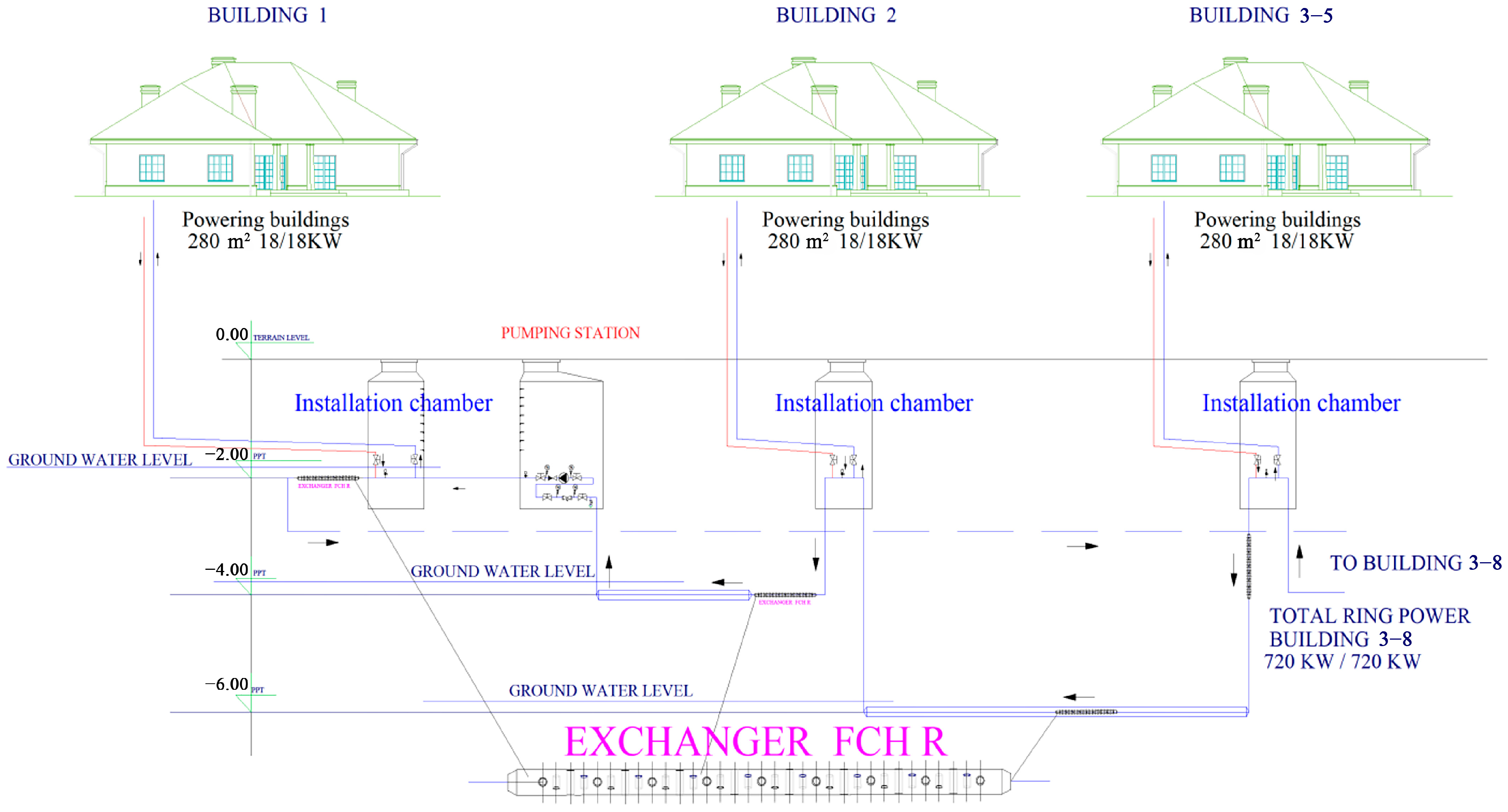
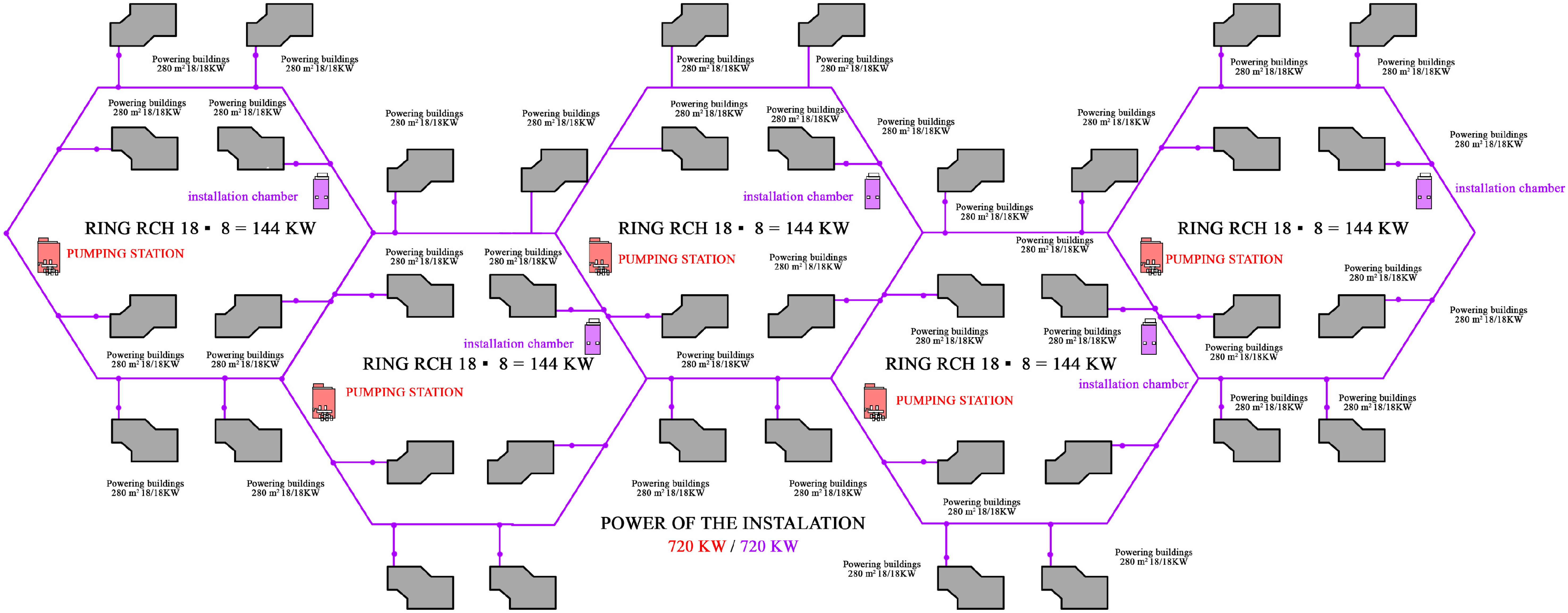
2.1. FCH HVAC Technology

As researched in many scientific publications, HVAC systems can be a versatile tool to effectively reduce the energy demand of buildings using renewable energy. Continuous improvement and application of this technology is therefore of significant importance to the global environment [15]. The adopted research method is based on the use of the above technology in the designed layout of residential buildings. Calculations related to this system clearly indicate the desirability of further activities developing this technology. The purpose of using FCH technology is to extract energy for heating and cooling from groundwater. It is delivered by glycol piping to the FCH HVAC unit, heating or cooling the air circulation to the desired temperature. This significantly reduces the primary energy consumption and also CO2 emissions. Traditional HVAC systems draw thermal energy from municipal grids or other sources, and energy for cooling from chillers. These chillers produce electricity by obtaining parameters: supply of 7 °C and return of 12 °C. In contrast, with FCH technology, the energy required for system operation comes 80% from groundwater, and the remaining 20% is supplemented from other sources. The conducted research described in this chapter presents a new approach to greening and reducing CO2 emissions not only in industrial and residential buildings, but also in historic buildings. The primary objective of this solution is to extract energy from the FCH HVAC network from the annular groundwater system [19,24] and to feed the obtained energy directly into the HVAC systems in civil, industrial, and historic buildings [25]. As shown later in the article, the expected efficiency of such systems is more than 50% of the demand for a neighborhood, district, or city.
Figure 1 shows the distribution of temperatures in ground water at a depth of up to 10 m or more. As can be seen, the temperature stabilizes at about 10 °C. The authors show what this means for the power calculations for civil structures using the example of a study of a working FCH system in Poland.
The presented graph (Figure 2) shows constant groundwater parameters throughout the year. This parameter is the basis of the installation; FCH HVAC R allows us to change the installation in regions of lower power demand. We must remember that estates of small houses have little energy demand, and for these investments, it is enough to obtain heat and cold from horizontal installations in a honeycomb system on site without the need to build large networks and substations. The power of small buildings, estimated at approximately 18 kW, will be transferred to the ground over a length of approximately 5 m, so this alternative method of obtaining energy is attractive not only in terms of operating costs but also in terms of investment costs. The aim of this solution is also to reduce CO2 emissions and the very short distribution of energy to consumers. These installations are also an alternative to urban networks which, over hundreds of kilometers, lose hundreds of kW on heat distribution, which the society and the environment pay for.
The presented chart (Figure 2) shows the zones in which it is worth installing horizontal FCH HVAC R installations due to the implementation costs.
It should be remembered that with each shallowing of the installation, energy is lost in summer and winter, so it is worth maintaining the recommended level of 4.5 m, which is feasible in all conditions and will provide us with the parameters at these depths shown in the chart Figure 2. The installations are innovative and secure a more than 50% reduction in CO2 emissions. The parameters of the installation in the range of 3–6 m in the summer are 10.5 °C to 11.5 °C and in the winter, they are 8.5 °C to 9.5 °C.
The basis of the FCH HVAC installation are horizontal exchangers which are made in the horizontal part in dry zones of PE pipes whose thermal conductivity coefficient is 0.4 W/mK, while in groundwater zones, the exchangers are made of acid steel pipes with a coefficient of 50 W/mK.
The analysis of the differences in thermal resistance of the partition is given as (Equation (1))
R = w a l l   t h i c k n e s s c o n d u c t i o n   c o e f f i c i e n t m 2 K W
The results for PE and steel are, respectively, as follows:
PE—0.0036 [m]/0.4 [W/mK] = 0.009 [m2K/W]
Steel—0.0036 [m]/50 [W/mK] = 0.000073 [m2K/W]
In the thermal resistance calculation, the thermal resistance of the layer of water adjacent to the pipe should be also taken into account. However, these are constant values and do not affect the performance enough, so they are omitted at this stage. Next, the heat transfer coefficient can be calculated as (Equation (2))
U = 1 R W m 2 K
for PE and steel is, respectively:
PE—1/0.009 = approx. 111 [W/m2K]
Steel—1/0.000073 = approx. 13700 [W/m2K].
The designed FCH installations in a honeycomb arrangement are made of acid steel with a factory length of 6 m. The pipe area in one well is the pipe circumference—Π × pipe diameter = Π × 0.063 = 0.198 m; (ii) pipe area—0.198 m × 6 m = approx. 1.19 m2.
Determination of heat released or cold taken (Equation (3)) in by one section of 6 m long pipes, assuming a temperature difference of 5 K, was determined, respectively, as follows:
H e a t   r e l e a s e d   o r   C o l d   t a k e n = U · p i p e   a r e a · Δ T W
PE—111 × 1.19 × 5 = 660 W [approx. 0.6 kW], so it is 120 W per meter of cable;
Steel—13700 × 1.19 × 5 = 81515 W [approx. 81.5 kW] − 13.58 kW per meter of cable.
The result at this stage is PE 120 W/m to STEEL 13.58 kW/m, assuming a temperature difference of 5 K, and level 1 K is PE 24 W/m to STEEL 2.72 kW/m, respectively. Further analysis of the installation efficiency, especially the coefficient of the previously mentioned heat transfer resistance for the water layer at the boundary with the wall, will not have a significant impact on the installation efficiency. It is still possible to study the effect of water velocity in the pipe and temperature difference on heat and cold exchange, but this depends on the soil structure and groundwater level, and these analyses should be carried out for specific locations. The presented results allow the design of FCH installations in a ring system.
Basic assumptions for the presented solution of the ring network:
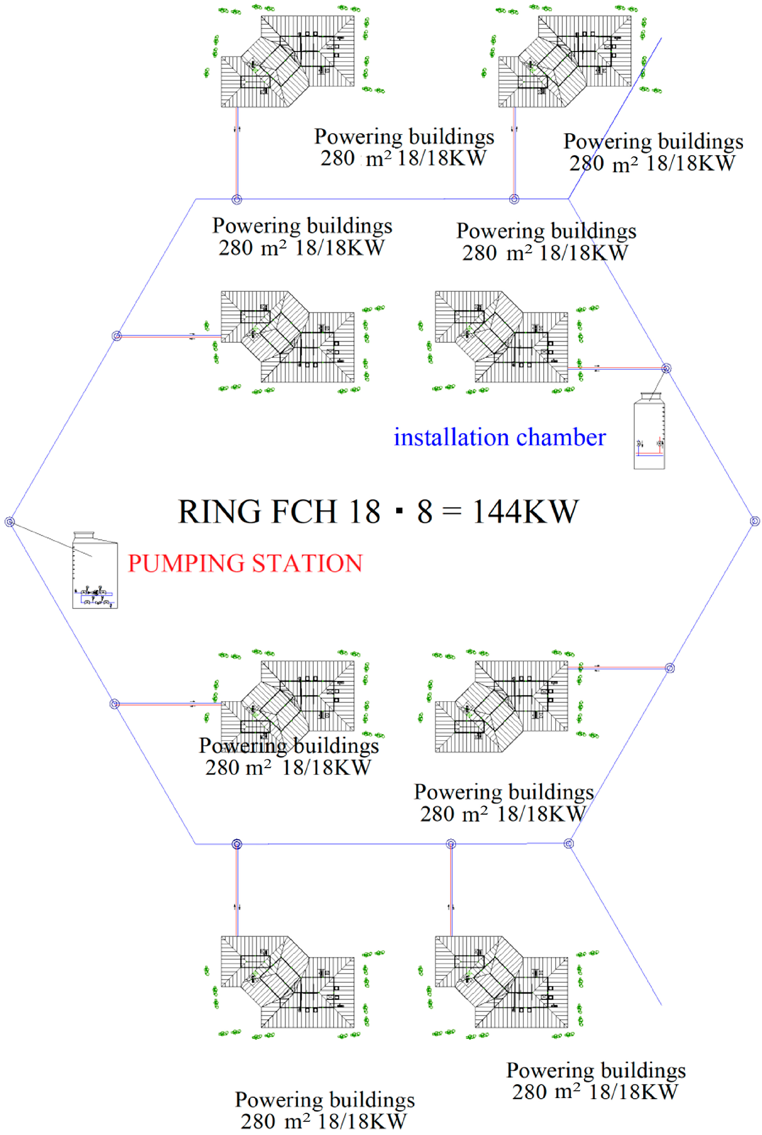
  • A network with independent rings that power 8 buildings with 18 kW each;
  • Distance between manholes and connections to buildings is approx. 20 m;
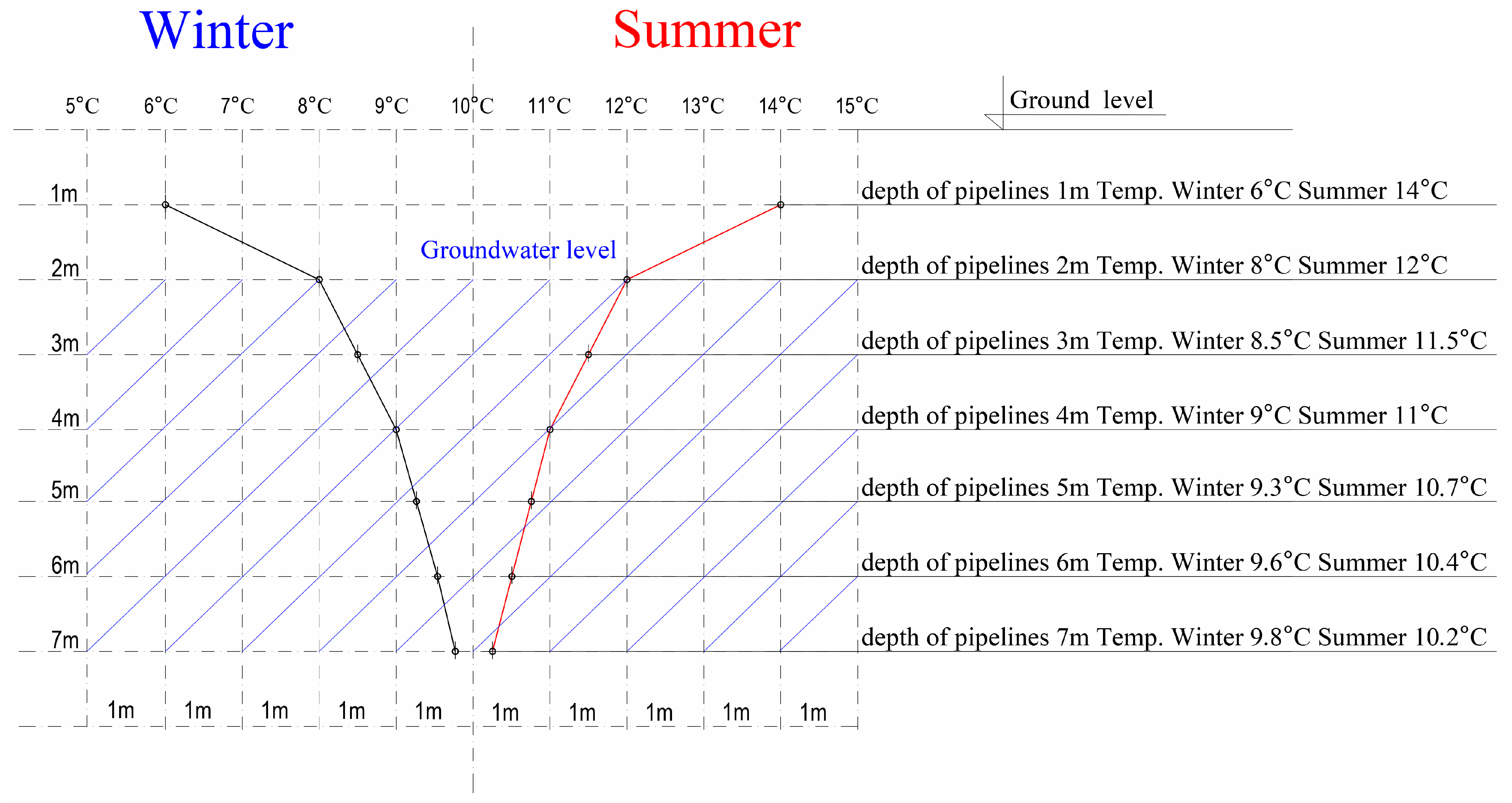
  • Groundwater level 3–6 m below ground level;
  • Depth of the levels approximately 5 m;
  • Expected result at a temperature difference of 2 K.
Horizontal exchangers, acid steel, heat, and cold power transfer to the water and ground is 2.72 kW/m × 2 K = 5.44 kW/mK. The minimum length of the external network for regeneration is 18 kW/5.44 Kw = 3.31 m
Based on published studies [24,26], the authors determined the ability to reduce emissions. The entire installation, as can be seen, is an alternative to large heat networks, gas boilers, and heat pumps and is the only installation that can reduce CO2 emissions by 50%, and with its innovation and practically trace amounts of carbon footprint, it is and will be the only installation in the future which will power small settlements and cities without such expensive municipal networks. These installations are also an ecological opportunity for settlements and population centers located far from cities.
The results in Figure 3 present the stability of the FCH HVAC Mielec system parameters throughout the year.
Building maintenance management is often linked to innovative strategies and sustainability [27]. The power of the system at temp. of −18.3 °C. Figure 4 is from a simplified Building Management System (BMS) [28]. The system is described in Section 2.1. Changing the system of energy consumption from systems limited by the area of the plot, for example, to unlimited spaces that are honeycomb rings, which are mainly installed on common parts, roads, and parking lots at depths of less than 3 m to 6 m below the ground level, resulting in the location below the external networks. Small depths, a simple way of construction, have adapted HVAC systems to lower parameters to give much better results.
Figure 4 shows the energy of ground water (7) with a temperature of 8.6 °C heating the outside air (1) from −11 °C to 6.9 °C (2), after the rotary exchanger is heated to 19.2 °C (3). With such energy, it is possible to maintain indoor temperatures of 22 °C during the winter, where the outside temperature is −11 °C. This is achievable at zero cost and without the use of heat pumps.
Figure 5 shows results of the energy recovery from an FCH system from ground water, with a constant temperature of the input air after heating by the FCH heater. The left-hand side of the figure presents the operation of the system with night breaks, while the right-hand side presents the operation of the system at night, with a view from the BMS FCH unit.

2.2. FCH HVAC System in a Ring Configuration

In HVAC systems, optimization problems are highly constrained and complicated. It is necessary to have an effective optimization method to solve them [29]. It is a system for obtaining ice water from a system installed in ground water for the purposes of air-conditioning and ventilation equipment [30]. An FCH system has a horizontal perforated ice water exchanger located on horizontal pipes that is connected in a ring configuration to retain the honeycomb structure [31]. Ground water from a depth of 5 m below the ground is a natural source of heat and cold, and using it for cooling or heating purposes is using renewable energy that is environmentally friendly, non-invasive, and does not interfere with the natural environment. Deep water at a depth of 10 m has a temperature of 10 °C, which means that the use of aggregators becomes unnecessary. Of course, it is necessary to take into account the external conditions (height of groundwater, direction of tide, etc.), as they determine the performance of the FCH HVAC system.
A typical HVAC unit consumes energy at 605 PA, while the FCH HVAC reduces this to as low as 97 PA at constant airflow resistance.
Energy harvesting is carried out through a single well for the entire system to which the buildings are connected. Currently, installations of this type were based on vertical exchangers mainly using heat pumps. The proposed innovative solution is to use horizontal exchangers. This solution is based on extracting energy from ring systems, which recover energy for consumers in a closed system. Deep water intake reaches deeper into the water table to combine them into a single system that powers the buildings. If one building does not use the accumulated energy and therefore has excess energy, it transfers it to the next in the honeycomb ring system. Entire housing complexes can therefore be served by a single borehole, rather than each one individually as used by ordinary HVAC technology.
Networks of HVAC technologies are effective solutions for replacing traditional methods with renewable energy sources for heating and cooling [32]. Their use and improvement enable further improvements in energy efficiency. Heat generated from cooling can be reused for heating due to the two-way flow of energy. The technology described in this article presents a novel honeycomb network arrangement for the simultaneous heating and cooling of entire housing complexes. The network integrates heat sources and heat sinks at different temperature levels. The more the network is expanded, the higher its efficiency will be.

3. Results and Discussion

The system is installed in a 33,000 m2 structure shopping center in Mielec, the “Navigator”. The results are analyzed and summarized using the BMS. The system has been in operation since 2016.
Basic yearly results/CS3 in Mielec show a constant indoor temperature of 20 °C to 22 °C with outdoor temperatures in winter of −17 °C and in summer of +37 °C. Based on these results, this system can easily be considered environmentally friendly and energy-saving, while also reducing CO2 emissions.
The basis for calculating the FCH HVAC heat output extracted from the groundwater of the Gallery in the Mielec “Navigator” facility is as follows:
-
Area served by FCH HVAC Centrals—33,000.00 m2;
-
Ventilation air supply rate indicator—8 m3/h/m2.
V = 33,000.00 m2 ▪ 8 m3/h = 264,000.00 m3/h = 73.33 m3/s
Q = V · ρ · C p · Δ T   [ k W ]
V—volumetric air flow rate m3/s;
ρ—air density = 1.2 kg/m3;
Cp—specific heat of air = 1.005 kJ/kg·K;
ΔT—difference in the air temperature upstream and downstream of the heater (°C).
The FCH heat recovery capacity (Figure 4①) is Tz= −11.0 °C, and the TFCH behind the heater (Figure 4②) is 6.9 °C.
The tested area is as follows:
Q F C H = 73.33 · 1.2 · 1.005 · 11.0   ° C + 6.9   ° C = 1583.00   k W = 48   W m 2
Heat recovery capacity of the rotary heat exchanger TFCH behind the heater (Figure 4②) is 6.9 °C to (Figure 4③) 19.2 °C.
Q o b r . = 73.33 · 1.2 · 1.005 · 6.9   ° C + 19.2   ° C = 1087.76   k W = 33   W m 2
The heat demand for this object is determined with outdoor air parameters in Poland as
Tz = −20 °C from Equation (4).
Q c = 73.33 · 1.2 · 1.005 · 20.0   ° C + 20.0   ° C = 3537.44   k W = 107   W m 2
Taking into account the adjustment of energy output to comparable parameters,
Tz = −20 °C.
Q F C H = 73.33 · 1.2 · 1.005 · 20.0   ° C + 6.9   ° C = 2378.93   k W = 72   W m 2
The power of recovered energy at Tz = −20 °C gives OZE QFCH = 67%, while the analysis assumed 65%.
The analysis of this comparison shows the capacity of the energy accumulated in ground water, which corresponds to 65% of the demand for a potential structure. This can be translated into a reduction in CO2 emissions by 60% more than the HVAC.
The goal behind the solution presented in Figure 6 is to reduce the consumption of natural resources by using renewable energy sources with horizontal exchangers arranged in independent ring configurations. The design of the exchangers and the requirements provided in the description, such as depth, ground water level, system diameters, and length of the system, ensure the maximum renewable energy supply. When designing the system, it is important to select the appropriate diameters, number of exchangers, flow speeds, and installation depth, to adjust the system for the number of end users and their energy demand, so that the next user has the same network parameters as the system without energy consumption. If any parameter for the next user is, e.g., higher than expected in the network, the system can use a vertical exchanger, as shown in Figure 6, next to the Building 2 chamber. These systems are intended for smaller buildings and small urban housing estates, where a connection to the system can provide renewable energy in summer and in winter and reduce operation costs by at least 50%, while providing a 100% environmentally friendly solution and ensuring a full air change. Such systems are perfect for buildings located in areas with high ground-water levels.
Operating such systems in areas without high levels of ground water is less economical and causes additional losses of electricity necessary to significantly increase the flow of glycol, but despite such losses, the recovery after the introduction of vertical exchangers continues to be technically and economically attractive. FCH networks are built as single-pipe, non-insulated, independent, connected rings that can, depending on the circulation temperature differences, be connected to other rings to create a common network, known as a honeycomb, while preserving a single flow direction, and pump stations, depending on the demand in pump chambers, ensure the appropriate flow and minimal costs of operation. Due to low temperatures, such systems should use environmentally friendly glycol. In closed-loop systems, glycol is kept at a constant temperature using recirculation pumps, recovering heat and cold from the ground and ground water. Such systems are known as single-pump systems, and the energy obtained by individual users during heating and cooling is exchanged during its flow to the next user, with the energy accumulated in the ground, and is 100% regenerated, providing the next user with constant operating parameters. A ring configuration provides better energy recovery, and coincidence factors for individual systems can increase the capacity of each system by 10% to 20%. If there is an increased demand for energy in individual buildings, the vertical system can be expanded, and horizontal or vertical exchangers can be upgraded with exchangers made of acid-resistant steel, Figure 7, while HDPE pipes can be expanded with sections made of acid-resistant pipes. In the connection chambers for each user, there are shutoff valves, and they can have metering systems installed. Each user connects the system from the chamber to their own building, installing a ventilation unit and indoor system inside. Pipes supplying hot or cold water to the fresh air handling unit contain a control valve with an actuator and two shutoff valves. The output pipe for the warm or cold water from the fresh air control unit uses a circulation pump, a basket strainer, two shutoff valves, a balancing valve, and a three-way valve with an actuator. The system and the unit have a weather compensator, which is connected with water pipes to the pipe supplying cold or warm water and interoperates with the systems’ BMS controller.
Figure 8 and Figure 9 show an array of buildings powered by an FCH HVAC in a ring configuration with a capacity of 720 kW/720 kW, which reduces operation costs by 60%. The described system, with electric heaters and PV cells in each project, can be operated without the process heat. The value of 720 kW/720 kW is derived as the maximum disposable power of 18 kW per building × 8 buildings in a ring × 5 rings.
The results are sensational, and the reduction, as you can see from the calculations and HVAC-only results, is about 65% of the total demand for renewable energy extracted from the groundwater, the only widely available energy with a zero carbon footprint, costing PLN 0.01 for 1 kW. This energy is the white, clean coal of the future, which will block further increases in CO2 emissions.
The use of an FCH HVAC R system provides better energy recovery for the next user of the system, and the energy obtained by individual buildings during heating and cooling is exchanged with the energy stored in the ground [33]. This gives 100% energy regeneration during use. The ring configuration thus provides much better energy recovery for individual users with an increase in the efficiency of each system of up to 20%.
This article presents research results related to reducing energy demand, while increasing comfort when introducing FCH HVAC technology.
Based on recalculated data from National Communication Biennial Reports [34], this shows that (i) the energy produced in Poland is 165 TWh, (ii) CO2 emissions in Poland are 327 Mt CO2; (iii) 40% of the energy produced is 66 TWh; and (iv) 35% of CO2 emissions is 114 Mt CO2.
In summary, (for the building layout described in this article) the reduction in electricity consumption after the introduction of the FCH HVAC R technology described in this article is 39 TWh, or about 25%.
There are various solutions on the market, but none have the features described in the FCH. By using this method, it is possible to obtain the following:
  • Small well depths in the range of 20 m to 50 m, with competition of 100 m to 150 m.
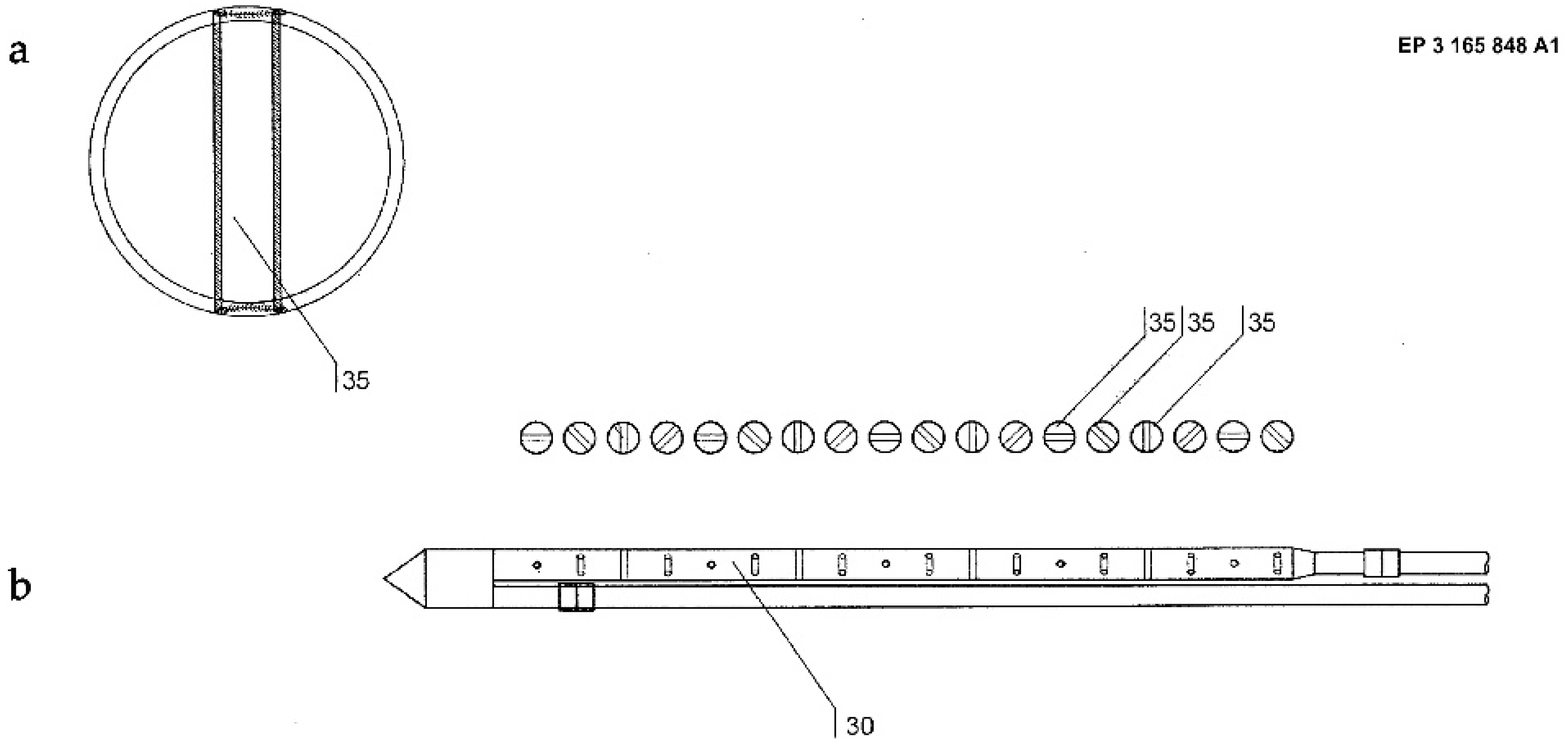
  • The use of steel exchangers when competing with PE.
  • A ring system that receives or gives off energy over a length of about 5 m.
  • One direction of flow and regeneration of the system.
  • The possibility of expanding the system with additional rings.

4. Conclusions

In the perspective of the next few years, the solutions described in this article are the only technically and economically proven technologies that can significantly reduce CO2 emissions in Poland, Europe, or the world. The solutions presented in this paper will also help to create a modern and environmentally friendly technical infrastructure, reducing operating costs by more than 50%.
Modern buildings are designed to fit in well with their surroundings. Numerous investments are changing the face of Polish cities, which acquire a European-level quality, and are becoming more and more attractive to live, work, and spend time in. Innovative architecture, environmentally friendly technologies, such as an FCH with an ice-water ring network, as described in this article, extended road and motorway infrastructure, commerce, restaurants, and culture create friendly public spaces with access to local services, jobs, and green areas.
According to the conducted research, after the introduction of the FCH HVAC Honeycomb Ring installation, there is a significant reduction in the energy demand, both in relation to traditional methods used in these facilities and to the basic HVAC technology itself. This leads to the creation of not only environmentally friendly facilities but also entire housing estates, which significantly increases the comfort of life.

Author Contributions

Conceptualization, J.W., W.S. and P.G.; methodology, W.S. and P.G.; software, W.S.; validation, J.W., W.S., P.G. and K.J.-G.; formal analysis, P.G. and K.J.-G.; investigation, P.G. and K.J.-G.; resources, W.S. and J.W.; data curation, W.S.; writing—original draft preparation, W.S., P.G. and K.J.-G.; writing—review and editing, P.G., K.J.-G. and W.S.; visualization, W.S., P.G. and K.J.-G.; supervision, J.W.; project administration, J.W.; funding acquisition, J.W. All authors have read and agreed to the published version of the manuscript.

Funding

This research received no external funding.

Data Availability Statement

Data are contained within the article.

Conflicts of Interest

The authors declare no conflict of interest.

References

  1. Kandelousi, M.S. HVAC System; BoD—Books on Demand: Norderstedt, Germany, 2018; ISBN 978-1-78984-432-0. [Google Scholar]
  2. Quan, S.J.; Chang, S.; Castro-Lacouture, D.; Igou, T.K.; Dutt, F.; Ding, J.; Chen, Y.; Pei-Ju Yang, P. Planning Decentralized Urban Renewable Energy Systems Using Algal Cultivation for Closed-Loop and Resilient Communities. Environ. Plan. B Urban Anal. City Sci. 2022, 49, 1464–1488. [Google Scholar] [CrossRef]
  3. Santillan, M.R.; Syn, J.W.; Charani Shandiz, S.; Huang, Y.; Pires de Lacerda, M.; Rismanchi, B. A Technology Assessment Approach for Achieving Sustainable Communities: An Energy Master Plan for a New Urban Development. Appl. Sci. 2022, 12, 3860. [Google Scholar] [CrossRef]
  4. Singh, T.; Solanki, A.; Sharma, S.K.; Nayyar, A.; Paul, A. A Decade Review on Smart Cities: Paradigms, Challenges and Opportunities. IEEE Access 2022, 10, 68319–68364. [Google Scholar] [CrossRef]
  5. Desvallées, L. Low-Carbon Retrofits in Social Housing: Energy Efficiency, Multidimensional Energy Poverty, and Domestic Comfort Strategies in Southern Europe. Energy Res. Soc. Sci. 2022, 85, 102413. [Google Scholar] [CrossRef]
  6. Danish; Ulucak, R. How Do Environmental Technologies Affect Green Growth? Evidence from BRICS Economies. Sci. Total Environ. 2020, 712, 136504. [Google Scholar] [CrossRef]
  7. Zaremba, D.; Kulesza, M.; Herman, A.M.; Marczak, M.; Kossowski, B.; Budziszewska, M.; Michałowski, J.M.; Klöckner, C.A.; Marchewka, A.; Wierzba, M. A Wise Person Plants a Tree a Day before the End of the World: Coping with the Emotional Experience of Climate Change in Poland. Curr. Psychol. 2022, 42, 27167–27185. [Google Scholar] [CrossRef]
  8. Adua, L. Super Polluters and Carbon Emissions: Spotlighting How Higher-Income and Wealthier Households Disproportionately Despoil Our Atmospheric Commons. Energy Policy 2022, 162, 112768. [Google Scholar] [CrossRef]
  9. Chen, Y.; Lee, C.-C. Does Technological Innovation Reduce CO2 Emissions?Cross-Country Evidence. J. Clean. Prod. 2020, 263, 121550. [Google Scholar] [CrossRef]
  10. Coma, J.; Maldonado, J.M.; de Gracia, A.; Gimbernat, T.; Botargues, T.; Cabeza, L.F. Comparative Analysis of Energy Demand and CO2 Emissions on Different Typologies of Residential Buildings in Europe. Energies 2019, 12, 2436. [Google Scholar] [CrossRef]
  11. Zou, Y.; Zhao, J.; Ding, D.; Miao, F.; Sobhani, B. Solving Dynamic Economic and Emission Dispatch in Power System Integrated Electric Vehicle and Wind Turbine Using Multi-Objective Virus Colony Search Algorithm. Sustain. Cities Soc. 2021, 67, 102722. [Google Scholar] [CrossRef]
  12. Tolegen, Z.Z.; Issabayev, G.A.; Yussupova, A.K.; Murzalina, G.B.; Amandykova, D.A. Architectural and Compositional Concepts of Environmentally Safe Urban Arrangement. Civ. Eng. Arch. 2022, 10, 1036–1046. [Google Scholar] [CrossRef]
  13. Burlig, F.; Preonas, L.; Woerman, M. Energy, Groundwater, and Crop Choice; National Bureau of Economic Research: Cambridge, MA, USA, 2021. [Google Scholar]
  14. Buffa, S.; Cozzini, M.; D’Antoni, M.; Baratieri, M.; Fedrizzi, R. 5th Generation District Heating and Cooling Systems: A Review of Existing Cases in Europe. Renew. Sustain. Energy Rev. 2019, 104, 504–522. [Google Scholar] [CrossRef]
  15. Qin, H.; Yu, Z.; Li, T.; Liu, X.; Li, L. Energy-Efficient Heating Control for Nearly Zero Energy Residential Buildings with Deep Reinforcement Learning. Energy 2023, 264, 126209. [Google Scholar] [CrossRef]
  16. Schwenkenbecher, A.; Brueckner, M. Renewable Energy. In The Routledge Companion to Environmental Ethics; Routledge: Abingdon, UK, 2022; ISBN 978-1-315-76809-0. [Google Scholar]
  17. Boretti, A. The Perspective of Enhanced Geothermal Energy Integration with Concentrated Solar Power and Thermal Energy Storage. Energy Storage 2022, 4, e303. [Google Scholar] [CrossRef]
  18. Mitali, J.; Dhinakaran, S.; Mohamad, A.A. Energy Storage Systems: A Review. Energy Storage Sav. 2022, 1, 166–216. [Google Scholar] [CrossRef]
  19. Wang, C.; Cheng, L.; Hao, Y.; Jiang, M.; Chen, K.; Shao, K. Efficiency Improvement and Application of the Groundwater Heat Pump Cooling System in Linglong Gold Mine. Geofluids 2022, 2022, e3191735. [Google Scholar] [CrossRef]
  20. Mandaroux, R.; Dong, C.; Li, G. A European Emissions Trading System Powered by Distributed Ledger Technology: An Evaluation Framework. Sustainability 2021, 13, 2106. [Google Scholar] [CrossRef]
  21. Vakiloroaya, V.; Samali, B.; Fakhar, A.; Pishghadam, K. A Review of Different Strategies for HVAC Energy Saving. Energy Convers. Manag. 2014, 77, 738–754. [Google Scholar] [CrossRef]
  22. Ma, Z.; Wang, S.; Xu, X.; Xiao, F. A Supervisory Control Strategy for Building Cooling Water Systems for Practical and Real Time Applications. Energy Convers. Manag. 2008, 49, 2324–2336. [Google Scholar] [CrossRef]
  23. Buffa, S.; Fouladfar, M.H.; Franchini, G.; Lozano Gabarre, I.; Andrés Chicote, M. Advanced Control and Fault Detection Strategies for District Heating and Cooling Systems—A Review. Appl. Sci. 2021, 11, 455. [Google Scholar] [CrossRef]
  24. Wrana, J.; Struzik, W.; Gleń, P. Natural Energy Stored in Groundwater Deposits as a New Way of Obtaining Green Energy for Urban Planners, Architects and Environmentalists. Energies 2022, 15, 4716. [Google Scholar] [CrossRef]
  25. Schibuola, L.; Tambani, C. Environmental Impact and Energy Performance of Groundwater Heat Pumps in Urban Retrofit. Energy Build. 2022, 261, 111964. [Google Scholar] [CrossRef]
  26. Wrana, J.; Struzik, W.; Kwiatkowski, B.; Gleń, P. Release of Energy from Groundwater/with Reduction in CO2 Emissions of More Than 50% from HVAC in the Extension and Revitalization of the Former Palace of the Sobieski Family in Lublin. Energies 2022, 15, 6627. [Google Scholar] [CrossRef]
  27. Puķīte, I.; Geipele, I. Different Approaches to Building Management and Maintenance Meaning Explanation. Procedia Eng. 2017, 172, 905–912. [Google Scholar] [CrossRef]
  28. Eini, R.; Linkous, L.; Zohrabi, N.; Abdelwahed, S. Smart Building Management System: Performance Specifications and Design Requirements. J. Build. Eng. 2021, 39, 102222. [Google Scholar] [CrossRef]
  29. Zhang, X.; Fong, K.F.; Yuen, S.Y. A Novel Artificial Bee Colony Algorithm for HVAC Optimization Problems. HVAC&R Res. 2013, 19, 715–731. [Google Scholar] [CrossRef]
  30. Shook, P.; Choi, J.-K.; Kissock, K. Analyzing the Multiscale Impacts of Implementing Energy-Efficient HVAC Improvements Through Energy Audits and Economic Input–Output Analysis. J. Energy Resour. Technol. 2022, 145, 041701. [Google Scholar] [CrossRef]
  31. Struzik, W. Arrangement of Devices for Obtaining Hot and Cold Water from a System Installed in Subterranean Water, for the Ring System Air Conditioning and Ventilation Equipment. 2020. Available online: https://ewyszukiwarka.pue.uprp.gov.pl/search/pwp-details/P.425437?lng=pl (accessed on 1 December 2023).
  32. Sommer, T.; Sulzer, M.; Wetter, M.; Sotnikov, A.; Mennel, S.; Stettler, C. The Reservoir Network: A New Network Topology for District Heating and Cooling. Energy 2020, 199, 117418. [Google Scholar] [CrossRef]
  33. Zhang, Y.; Wei, Z.; Zhang, M. Free Cooling Technologies for Data Centers: Energy Saving Mechanism and Applications. Energy Procedia 2017, 143, 410–415. [Google Scholar] [CrossRef]
  34. Poland. National Communication (NC); NC 8. Biennial Reports (BR). BR 5; UNFCCC: Bonn, Germany, 2022. [Google Scholar]
Figure 1. Temperature distribution for saturated soil in winter, summer. Red line—groundwater temperature at 10 m. Source: the authors.
Energies 16 07965 g001
Figure 2. Temperature distribution at lower depths recommended for FCH HVAC R installations. The graph shows temperatures at a depth of up to 7 m where, with the appropriate groundwater level, honeycomb rings can be made using the described technology. Source: the authors.
Energies 16 07965 g002
Figure 3. Indoor temperature distribution throughout the year in winter, summer—outdoor temperature (line blue), indoor temperature of individual rooms in the facility under study (line: green, red, and yellow). Source: the authors.
Energies 16 07965 g003
Figure 4. Energy recovery from an FCH system, view from BMS FCH unit. Source: the authors.
Energies 16 07965 g004
Figure 5. Results of energy recovery from an FCH system from ground water. Blue line—outside temperature; green line—temperature after the heater. Source: the authors.
Energies 16 07965 g005
Figure 6. Example of supplying buildings from FCH network from honeycomb ring. Source: the authors.
Energies 16 07965 g006
Figure 7. Example of: (a) cross-section and (b) scheme perforated FCH network head from honeycomb ring. Source: The authors.
Energies 16 07965 g007
Figure 8. Example of FCH R honeycomb ring network with a capacity of 720 kW/720 kW. Source: the authors.
Energies 16 07965 g008
Figure 9. Example of FCH R honeycomb ring network with a capacity of 720 kW/720 kW—one particular ring. Source: the authors.
Energies 16 07965 g009
Disclaimer/Publisher’s Note: The statements, opinions and data contained in all publications are solely those of the individual author(s) and contributor(s) and not of MDPI and/or the editor(s). MDPI and/or the editor(s) disclaim responsibility for any injury to people or property resulting from any ideas, methods, instructions or products referred to in the content.

