Review

A Review of the Sustainable Development of Solar Photovoltaic Tracking System Technology

School of Mechanical Engineering and Automation, Wuhan Textile University, Wuhan 430200, China
*
Authors to whom correspondence should be addressed.
Energies 2023, 16(23), 7768; https://doi.org/10.3390/en16237768
Submission received: 19 October 2023 / Revised: 17 November 2023 / Accepted: 23 November 2023 / Published: 25 November 2023
(This article belongs to the Section A2: Solar Energy and Photovoltaic Systems)

Abstract

:
In the face of the traditional fossil fuel energy crisis, solar energy stands out as a green, clean, and renewable energy source. Solar photovoltaic tracking technology is an effective solution to this problem. This article delves into the sustainable development of solar photovoltaic tracking technology, analyzing its current state, limiting factors, and future trends. The adjustment of solar panel orientation using solar tracking technology to maximize energy generation efficiency has been widely implemented in various fields, including solar power plants. Currently, limiting factors for this technology include energy generation efficiency, costs, and the complexity of various environmental conditions. In terms of sustainable development, this article emphasizes the importance of photovoltaic materials and manufacturing innovation, energy efficiency improvements, as well as the integration of smart and digital technologies. Future trends include higher precision, broader applications, and lower costs. Solar photovoltaic tracking technology will play a pivotal role in global energy production, fostering the realization of a clean and sustainable energy future.

1. Introduction

With the advancement and progression of industrialization, the demand for energy has steadily climbed. Traditional fossil fuels are gradually depleting, and their usage has adverse effects on the global climate [1,2,3]. Research indicates that by 2100, the global average temperature will rise by over 5 °C compared to pre-industrial levels [4]. With the ongoing development and progress of industrialization, the demand for energy continues to surge, leading to the exploration and utilization of renewable green energy sources. Solar energy, derived from the Sun’s radiation [5], can be converted into electricity or thermal energy using solar panels. It finds applications in electricity generation, heating, and various other energy needs. Solar energy is a clean and environmentally friendly source with vast potential. It can reduce dependency on fossil fuels, decrease greenhouse gas emissions, and contribute to achieving sustainable energy goals. The conversion of solar energy into electricity is accomplished through photovoltaic (PV) cells, with the output power of these cells depending on the amount of solar energy they collect [6]. The principle behind this process is that when sunlight strikes the solar panel, photons excite electrons within the semiconductor, causing them to move and generate an electric current.
In order to improve energy conversion efficiency, advancements have been made in solar energy systems since Finster’s [7] mechanical solar system design in 1962. In 1975, McFee [8] proposed a novel solar tracking system (STS) that utilized a central receiver to collect sunlight concentrated by an array of surrounding reflective mirror units, determining the Sun’s position based on statistical data from the reflection of each unit. This approach aimed to enhance the energy collection rate per unit of time. Simultaneously, Dorian et al. [9] designed an electrically controlled solar tracking device in 1980. This device could detect deviations in the Sun’s position, ensuring that the collector was directed toward the Sun. Additionally, when the collector temperature exceeded a certain limit, a thermal switch would disconnect it from the Sun, prolonging its lifespan. This technology played a pivotal role in initiating the commercial application of STSs in the 1980s. Significant progress has been made from simple mechanical structures to electrical control, from passive control to active control [9]. The transition from passive control technology to active control technology has brought about a qualitative transformation in solar tracking (ST). Both passive and active ST technologies have increased the amount of solar energy collected to varying degrees. To further analyze the impact of passive and active control on ST technology, scholars have conducted in-depth research. Passive tracking systems rely on the physical properties of materials such as shape memory alloys or chlorofluorocarbons [10,11]. When photovoltaic panels are not oriented vertically toward the Sun, uneven heating on their sides causes expansion on one side and contraction on the other, aligning the panels as closely as possible with the Sun to achieve tracking objectives. Active tracking systems, on the other hand, employ microcontrollers, sensors, actuators, etc., to continuously track the Sun [12,13]. Generally, when the microcontroller or sensor detects the movement of the Sun, it sends a signal to drive the motor, adjusting the photovoltaic panels to track the Sun. The purpose of tracking systems is to maximize the solar radiation received by the solar panels. Active tracking systems are further categorized into two types based on degrees of freedom: single-axis STS(s) and dual-axis STS(s). A single-axis tracking system typically provides one rotational degree of freedom in its motion mechanism [14]. It has a simpler structure and lower control complexity [15]. Considering the ground as a reference, the Sun’s movement relative to the ground can be divided into north–south and east–west motions, which mainly influence changes in elevation and azimuth angles [16]. Therefore, dual-axis tracking systems were introduced, featuring two mutually perpendicular rotational degrees of freedom [17]. Dual-axis tracking systems have more complex structures and control strategies.
STS(s) can be classified into closed-loop tracking systems and open-loop tracking systems based on their control mechanisms. Closed-loop tracking systems employ sensors to detect the real-time position of the Sun, feed this information back to a microprocessor, compare the error, and then drive the motor to correct the error. For example, Roth et al. [18] designed a dual-axis STS comprising a photoelectric detector, two direct current (DC) servo motors, and a pyranometer measuring solar radiation. The photoelectric detector detects the Sun’s position and guides the motors to track the Sun. When the solar radiation intensity falls below 140 W/m2, the pyranometer records nearly zero solar radiation. In contrast, when the solar radiation intensity exceeds 140 W/m2, the system operates normally. Open-loop tracking systems, on the other hand, utilize astronomical algorithms preloaded in the controller to track the Sun’s position. Abdallah et al. [19] designed an open-loop, Programmable Logic Controller-controlled dual-axis solar tracker. By comparing it with energy collected from a surface fixed at a 32° tilt to the south, the results showed a 41.34% increase in energy collection on the tracking surface. Typically, open-loop tracking systems employ tracking strategies based on solar trajectory calculations, whereas closed-loop tracking systems use sensor-based tracking strategies or a combination of solar trajectory calculations and sensor-based tracking strategies.
Solar power generation faces economic challenges such as low net electricity output per unit of land area [20], high construction costs, long payback periods [21], material sustainability, and efficiency issues [22,23]. Song et al. [24] designed a daylighting system model based on a dual-axis system composed of optical fibers and a solar tracking model. The tracking accuracy is superior to 0.1°, ensuring that the overlap between the surface focal spot and the incident surface is greater than 80%. This system comprises two feedback loops, utilizing angle encoders and a specific array of photodiodes for coarse and fine adjustments, ensuring excellent tracking performance. The theoretical optical transmission efficiency reaches 42%. Optimizing the tracking system and enhancing its precision can effectively increase electricity generation efficiency [25]. Gabe et al. [26] developed a dual-axis autonomous STS characterized by its low cost and low power consumption. This system includes the design, construction, and assembly of the entire mechanical structure, electrical systems, and devices, as well as the control logic responsible for all module movements to locate the position of maximum solar radiation. Even under cloudy conditions, this tracking system performs well. Compared to fixed systems, this tracking system can reduce the investment payback period of individual photovoltaic panels by 8%. Consideration has been given not only to cost-effectiveness and shortened investment payback but also to the impact of weather changes on the tracking system. Advances in such technologies enhance the economic viability of solar tracking systems [27,28] and improve their environmental adaptability [25,29,30]. With material advancements, thin-film technology has effectively replaced silicon in solar panels. Materials such as cadmium sulfide, cadmium telluride, and copper indium selenide sulfide [23] in thin-film technology, along with the use of polymers in solar panel construction, offer advantages such as low cost, lightweight, and environmental friendliness [31].
In reviewing the technological development of solar power tracking systems, this paper is divided into six sections. The aim is to comprehensively explore the sustainable development of solar tracking technology through a detailed analysis of research on solar tracking systems. The focus lies on analyzing the current state, limiting factors, and future trends of this technology. This study involves comparative analyses of PV materials’ performance in STS(s), improvements in energy efficiency through control methods, and the application of multi-environment adaptive strategies. This paper discusses the pivotal role of STS(s) in global energy production, emphasizing their contribution to achieving a clean and sustainable energy future.

2. Photovoltaic Cell

A PV system refers to a system that utilizes the PV effect of semiconductor materials to convert solar energy into electrical energy. PV cells are an indispensable component of this system. The key parameter for assessing the performance of PV cells is conversion efficiency, which refers to the ability of a PV cell to convert solar energy into electrical energy [32]. Conversion efficiency is closely related to the material characteristics of PV panels and can be categorized into four generations, as shown in Table 1 [33], which compares different materials used in PV cells. The first-generation PV cell materials include monocrystalline silicon (m-Si), polycrystalline silicon (p-Si), and amorphous silicon (a-Si). The second-generation PV cells focus on thin-film technology, where cell materials are manufactured in the form of thin films. Materials in this category include cadmium telluride (CdTe), cadmium sulfide, copper indium selenide, and copper indium gallium selenide (CIGS). The third-generation photovoltaic cells incorporate organic materials and nanotechnology, building upon the previous generation. This category includes photochemical solar cells, dye-sensitized solar cells (DSSCs), polymer solar cells, and nanocrystal solar cells. The fourth-generation cells are characterized by flexibility and low cost. These cells consist of stable and advanced inorganic nanostructures (such as metal nanoparticles and metal oxides) combined with organic nano-materials like carbon nanotubes, graphene, and their derivatives [23,33,34,35,36,37].
Since 1948, when Ohl utilized silicon as the material for PV cells, it marked the initiation of the era of PV power generation [38]. Until today, silicon remains the primary material for PV cells [39,40]. Silicon, as the predominant material in PV cells, boasts advantages such as abundant resources, mature technology, high conversion efficiency, and reliability. However, its bandgap structure limits the absorption range of the solar spectrum, and its weight, resistance to lightweighting, high energy consumption in the manufacturing process, and relatively elevated production costs are considered drawbacks. Despite these challenges, silicon PV cells remain the current mainstream and reliable technology. Ongoing research and technological advancements hold the promise of further enhancing their performance and reducing costs [41]. Gallium arsenide (GaAs), as a material for PV cells, presents advantages such as high efficiency, temperature stability, and radiation tolerance, particularly excelling in broad-spectrum responsiveness and high-temperature environments. Nevertheless, challenges persist in its widespread commercial application due to high costs and the relative scarcity of gallium. The application of thin-film technology in GaAs photovoltaic cells offers potential for flexible manufacturing, yet addressing cost and material supply issues is imperative for the extensive deployment of GaAs in the photovoltaic sector [42,43]. The application of a-Si in PV cells exhibits diverse characteristics. Manufactured through thin-film technology, it imparts flexibility to the cells, making them suitable for flexible designs, and is associated with relatively lower manufacturing costs. The a-Si PV cells demonstrate efficient absorption of solar radiation, particularly excelling in low-light conditions, rendering them well-suited for variable light environments. Their relatively lightweight nature and adaptability to non-ideal lighting and environmental conditions make them feasible for specific application scenarios. However, challenges persist in the form of relatively lower conversion efficiency and shorter lifespan, necessitating comprehensive consideration across various application contexts [44]. Cadmium telluride (CdTe) serves as a prominent material for PV panels, showcasing several advantageous characteristics. Demonstrating high-efficiency conversion, thin-film manufacturing techniques, relatively low production costs, and adaptability to high-light environments, CdTe PV cells excel in the realm of photoelectric conversion. Their inherent lightweight and flexibility, conducive to flexible design, afford increased versatility for diverse application scenarios. Simultaneously, the production process of CdTe is relatively environmentally friendly, mitigating adverse environmental impacts. However, it is crucial to note the use of the toxic element cadmium in its manufacturing, necessitating cautious management and recycling practices [45]. CIGS is a material employed in thin-film photovoltaic cells, exhibiting notable performance in photoelectric conversion. Its high-efficiency conversion attributes stem from a composition of multiple elements, including copper, indium, gallium, and selenium. Fabricated through thin-film technology, CIGS cells possess heightened flexibility and lightweight characteristics, rendering them suitable for various application scenarios. Their superior performance in high-intensity light conditions is attributed to optimized absorption properties. Additionally, CIGS cells demonstrate a relatively lower demand for raw materials, holding promise for reducing dependence on scarce resources. However, the high manufacturing costs and the scarcity of certain elements may pose constraints on its feasibility for large-scale commercial applications. Despite these challenges, ongoing research and exploration in the field aim to overcome these limitations through technological innovation [46,47]. DSSCs, as a photovoltaic conversion technology, exploit the mechanism whereby dye molecules absorb photons, transferring the excited electrons to an oxide semiconductor to generate charge pairs. This absorption mechanism demonstrates high efficiency within the visible spectrum. The utilization of straightforward manufacturing processes and flexible materials in DSSCs holds the potential for cost reduction and adaptability to diverse applications. However, challenges persist in terms of stability and long-term performance for DSSCs [48]. Quantum dot solar cells represent an innovative solar energy conversion technology that leverages nanoscale semiconductor particles (quantum dots) for the absorption and conversion of solar radiation. The distinctive feature lies in their spectral tuning capability, achieved by adjusting the quantum dot size to efficiently absorb light of different wavelengths, thereby enhancing the photovoltaic conversion efficiency. Furthermore, the unique electronic structure of quantum dots allows for the generation of multiple electron–hole pairs from a single photon excitation, augmenting current output. This technology also harbors the potential for flexible design, accommodating curved and bendable surfaces. However, quantum dot solar cells face challenges in terms of complex fabrication processes, stability, and long-term performance. Ongoing academic efforts aim to address these challenges and advance the development of quantum dot solar cell technology [49,50,51,52]. Perovskite solar cells represent a thin-film solar cell technology based on the perovskite crystal structures, a mineral characterized by a tetragonal crystal lattice. Typically composed of both organic and inorganic materials, this structure imparts superior optoelectronic properties, facilitating the efficient capture and conversion of solar photons. Exploiting the exceptional optoelectronic characteristics of perovskite, these cells achieve effective capture and conversion of solar photons. Their high photovoltaic conversion efficiency positions them as robust contenders to replace traditional silicon solar cells. Despite the relative simplicity of their fabrication process and the potential for flexible design, challenges persist in terms of stability under conditions such as humidity, temperature variations, and changes in illumination, as well as considerations regarding sustainability and environmental friendliness [39]. Multijunction solar cells exhibit a high photovoltaic conversion efficiency, capturing a broad spectrum of sunlight wavelengths through multiple bandgap structures to enhance overall efficiency. The efficient response to both visible and infrared light makes them particularly suitable for high-performance photovoltaic applications, such as space exploration and satellite power systems. However, the complex fabrication process and relatively higher manufacturing costs impose limitations on their large-scale production [53]. Graphene and its derivatives have garnered significant attention in the field of photovoltaic cells. Graphene, known for its outstanding conductivity and transparency, serves as an efficient electrode material, with some derivatives maintaining these properties. Their tunable optical characteristics contribute to enhancing the photovoltaic cell’s photoelectric conversion efficiency. The flexibility in design and the ability to modulate electrochemical performance make these materials suitable for various photovoltaic applications. For instance, graphene oxide exhibits superior electrical properties compared to graphene [54,55,56]. Carbon nanotubes demonstrate outstanding potential applications in photovoltaic cells. Their exceptional electrical conductivity makes them an ideal electrode material, effectively facilitating electron transfer and enhancing the overall performance of photovoltaic cells. With infrared spectrum absorption capability, carbon nanotubes can expand the spectral responsiveness of photovoltaic cells, thereby improving photoelectric conversion efficiency. The flexible design of carbon nanotubes allows for the manufacturing of flexible photovoltaic cells adaptable to various surfaces and shapes, broadening their application scope. Additionally, carbon nanotubes can form transparent conductive films suitable for manufacturing transparent solar cells or other see-through photovoltaic materials. However, practical applications still face challenges, including production costs, large-scale manufacturing, and stability issues [57,58,59].
Table 1. Comparative analysis of photovoltaic cells with varied materials [33,39,40,41,60].
TechnologyEfficiencyManufacturing ProcessAdvantagesLimitations
Monocrystalline Silicon15–25%The m-Si wafers are manufactured using the Czochralski process, which involves growing silicon ingots from small single-crystal silicon seeds and subsequently cutting them to obtain m-Si wafers.Stable; efficient; long lifespan.High production costs; sensitivity to temperature; absorption issues; significant material loss.
Polycrystalline Silicon10–18%Polycrystalline silicon can be industrially produced using the Siemens process. This method encompasses the vaporization of metallurgical-grade silicon, distillation of the resulting product, and final deposition to achieve ultra-pure silicon.Simple production process; cost-effective; reduces silicon wastage; superior absorption compared to amorphous silicon.Lower efficiency; more temperature-sensitive.
Gallium Arsenide28–30%GaAs is made through a reaction of Ga and As in vapor, with a four-step process: growing a crystal ingot, processing a wafer, adding thin slices through epitaxy, and making devices by bonding, adding layers, isolating, and packaging.High stability; low-temperature sensitivity; excellent absorption; high efficiency.Extremely expensive.
Amorphous Silicon5–12%The production of a-Si thin-film solar cells uses a roll-to-roll technique. Metal sheets are cleaned, cut, and coated with insulation. a-Si is deposited onto a reflector, followed by a transparent conductive oxide on the silicon layer. Laser cutting connects layers, and the module is encapsulated.Inexpensive; abundant; non-toxic; high absorption coefficient.Low efficiency; difficult material doping; short minority carrier lifetimes.
Cadmium Telluride15–16%CdTe solar cell manufacturing involves depositing cadmium sulfide and CdTe layers. Laser cutting introduces an insulator, enabling the addition of the positive electrode. The cell is then encapsulated, wired, and placed on tempered glass.High absorption coefficient; requires fewer materials for manufacturing.Lower efficiency; cadmium is highly toxic; tellurium is limited and more temperature-sensitive.
Copper Indium Gallium Selenide20%CIGS solar cell manufacturing involves choosing a substrate, applying a molybdenum film as the back electrode, growing the p-type CIGS layer, depositing a transparent conductive oxide buffer layer, and adding an anti-reflective coating to improve cell efficiency.Requires fewer materials for manufacturing.Very expensive; unstable; highly temperature-sensitive; unreliable.
Dye-Sensitized Solar Cells5–20%The manufacturing process of DSSCs involves the deposition of a conductive layer, typically tin oxide, onto a glass substrate. Subsequently, an organic dye, capable of photon absorption, is applied on top of the conductive layer. Following this, an electrolyte, commonly in liquid form, is injected to provide a pathway for electron conduction. Finally, the cell is sealed through encapsulation to protect it from environmental influences.Low cost; low-light performance; wide-angle sensitivity; low internal temperature; robust and durable; long lifespan.Issues with temperature stability; presence of toxic and volatile compounds.
Quantum Dot Solar Cells11–17%The manufacturing process of quantum dot solar cells involves selecting a conductive solid substrate, synthesizing semiconductor materials in the form of quantum dots with specific optoelectronic properties, attaching the synthesized quantum dots to the substrate to form a sensitized layer, introducing a liquid electrolyte for electron conduction, using conductive materials like platinum as electrodes, and finally encapsulating the cell for stability and protection from external influences.Low production cost; low power consumption.Highly toxic properties; degradable.
Perovskite Solar Cells21%The manufacturing process of perovskite solar cells involves preparing a substrate (typically glass or flexible material), depositing electron and hole transport layers for efficient electron conduction, applying a perovskite layer, adding metal electrodes to collect electrons and holes, and finally encapsulating the components for enhanced stability and durability against environmental factors.Inexpensive and simple structure; lightweight; flexible; high efficiency; low production cost.Unstable
Multi-junction solar cells36%The manufacturing of multi-junction solar cells involves substrate preparation, deposition of semiconductor layers, incorporation of a transparent conductive layer, possible stacking for broader absorption spectrum, introduction of metal electrodes for charge collection, and final encapsulation for stability and environmental protection. This complex process aims to maximize the use of diverse sunlight wavelengths for efficient energy conversion.Highly efficientComplex; expensive.
The future prospects of PV technology are filled with both potential and challenges. While first-generation PV cells continue to dominate the market, second-, third-, and fourth-generation PV cells are gradually emerging, bringing new opportunities to the PV field. Second-generation PV cells, such as thin-film technology, have made significant progress, offering lower manufacturing costs and lighter weight, providing a competitive edge in specific applications. Third-generation PV cells involve novel materials and structures, enhancing efficiency and expanding the spectrum of light absorption. Particularly noteworthy are fourth-generation PV cells, including multi-junction cells based on nanomaterials and graphene PV cells, which have overcome some of the drawbacks of previous generations. Multi-junction cells demonstrate substantial potential in improving efficiency and reducing costs, especially with the utilization of low-cost manufacturing processes. The application of nanomaterials like graphene has further elevated the efficiency and performance of PV cells, positioning them as significant competitors in future PV technology. This development offers diverse choices for sustainable development.

3. Solar Radiation Angle Calculation and Theory

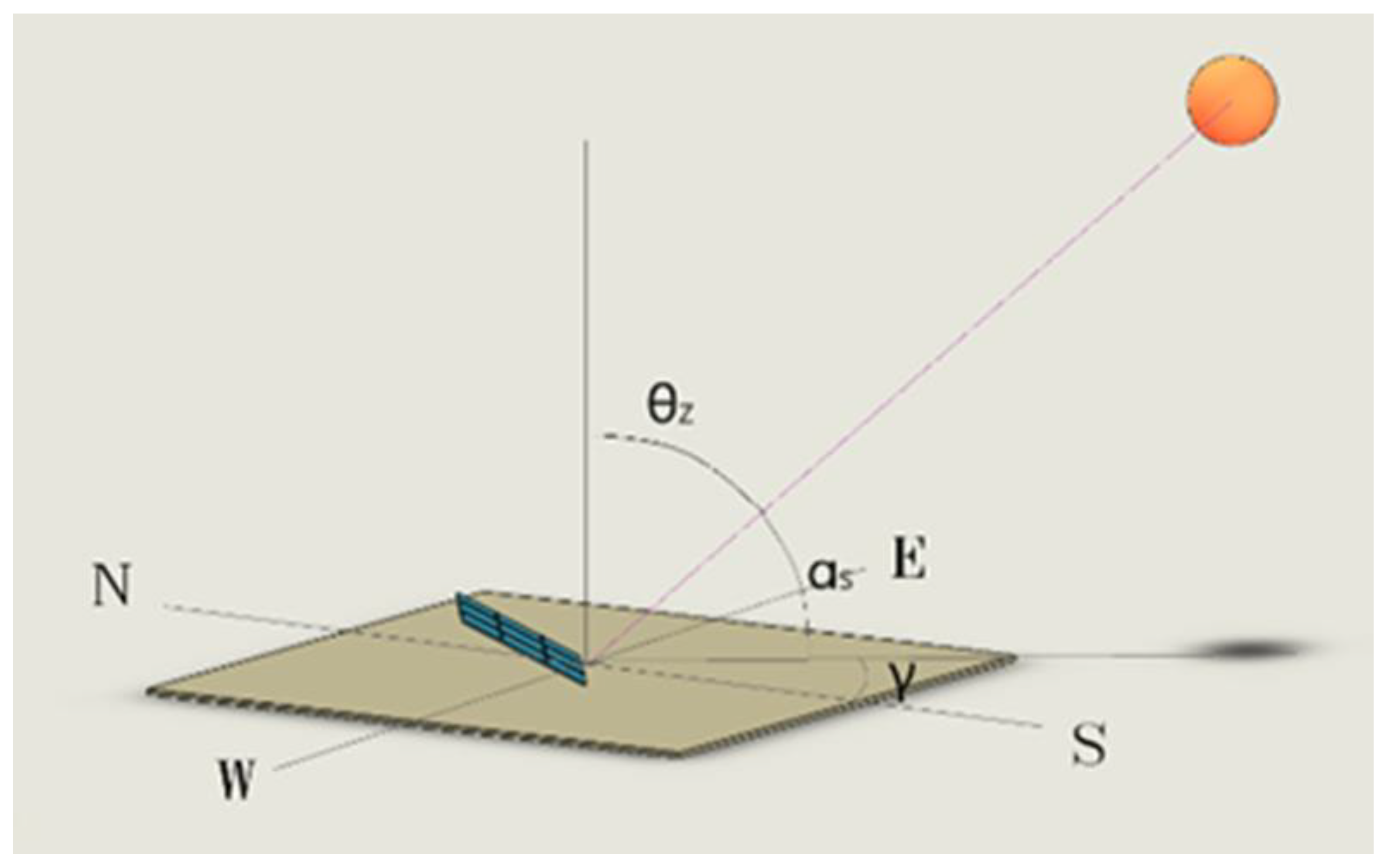
As shown in Figure 1, solar radiation has two main angles, namely, the azimuth angle and the elevation angle. With the changes in seasons, months, and dates, the amount of solar radiation received by photovoltaic panels needs to be calculated based on the angles of solar radiation to obtain the maximum value [61]. The specific parameters are shown in Table 2.
Elevation Angle ( α s ): The angle between the Sun’s rays and the horizontal plane, as per the definition α s = 90 ° θ z [63].
Azimuth Angle ( γ s ): The angle measured clockwise from the north along the horizon [65].
Surface azimuth angle ( γ ): The angle formed with the south along the horizon. Applicable to surfaces facing south, with positive values when facing southeast and negative values when facing southwest [65]. γ = 180 ° γ s .
Declination angle ( δ ): The angle between the plane of the Earth’s equator and the line connecting the Sun and the Earth’s center [62].
Incident angle ( θ ): The angle between the surface normal and the incoming sunlight [66].
Zenith angle ( θ z ): The angle between the direction of incoming sunlight and the zenith direction [63].
Latitude ( Φ ): The angle between the line connecting a point on the Earth’s surface to the Earth’s center and the plane of the equator. Positive values are taken in the Northern Hemisphere [63].
Hour angle ( ω ): At solar noon (12:00 p.m.), ω = 0 ° . Each hour corresponds to 15 ° , with negative values before solar noon and positive values after solar noon [63].
Tilt angle ( β ): The angle between the surface and the horizontal plane. Surfaces facing the equator are assigned positive values [66]. β = 90 ° α s = θ z .

4. Solar Tracking System Technological Advancements and Classifications

4.1. Classification Based on Drive Mechanisms

4.1.1. Passive Tracking Systems

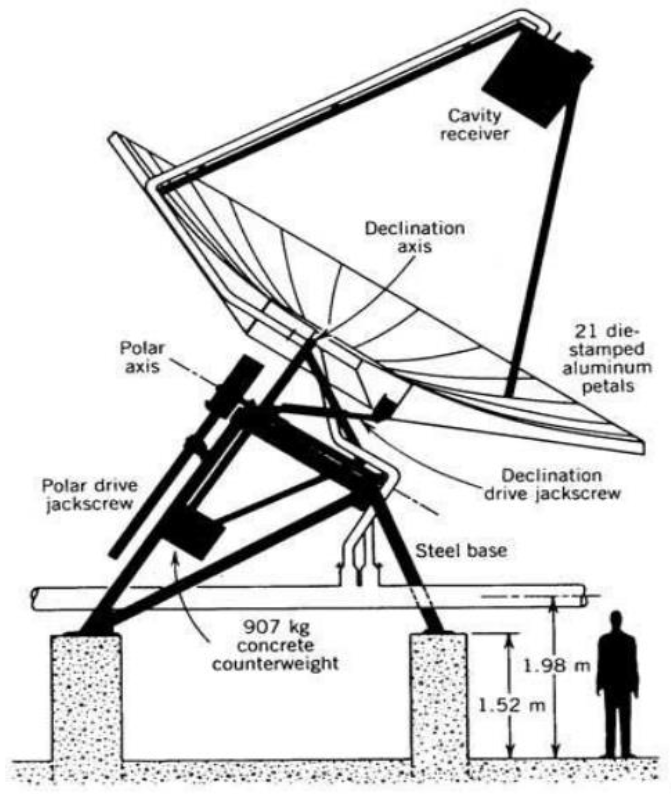
Passive solar tracking systems are relatively simple technologies that do not require an external power supply. Their purpose is to maximize the exposure of solar panels to sunlight, thereby enhancing the energy generation efficiency of solar energy systems [74]. Unlike active tracking systems, passive tracking systems do not rely on motors or control systems to adjust the orientation of solar panels. Instead, they utilize a series of physical principles and material characteristics. Passive tracking systems leverage the physical properties of materials, such as thermal expansion and contraction, typically using shape memory alloys or chlorofluorocarbons [10,11]. When the photovoltaic panels are not perpendicular to the Sun, uneven heating on both sides causes one side to expand and the other to contract, aligning the panels as vertically as possible with the Sun. The first commercial passive STS was introduced by Zomeworks in 1969, which effectively captured sunlight compared to fixed photovoltaic panels, thus increasing electricity output [75]. As shown in Figure 2, the system consisted of two identical cylindrical tubes placed on either side of the solar panel, equidistant from the central pivot, filled with fluid. Sunlight heated the fluid in one of the cylinders, causing it to evaporate and move to the other cylinder. The resulting imbalance in fluid mass was used to move the solar panel, achieving solar tracking [76]. Poulek [74] designed a single-axis shape memory alloy tracker, which deforms at temperatures below 70 °C and reverts to its original shape at temperatures above 70 °C, enabling effective tracking.
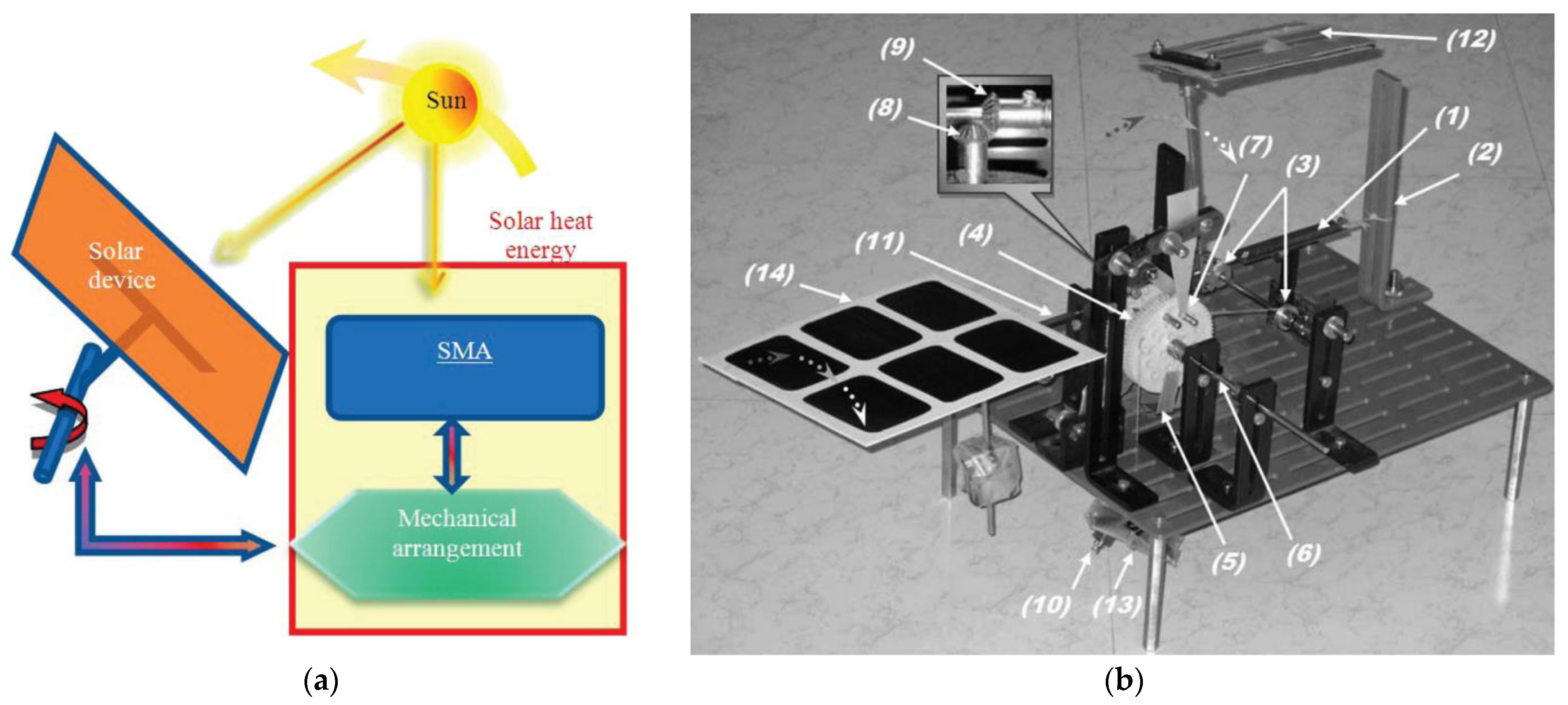
Ganesh et al. [77] devised a straightforward yet efficient solar tracking mechanism based on smart shape memory alloy (SMA) springs. The SMA spring components exhibit a dual function of sensing and actuation, as depicted in Figure 3; the mechanism is designed to track the Sun’s movement within an approximately 120-degree solar angle range throughout the day, from 8 a.m. to 4 p.m. This is achieved by mounting the SMA springs and lens device on the same axis to maintain a constant angular difference. This angular difference allows sufficient time for the SMA springs to heat up from solar exposure and cool down in still air. The operational sequence involves focusing sunlight onto the SMA springs through the lens, causing them to heat up and contract. This contraction pulls cables and a series of mechanical components, ultimately tilting the solar receiver toward the Sun. This tilt also moves the lens platform, ensuring sunlight no longer focuses on the SMA springs. When not subjected to heating, the SMA springs cool and elongate, while ratchet and pawl mechanisms prevent the solar receiver from rotating backward. Finally, the SMA actuator returns to the initial state, preparing for the next operational cycle. Pen et al. [78] explored the use of holographic gratings as passive solar trackers. The study found that in the central region of Russia, this technology could increase energy generation from PV panels installed on ‘smart’ windows by approximately 20%. To achieve a higher 35% signal increase, improvements in the diffraction characteristics of the grating are necessary. This can be achieved through the development of new materials or adopting relief forms with a mixed diffraction structure. Brito et al. [79] proposed a multi-axis passive solar tracking system that utilizes the length variations in vertical, thin, flat bars caused by thermal expansion in sunlight. These expansion differences in three different directions are magnified through a lever system to track the Sun’s apparent motion in the sky. Experimental results demonstrated that the system effectively enhances PV power output, increasing it by approximately 28%. Alemayehu et al. [80] addressed the challenge of returning photovoltaic panels to an eastern position before sunrise in passive solar trackers. They designed a bimetallic strip deflector that is independent of nighttime temperature fluctuations. Field tests showed that compared to fixed systems, this tracker exhibited a more stable power output, providing an additional 47 watts per m2, maximizing power output, and saving $71.75 per m2. The system’s energy collection efficiency increased by 24.86%, and accuracy improved by 96.4%, making it an economically efficient, easy-to-install and operate PV alternative. Additionally, it is not affected by nighttime temperature fluctuations, ensuring stability and reliability.
With continuous technological advancements and innovations, solar passive tracking systems, including the use of new materials, smart control systems, and efficient sensors, have significantly enhanced the energy production efficiency of solar energy systems. The costs associated with solar passive tracking systems are gradually decreasing, making this technology economically viable for wider applications and broader regions. In comparison to fixed systems, passive STS(s) reduce land occupancy and enhance energy utilization, thereby fostering ecological preservation and promoting the sustainability of energy resources. Solar passive tracking systems are inherently sustainable as they rely solely on solar energy without the need for external power sources. They contribute to a more sustainable energy future, alleviating pressure on finite energy resources.

4.1.2. Active Tracking System

An active tracking system employs devices such as microcontrollers, sensors, and actuators to continuously track the position of the Sun. The solar tracking system employs LDRs as photosensitive components to perceive the Sun’s position by monitoring changes in environmental light intensity. The microcontroller precisely reads the resistance values of LDRs with high accuracy and extensively compares them with the theoretical light intensity corresponding to the expected solar position, establishing a comprehensive model of disparities between the actual and anticipated positions. Utilizing the comparative outcomes, the microcontroller executes a sophisticated error calculation algorithm, generating an electric signal proportional to the deviation in solar position. This signal undergoes meticulous calibration to ensure compliance with the precision and responsiveness requirements of the system design. Subsequently, the microcontroller transmits the adjustment signal to the actuator, which, based on the signal characteristics (e.g., voltage, current), precisely controls the adjustment mechanism to achieve accurate alignment of the solar panel with the Sun. The actuator carries out the adjustment actions, ensuring the solar panel remains oriented towards the Sun throughout continuous monitoring. The system operates within a persistent iterative loop, continually sensing variations in solar position, computing errors, generating adjustment signals, and implementing correction actions. This iterative process guarantees the system’s prompt and accurate response to changes in the solar position, thereby maximizing the efficiency of solar energy collection [12]. Reference [81] indicates that solar hot water systems employing active tracking exhibit high tracking efficiency. Compared to fixed-angle solar hot water systems, active tracking technology increases the total stored thermal energy of solar hot water systems, leading to a 40% improvement in energy utilization efficiency. Stefenon et al. [82] focused on time series forecasting and proposed a solar energy prediction model based on the wavelet neural fuzzy algorithm, emphasizing the feature extraction role of wavelets in the model. The primary objective was to evaluate the potential of a hybrid generation prediction model incorporating ST technology to achieve reasonable accuracy, with a primary contribution related to improving the efficiency of PV panels. Through the construction of a hybrid computational model, the study explored the application potential of ST technology within specific time periods. In summary, compared to traditional nonlinear autoregressive models, this model demonstrates excellent performance, providing a promising approach to enhance the accuracy and efficiency of PV power generation.

4.2. Classification Based on Degrees of Freedom

4.2.1. Single-Axis Solar Tracking System

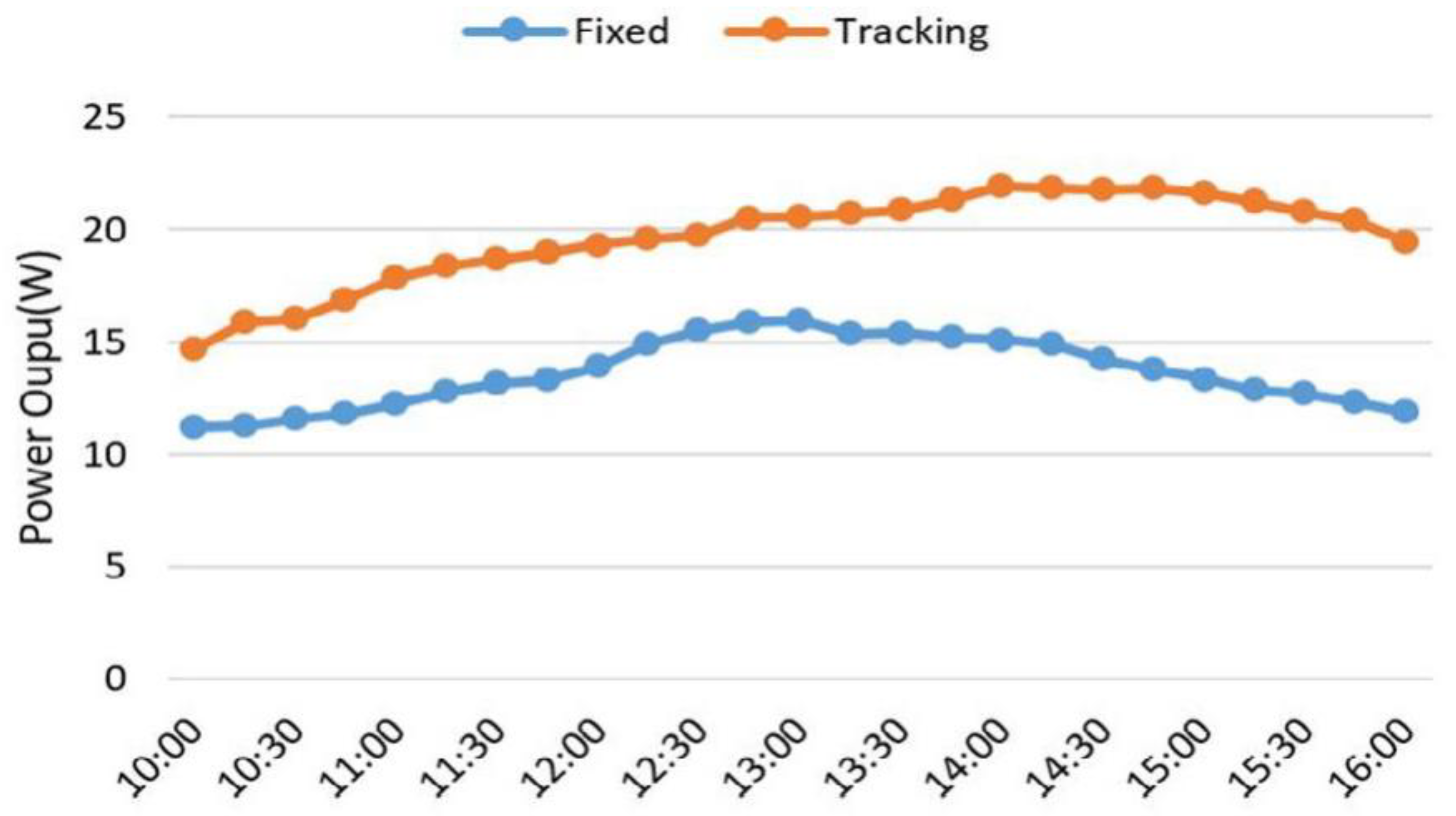
A single-axis tracking system typically refers to a mechanism providing one rotational degree of freedom [14], and it can be classified into three types: horizontal single-axis, vertical single-axis, and tilted single-axis. Horizontal single-axis STS(s) are suitable for equatorial and low-latitude regions, tilted single-axis systems are suitable for mid-latitude regions, and vertical single-axis tracking systems are suitable for high-latitude regions [83]. As shown in Figure 4, single-axis solar tracking significantly enhances energy conversion efficiency compared to fixed systems. An Arduino microcontroller receives data from a photosensitive resistor sensor to control a DC motor. Since the rotation of the solar panel requires low speed and high torque, while the DC motor operates at high speed and low torque, the system incorporates a small gear DC motor connected to a large gear to reduce speed and increase torque. Experimental results indicate that under similar clear-sky conditions, the solar panel of the single-axis tracking system generated 1742.88 watt-hours of electricity, whereas the panel of the fixed system produced only 829.6 watt-hours of electricity [84]. Gutiérrez et al. [85] compared the energy collection efficiency of two single-axis tracking strategies across 22 different global regions. These strategies involved Two-point tracking (morning and afternoon) and three-point tracking (morning, noon, and afternoon). The results indicate that, compared to fixed solar energy systems, dual-point tracking can provide an annual radiation gain ranging from 41% to 74%, while triple-point tracking can offer gains ranging from 68% to 87%.
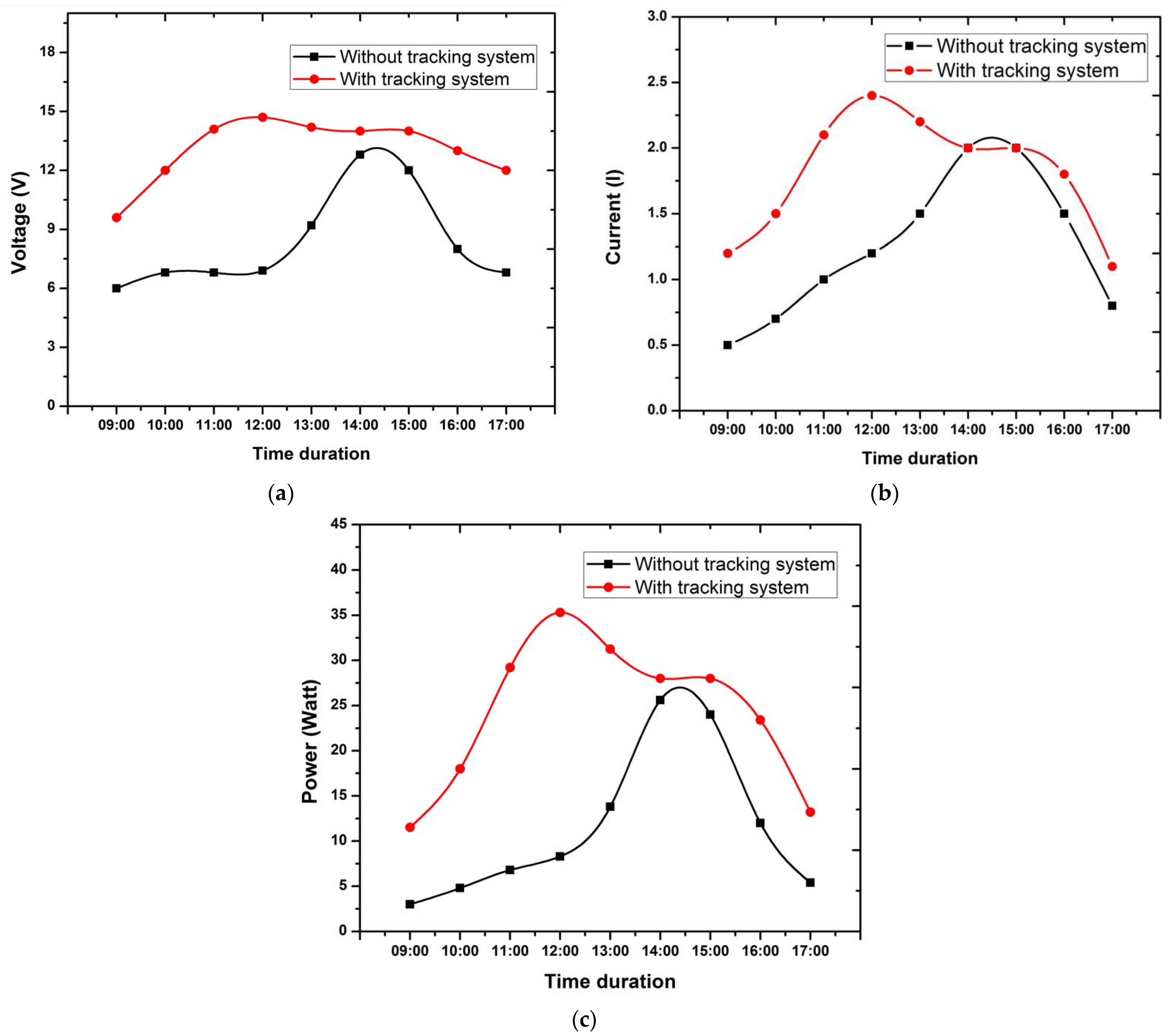
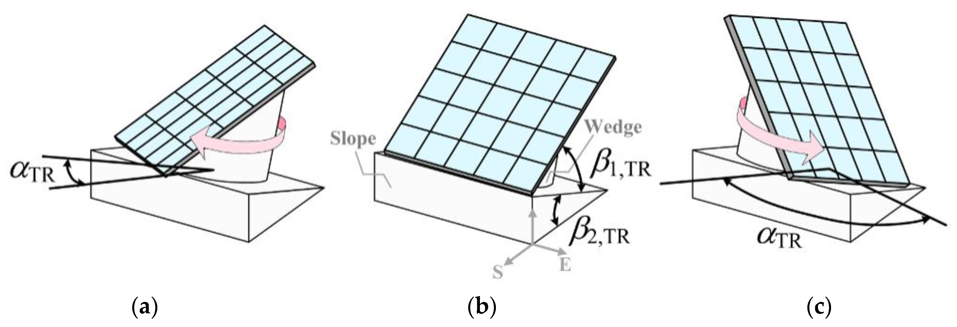
In the study by Rani et al. [86], the concept involved utilizing light-dependent resistors (LDRs) to ensure the solar panels consistently face the Sun. Two separate LDRs (LDR1 and LDR2) were positioned separately, and if the solar panel was not aligned with the Sun, one sensor would detect a shadow. A microcontroller served as the controller, directing the motor’s movement through a relay to align the solar panel vertically with the Sun. The objective of this system was to maximize the efficiency of solar panels, ensuring they consistently capture the maximum solar radiation. As shown in Figure 5, the aim of Munanga et al.’s [87] research was to create an intelligent single-axis solar tracking device. The output from the LDR sensors was used to determine solar radiation, calculate the required tilt angle for the solar panels, and then adjust the stepper motor’s speed. Through experimental validation, as illustrated in Figure 6, this system was able to increase efficiency by 25% on a fixed 24-watt solar panel. Zhu et al. [88] designed a novel structure of a single-axis solar tracking system based on mathematical expressions for tracking derived from the Sun–Earth geometry and a predictive solar radiation model, as shown in Figure 7. The theoretical model calculated the optimal angles β 1 , T R , β 2 , T R and rotation angle α T R . The system utilized an inclined slope with angle β 2 , T R , facing south and installed on the ground. On the surface of this slope, wedges with a tilt angle β 1 , T R were mounted, and photovoltaic panels were then placed on these wedges. The coordination of angles β 1 , T R , β 2 , T R , and α T R facilitated solar tracking. Compared to traditional dual-axis tracked panels, this innovative tracking structure achieved an annual solar radiation incidence ratio as high as 96.40%. Simulation results demonstrated significant performance advantages over existing single-axis tracking structures across nearly all latitudes.
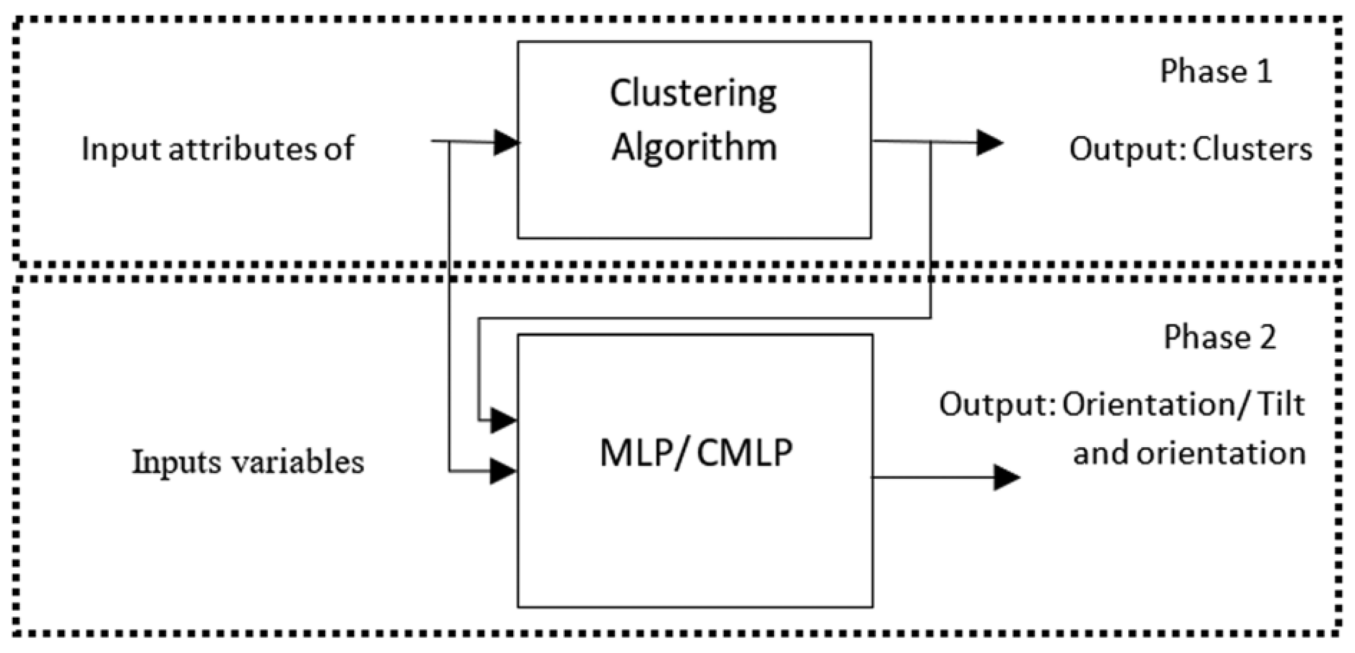
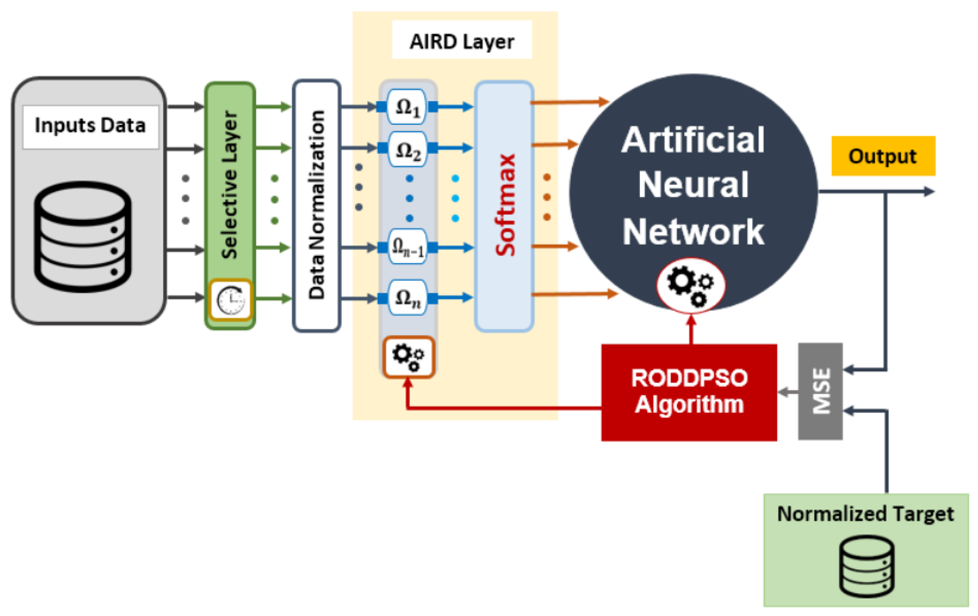
As shown in Figure 8 and Figure 9, AL-Rousan et al. [89,90] proposed an efficient and low-complexity single-axis and dual-axis STS. Typically, multi-layer perceptron is used as controllers for STS(s). However, when the input data are complex, the multi-layer perceptron struggles to accurately interpret the relationships between the data, leading to a decrease in performance. To overcome this issue, a novel approach was proposed in the research, where the relationships between data samples were pre-mapped and used together with the original input data as inputs for the neural network. This approach aimed to better guide the neural network to achieve the desired objectives, enhancing the speed and accuracy of the prediction output. Specifically, the study employed a logistic regression model for training, utilizing unsupervised clustering techniques such as k-means, fuzzy c-means, and hierarchical clustering algorithms. The logistic regression model predicted the tilt angles and orientation angles of solar panels using two distinct datasets. The research findings demonstrated that compared to traditional models, the proposed multi-layer perceptron or cascaded multi-layer perceptron–logistic regression system improved the prediction accuracy in both single-axis and dual-axis STS(s) while reducing the mean squared error rate. The study revealed that although daily variables had no correlation with orientation and tilt angles, they were highly effective in enhancing the performance of solar trackers. While linear regression models could only achieve an accuracy of less than 70% for the provided data, non-linear models could more accurately predict the optimal directions and tilt angles. The prediction accuracies of the single-axis tracker for the multi-layer perceptron and cascaded multi-layer perceptron models based on monthly, daily, and time variables reached 96.85% and 96.83%, respectively. Sharath et al. [91] proposed a hybrid power system combining artificial intelligence with single-axis solar tracking wind turbines. This investigation aimed to enhance the efficiency of hybrid solar and wind power generation systems by using a single-axis solar tracker to improve the performance of solar panels. Hybrid solar and wind power generation systems are considered sustainable electricity solutions that can consistently meet power demands. The advantage of hybrid systems lies in using artificial neural networks to predict and analyze solar and wind energy prediction models, helping compensate for the individual fluctuations of solar and wind energies, thus mitigating the impact of adverse weather conditions on energy supply. Bin Huang et al. [92] developed a horizontal single-axis PV array STS using spatial projection analysis implemented with MATLAB Simulink tools. They established a slope-based single-axis tracking strategy, considering major parameters, such as shadow area ratio and average solar irradiance, to determine the optimal tilt angle of the photovoltaic array and its corresponding ideal adjustments. Table 3 presents the parameters of recently researched single-axis STS(s).
The sustainable development of single-axis STS(s) holds immense potential. Future single-axis STS(s) will employ more intelligent control systems, potentially incorporating artificial intelligence and machine learning algorithms to monitor solar positions and light conditions in real time, enabling precise adjustments of PV panel angles. This advancement will enhance system response speed, ensuring that PV panels are consistently oriented toward optimal positions. In terms of materials, renewable and environmentally friendly materials will be used in the manufacturing of STS(s), reducing dependence on finite resources and minimizing environmental impact. Future single-axis tracking systems may integrate with other energy systems, such as wind energy or energy storage systems, reducing energy costs. Additionally, future single-axis STS(s) could integrate self-powering mechanisms. In summary, future single-axis STS(s) are poised to become a key technology in the field of sustainable energy, offering higher efficiency and reliability. These advancements will contribute to reducing reliance on traditional energy sources, paving the way for a cleaner and more sustainable energy future.

4.2.2. Dual-Axis Solar Tracking System

The Earth can be considered as a reference, and the movement of the Sun relative to the Earth can be divided into annual and daily motions; these are the primary factors influencing changes in tilt angle and azimuth angle. Therefore, a higher tracking accuracy dual-axis tracking system is introduced. A dual-axis tracking system has two mutually perpendicular rotational degrees of freedom [16]. The dual-axis STS is an advanced system used for solar power generation, designed to maximize the energy collection efficiency of solar panels by continuously tracking the Sun’s position. This system typically employs sensors and motors to monitor the Sun’s position and automatically adjust the orientation of the solar panels.
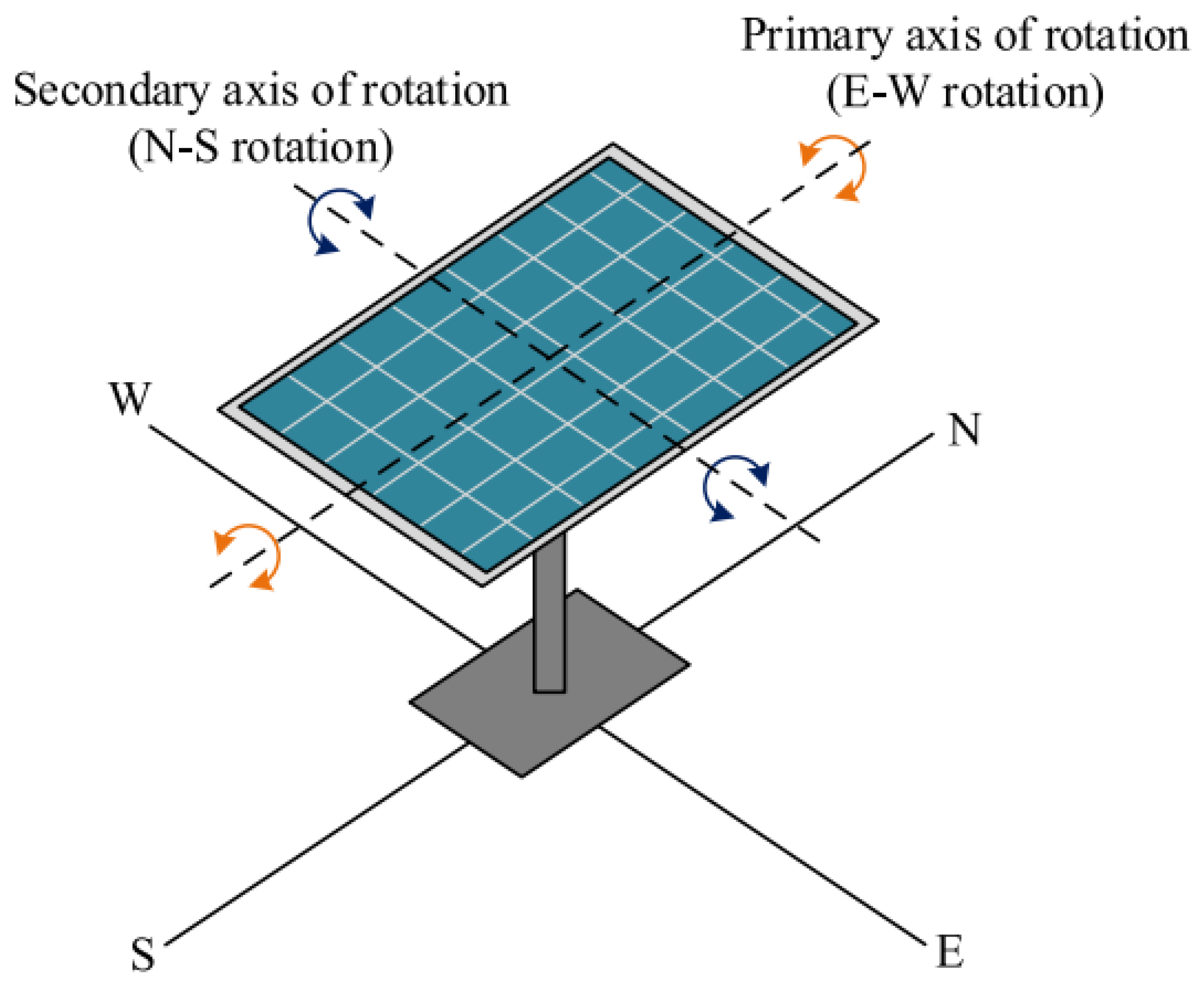
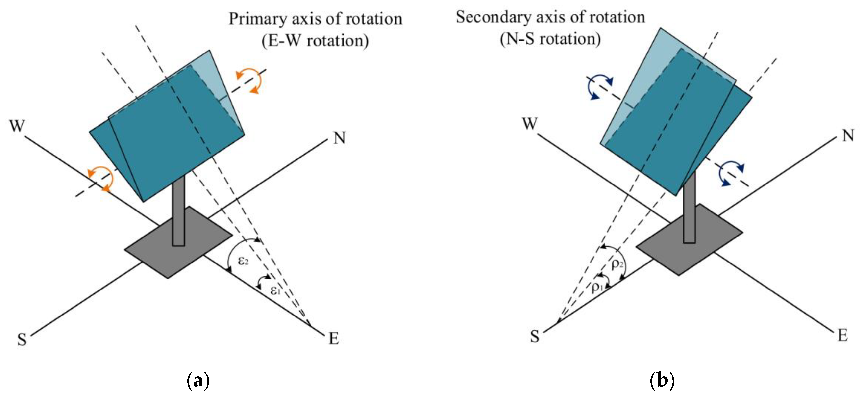
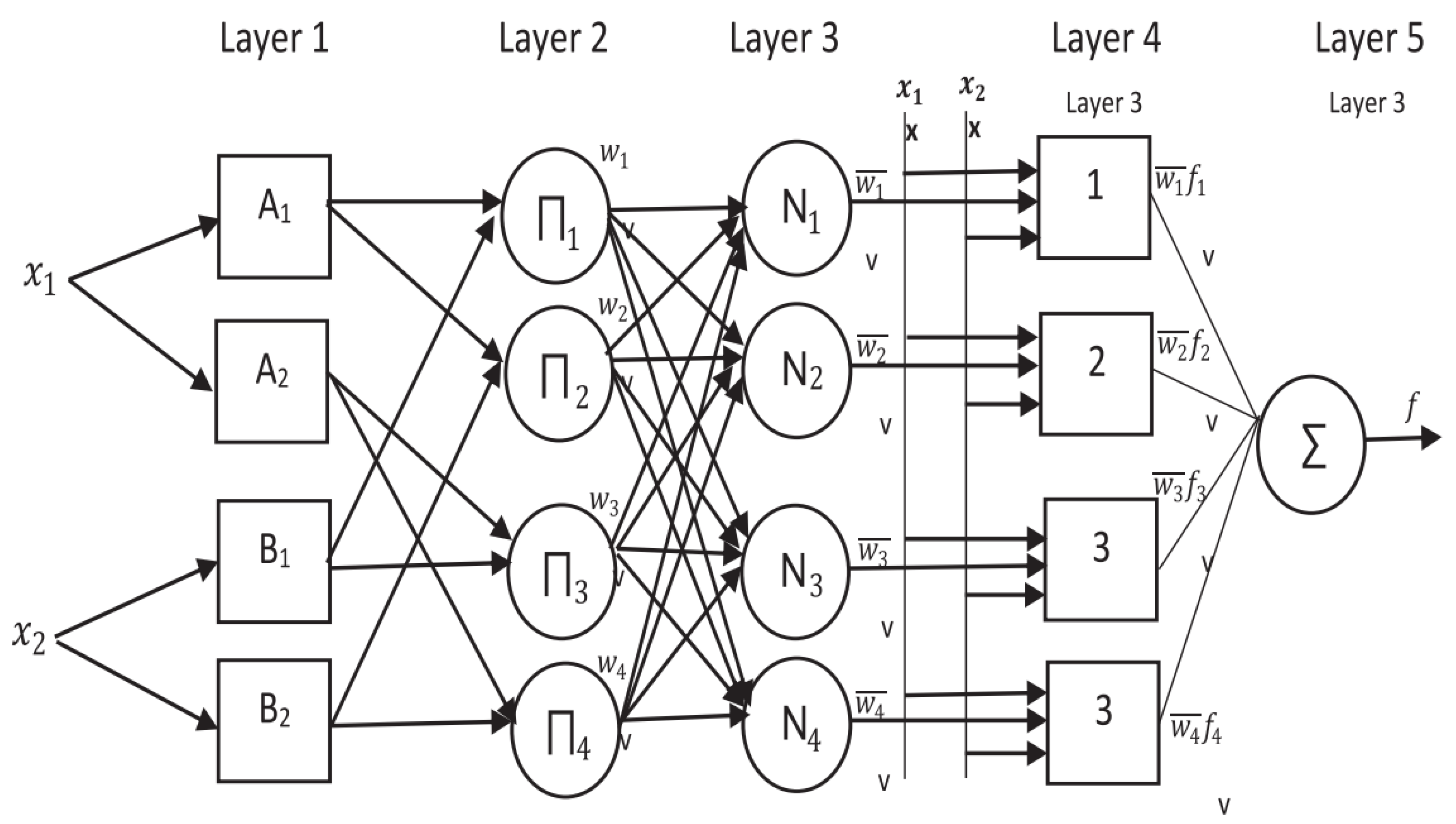
A low-cost intelligent dual-axis solar system proposed by Jamroen et al. [108] utilizes closed-loop active tracking based on light sensors. Using digital logic and a pseudo azimuth system, as depicted in Figure 10 and Figure 11, the solar panels rotate around the main axis (elevation angle) and secondary axis (azimuth angle). The results show a 44.89% increase in energy efficiency compared to fixed systems. Abdollahpour et al. [109] designed a dual-axis solar tracking system employing image processing and shadow analysis. The system comprises shadow projection objects, a network camera, electronic circuits, computer control, and stepper motors to achieve precise tracking, as illustrated in Figure 12. Initially, they captured images of shadows on the solar panel and applied binarization to highlight the shadows. They calibrated the camera to determine the ratio between pixels in the image and actual dimensions (in millimeters). This calibration was achieved by measuring the pixel dimensions of known-sized objects in the image. Subsequently, morphological operators and regression analysis were used to measure the shadow angles. In the morphological approach, they calculated the length of the shadow, i.e., the distance from the image center to the farthest point of the shadow. This length was then used to calculate the panel’s angle by determining the coordinates between the farthest point and the image center. In reference [110], an advanced dual-axis STS was developed using ultraviolet (UV) sensors to overcome the limitations associated with LDR under conditions of light intensity saturation and low visibility. The system’s design involved capturing the UV spectrum through UV sensors. The controller of this system compared signals from four UV sensors, directing actuators to track the Sun’s trajectory. The results demonstrated an 11.00% increase in electricity generation compared to systems employing LDR. Sidek et al. [111] proposed an open-loop automatic tracking dual-axis solar energy system. The system was manufactured using standard cylindrical hollow aluminum and polyethylene. It integrated an astronomical equation and a solar path trajectory algorithm based on Global Positioning System (GPS) information, controlled by a microcontroller along with auxiliary devices, including encoders and a GPS. Furthermore, it employed proportional–integral–derivative control to minimize energy consumption. The tracking accuracy achieved was within ±0.5°, resulting in an energy generation increase of 26.9% in sunny conditions and 12.8% on cloudy days compared to fixed-tilted PV systems. In reference [112], an active dual-axis STS was implemented using minimal components, achieving cost-effectiveness. The results demonstrated a 36.26% increase in energy output compared to fixed systems. In a novel approach, Nadia et al. [113] introduced an intelligent dual-axis ST control system based on the Adaptive Neuro-Fuzzy Inference System (ANFIS) principles, as shown in Figure 13. The system accurately predicted the solar trajectory using the ANFIS to enhance the performance of the dual-axis solar tracker. Experimental data, with input variables of month, date, and time, were utilized to train the model, predicting precise solar positions. The ANFIS model demonstrated robustness and high predictive accuracy in determining the optimal tracking angles under maximum solar radiation. The proposed controller effectively controlled the STS. Al-Amayreh and colleagues presented a hybrid solar lighting/thermal system utilizing a parabolic solar dish as a solar collector. A dual-axis tracker increased collector efficiency, and daylight was transmitted via optical fibers to photovoltaic devices for electricity generation. The system demonstrated cost-effectiveness and high performance [114]. Fathabadi et al. [115] introduced a sensorless dual-axis solar tracker with high accuracy. The system employed a closed-loop control system utilizing Universal Maximum Power Point Tracking (MPPT). Unlike other MPPTs, this system showed an error of 0.11°, enhancing tracking precision. Safan et al. [116] designed a hybrid control system integrating open-loop astronomical algorithms and closed-loop intelligent controllers. It implemented a multi-degree-of-freedom simplified universal integral proportional derivative tracking strategy, achieving tracking errors as low as ±0.18°. Wu et al. [117] proposed a solar tracking system using two GPS receivers equipped with real-time clocks, forming a satellite compass. The system embedded the solar position algorithm to determine solar vector angles based on the provided dates, times, and geographical information from the satellite compass. The system increased energy collection by 35.91% compared to fixed systems on sunny days. Shufat and the team designed a dual-axis STS with a parabolic dish antenna, as illustrated in Figure 14. The system controlled the solar tracker’s driver, gearbox, angular velocity, and mechanical torque using a Programmable Logic Controller (PLC). Two steep motors were designed to guide the parabolic dish panel to stay perpendicular to the solar beam. MATLAB/Simulink environment was utilized to simulate actual solar trajectory angles and direct normal irradiance data. The tracker designed in the study demonstrated flexibility, reliability, and lower costs, requiring no hardware or software modifications during seasonal changes or cloudy days [118]. Reference [119] introduced an intelligent dual-axis STS for remote weather monitoring in agricultural applications. The system aimed to enhance the efficiency of solar panels while providing constant power for sensors in agriculture. The system monitors the positional deviation between the Sun and the photovoltaic panels, automatically adjusting the panels’ orientation along both the horizontal (azimuthal) and vertical (elevation) axes to ensure optimal alignment with the Sun. Through an Android application, users could monitor real-time performance data of the solar system and transfer weather data to the application via GSM/WiFi modules. The research results indicated a potential increase in power generation by up to 52% compared to existing systems. Additionally, the application of intelligent artificial intelligence techniques and quality of service algorithms improved the system’s service quality. As depicted in Figure 15, Jallal et al. [120] designed a novel machine learning model called Deep Neural Networks–Random Distribution Delay Particle Swarm Optimization to enhance the real-time prediction accuracy of hourly energy output in dual-axis solar tracking systems. This system integrated Deep Neural Networks with the Random Distribution Delay Particle Swarm Optimization algorithm. The Random Distribution Delay Particle Swarm Optimization algorithm enhanced the training process of the Deep Neural Networks model by reducing the risk of falling into local optima and increasing the diversity of the search space. The research results showed a significant improvement in prediction accuracy. Table 4 provides an overview of the parameters of recent studies on dual-axis STS(s).
With the continuous advancement of artificial intelligence and machine learning, dual-axis STS(s) will become more intelligent. These systems can utilize machine learning algorithms to predict the position of the Sun and make real-time decisions based on live weather data and lighting conditions, maximizing energy collection efficiency. Moreover, intelligent systems can automatically perform fault detection and maintenance management, reducing downtime. Digital technology will play a crucial role in dual-axis STS(s). Sensor networks and Internet of Things technologies will enable real-time monitoring and collection of vast amounts of data, including solar radiation, temperature, humidity, and other environmental parameters. These data will be used to optimize system performance and for remote monitoring. These systems can help reduce reliance on fossil fuels, decrease greenhouse gas emissions, and drive dual-axis STS(s) to become an integral part of sustainable development.

5. Limiting Factors Affecting the Performance and Efficiency of Solar Tracking Systems

5.1. Cost

Installing a solar tracking system necessitates the purchase of additional hardware, such as electric drives, sensors, controllers, and mechanical structures. The acquisition cost of these components is often considerably high, especially for large-scale solar fields or PV power plants. The installation of STS(s) is more intricate compared to stationary solar systems and requires regular maintenance to ensure the proper functioning of mechanical and electronic components. This maintenance involves tasks such as cleaning, lubrication, fault diagnosis, and repairs. Reference [141] has proposed design concepts for low-cost STS(s) focusing on mechanical structures, installation costs, and maintenance expenses, simultaneously ensuring the system’s tracking efficiency.
Over time, the technology of STS(s) is expected to advance and mature. This may involve more efficient control systems, durable mechanical structures, and cost-effective sensors and electronic components. These technological advancements hold the potential to reduce the manufacturing costs of the systems.

5.2. Geographical Environment and Climatic Conditions

The varying geographical locations on Earth result in significant disparities in both the intensity and trajectory of solar radiation. Regions closer to the equator receive relatively high solar radiation for most of the year, making STS(s) less critical in these areas. However, in regions farther from the equator, especially at higher latitudes, the solar trajectory becomes more inclined. Therefore, this mandates a more sophisticated design and control of STS(s) to accommodate the changing position of the Sun in the sky [142,143,144]. Geographical factors also encompass topography and shading effects, which can influence the angle and intensity of solar radiation reaching a surface. Terrain features such as mountains and buildings may result in certain regions being unable to receive direct sunlight during specific periods, thereby diminishing the efficiency of solar energy systems. The research conducted by Corona et al. [145] reveals notable variations in the hybridization performance of solar energy systems across different countries on a global scale, with differences ranging from 35% to 43%. One primary limiting factor contributing to these variations is the availability of solar radiation in respective locations, as solar radiation determines the energy levels collected by heliostats. There exists a positive correlation between the increased electricity generation of individual functional units and the corresponding reduction in environmental impact. Firozjaei et al. [146] conducted an in-depth investigation into the grid-connected electricity prices for PV generation based on the geographical and climatic conditions of various provinces in Iran. The findings revealed a solar radiation range of 380–578 W/m2 across the entire nation of Iran. Furthermore, distinct variations were observed in the grid-connected electricity prices for PV generation, ranging from 0.0835 to 0.1272 USD, among different regions within the country. Ruiz et al. [147] systematically investigated the potential impact of geographical location on solar power plant siting. Employing a multi-criteria decision analysis based on the Analytic Hierarchy Process, the study integrated satellite and local data within a Geographic Information System for a comprehensive analysis of power plant siting. The research findings indicate that, in West Kalimantan province, 34% of the area is available for the deployment of solar power plants, with restrictions imposed by protected areas. Further calculations using the multi-criteria decision analysis based on the Analytic Hierarchy Process revealed that only 0.03–0.07% of the area possesses optimal conditions for power plant siting.
In high-altitude regions, solar tracking systems optimize the orientation of photovoltaic panels by tracking the movement of the Sun, ensuring optimal reception of radiation. This mitigates the impact of sparse atmosphere and complex terrain on system performance, thereby achieving enhanced energy output [148,149,150,151,152]. The study referenced in the literature [151] investigated the optimal tilt angles for solar collectors in high-altitude regions, taking into account terrain-induced shading factors on solar panels. Experimental results demonstrated that the optimized system, considering both angles and shading, increased the annual and monthly solar energy collection by 9.73% and 16.24%, respectively, compared to the original system that did not account for angles and shading.
Climatic conditions, including temperature, wind speed, cloud cover, and seasonal variations, significantly impact the efficiency of solar tracking systems. Eldin et al. [30] applied a mathematical model to validate the performance of solar panels in cold and hot urban areas, revealing a gain of approximately 39% in cold regions and no more than 8% in hot regions. In a comparative study conducted by Ghazali et al. [153] in the hot and humid climate of Malaysia, efficiency comparisons were made among monocrystalline, polycrystalline, and amorphous silicon solar panels, demonstrating that polycrystalline silicon solar cells exhibited the highest efficiency. Fahad et al. [154] conducted a detailed performance comparison study of three solar tracking systems—fixed, single-axis, and dual-axis—in Bangladesh, taking regional climatic conditions into consideration. In comparison to the fixed-axis tracking system, the annual incident energy for the single-axis tracking system significantly increased by 25–40%, and for the dual-axis tracking system, this increment ranged from 26–45%. On average, the single-axis tracking system generated 32.2% more energy than the fixed-axis tracking system, while the dual-axis tracking system produced 36.8% more energy than the fixed-axis tracking system. Without considering the impact of cloud cover, the dual-axis tracking system exhibited a 3.96% higher annual incident energy than the single-axis tracking system. Kuttybay et al. [155] proposed a simple method for determining the rotation angle of solar trackers based on adjusting sensors related to LDR under different weather conditions. The results demonstrated the feasibility of designing solar trackers under various weather conditions. Martinez-García et al. [156] considered the impact of wind on solar tracking systems, where galloping, an oscillatory phenomenon occurring when wind speeds exceed a critical value known as the flutter critical, induces angular oscillations in the tracker, increasing in amplitude until structural collapse. They explored the inherent relationship between the equations of motion for aerodynamic elasticity and the torque equations in differential form when wind acted on the system and tested the system’s aerodynamic elastic model. Results showed that the flutter critical deceleration speed varied with the tilt angle.
Solar tracking systems should be designed to adapt to various geographical environments, including high-latitude regions, deserts, mountains, coastal areas, etc. In these locations, the trajectory of the Sun and climatic conditions may vary, requiring flexibility in tracking systems to accommodate diverse scenarios. When facing extreme weather conditions, STS(s) need to possess features such as wind resistance, rain protection, and snow resistance. By continuously monitoring the Sun’s position and meteorological conditions, tracking systems can adjust the angles of solar panels in real-time to maximize solar radiation absorption or seek shelter.

6. Conclusions and Prospects

The solar PV tracking system continuously adjusts the angle of solar panels to maximize energy collection throughout the day by tracking the Sun’s position. This article provides a comprehensive review of PV cells made from different materials, with a particular focus on comparing and analyzing their manufacturing processes, performance, and research trends. Based on driving mechanisms and degrees of freedom of motion, the low-cost cases, tracking strategies, control methods, and limiting factors of solar tracking systems are classified and reviewed. Advancements in tracking technology, including sophisticated sensor technology, intelligent control systems, and cloud computing, contribute to improving the performance and reliability of these systems. As economies of scale are realized, and technological costs decrease, the construction and maintenance costs of solar PV tracking systems are gradually decreasing, making solar energy more economically viable. Additionally, the development of more affordable, environmentally friendly, and efficient PV cell materials is a crucial research direction. Combining technological progress with the expansion of solar PV systems in the field of power generation can significantly reduce carbon emissions, contribute to addressing climate change, and mitigate global warming.
In the future, solar PV tracking systems will further enhance energy collection efficiency, including dual-axis tracking systems and systems employing advanced optical technologies. These systems will enable solar panels to track the Sun more accurately and perform exceptionally well under various lighting conditions. Simultaneously, tracking systems will become more intelligent and digitized. By utilizing artificial intelligence, big data analysis, and internet connectivity, the systems can achieve real-time monitoring, fault diagnosis, and remote operation. Solar tracking systems can be applied not only in electricity generation but also in various fields such as agricultural irrigation, water treatment, and integrated energy systems.
In conclusion, solar PV tracking system technology will continue to play a crucial role in the field of sustainable energy, contributing to mitigating climate change, reducing energy costs, and promoting the transition to green energy. With ongoing technological advancements and the expanding market, solar PV tracking systems are expected to achieve broader applications and increased sustainability in the future.

Author Contributions

Z.Y.: formal analysis, writing—original Draft, investigation, writing—review and editing. Z.X.: writing—review and editing. All authors have read and agreed to the published version of the manuscript.

Funding

This research received no external funding.

Data Availability Statement

No new data were created or analyzed in this study. Data sharing is not applicable to this article.

Conflicts of Interest

The authors declare no conflict of interest.

Nomenclature

STS(s)solar tracking system(s)
STsolar tracking
PVphotovoltaic
m-Simonocrystalline silicon
p-Sipolycrystalline silicon
a-Siamorphous silicon
ANFISAdaptive Neuro-Fuzzy Inference System
DCdirect current
CIGScopper indium gallium selenide
DSSCsdye-sensitized solar cells
GaAsGallium arsenide
CdTecadmium telluride
SMAsmart shape memory alloy
LDRlight-dependent resistor
UVultraviolet
GPSGlobal Positioning System
MPPTMaximum Power Point Tracking

References

  1. Zhang, G.; Zeng, G.; Li, C.; Yang, X. Impact of PDO and AMO on interdecadal variability in extreme high temperatures in North China over the most recent 40-year period. Clim. Dyn. 2020, 54, 3003–3020. [Google Scholar] [CrossRef]
  2. King, A.; Karoly, D.; Henley, B. Australian climate extremes at 1.5 °C and 2 °C of global warming. Nat. Clim Chang. 2017, 7, 412–416. [Google Scholar] [CrossRef]
  3. Jacobs, K.L.; Buizer, J.L.; Moser, S.C. The third US national climate assessment: Innovations in science and engagement. Clim. Chang. 2016, 135, 1–7. [Google Scholar] [CrossRef]
  4. Zhang, G.; Zeng, G.; Yang, X.; Jiang, Z. Future Changes in Extreme High Temperature over China at 1.5 °C–5 °C Global Warming Based on CMIP6 Simulations. Adv. Atmos. Sci. 2021, 38, 253–267. [Google Scholar] [CrossRef]
  5. Racharla, S.; Rajan, K. Solar tracking system—A review. Int. J. Sustain. Eng. 2017, 10, 72–81. [Google Scholar] [CrossRef]
  6. Yao, Y.; Hu, Y.; Gao, S.; Yang, G.; Du, J. A multipurpose dual-axis solar tracker with two tracking strategies. Renew. Energy 2014, 72, 88–98. [Google Scholar] [CrossRef]
  7. Finster, C. El heliostato de la Universidad santa maria. Scientia 1962, 119, 5–20. [Google Scholar]
  8. McFee, R.H. Power collection reduction by mirror surface nonflatness and tracking error for a central receiver solar power system. Appl. Opt. 1975, 14, 1493–1502. [Google Scholar] [CrossRef]
  9. Dorian, M.E.; Nelson, D.H. Solar Tracking Device. U.S. Patent No.US 4223214, 16 September 1980. [Google Scholar]
  10. Zulkafli, R.S.; Bawazir, A.S.; Amin, N.A.M.; Hashim, M.S.M.; Majid, M.S.A.; Nasir, N.F.M. Dual axis solar tracking system in Perlis, Malaysia. J. Telecommun. Electron. Comput. Eng. (JTEC) 2018, 10, 91–94. [Google Scholar]
  11. Neagoe, M.; Visa, I.; Burduhos, B.G.; Moldovan, M.D. Thermal load based adaptive tracking for flat plate solar collectors. Energy Procedia 2014, 48, 1401–1411. [Google Scholar] [CrossRef]
  12. Indrasari, W.; Fahdiran, R.; Budi, E.; Jannah, L.L.; Kadarwati, L.V. Active solar tracker based on the horizon coordinate system. In Journal of Physics: Conference Series; IOP Publishing: Bristol, UK, 2018; Volume 1120, No. 1. [Google Scholar]
  13. Awasthi, A.; Shukla, A.K.; SR, M.M.; Dondariya, C.; Shukla, K.N.; Porwal, D.; Richhariya, G. Review on sun tracking technology in solar PV system. Energy Rep. 2020, 6, 392–405. [Google Scholar] [CrossRef]
  14. Sumathi, V.; Jayapragash, R.; Bakshi, A.; Akella, P.K. Solar tracking methods to maximize PV system output—A review of the methods adopted in recent decade. Renew. Sustain. Energy Rev. 2017, 74, 130–138. [Google Scholar] [CrossRef]
  15. Elsherbiny, M.S.; Anis, W.R.; Hafez, I.M.; Mikhail, A.R. Design of single-axis and dual-axis solar tracking systems protected against high wind speeds. Int. J. Sci. Technol. Res. 2017, 6, 84–89. [Google Scholar]
  16. Ferdaus, R.A.; Mohammed, M.A.; Rahman, S.; Salehin, S.; Mannan, M.A. Energy efficient hybrid dual axis solar tracking system. J. Renew. Energy 2014, 2014, 629717. [Google Scholar] [CrossRef]
  17. Singh, R.; Kumar, S.; Gehlot, A.; Pachauri, R. An imperative role of sun trackers in photovoltaic technology: A review. Renew. Sustain. Energy Rev. 2018, 82, 3263–3278. [Google Scholar] [CrossRef]
  18. Roth, P.; Georgiev, A.; Boudinov, H. Design and construction of a system for sun-tracking. Renew. Energy 2004, 29, 393–402. [Google Scholar] [CrossRef]
  19. Abdallah, S.; Nijmeh, S. Two axes sun tracking system with PLC control. Energy Convers. Manag. 2004, 45, 1931–1939. [Google Scholar] [CrossRef]
  20. De Castro, C.; Mediavilla, M.; Miguel, L.J.; Frechoso, F. Global solar electric potential: A review of their technical and sustainable limits. Renew. Sustain. Energy Rev. 2013, 28, 824–835. [Google Scholar] [CrossRef]
  21. Mohamad, A.; Mhamdi, H.; Amin, N.A.M.; Izham, M.; Aziz, N.A.; Chionh, S.Y. A review of automatic solar tracking systems. In Journal of Physics: Conference Series; IOP Publishing: Bristol, UK, 2021; Volume 2051, No. 1. [Google Scholar]
  22. Bayod-Rújula, Á.A.; Lorente-Lafuente, A.M.; Cirez-Oto, F. Environmental assessment of grid connected photovoltaic plants with 2-axis tracking versus fixed modules systems. Energy 2011, 36, 3148–3158. [Google Scholar] [CrossRef]
  23. Balali, M.H.; Nouri, N.; Omrani, E.; Nasiri, A.; Otieno, W. An overview of the environmental, economic, and material developments of the solar and wind sources coupled with the energy storage systems. Int. J. Energy Res. 2017, 41, 1948–1962. [Google Scholar] [CrossRef]
  24. Song, J.; Zhu, Y.; Jin, Z.; Yang, Y. Daylighting system via fibers based on two-stage sun-tracking model. Sol. Energy 2014, 108, 331–339. [Google Scholar] [CrossRef]
  25. Bentaher, H.; Kaich, H.; Ayadi, N.; Hmouda, M.B.; Maalej, A.; Lemmer, U. A simple tracking system to monitor solar PV panels. Energy Convers. Manag. 2014, 78, 872–875. [Google Scholar] [CrossRef]
  26. Gabe, I.J.; Bühler, A.; Chesini, D.; Frosi, F. Design and implementation of a low-cost dual-axes autonomous solar tracker. In Proceedings of the 2017 IEEE 8th International Symposium on Power Electronics for Distributed Generation Systems (PEDG), Florianópolis, Brazil, 17–20 April 2017. [Google Scholar]
  27. Tomson, T. Discrete two-positional tracking of solar collectors. Renew. Energy 2008, 33, 400–405. [Google Scholar] [CrossRef]
  28. Huang, B.J.; Sun, F.S. Feasibility study of one axis three positions tracking solar PV with low concentration ratio reflector. Energy Convers. Manag. 2007, 48, 1273–1280. [Google Scholar] [CrossRef]
  29. Skouri, S.; Ali, A.B.; Bouadila, S.; Salah, M.B.; Nasrallah, S.B. Design and construction of sun tracking systems for solar parabolic concentrator displacement. Renew. Sustain. Energy Rev. 2016, 60, 1419–1429. [Google Scholar] [CrossRef]
  30. Eldin, S.A.S.; Abd-Elhady, M.S.; Kandil, H.A. Feasibility of solar tracking systems for PV panels in hot and cold regions. Renew. Energy 2016, 85, 228–233. [Google Scholar] [CrossRef]
  31. Gorter, T.; Reinders, A.H.M. A comparison of 15 polymers for application in photovoltaic modules in PV-powered boats. Appl. Energy 2012, 92, 286–297. [Google Scholar] [CrossRef]
  32. Green, M.; Dunlop, E.; Hohl-Ebinger, J.; Yoshita, M.; Kopidakis, N.; Hao, X. Solar cell efficiency tables (version 57). Prog. Photovolt. Res. Appl. 2021, 29, 3–15. [Google Scholar] [CrossRef]
  33. Sharma, P.; Goyal, P. Evolution of PV technology from conventional to nano-materials. Mater. Today Proc. 2020, 28, 1593–1597. [Google Scholar] [CrossRef]
  34. Luque, A.; Hegedus, S. (Eds.) Handbook of Photovoltaic Science and Engineering; John Wiley & Sons: Hoboken, NJ, USA, 2011; pp. 5–36. [Google Scholar]
  35. Richter, A.; Hermle, M.; Glunz, S.W. Reassessment of the limiting efficiency for crystalline silicon solar cells. IEEE J. Photovolt. 2013, 3, 1184–1191. [Google Scholar] [CrossRef]
  36. Goetzberger, A.; Hebling, C.; Schock, H.-W. Photovoltaic materials, history, status and outlook. Mater. Sci. Eng. R Rep. 2003, 40, 1–46. [Google Scholar] [CrossRef]
  37. Pastuszak, J.; Węgierek, P. Photovoltaic cell generations and current research directions for their development. Materials 2022, 15, 5542. [Google Scholar] [CrossRef] [PubMed]
  38. Ohl, R.S. Light-Sensitive Electric Device Including Silicon. U.S. Patent No. 2,443,542, 15 June 1948. [Google Scholar]
  39. Luceño-Sánchez, J.A.; Díez-Pascual, A.M.; Capilla, R.P. Materials for photovoltaics: State of art and recent developments. Int. J. Mol. Sci. 2019, 20, 976. [Google Scholar] [CrossRef] [PubMed]
  40. Socol, M.; Preda, N. Hybrid Nanocomposite Thin Films for Photovoltaic Applications: A Review. Nanomaterials 2021, 11, 1117. [Google Scholar] [CrossRef] [PubMed]
  41. Sampaio, P.G.V.; González, M.O.A. Photovoltaic solar energy: Conceptual framework. Renew. Sustain. Energy Rev. 2017, 74, 590–601. [Google Scholar] [CrossRef]
  42. Moon, S.; Kim, K.; Kim, Y.; Heo, J.; Lee, J. Highly Efficient Single-Junction GaAs Thin-Film Solar Cell on Flexible Substrate. Sci. Rep. 2016, 6, 30107. [Google Scholar] [CrossRef] [PubMed]
  43. Irvine, S. Solar Cells and Photovoltaics. In Springer Handbook of Electronic and Photonic Materials; Springer: Cham, Switzerland, 2017. [Google Scholar] [CrossRef]
  44. Chopra, K.L.; Paulson, P.D.; Dutta, V. Thin-film solar cells: An overview. Prog. Photovolt. Res. Appl. 2004, 12, 69–92. [Google Scholar] [CrossRef]
  45. Hishikawa, Y.; Dunlop, E.D.; Green, M.A.; Hohl, J.; Anita, E.; Baillie, W.Y.H.; Levi, D.H. Solar cell efficiency tables (version 50). Prog. Photovolt. 2017, 25, 668–676. [Google Scholar] [CrossRef]
  46. Niki, S.; Contreras, M.; Repins, I.; Powalla, M.; Kushiya, K.; Ishizuka, S.; Matsubara, K. CIGS absorbers and processes. Prog. Photovolt. Res. Appl. 2010, 18, 453–466. [Google Scholar] [CrossRef]
  47. Feurer, T.; Reinhard, P.; Avancini, E.; Bissig, B.; Löckinger, J.; Fuchs, P.; Tiwari, A.N. Progress in thin film CIGS photovoltaics–Research and development, manufacturing, and applications. Prog. Photovolt. Res. Appl. 2017, 25, 645–667. [Google Scholar] [CrossRef]
  48. Gong, J.; Liang, G.; Sumathy, K. Review on dye-sensitized solar cells (DSSCs): Fundamental concepts and novel materials. Renew. Sustain. Energy Rev. 2012, 16, 5848–5860. [Google Scholar] [CrossRef]
  49. Tian, J.; Cao, G. Semiconductor quantum dot-sensitized solar cells. Nano Rev. 2013, 4, 22578. [Google Scholar] [CrossRef] [PubMed]
  50. Kramer, I.J.; Zhitomirsky, D.; Bass, J.D.; Rice, P.M.; Topuria, T.; Krupp, L.; Sargent, E.H. Ordered nanopillar structured electrodes for depleted bulk heterojunction colloidal quantum dot solar cells. Adv. Mater. 2012, 24, 2315–2319. [Google Scholar] [CrossRef] [PubMed]
  51. Jean, J.; Chang, S.; Brown, P.R.; Cheng, J.J.; Rekemeyer, P.H.; Bawendi, M.G.; Bulović, V. ZnO nanowire arrays for enhanced photocurrent in PbS quantum dot solar cells. Adv. Mater. 2013, 25, 2790–2796. [Google Scholar] [CrossRef] [PubMed]
  52. Kim, T.-Y.; Lee, S.; Jeong, D.; Lee, T.K.; Kim, B.S.; Chae, I.S.; Kang, Y.S. Poly (3, 4-ethylenedioxythiophene) quantum dot-sensitized solar cells in the solid-state utilizing polymer electrolyte. ACS Appl. Energy Mater. 2018, 1, 290–295. [Google Scholar] [CrossRef]
  53. Philipps, S.P.; Bett, A.W. III-V Multi-junction solar cells and concentrating photovoltaic (CPV) systems. Adv. Opt. Technol. 2014, 3, 469–478. [Google Scholar] [CrossRef]
  54. Zheng, Q.; Kim, J.K. Synthesis, Structure, and Properties of Graphene and Graphene Oxide. In Graphene for Transparent Conductors; Springer: New York, NY, USA, 2015; Volume 23. [Google Scholar] [CrossRef]
  55. Sun, Y.; Zhang, W.; Chi, H.; Liu, Y.; Hou, C.L.; Fang, D. Recent development of graphene materials applied in polymer solar cell. Renew. Sustain. Energy Rev. 2015, 43, 973–980. [Google Scholar] [CrossRef]
  56. Díez-Pascual, A.M.; Díez-Vicente, A.L. Poly (propylene fumarate)/polyethylene glycol-modified graphene oxide nanocomposites for tissue engineering. ACS Appl. Mater. Interfaces 2016, 8, 17902–17914. [Google Scholar] [CrossRef]
  57. Díez-Pascual, A.M.; Vallés, C.; Mateos, R.; Vera-López, S.; Kinloch, I.A.; San Andrés, M.P. Influence of surfactants of different nature and chain length on the morphology, thermal stability and sheet resistance of graphene. Soft Matter 2018, 14, 6013–6023. [Google Scholar] [CrossRef]
  58. Kumar, A.; Zhou, C. The race to replace tin-doped indium oxide: Which material will win? ACS Nano 2010, 4, 11–14. [Google Scholar] [CrossRef]
  59. Nismy, N.A.; Jayawardena, K.I.; Adikaari, A.D.T.; Silva, S.R.P. Photoluminescence Quenching in Carbon Nanotube-Polymer/Fullerene Films: Carbon Nanotubes as Exciton Dissociation Centres in Organic Photovoltaics. Adv. Mater. 2011, 23, 3796–3800. [Google Scholar] [CrossRef]
  60. Folorunso, O.; Hamam, Y.; Sadiku, R.; Ray, S.S.; Adekoya, G.J. Synthesis methods of borophene, graphene-loaded polypyrrole nanocomposites and their benefits for energy storage applications: A brief overview. FlatChem 2021, 26, 100211. [Google Scholar] [CrossRef]
  61. Deb, G.; Roy, A.B. Use of solar tracking system for extracting solar energy. Int. J. Comput. Electr. Eng. 2012, 4, 42. [Google Scholar] [CrossRef]
  62. Şenpinar, A.; Cebeci, M. Evaluation of power output for fixed and two-axis tracking PVarrays. Appl. Energy 2012, 92, 677–685. [Google Scholar] [CrossRef]
  63. Zhang, P.; Zhou, G.; Zhu, Z.; Li, W.; Cai, Z. Numerical study on the properties of an active sun tracker for solar streetlight. Mechatronics 2013, 23, 1215–1222. [Google Scholar] [CrossRef]
  64. Koussa, M.; Cheknane, A.; Hadji, S.M.H.S.N.; Haddadi, M.; Noureddine, S. Measured and modelled improvement in solar energy yield from flat plate photovoltaic systems utilizing different tracking systems and under a range of environmental conditions. Appl. Energy 2011, 88, 1756–1771. [Google Scholar] [CrossRef]
  65. Ahmad, S.; Shafie, S.; Kadir, M.Z.A.A. Power feasibility of a low power consumption solar tracker. Procedia Environ. Sci. 2013, 17, 494–502. [Google Scholar] [CrossRef]
  66. Perpiñán, O. Cost of energy and mutual shadows in a two-axis tracking PV system. Renew. Energy 2012, 43, 331–342. [Google Scholar] [CrossRef]
  67. Cañada, J.; Utrillas, M.P.; Martinez-Lozano, J.A.; Pedrós, R.; Gómez-Amo, J.L.; Maj, A. Design of a sun tracker for the automatic measurement of spectral irradiance and construction of an irradiance database in the 330–1100 nm range. Renew. Energy 2007, 32, 2053–2068. [Google Scholar] [CrossRef]
  68. Ahmad, S.; Shafie, S.; Ab Kadir, M.Z.A.; Ahmad, N.S. On the effectiveness of time and date-based sun positioning solar collector in tropical climate: A case study in Northern Peninsular Malaysia. Renew. Sustain. Energy Rev. 2013, 28, 635–642. [Google Scholar] [CrossRef]
  69. Yilmaz, S.; Ozcalik, H.R.; Dincer, F. The analysis on the impact of the roof angle on electricity energy generation of photovoltaic panels in Kahramanmaras, Turkey—A case study for all seasons. J. Renew. Sustain. Energy 2015, 7, 023133. [Google Scholar] [CrossRef]
  70. Yilmaz, S.; Ozcalik, H.R.; Dogmus, O.; Dincer, F.; Akgol, O.; Karaaslan, M. Design of two axes sun tracking controller with analytically solar radiation calculations. Renew. Sustain. Energy Rev. 2015, 43, 997–1005. [Google Scholar] [CrossRef]
  71. Sun, L.; Lu, L.; Yang, H. Optimum design of shading-type building-integrated photovoltaic claddings with different surface azimuth angles. Appl. Energy 2012, 90, 233–240. [Google Scholar] [CrossRef]
  72. Cruz-Peragón, F.; Casanova-Peláez, P.J.; Díaz, F.A.; López-García, R.; Palomar, J.M. An approach to evaluate the energy advantage of two axes solar tracking systems in Spain. Appl. Energy 2011, 88, 5131–5142. [Google Scholar] [CrossRef]
  73. Talebizadeh, P.; Mehrabian, M.A.; Abdolzadeh, M. Prediction of the optimum slope and surface azimuth angles using the Genetic Algorithm. Energy Build. 2011, 43, 2998–3005. [Google Scholar] [CrossRef]
  74. Poulek, V. Testing the new solar tracker with shape memory alloy actors. In Proceedings of the 1994 IEEE 1st World Conference on Photovoltaic Energy Conversion-WCPEC (A Joint Conference of PVSC, PVSEC and PSEC), Waikoloa, HI, USA, 5–9 December 1994; Volume 1. [Google Scholar] [CrossRef]
  75. Dandu, S.C.R.; Sarla, A. Sun Tracking System. 2022. [Google Scholar]
  76. Clifford, M.J.; Eastwood, D. Design of a novel passive solar tracker. Sol. Energy 2004, 77, 269–280. [Google Scholar] [CrossRef]
  77. Ganesh, N.J.; Maniprakash, S.; Chandrasekaran, L.; Srinivasan, S.M.; Srinivasa, A.R. Design and Development of a Sun Tracking Mechanism Using the Direct SMA Actuation. J. Mech. Des. 2011, 133, 075001. [Google Scholar] [CrossRef]
  78. Pen, E.F. Energy efficiency of photovoltaic panels when using holographic gratings as passive solar trackers. Optoelectron. Instrum. Data Process. 2019, 55, 271–279. [Google Scholar] [CrossRef]
  79. Brito, M.C.; Pó, J.M.; Pereira, D.; Simões, F.; Rodriguez, R.; Amador, J.C. Passive solar tracker based in the differential thermal expansion of vertical strips. J. Renew. Sustain. Energy 2019, 11, 043701. [Google Scholar] [CrossRef]
  80. Alemayehu, M.; Admasu, B.T. Passive solar tracker using a bimetallic strip activator with an integrated night return mechanism. Heliyon 2023, 9, e18174. [Google Scholar] [CrossRef]
  81. Abdelghani-Idrissi, M.A.; Khalfallaoui, S.; Seguin, D.; Vernières-Hassimi, L.; Leveneur, S. Solar tracker for enhancement of the thermal efficiency of solar water heating system. Renew. Energy 2018, 119, 79–94. [Google Scholar] [CrossRef]
  82. Stefenon, S.F.; Kasburg, C.; Freire, R.Z.; Silva Ferreira, F.C.; Bertol, D.W.; Nied, A. Photovoltaic power forecasting using wavelet Neuro-Fuzzy for active solar trackers. J. Intell. Fuzzy Syst. 2021, 40, 1083–1096. [Google Scholar] [CrossRef]
  83. Helwa, N.H.; Bahgat, A.B.G.; El Shafee, A.M.R.; El Shenawy, E.T. Maximum collectable solar energy by different solar tracking systems. Energy Sources 2000, 22, 23–34. [Google Scholar]
  84. Mehdi, G.; Ali, N.; Hussain, S.; Zaidi, A.A.; Shah, A.H.; Azeem, M.M. Design and fabrication of automatic single axis solar tracker for solar panel. In Proceedings of the 2019 2nd International Conference on Computing, Mathematics and Engineering Technologies (iCoMET), Sukkur, Pakistan, 30–31 January 2019. [Google Scholar] [CrossRef]
  85. Gutiérrez, S.; Rodrigo, P.M. Energetic analysis of simplified 2-position and 3-position North-South horizontal single-axis sun tracking concepts. Sol. Energy 2017, 157, 244–250. [Google Scholar] [CrossRef]
  86. Rani, P.; Singh, O.; Pandey, S. An analysis on arduino based single axis solar tracker. In Proceedings of the 2018 5th IEEE Uttar Pradesh Section International Conference on Electrical, Electronics and Computer Engineering (UPCON), Gorakhpur, India, 2–4 November 2018. [Google Scholar] [CrossRef]
  87. Munanga, P.; Chinguwa, S.; Nyemba, W.R.; Mbohwa, C. Design for manufacture and assembly of an intelligent single axis solar tracking system. Procedia CIRP 2020, 91, 571–576. [Google Scholar] [CrossRef]
  88. Zhu, Y.; Liu, J.; Yang, X. Design and performance analysis of a solar tracking system with a novel single-axis tracking structure to maximize energy collection. Appl. Energy 2020, 264, 114647. [Google Scholar] [CrossRef]
  89. AL-Rousan, N.; Mat Isa, N.A.; Mat Desa, M.K.; AL-Najjar, H. Integration of logistic regression and multilayer perceptron for intelligent single and dual axis solar tracking systems. Int. J. Intell. Syst. 2021, 36, 5605–5669. [Google Scholar] [CrossRef]
  90. AL-Rousan, N.; Isa, N.A.M.; Desa, M.K.M. Correlation analysis and MLP/CMLP for optimum variables to predict orientation and tilt angles in intelligent solar tracking systems. Int. J. Energy Res. 2021, 45, 453–477. [Google Scholar] [CrossRef]
  91. Sharath, B.N.; Madhu, K.S.; Pradeep, D.G.; Madhu, P.; Premkumar, B.G.; Karthik, S. Conjectured hybrid power with artificial intelligence and single-axis solar tracking wind turbine. Int. J. Energy Water Resour. 2023. [Google Scholar] [CrossRef]
  92. Huang, B.; Huang, J.; Xing, K.; Liao, L.; Xie, P.; Xiao, M.; Zhao, W. Development of a Solar-Tracking System for Horizontal Single-Axis PV Arrays Using Spatial Projection Analysis. Energies 2023, 16, 4008. [Google Scholar] [CrossRef]
  93. Katrandzhiev, N.T.; Karnobatev, N.N. Algorithm for single axis solar tracker. In Proceedings of the 2018 IEEE XXVII International Scientific Conference Electronics-ET, Sozopol, Bulgaria, 13–15 September 2018. [Google Scholar] [CrossRef]
  94. de Sá Campos, M.H.; Tiba, C. npTrack: A n-position single axis solar tracker model for optimized energy collection. Energies 2021, 14, 925. [Google Scholar] [CrossRef]
  95. Kumba, K.; Simon, S.P.; Sundareswaran, K.; Nayak, P.S.R.; Kumar, K.A.; Padhy, N.P. Performance Evaluation of a Second-Order Lever Single Axis Solar Tracking System. IEEE J. Photovolt. 2022, 12, 1219–1229. [Google Scholar] [CrossRef]
  96. Elsayed, A.A.; Khalil, E.E.; Kassem, M.A.; Huzzayin, O.A. A novel mechanical solar tracking mechanism with single axis of tracking for developing countries. Renew. Energy 2021, 170, 1129–1142. [Google Scholar] [CrossRef]
  97. Rinaldi, R.; Aprillia, B.S.; Ekaputri, C.; Reza, M. Design of open loop single axis solar tracker system. In IOP Conference Series: Materials Science and Engineering; IOP Publishing: Bristol, UK, 2020; Volume 982, No. 1. [Google Scholar]
  98. Pulungan, A.B.; Risfendra, R.; Purwanto, W.; Maksum, H.; Setiawan, O. Design and development of real time monitoring single axis solar tracker by using internet of things. Int. J. Geomate 2020, 18, 81–87. [Google Scholar] [CrossRef]
  99. Alvarado-M, J.F.; Betancur, E.; Velásquez-Lopez, A. Optimization of single-axis discrete solar tracking. In Proceedings of the 2020 9th International Conference on Renewable Energy Research and Application (ICRERA), Glasgow, UK, 27–30 September 2020. [Google Scholar] [CrossRef]
  100. Jadli, U.; Uniyal, S.; Uniyal, I. Design of a Single-Axis Solar Tracker Using LDRs. In Intelligent Communication, Control and Devices: Proceedings of ICICCD 2017; Springer: Singapore, 2018. [Google Scholar] [CrossRef]
  101. Maarof, H.A. Influence of Micro-Controller-Based Single Axis Solar Tracker System on Solar Panel’s Performance: Case Study. NTU J. Renew. Energy 2022, 3, 33–43. [Google Scholar]
  102. Abhilash, P.; Kumar, R.N.; Kumar, R.P. Solar powered water pump with single axis tracking system for irrigation purpose. Mater. Today Proc. 2021, 39, 553–557. [Google Scholar] [CrossRef]
  103. Kumar, D.H.; Krishna, R.; Kumar, M.D.; Pradhan, R.; Sreenivasan, M. Harvesting energy from moving vehicles with single-axis solar tracking assisted hybrid wind turbine. Mater. Today Proc. 2020, 33, 326–332. [Google Scholar] [CrossRef]
  104. Almajali, Z.S.; Aldmour, S.A. Single-Axis Solar Tracker System for Maintaining Southward Orientation of Solar Cells in Solar Cars. In Proceedings of the 2023 IEEE Jordan International Joint Conference on Electrical Engineering and Information Technology (JEEIT), Amman, Jordan, 22–24 May 2023. [Google Scholar] [CrossRef]
  105. Zhang, X.; Ma, W.; Zhang, Z.; Hu, L.; Cui, Y. Experimental study on the interference effect of the wind-induced large torsional vibration of single-axis solar tracker arrays. J. Wind. Eng. Ind. Aerodyn. 2023, 240, 105470. [Google Scholar] [CrossRef]
  106. Kher, V.; Sharma, S.; Santhosh, H.M.; Manoj, N.; Yogesh, O.M.; Bhinge, N.A. Scheduled single axis solar tracker system for improvisation of energy efficiency. In Proceedings of the 2022 4th International Conference on Smart Systems and Inventive Technology (ICSSIT), Tirunelveli, India, 20–22 January 2022. [Google Scholar]
  107. Saputra, I.D.; Sajayasa, I.M.; Suryawan, I.K.; Sugirianta, I.; Purbhawa, I.M.; Putra, I.M.E. A New Approach in Controlling A Single Axis Solar Tracker Based on Photovoltaic Output. In Proceedings of the 2021 7th International Conference on Electrical, Electronics and Information Engineering (ICEEIE), Malang, Indonesia, 2 October 2021. [Google Scholar] [CrossRef]
  108. Jamroen, C.; Komkum, P.; Kohsri, S.; Himananto, W.; Panupintu, S.; Unkat, S. A low-cost dual-axis solar tracking system based on digital logic design: Design and implementation. Sustain. Energy Technol. Assess. 2020, 37, 100618. [Google Scholar] [CrossRef]
  109. Abdollahpour, M.; Golzarian, M.R.; Rohani, A.; Zarchi, H.A. Development of a machine vision dual-axis solar tracking system. Sol. Energy 2018, 169, 136–143. [Google Scholar] [CrossRef]
  110. Jamroen, C.; Fongkerd, C.; Krongpha, W.; Komkum, P.; Pirayawaraporn, A.; Chindakham, N. A novel UV sensor-based dual-axis solar tracking system: Implementation and performance analysis. Appl. Energy 2021, 299, 117295. [Google Scholar] [CrossRef]
  111. Sidek, M.H.M.; Azis, N.; Hasan, W.Z.W.; Ab Kadir, M.Z.A.; Shafie, S.; Radzi, M.A.M. Automated positioning dual-axis solar tracking system with precision elevation and azimuth angle control. Energy 2017, 124, 160–170. [Google Scholar] [CrossRef]
  112. Hammoumi, A.E.; Motahhir, S.; Ghzizal, A.E.; Chalh, A.; Derouich, A. A simple and low-cost active dual-axis solar tracker. Energy Sci. Eng. 2018, 6, 607–620. [Google Scholar] [CrossRef]
  113. Nadia, A.-R.; Isa, N.A.M.; Desa, M.K.M. Efficient single and dual axis solar tracking system controllers based on adaptive neural fuzzy inference system. J. King Saud Univ.-Eng. Sci. 2020, 32, 459–469. [Google Scholar] [CrossRef]
  114. Al-Amayreh, M.I.; Alahmer, A. On improving the efficiency of hybrid solar lighting and thermal system using dual-axis solar tracking system. Energy Rep. 2022, 8, 841–847. [Google Scholar] [CrossRef]
  115. Fathabadi, H. Novel high accurate sensorless dual-axis solar tracking system controlled by maximum power point tracking unit of photovoltaic systems. Appl. Energy 2016, 173, 448–459. [Google Scholar] [CrossRef]
  116. Safan, Y.M.; Shaaban, S.; El-Sebah, M.I.A. Performance evaluation of a multi-degree of freedom hybrid controlled dual axis solar tracking system. Sol. Energy 2018, 170, 576–585. [Google Scholar] [CrossRef]
  117. Wu, C.-H.; Wang, H.-C.; Chang, H.-Y. Dual-axis solar tracker with satellite compass and inclinometer for automatic positioning and tracking. Energy Sustain. Dev. 2022, 66, 308–318. [Google Scholar] [CrossRef]
  118. Shufat, S.; Kurt, E.; Hançerlioğullari, A. Modeling and design of azimuth-altitude dual axis solar tracker for maximum solar energy generation. Int. J. Renew. Energy Dev.-IJRED 2019, 8, 7–13. [Google Scholar] [CrossRef]
  119. Kanwal, T.; Rehman, S.U.; Ali, T.; Mahmood, K.; Villar, S.G.; Lopez, L.A.D.; Ashraf, I. An Intelligent Dual-Axis Solar Tracking System for Remote Weather Monitoring in the Agricultural Field. Agriculture 2023, 13, 1600. [Google Scholar] [CrossRef]
  120. Jallal, M.A.; Chabaa, S.; Zeroual, A. A novel deep neural network based on randomly occurring distributed delayed PSO algorithm for monitoring the energy produced by four dual-axis solar trackers. Renew. Energy 2020, 149, 1182–1196. [Google Scholar] [CrossRef]
  121. Hoffmann, F.M.; Molz, R.F.; Kothe, J.V.; Nara, E.O.B.; Tedesco, L.P.C. Monthly profile analysis based on a two-axis solar tracker proposal for photovoltaic panels. Renew. Energy 2018, 115, 750–759. [Google Scholar] [CrossRef]
  122. Sawant, A.; Bondre, D.; Joshi, A.; Tambavekar, P.; Deshmukh, A. Design and analysis of automated dual axis solar tracker based on light sensors. In Proceedings of the 2018 2nd International Conference on I-SMAC (IoT in Social, Mobile, Analytics and Cloud) (I-SMAC)), Palladam, India, 30–31 August 2018. [Google Scholar] [CrossRef]
  123. Mustafa, F.I.; Shakir, S.; Mustafa, F.F.; Naiyf, A.T. Simple design and implementation of solar tracking system two axis with four sensors for Baghdad city. In Proceedings of the 2018 9th International Renewable Energy Congress (IREC), Hammamet, Tunisia, 20–22 March 2018. [Google Scholar] [CrossRef]
  124. Saeedi, M.; Effatnejad, R. A new design of dual-axis solar tracking system with LDR sensors by using the wheatstone bridge circuit. IEEE Sens. J. 2021, 21, 14915–14922. [Google Scholar] [CrossRef]
  125. Amadi, H.N.; Gutiérrez, S. Design and performance evaluation of a dual-axis solar tracking system for rural applications. Eur. J. Electr. Eng. Comput. Sci. 2019, 3, 1. [Google Scholar] [CrossRef]
  126. Taheri, A.; Malayjerdi, M.; Kazemi, M.; Kalani, H.; Nemati-Farouji, R.; Passandideh-Fard, M.; Sardarabadi, M. Improving the performance of a nanofluid-based photovoltaic thermal module utilizing dual-axis solar tracker system: Experimental examination and thermodynamic analysis. Appl. Therm. Eng. 2021, 196, 117178. [Google Scholar] [CrossRef]
  127. Ahmed, R.; Oh, S.J.; Mehmood, M.U.; Kim, Y.; Jeon, G.; Han, H.J.; Lim, S.H. Computer vision and photosensor based hybrid control strategy for a two-axis solar tracker-Daylighting application. Sol. Energy 2021, 224, 175–183. [Google Scholar] [CrossRef]
  128. Vargas, A.N.; Francisco, G.R.; Montezuma, M.A.; Sampaio, L.P.; Acho, L. Low-cost dual-axis solar tracker with photovoltaic energy processing for education. Sustain. Energy Technol. Assess. 2022, 53, 102542. [Google Scholar] [CrossRef]
  129. Pawar, P.; Pawale, P.; Nagthane, T.; Thakre, M.; Jangale, N. Performance enhancement of dual axis solar tracker system for solar panels using proteus ISIS 7.6 software package. Glob. Transit. Proc. 2021, 2, 455–460. [Google Scholar] [CrossRef]
  130. Hamad, B.A.; Ibraheem, A.M.T.; Abdullah, A.G. Design and Practical Implementation of Dual-Axis Solar Tracking System with Smart Monitoring System. Prz. Elektrotechniczny 2020, 1, 153–157. [Google Scholar] [CrossRef]
  131. Gaeid, K.S.; Uddin, M.N.; Mohamed, M.K.; Mohmmoud, O.N. Design and implement of dual axis solar tracker system based arduino. Tikrit J. Eng. Sci. 2020, 27, 71–81. [Google Scholar] [CrossRef]
  132. Fernández-Ahumada, L.M.; Ramírez-Faz, J.; López-Luque, R.; Varo-Martínez, M.; Moreno-García, I.M.; De La Torre, F.C. Influence of the design variables of photovoltaic plants with two-axis solar tracking on the optimization of the tracking and backtracking trajectory. Sol. Energy 2020, 208, 89–100. [Google Scholar] [CrossRef]
  133. Karabiber, A.; Güneş, Y. Single-motor and dual-axis solar tracking system for micro photovoltaic power plants. J. Sol. Energy Eng. 2023, 145, 051004. [Google Scholar] [CrossRef]
  134. Saifuzzaman, M.; Shetu, S.F.; Moon, N.N.; Nur, F.N.; Ali, M.H. IoT based street lighting using dual axis solar tracker and effective traffic management system using deep learning: Bangladesh context. In Proceedings of the 2020 11th International Conference on Computing, Communication and Networking Technologies (ICCCNT), Kharagpur, India, 1–3 July 2020. [Google Scholar] [CrossRef]
  135. Badr, F.; Radwan, A.; Ahmed, M.; Hamed, A.M. Performance assessment of a dual-axis solar tracker for concentrator photovoltaic systems. Int. J. Energy Res. 2022, 46, 13424–13440. [Google Scholar] [CrossRef]
  136. Saymbetov, A.; Mekhilef, S.; Kuttybay, N.; Nurgaliyev, M.; Tukymbekov, D.; Meiirkhanov, A.; Svanbayev, Y. Dual-axis schedule tracker with an adaptive algorithm for a strong scattering of sunbeam. Sol. Energy 2021, 224, 285–297. [Google Scholar] [CrossRef]
  137. Gavaskar, K.; Ragupathy, U.S. New approach for improving the performance of dual axis solar tracker with auto cleaning system. Soft Comput. 2023, 27, 18765–18773. [Google Scholar] [CrossRef]
  138. Prakash, M.B.; Govindarajulu, K. Analysis and Testing of Dual Axis Solar Tracker for Standalone PV Systems Using Worm Gear. Int. J. Mod. Trends Sci. Technol. 2022, 8, 1–8. [Google Scholar] [CrossRef]
  139. Nazri, M.S.M.; Rozlan, M.H.H.M. Development of dual axis solar tracker with IoT monitoring system. J. Eng. Technol. 2022, 10, 156–162. [Google Scholar]
  140. Rosyadah, M.; Kusumanto, R.; Dewi, T. Smart optimization of PV panel output using Fuzzy Logic Controller based solar tracker. Sinergi 2022, 26, 73–80. [Google Scholar] [CrossRef]
  141. Chowdhury, M.E.H.; Khandakar, A.; Hossain, B.; Abouhasera, R. A low-cost closed-loop solar tracking system based on the sun position algorithm. J. Sens. 2019, 2019, 3681031. [Google Scholar] [CrossRef]
  142. Bazyari, S. A study on the effects of solar tracking systems on the performance of photovoltaic power plants. J. Power Energy Eng. 2014, 2, 718. [Google Scholar] [CrossRef]
  143. Zheng, J.; Yan, J.; Pei, J.; Liu, G. Solar tracking error analysis of fresnel reflector. Sci. World J. 2014, 2014, 834392. [Google Scholar] [CrossRef]
  144. Nuwayhid, R.Y.; Mrad, F.; Abu-Said, R.J.R.E. The realization of a simple solar tracking concentrator for university research applications. Renew. Energy 2001, 24, 207–222. [Google Scholar] [CrossRef]
  145. Corona, B.; Ruiz, D.; Miguel, G.S. Life cycle assessment of a HYSOL concentrated solar power plant: Analyzing the effect of geographic location. Energies 2016, 9, 413. [Google Scholar] [CrossRef]
  146. Firozjaei, H.K.; Firozjaei, M.K.; Nematollahi, O.; Kiavarz, M.; Alavipanah, S.K. On the effect of geographical, topographic and climatic conditions on feed-in tariff optimization for solar photovoltaic electricity generation: A case study in Iran. Renew. Energy 2020, 153, 430–439. [Google Scholar] [CrossRef]
  147. Ruiz, H.S.; Sunarso, A.; Ibrahim-Bathis, K.; Murti, S.A.; Budiarto, I. GIS-AHP Multi Criteria Decision Analysis for the optimal location of solar energy plants at Indonesia. Energy Rep. 2020, 6, 3249–3263. [Google Scholar] [CrossRef]
  148. Larico, E.R.A.; Gutierrez, A.C. Solar tracking system with photovoltaic cells: Experimental analysis at high altitudes. Int. J. Renew. Energy Dev. 2022, 11, 630. [Google Scholar] [CrossRef]
  149. Eyring, N.; Kittner, N. High-resolution electricity generation model demonstrates suitability of high-altitude floating solar power. iScience 2022, 25, 104394. [Google Scholar] [CrossRef]
  150. Karpić, J.; Sharma, E.; Khatib, T.; Elmenreich, W. Comparison of solar power measurements in alpine areas using a mobile dual-axis tracking system. Energy Inform. 2019, 2, 1–14. [Google Scholar] [CrossRef]
  151. Xu, L.; Long, E.; Wei, J.; Cheng, Z.; Zheng, H. A new approach to determine the optimum tilt angle and orientation of solar collectors in mountainous areas with high altitude. Energy 2021, 237, 121507. [Google Scholar] [CrossRef]
  152. Zhu, W.; Zhang, B.; Zhang, L.; Xu, Y.; Yang, K. Spatial path analysis for high-altitude solar-powered airship with maximum net energy. Aerosp. Sci. Technol. 2021, 117, 106922. [Google Scholar] [CrossRef]
  153. Ghazali, A.M.; Rahman, A.M.A. The performance of three different solar panels for solar electricity applying solar tracking device under the Malaysian climate condition. Energy Environ. Res. 2012, 2, 235. [Google Scholar] [CrossRef]
  154. Fahad, H.M.; Islam, A.; Islam, M.; Hasan, M.F.; Brishty, W.F.; Rahman, M.M. Comparative analysis of dual and single axis solar tracking system considering cloud cover. In Proceedings of the 2019 International Conference on Energy and Power Engineering (ICEPE), Dhaka, Bangladesh, 14–16 March 2019. [Google Scholar] [CrossRef]
  155. Kuttybay, N.; Saymbetov, A.; Mekhilef, S.; Nurgaliyev, M.; Tukymbekov, D.; Dosymbetova, G.; Svanbayev, Y. Optimized single-axis schedule solar tracker in different weather conditions. Energies 2020, 13, 5226. [Google Scholar] [CrossRef]
  156. Martínez-García, E.; Blanco-Marigorta, E.; Gayo, J.P.; Navarro-Manso, A. Influence of inertia and aspect ratio on the torsional galloping of single-axis solar trackers. Eng. Struct. 2021, 243, 112682. [Google Scholar] [CrossRef]
Figure 1. Solar radiation angle diagram [62,63,64,65,66].
Energies 16 07768 g001
Figure 2. A passive solar tracker is implemented by employing two identical cylindrical tubes filled with a fluid under partial pressure [76].
Energies 16 07768 g002
Figure 3. (a) The working principle of smart solar tracking mechanism. (b) The components of the smart solar tracking mechanism include the following: 1. Shape memory alloy spring. 2. Fixed frame. 3. Pulley mechanism. 4. Wheels. 5. Ratchet and pawl. 6. Main shaft. 7. Locking device. 8. Drive bevel gear. 9. Driven umbrella gear. 10. Mechanism’s own weight. 11. Solar receiver shaft. 12. Lens. 13. Actuator’s own weight. 14. Solar receptor [77].
Energies 16 07768 g003
Figure 4. (a) The voltage reading comparison between single-axis tracking systems and fixed systems. (b) The current reading comparison between single-axis tracking systems and fixed systems. (c) The power reading comparison between single-axis tracking systems and fixed systems [84].
Energies 16 07768 g004
Figure 5. (a) Model of the tracker; (b) manufactured prototype [87].
Energies 16 07768 g005
Figure 6. Comparison of output power between fixed systems and single-axis tracking systems [87].
Energies 16 07768 g006
Figure 7. Schematic diagram of tracking system: (a) morning; (b) noon; (c) afternoon [88].
Energies 16 07768 g007
Figure 8. Solar tracking system diagram based on cascaded multi-layer perceptron (CMLP) and multi-layer perceptron (MLP) [89].
Energies 16 07768 g008
Figure 9. Process diagram for selecting optimal clustering algorithm in solar tracking system based on cascaded multi-layer perceptron and multi-layer perceptron [89].
Energies 16 07768 g009
Figure 10. The rotational axes of the dual-axis tracking system [108].
Energies 16 07768 g010
Figure 11. Rotation angles of each axis: (a) primary axis; (b) secondary axis [108].
Energies 16 07768 g011
Figure 12. (ac) represent gradual rotations to orient the panel towards the Sun, as well as the shadow side of the object [109].
Energies 16 07768 g012
Figure 13. The overall architecture of the Adaptive Neuro-Fuzzy Inference System [113].
Energies 16 07768 g013
Figure 14. The parabolic antenna diagram of the dual-axis solar tracking system [118].
Energies 16 07768 g014
Figure 15. Deep Neural Networks–Random Distribution Delay Particle Swarm Optimization model architecture diagram [120].
Energies 16 07768 g015
Table 2. Solar radiation and related angles for trackers.
NumberParametersFormulasCommentsTerminologiesReferences
1Coefficient of Correction f = 1 + 0.033   cos 360 n 365 Coefficient of correction for solar constantn takes values from 1 to 365, representing the days.[28]
2Declination Angle δ = 23.45 × sin 360 n + 284 365 The angle between the plane of the Earth’s equator and the line connecting the Sun and the Earth’s centern takes values from 1 to 365, representing the days.[62]
3Elevation Angle α s = sin 1 cos Φ cos δ cos ω + sin Φ sin δ The angle between the Sun’s rays and the horizon ω represents the hour angle, calculated as minutes divided by 4. In this formula, negative values are used for minutes before noon and positive values for minutes after noon. Φ represents the latitude of the region[63,64]
4Azimuth Angle γ s = cos 1 sin ( α s ) sin Φ sin δ cos ( α s ) cos Φ The angle measured clockwise from the north along the horizon δ represents the solar declination angle[65]
5Incident Angle θ = cos 1 [ sin δ sin Φ cos β sin ( δ ) cos Φ sin β + cos δ cos Φ cos β cos ω + cos δ sin Φ cos β cos ω + cos δ sin β sin γ sin ω ] The angle between the surface normal and the incoming sunlight β represents the tilt angle[66]
6Radiation Intensity H = 1353 × 1 + 0.33   cos 360 × n 365 × cos θ z 1353   W / m 2 is the Solar constant[67]
7Maximum Radiation Intensity H n = H   cos ( θ z ) [68]
8Radiation Intensity Vertical to the Photovoltaic Panel H b = H n cos θ = R b × H R b represents the ratio of radiation intensity perpendicular to the photovoltaic panel to the radiation intensity reaching the horizontal plane,
R b = H b H = cos θ cos ( θ z )
[68]
9Diffuse Radiation Intensity on Tilted Surface H d . p = H d 1 + cos β 2 H d represents the diffuse radiation intensity, H d = K y × H [69]
10Diffuse Radiation Factor K y = 1.390 4.027 K T + 5.31 K T 2 3.108 K T 3 K T represents the coefficient of ratio between the radiation intensity reaching a horizontal surface and the maximum radiation intensity,   K T = H H n [70]
11The Radiation Intensity Reflected Back from the Photovoltaic Panel H g r = H + H d 1 cos β 2 ρ g ρ g represents the surface reflectance of the photovoltaic panel[71]
12Total Radiation Intensity H T = H b + H d . p + H g r [72,73]
Table 3. Overview of recent research on single-axis solar tracking systems.
System DescriptionConclusionReferences
The design of a sensorless tracking system composed of three modes.Increased output power compared to fixed systems.Katrandzhiev et al. (2018) [93]
The distinctive feature of this system is its model based on single-axis configuration with inner angle deviation control.This model achieves 96.5% energy gain compared to dual-axis tracking systems.de Sá Campos et al. (2021) [94]
The system utilizes the second-order lever principle, avoiding the need for external motors for axial movement of the solar panels.Compared to traditional single-axis tracking systems, it achieves higher efficiency.Kumba et al. (2022) [95]
The distinctive feature of this system is that it requires no electricity, electronic components, or special materials.
The tracking mechanism utilizes wind energy at night, using stored potential energy as its driving force.
The arithmetic mean of the absolute tracking accuracy throughout the year is less than 0.5°, with a standard deviation less than 0.75°.Elsayed et al. (2021) [96]
The system features the use of an Android application-based monitoring interface.The average power output is increased by over 25% compared to the fixed PV system.Rinaldi et al. (2020) [97]
The system features real-time monitoring of the single-axis solar tracker using the Internet of Things.All data can be sent normally and monitored online directly.Pulungan et al. (2020) [98]
The system features the subdivision of angular range into discrete angles, calculated for each angle based on the assumed clear-sky model irradiance.An energy gain between 22.9% and 31.9% was achieved compared to fixed tilted panels.Alvarado-M et al. (2020) [99]
Low cost.Effective tracking implementation.Jadli et al. (2018) [100]
The system is based on Arduino and LDRs.The efficiency is improved by 55.2% compared to fixed solar panels.Maarof and Hiwa Abdlla. (2022) [101]
The system utilizes an intelligent single-axis solar tracking system to power the water pump.Provides a more economical solution.Abhilash et al. (2021) [102]
The system utilizes a single-axis solar tracking system to assist a hybrid wind turbine in harvesting energy from moving vehicles.The feasibility of harvesting energy from moving vehicles on highways was demonstrated.Kumar et al. (2020) [103]
The system features the idea of implementing solar trackers in solar vehicles.It can enhance the energy collection of the system.Almajali et al. (2023) [104]
Wind tunnel anti-interference testing of single-axis ST array.Elucidating the disturbance characteristics and mechanisms of torsional vibrations in single-axis ST array under wind conditions.Zhang et al. (2023) [105]
The system relies on the polar coordinates of the Sun at different positions and time intervals, implementing a planned tracking of the Sun’s position in the sky.During the peak periods of solar maximization, a constant power gain curve was obtained.Kher et al. (2022) [106]
The system employs a novel strategy to find the optimal energy collection.Reduced the energy supply for motors.Saputra et al. (2021) [107]
Table 4. Overview of recent research on dual-axis solar tracking systems.
System DescriptionConclusionReferences
The system has low maintenance costs and can be installed in remote areas.Compared to fixed systems, the tracking system achieves an average gain of 23.4%.Hoffmann et al. (2018) [121]
Tracking the Sun’s movement trajectory using a microcontroller and an LDR.The efficiency of the dual-axis tracker is 25% higher than that of the single-axis tracker.Sawant et al. (2018) [122]
The system is characterized by low cost and simple structure.The efficiency is higher than that of fixed systems.Mustafa et al. (2018) [123]
The characteristic of this study is the design of a dual-axis STS using Wheatstone bridge circuit-based LDR sensors.The output power is higher than that of the fixed system.Saeedi et al. (2021) [124]
The system is designed for rural areas, featuring low cost and high reliability.It generates 31.4% more energy than single-axis tracking systems and 67.9% more energy than fixed solar panels.Amadi et al. (2019) [125]
This system utilizes a dual-axis tracking system to enhance the performance of PV-thermal modules based on nanofluids.It achieves higher efficiency compared to single-axis tracking and fixed systems.Taheri et al. (2021) [126]
The study combines computer vision and PV sensors to achieve dual-axis ST. Its unique feature lies in the coordination between image processing and PV sensors.It can avoid interference from cloud cover.Ahmed et al. (2021) [127]
The system is designed for educational purposes, featuring low cost and the ability to efficiently collect and process photovoltaic energy.The energy efficiency has increased by approximately 32%.Vargas et al. (2022) [128]
The system utilizes Proteus ISIS 7.6 software package to enhance the performance of the dual-axis STS.The efficiency is increased by 40%.Pawar et al. (2021) [129]
The system features real-time monitoring of PV panel characteristics (voltage, current, and power) using a current sensor (ACS712 current sensor) and a voltage divider circuit.The system offers a 20% increase in efficiency compared to fixed photovoltaic systems.Hamad et al. (2020) [130]
The system features reduced panel temperatures.The effectiveness of the system has been validated.Gaeid et al. (2020) [131]
The system takes into account the elimination of shadows between collectors and optimizes the collection of global solar irradiance during tracking and backtracking.The system improves energy yield by at least 2% compared to existing tracking strategies.Fernández-Ahumada et al. (2020) [132]
The system utilizes a single motor to design an asymmetrically structured dual-axis STS.Compared to fixed solar energy systems, the system generates 25% to 38% more electricity daily.Karabiber et al. (2023) [133]
The system integrates a dual-axis solar tracker, Internet of Things street lighting, and an efficient traffic management system utilizing deep learning.It is an efficient and cost-effective system.Saifuzzaman et al. (2020) [134]
A dual-axis elliptical solar tracking concentrated PV system was designed and manufactured.The tracking error is 0.5°.Badr et al. (2021) [135]
A self-adaptive control-based dual-axis STS has been proposed, capable of operating under cloudy weather conditionsThe results show an efficiency improvement of 41% compared to dual-axis scheduled trackers.Saymbetov et al. (2021) [136]
The system designed an automatic cleaning device for solar panels.The integrated model outperforms single-axis tracking and fixed systems.Gavaskar et al. (2023) [137]
The system utilizes a worm gear mechanical structure.The system is capable of actively tracking the Sun.Prakash et al. (2022) [138]
The system integrates the Internet of Things into the proposed system, enabling real-time monitoring of the solar panel output performance through the Blynk application and Thing Speak website.It can capture an additional 27.4% of solar power compared to the fixed tilt axis.Nazri et al. (2022) [139]
A solar tracker based on a fuzzy logic controller has been designed.The efficiency is improved compared to the fixed system.Rosyadah et al. (2022) [140]
Disclaimer/Publisher’s Note: The statements, opinions and data contained in all publications are solely those of the individual author(s) and contributor(s) and not of MDPI and/or the editor(s). MDPI and/or the editor(s) disclaim responsibility for any injury to people or property resulting from any ideas, methods, instructions or products referred to in the content.