Article

Evaluation of Pt-Co Nano-Catalyzed Membranes for Polymer Electrolyte Membrane Fuel Cell Applications

by
Sethu Sundar Pethaiah
1,
Arunkumar Jayakumar
1,* and
Kalyani Palanichamy
2
1
School of Engineering and Technology, St. Peter’s Institute of Higher Education and Research, Chennai 600054, India
2
Department of Chemistry, Directorate of Distance Education, Madurai Kamaraj University, Madurai 625021, India
*
Author to whom correspondence should be addressed.
Energies 2023, 16(23), 7713; https://doi.org/10.3390/en16237713
Submission received: 17 August 2023 / Revised: 8 November 2023 / Accepted: 17 November 2023 / Published: 22 November 2023

Abstract

:
The membrane electrode assembly (MEA) encompassing the polymer electrolyte membrane (PEM) and catalyst layers are the key components in Polymer Electrolyte Membrane Fuel Cells (PEMFCs). The cost of the PEMFC stacks has been limiting its commercialization due to the inflated price of conventional platinum (Pt)-based catalysts. As a consequence, the authors of this paper focus on developing novel bi-metallic (Pt-Co) nano-alloy-catalyzed MEAs using the non-equilibrium impregnation–reduction (NEIR) approach with an aim to reduce the Pt content, and hence, the cost. Herein, the MEAs are fabricated on a Nafion® membrane with a 0.4 mgPtcm−2 Pt:Co electrocatalyst loading at three atomic ratios, viz., 90:10, 70:30, and 50:50. The High Resolution-Scanning Electron Microscopic (HR-SEM) characterization of the MEAs show a favorable surface morphology with a uniform distribution of Pt-Co alloy particles with an average size of about 15–25 µm. Under standard fuel cell test conditions, an MEA with a 50:50 atomic ratio of Pt:Co exhibited a peak power density of 0.879 Wcm−2 for H2/O2 and 0.727 Wcm−2 for H2/air systems. The X-ray diffractometry (XRD), SEM, EDX, Cyclic Voltammetry (CV), impedance, and polarization studies validate that Pt:Co can be a potential affordable alternative to high-cost Pt. Additionally, a high degree of stability in the fuel cell performance was also demonstrated with Pt50:Co50.

1. Introduction

Energy is an inevitable element that is mutually correlated to the environment, climate change, and GDP of any nation, and subsequently necessitates huge advancements in sustainable energy technology. In that aspect, fuel cells have been identified as a reliable technological innovation in a new clean energy system that is capable of competing with conventional energy systems and counteracting the day-to-day ever-escalating energy crisis apart from being renewable. The fact that Proton Exchange Membrane Fuel Cells (PEMFCs) are among the most extensively used fuel cells is due to their distinctive features such as a low operating temperature (60–90 °C), high power density, and quick warm-up times, which make them a viable choice for a wide range of applications including automobile applications [1,2]. Various components are intricately integrated or engineered in fabricating a PEMFC. Specifically, the membrane electrode assembly (MEA) is considered as the heart of the PEMFCs and consists of a polymer electrolyte membrane (also named PEM), gas diffusion layers (GDLs), and electrocatalyst layers. In PEMFCs, GDLs play vital functions [3] that offer electron conduction; the transportation of reactants (O2/H2 for example), products (water), and heat; and, more importantly, provide mechanical backing (support) for the electrocatalysts. A more comprehensive description on the various components of PEMFCs can be obtained from [1,3].
Despite a score of benefits, PEMFCs continue to see commercial trade-off, primarily due to the obvious highly expensive noble elements, such as platinum group metals (PGMs), that are used to fabricate the electrodes [3]. In principle, the electrode materials used in the fabrication of a membrane electrode assembly (MEA) such as the gas diffusion layer (GDL) and micro-porous layer (MPL) influence the reaction kinetics and the performance of the PEM fuel cell stack [4,5]. A potential strategy to enhance the catalytic efficiency of a PEMFC is to produce highly active catalysts for the Oxygen Reduction Reaction (ORR) [6,7]. In this regard, Pt metal, which is bestowed with strong catalytic activity, has long been utilized for PEMFCs [6,7]. An alternate strategy to develop catalysts to enhance faster oxygen kinetics is based on alloying Pt with other cheap metals, such as Ni, as reported by Mardle et al. [8], and Fe, as reported by Tamaki et al. [9], which has demonstrated promising outcomes. Liu et al. [10] stated that a high catalytic surface area can be achieved with a nominal metal loading by dispersing Pt at a nanoscale on an activated conductive carbon support. However, the challenge with this approach is carbon corrosion, as observed in a study by Hou et al. [11]. Wang et al. [12] reported that the oxidation of the carbon support leads to corrosion (Equation (1)), which potentially impedes fuel/oxidant gas transportation or diffusion in the cell.
C + 2H2OCO2 + 4H+ + 4e      Eo = 0.207V vs. RHE
It is useful to understand that the concurrent approach used by Wu et al. [13] is a direct four-electron reduction, which also poses challenges as it produces hydrogen peroxide, especially when some inadvertent impurities contaminate the electro-catalytic surface. The production of hydrogen peroxide eventually leads to sluggish electrode kinetics, thereby reducing the overall efficiency. The catalyst-coated membrane (CCM) approach is indeed practicable for large-scale production compared to the conventional approach, as the latter has a relatively small electrochemical surface area and sluggish catalytic activity, and hence, poor efficiency [14,15]. There have been numerous studies [16,17,18,19,20] that have reported the development of catalyst inks directly applied to the polymer membrane without the gas diffusion layer (GDL). However, they observed the swelling of the Nafion® film while coating, making it harder to deposit thin catalytic layers atop the membrane, and this remains a challenge. This is because the Nafion® film is always hydrated, and it has certain water and species uptake values. Furthermore, it should be noted that Nafion® is a perfluoro sulphonic acid (PFSA) polymer with a hydrophobic PTFE backbone and hydrophilic sulphonic acid groups decorated at the end of the side chains. As we know, the presence of both hydrophobic and hydrophilic groups bestows Nafion® the thermal, chemical, and proton-exchange natures that have proven it to be the standard for fuel cell applications. Thus, a reliable approach such as a nano-catalyzed membrane could be used to develop the catalytic layer to overcome the aforesaid challenge, which would also offer a large electrochemical surface area, thus enabling the affordable and large-scale production of PEMFCs. Accordingly, numerous studies have focused extensively on developing nano-catalyzed membranes for PEMFCs. Melo et al. [21] investigated the potential of fabricating MEAs with optimal Pt usage by leveraging the Takenata–Torikai technique. On the other hand, the NEIR approach, which is employed in the current work, is a versatile method in materials science, offering several key advantages. To mention a few, NEIR enables the precise control over the composition and distribution of nanoparticles in a host matrix, leading to enhanced catalytic, optical, and electronic properties. It allows for the synthesis of nanomaterials with unique morphologies and sizes, facilitating tailored applications in areas like energy storage, catalysis, and sensors. Moreover, NEIR is a cost-effective and scalable technique. The utility of NEIR in designing advanced nanocomposites with improved performance makes it a promising method for diverse nanotechnology applications. Thus, NEIR yielded very robust electrodes featuring self-humidification, a large electrochemical surface area, and efficient catalyst utilization that, too, only had a low catalyst loading [22].
Taking into account the high cost of PGM and the aforementioned challenges including sluggish electrode kinetics and carbon corrosion, the objective of the present study accomplishes developing an MEA by alloying Pt with a cost-effective transition metal. Numerous publications discussed alloying Pt; for instance, alloying Pt with Pd was studied by Alia et al. [23], alloying Pt with Ru was reported by Tokarz [24], and alloying Pt with Ir was studied by the authors of [25]. However, these metals are all part of the noble, i.e., expensive Pt family. On the other hand, in order to reduce the cost of the electrocatalyst, binary alloys with Pt and transition metals became topics of active research thereafter. To cite a few, Pt-Cu was reported by Garcia-Cardona [26], a Pt-Ni couple was reported by Wang et al. [27], and Pt-Cr was reported by Sakthivel et al. [28]. Nevertheless, their overall performances have fallen short of expectations. Based on a detailed study [15,16,17,18,19,20,21,22,23,24,25,26,27,28], Pt-Co is considered as one of the most promising Pt alloy catalysts over the other binary alloys because of its excellent stability and substantial ORR electro-catalytic activity. Alloying Pt with Co also results in relatively smaller electro-deposited catalyst particles, which means there is an increased electroactive surface area. In other words, the electro-catalytic efficiency of the Pt-Co alloy catalyst is stated to be significantly enhanced by reducing the particle size of the alloy. Subsequently, the present research report, as stated earlier, focuses on the development of a novel bi-metallic (Pt-Co) nano-alloy-catalyzed MEA through the NEIR method for PEMFC applications and reports the interesting results obtained via electrochemical and physical characterization through XRD, HR-SEM, and EDX, Cyclic Voltammetry (CV), impedance analysis, and polarization studies.

2. Experimental details

2.1. Materials and Methods

2.1.1. Materials

Proton exchange membrane (Nafion® 1135, DuPont, Wilmington, DE, USA) and high-purity chemicals such as Pt (NH3)4C12, CoCl2.6H2O (bot from Johnson Matthey Corp., London, UK), NaBH4, H2SO4, H2O2, NaOH (all from Merck Inc., Rahway, NJ, USA), carbon powder (Cabot Corp., Boston, MA, USA), 40%Pt/C (Duralyst, Marietta, GA, USA), and carbon cloth (Ballard, Bend, OR, USA) were used in the experimental work.

2.1.2. Physical Characterizations

X-ray diffraction (XRD) patterns of Pt-Co nanocomposite membranes were acquired at room temperature with X’pert PRO PANalytical diffractometer using Cu-kα radiation as the source and operated at 40 kV. The sample was scanned in the 2θ ranging from 10 to 80° for 2 s in the step-scan mode. Surface morphology, cross-sectional view, and the chemical composition of the Pt:Co-impregnated nanocomposite membranes were characterized using field emission scanning electron microscopy (FE-SEM, Horiba, Kyoto, Japan, Japan EMAX) with an energy-dispersive X-ray spectroscopy (EDX) analyzer (JEOL JSM-6400, Tokyo, Japan).

2.1.3. Electrochemical Characterizations

The CV technique was used to measure the electrochemical surface area (ECSA) of the fuel cell electrodes. Pure argon and hydrogen gas were passed through the working electrode (fuel cell cathode) and reference electrode (fuel cell anode) compartments, respectively, using an electrochemical analyzer (Auto lab, Canton, MI, USA); the potential was swept between 0 and 1.2 V vs. RHE at a scan rate of 15 mVs−1. The anode serves as both the reference and counter electrode. From the CV, the charge equivalent to the area under the hydrogen desorption region was evaluated, which is useful to calculate the electrochemical surface area, roughness factor, and Pt utilization [1]. We assumed that the charge required for the adsorption/desorption of a monolayer of atomic hydrogen on the surface is about 210 μCcm−2. The ohmic resistance of the fuel cell was measured via electrochemical impedance spectroscopy. The impedance spectrum was recorded in the frequency range of 10 MHz to 100 kHz with an amplitude of 10 mV using an electrochemical analyzer (Auto lab). The oxygen and hydrogen gases were passed to the cathode and anode, respectively. The graphite plates with a serpentine flow channel were used for the single-cell studies. The hydrogen and oxygen gases were passed to the fuel cell from an external humidifier with the relative humidity of 100%, and the gas flow rate was changed with the current in order to keep a constant stoichiometry (2× stoichiometric) at a cell temperature of 75 °C with 15 psi pressure. The cell was connected to the Hewlett Packard DC electronic load bank for the polarization studies. All of the operating parameters were kept constant to facilitate the comparative evaluation of various MEAs.

2.2. Membrane Pretreatment

The polymer electrolyte membrane (Nafion® 1135) with a thickness of 88.9 µm was treated in line with the regulatory standards [29] for 30 min in 5 wt. % aqueous H2O2 solution at 80 °C, followed by 30 min in distilled water at 80 °C, and then for 30 min in 0.5 M H2SO4 solution at 80 °C, and finally, again for 30 min in distilled water at 80 °C.

2.3. Preparation of Platinum-Cobalt (Pt-Co) Nano-Catalyzed Membranes

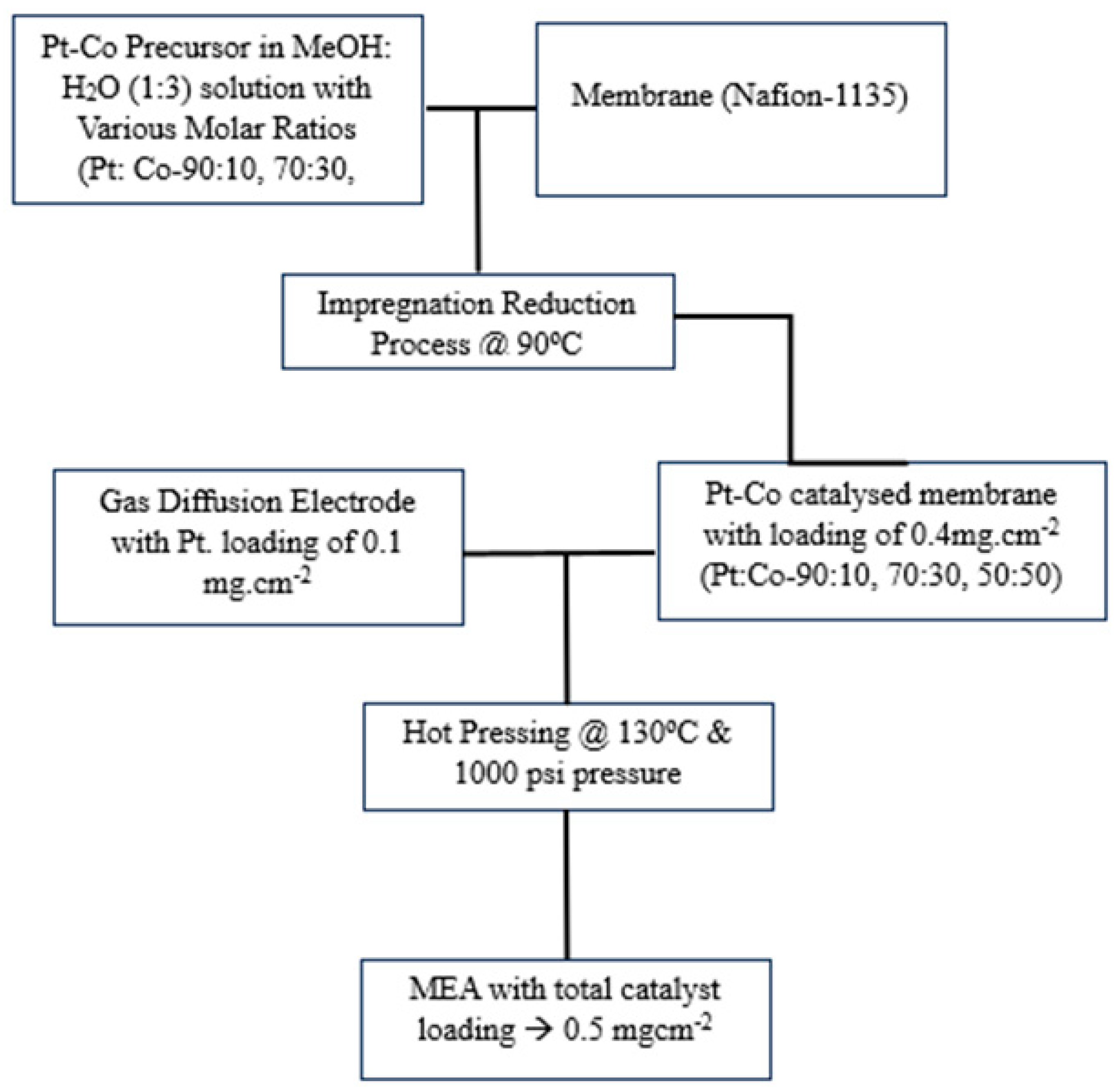
The pretreated membrane was then subjected to drying for 12 h continuously at a temperature of 80 °C in a vacuum oven and then treated using 0.5 M NaCl solution in order to convert the membrane to Na+ form. NEIRP with a modified cell structure, shown in Figure 1, was used to generate three binary alloys of Pt and Co with atomic ratios, viz., Pt:Co ratios of 90:10, 70:30, and 50:50, and nano-catalyzed membranes with constant catalyst loading of 0.4 mgcm−2.
Pt and Co precursors were prepared using Pt(NH3)4Cl2.H2O and CoCl2.6H2O with H2O and HCl, respectively. For the NEIR approach, the membrane’s top surface was treated to an impregnation solution constituting 0.6 mM Pt and Co in a 60 mL MeOH:H2O (1:3) solution for 50 min. Next, the impregnation solution was drained from the cell and reconstituted with a curbing solution containing 10 mM NaBH4 at pH level 13 consistently for 2 h. The solution was stirred at 50 °C at 190 rpm at a 2.5 cm height from the membrane. Eventually, the Pt-Co/PEM was immersed for 1 h in 0.5 M H2SO4 solution and then for 1 h in deionized (DI) water before being dried and weighed. The resulting Pt-Co loading obtained on the membrane was 0.4 mgcm−2. Gravimetric measurements of the initial and final concentrations of the impregnation solution were used to quantify the catalyst deposition on the membrane. For further work, the Pt-Co catalytic membranes were stored in desiccators with a high level of ventilation.

2.4. MEA Fabrication from Pt-Co Nano-Catalyzed Membranes

The Pt-Co-coated Nafion® membrane was hot-pressed across two gas diffusion electrodes (GDEs) containing 0.1 mg cm−2 of 40% Pt/C catalyst on the cathode and similarly with 0.5 mg cm−2 on the anode side. The Pt-Co-catalyzed surface was employed for the cathode side and was hot-pressed for 3 min at 130 °C under a 1000 psi pressure. To develop the GDE, the 40% Pt/C catalyst was treated using a specified amount of DI water and ultra-sonicated for approximately 15 min with the addition of 5 wt. % Nafion® ionomer. The resulting slurry was subsequently sprayed on Teflon-coated micro-porous layered carbon paper with a Sono-tek spray coating apparatus. The process flow diagram for platinum–cobalt-catalyzed membrane fabrication is illustrated in Figure 2.
The GDE was exposed to drying for 10 min at 60 °C and 3 min at 90 °C in an inert environment, and the Pt loading was measured by weight. In addition to the direct loading of Pt-Co upon the surface of the membrane via the impregnation method, an additional layer (0.1 mg cm−2) of 40% Pt/C with a Nafion® ionomer was deposited on the cathode to ensure a high current was carried from the thinner Pt-Co catalyst and to offer a strong contact with the gas diffusion layer (GDL). To ease the comparison analysis, invariably, the net Pt loading on the anode was set as 0.5 mg cm−2, and the topological surface area of all the electrodes were set at 5 cm2.

2.5. Physical Characterization of Pt-Co Nano-Catalyzed Membrane

2.5.1. XRD Analysis

XRD patterns of Ptx-Co100−x (x = 90, 70, and 50) nano-catalyzed membranes are shown in Figure 3.
The peaks observed at 2θ = 40°, 47°, and 68° correlate, respectively, to the (1 1 1), (2 0 0), and (2 2 0) lattice levels of the FCC geometry of Pt, and the amorphous band at approximately 16.5° could be attributed to the crystalline peak of the Nafion® 1135 membrane [30]. Furthermore, it is noteworthy that the peaks corresponding to Co or its oxides were not seen; apparently, the peaks correlating to the samples seem to be shifted slightly towards higher 2θ as the cobalt level increases, confirming alloy formation. Additionally, the shifting of the characteristic peaks indicates the decrease in the inter-atomic distance of Pt upon the substitution with cobalt [31]. Table 1 gives the computed lattice parameter and the Pt–Pt inter-atomic distance.
In the Ptx-Co100−x catalysts, the relatively stable reduction in lattice characteristics with the cobalt ratio (adhering to Vegard’s rule) [32] and the change in the Pt–Pt closest neighbor distance in the alloys compared to pure Pt were claimed to facilitate the rapid reduction in oxygen. Therefore, the decrease in the Pt lattice parameters reported in the as-prepared catalysts could be favorable for oxygen dissociation, and thus, the ultimate fuel cell performance. Table 1 also includes the mean particle size of Pt:Co alloys as determined from the diffraction pattern using Debye–Scherer’s relation [33]. Prominently, due to the identical experimental conditions for sample preparation, the particle size of the alloy samples did not differ with the loadings, and the particle size measured in this study is lesser than the earlier known values [34], possibly due to the lower alloying temperature [35].

2.5.2. High-Resolution Scanning Electron Microscopic Studies (HR-SEM) with EDX

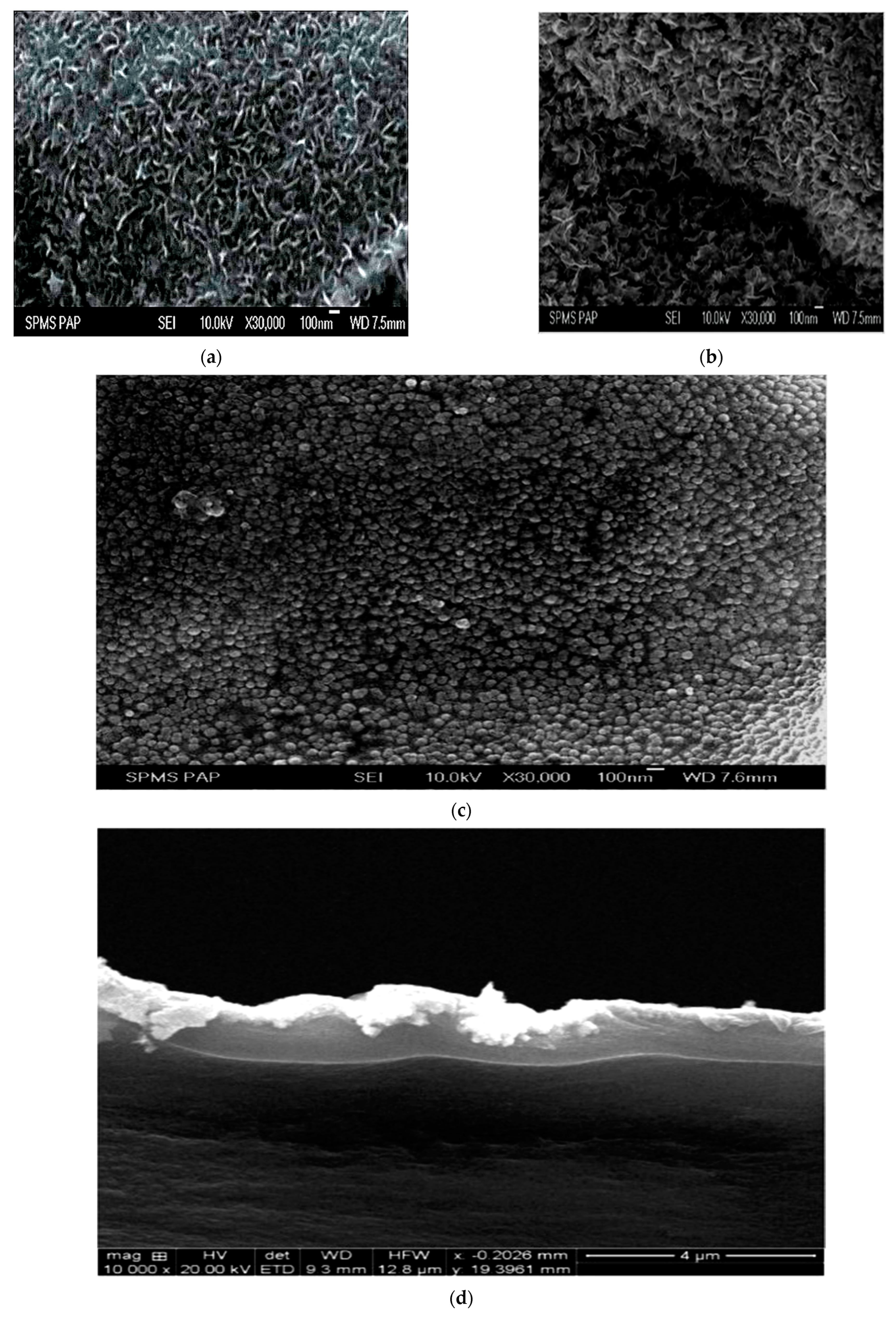
HR-SEM images of the three Ptx-Co100−x nano-alloy-catalyzed membranes are shown in Figure 4a–c. The metal nanoparticles exhibited a good spatial dispersion on the surface of the PEM membrane, and this is a significant factor that is expected to influence the catalyst activity for ORR kinetics [36]. It is also evident from the HR-SEM images that the alloy formation on the membrane surface has an extensively uniform distribution of particles of the Pt-Co alloy with an average size of about 15–25 µm. The authors observed that the average particle size calculated from XRD was smaller than the particle size observed from the HR-SEM images, which is a fact reported by Roxana Muntean et al. [37] in their studies with carbon nanofibers decorated with Pt-Co alloy nanoparticles as catalysts for electrochemical cell applications. Further, the cross-sectional view of the Pt-Co nano-catalyzed membrane with the atomic ratio of 50:50, as a representative sample, is shown in Figure 4d.
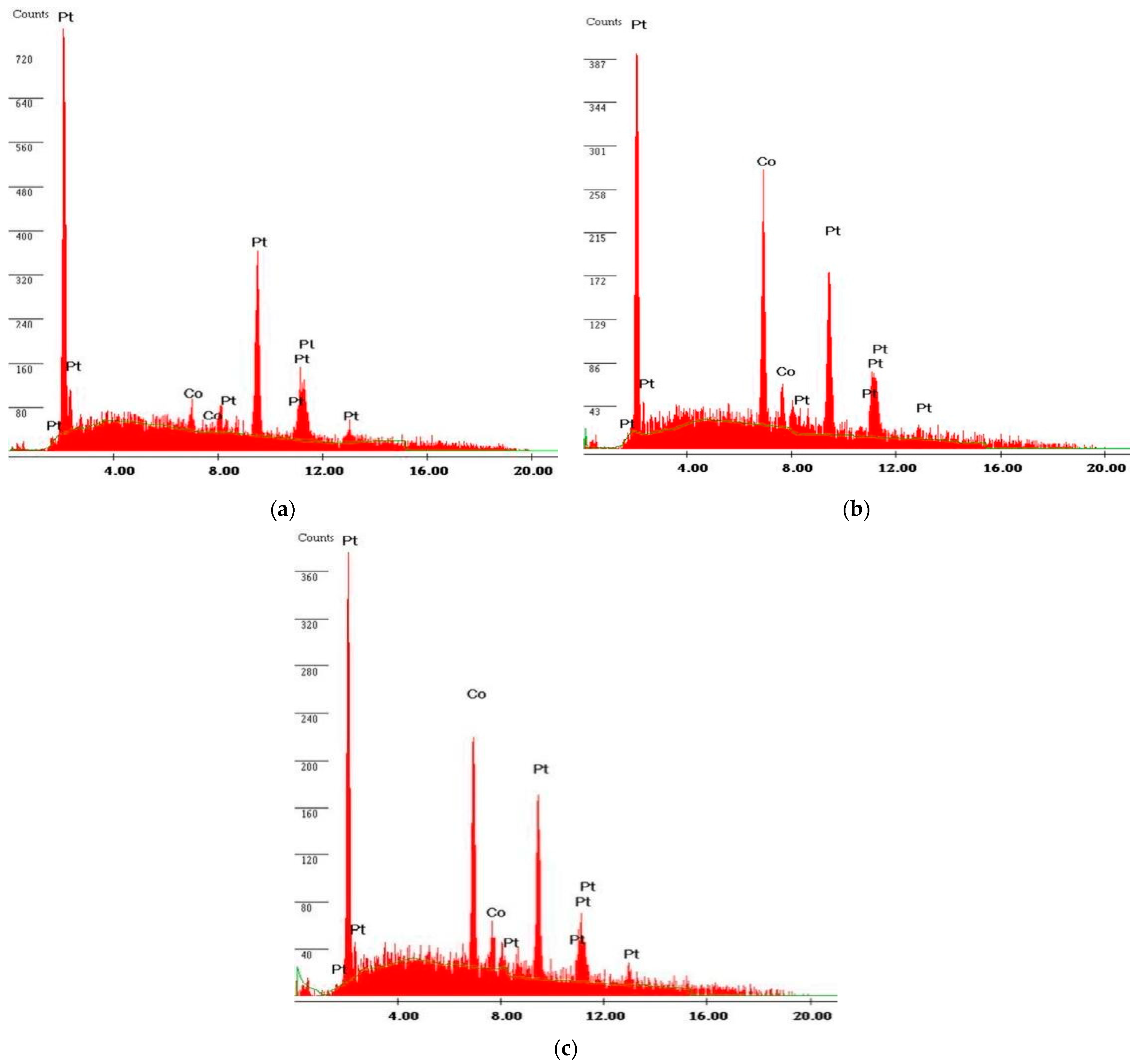
The cross-sectional image shows that the Pt catalyst has a strong bond with the membrane, which lowers the cell’s contact resistance and increases its efficiency. The thickness of the Pt-Co layer on the membrane is ca. 1.5 to 2.0 µm. The EDX spectra of the prepared samples are displayed in Figure 5a–c. The high intense peaks at 2.5 keV and 6.9 keV, respectively, confirm the presence of Pt and Co particles in the three membranes investigated. Invariably, the three membranes displayed peaks corresponding to Pt and Co; however, as expected, the intensity of the peak due to Co was obviously increased as the Co content increased. Accordingly, the elemental composition of the Ptx-Co100−x alloy nano-catalyzed membranes were calculated and are given in Table 2. The obtained atomic ratios are very nearly identical to the nominal value, and furthermore, it is observed that the increase in the Pt content apparently increases the atomic fraction in the deposited layer [38], but an exact correspondence was not observed.

2.6. Electrochemical Characterization of Pt-Co Nano-Catalyzed Membranes

Cyclic Voltammetry Studies

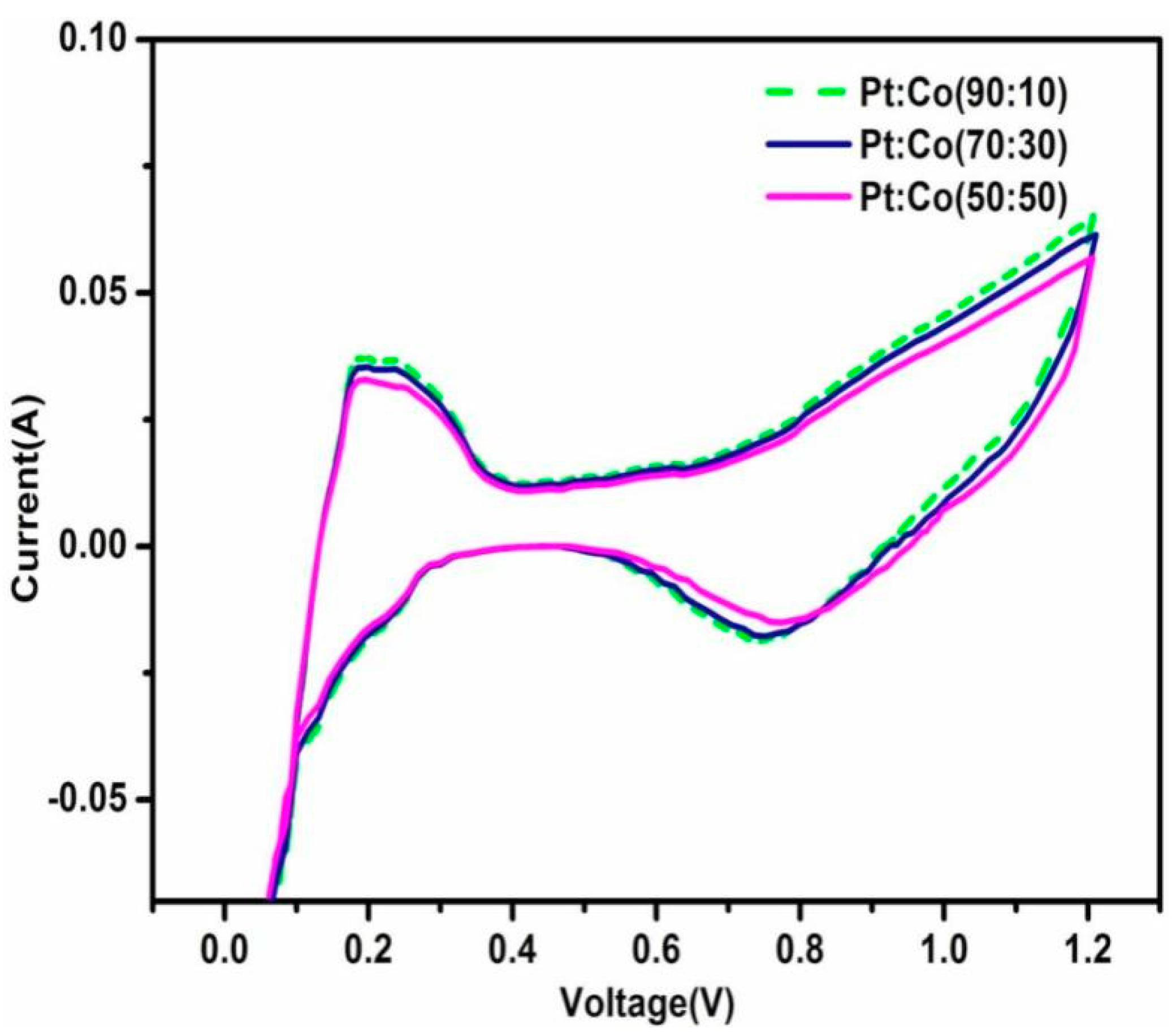
In an effort to define the membrane electrode interface and to obtain a quantifiable steady voltammogram, the electrode was swept through 50 and 1200 mV at a sweep frequency of 50 mV s−1 throughout the first hour. Figure 6 shows the CV of the single cell in which hydrogen and argon were used as the reactant gases. From the CV studies, the electrochemical surface area of the electrocatalyst on each sample was calculated, and it is given in Table 3. It was found that there is a steady decline in the current density of the hydrogen zone in proportion to the increasing concentration of Co in the Pt:Co composition, which modifies the electrochemical active surface area (ECSA). This is in accordance with the study by Sievers et al. [39]. The ECSA of the nano-divided Pt was ascertained via the H adsorption/desorption peaks. All of the platinum and platinum–cobalt alloy catalysts exhibit an identical double-layer characteristic, which signifies that all of the catalysts possess the same levels of resistance to the transport of electrons. In addition, when the amount of Co increased, the onset of oxide production and the peak potential of the oxide both shifted slightly to significantly higher positive potentials (refer Figure 7). This signifies that the oxygenated element (e.g., OH) has a lesser adsorption potential on alloy interfaces compared to the surface of pure Pt particles, i.e., the oxygenated species are simpler to dissolve from the interfaces of alloy particles.
Pt surfaces can be inhibited by the adsorption of OH (or other oxygenated species); therefore, the poor adsorption of oxygenated elements would enhance the interface active surface area for the ORR. This is consistent with the study of Wu et al. [40]. As a consequence, this implies that catalysts made from Pt or Co are stable and do not dissolve under such experimental conditions, as seen by the uniformity of their CV shapes for the oxidation reactions.
Table 3 lists the electrochemical characteristics of each of the produced samples. From the results, it is inferred that the electrochemical properties of the Pt:Co nano-alloy-catalyzed MEA decreased by increasing the Co content. However, the decreasing percentage is comparatively lower than the catalyst prepared using other methods, viz., [41]; this is attributed to the expansion of three-phase boundary of the catalyst layer, as reported by Pethaiah et al. [42]. The electrochemical surface areas (ECSAs) of the MEA fabricated from the Pt-Co nano-catalyzed membrane with different ratios are given in Table 3. The variation in the CSA is directly related to the presence of varying proportions of Pt-Co nano-catalyzed membranes and 40% Pt/C-catalyst-coated GDE in MEA [43].

2.7. Electrochemical Impedance Spectroscopy (EIS)

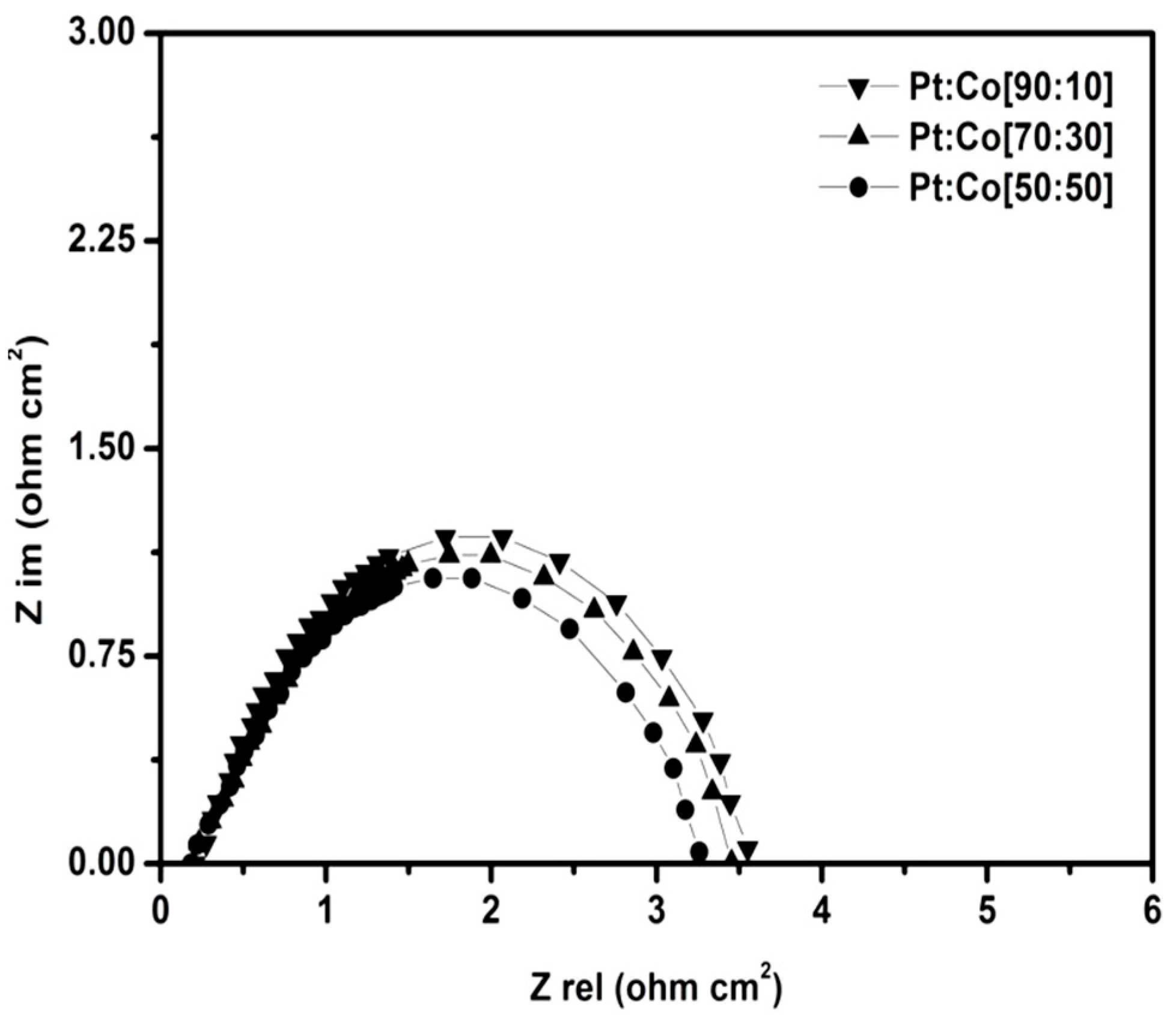
Figure 8 depicts the impedance response of the single cell prepared from the Pt-Co nano-catalyzed membrane with various Pt:Co ratios under H2/O2 at 0.85 V cell potential. Impedance spectra (Nyquist plots) are found to exhibit identical semi-circles, although their diameters dramatically decrease with the increasing Co content [44]. This is due to the reduction in contact resistance at the interface via the Pt–Co network [45]. Since the ORR at cathode kinetically dominates the cell impedance, a smaller impedance curve for the cell generated by the 50:50 ratio of the Pt:Co nano-catalyzed membrane signifies that the ORR of the single cell formed from Pt:Co nano-catalyzed membrane is substantially faster in contrast to that of pure Pt and other ratios. This is consistent with that of the polarization and CV studies.
The impedance parameters obtained from the single cells utilizing the Pt:Co nano-catalyzed membranes with various ratios are presented in Table 4. It is worth mentioning that, under the same testing conditions, the cell employing the Pt:Co (50:50) nano-catalyzed membrane demonstrates a notably lower ohmic resistance, R1, that comprises the internal resistance of the PEMFC (such as the resistance of electrodes, the resistance of conductive plates, and the resistance of proton transfer which are transferring through the PEM) when compared to the other Pt:Co nano-catalyzed membranes. Even though these cells were fabricated and tested under identical conditions, the observed lower R1 in the Pt:Co (50:50) cell may indirectly be attributed to the improved inter-particle contact within the MEA of this specific composition.
Furthermore, the reduced charge transport resistance, R2, suggests a more rapid charge transfer process or enhanced electron kinetics for the Oxygen Reduction Reaction (ORR) at the electrode–electrolyte interface when utilizing Pt:Co nano-catalyzed membranes at the 50:50 ratio [46]. This observation reaffirms that the MEA employing the Pt:Co (50:50) composition possesses a considerably more effective electrochemically active surface area (ECSA) in comparison to the typical MEA employing Pt-Co nano-catalytic membranes, thus proving to be beneficial as electrocatalyst for fuel cell applications.

Polarization Studies

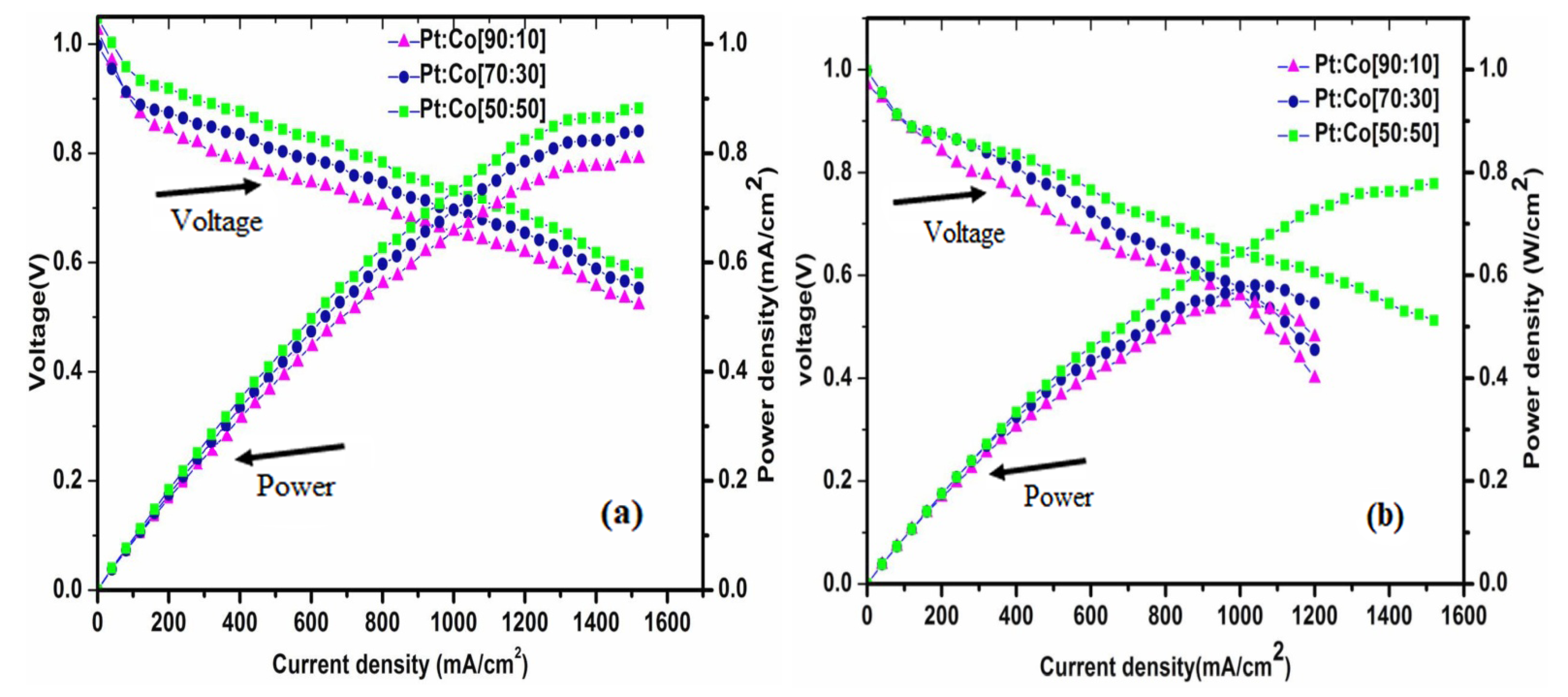
Figure 9 shows the current–voltage characteristics of a single cell made from a Pt:Co nano-catalyzed membrane with variable Pt:Co atomic ratios.
The cells were tested with fully humidified H2/O2 and H2/air reactants at 15 psi pressure and a cell temperature of 80 °C with a constant catalyst loading on both sides of the MEA. According to the results, the Pt:Co atomic ratio variation in the Pt-Co nano-catalyzed membranes exerted a substantial influence on the cell performance not just through the activation phase at the increased cell potential, however, likewise throughout the Ohmic region for a medium cell potential to a low cell potential. Under identical test circumstances, the PEMFC with the 50:50 atomic ratio of Pt:Co outperformed the other Pt:Co atomic ratios. The peak power density was found to be 0.879 Wcm−2 for H2/O2, which is higher than that in the previous study report, which was 0.744 Wcm−2 [47]. The enhanced catalytic activity of the Pt:Co (50:50) alloy catalysts in contrast to Pt and other ratios is because of the minimal Pt-Pt atomic distance [48]. In addition, the higher catalytic activities of Pt alloy catalysts relative to Pt might be a result of other variables, such as variations in the Pt–Pt bond distance, the number of Pt closest neighbors, the electron concentration in the Pt:5d orbital, and surface oxide layers. The catalytic activity may also be influenced by the particle size, as has been described in the literature [35,49,50,51]; however, we do not see any substantial difference in the particle size in relation to the Co concentration. The polarization behaviors of PEMFC made from the Pt-Co nano-catalyzed membrane at a constant voltage of 0.6 V are shown in Table 5.
The single cell made from a Pt:Co nano-catalyzed membrane was investigated for 100 h at a 500 mAcm−2 steady current density to determine its stability, with the same above operating parameters and at an ambient pressure. Steady-state voltage of 0.85 V at 500 mAcm−2 was attained after a gradual rise in voltage over a prolonged period of time, as shown in Figure 10 for the Pt:Co (50:50) nano-catalyzed membrane, as a representative sample.
The findings are in accordance with references [52,53,54,55,56] and hence show that the Pt-Co nano-catalyzed membrane has a high degree of stability. Table 6 provides a comparison on the various related works in the literature along with the present work.
To conclude, the present research bestows the following interesting outcomes.
Firstly, a novel synthesis method, viz., the non-equilibrium impregnation–reduction (NEIR) method, was adopted and has resulted in more efficient Pt-Co alloy electrocatalysts. This method not only enhanced the catalytic activity but also improved the durability of the MEAs. Additionally, the Pt:Co atomic ratio was optimized in a manner that significantly improves the catalyst’s performance in terms of the power output, durability, or cost-effectiveness. These unique attributes make the NEIR approach distinct from the prior similar research.
Secondly, the NEIR method is advantageous as it effectively addresses some of the key challenges observed in previous research, as stated in the earlier sections. By fine-tuning the Pt:Co atomic ratio, the performance of the catalysts and stability were optimized. This improvement directly translates into a higher power output and prolonged MEA lifespan.
Last but not least, the NEIR synthesis method is more efficient and cost-effective, which makes it a practical and economically viable solution for fuel cell applications (PEM-based).

3. Conclusions

The successful development of non-platinum (non-Pt) catalysts plays a crucial role in advancing the commercial viability of Proton Exchange Membrane Fuel Cell (PEMFC) systems. In the context of our investigation, we focused on creating a Pt-Co bimetallic nano-catalyzed membrane using a non-equilibrium impregnation–reduction (NEIR) method. The specific innovation in our study lies in the variation in the Pt and Co atomic ratios within this catalyst, and our findings suggest a remarkable enhancement in the PEMFC performance as the concentration of cobalt (Co) increases.
Through experimentation, it was observed that the Pt-Co-catalyzed membrane demonstrated increasingly promising performance as the Pt:Co atomic ratio approached 50:50. The improvement in performance can be primarily attributed to the alteration in the inter-atomic distance between platinum (Pt) atoms, which results from the inclusion of cobalt. This variation in the electrochemical activity of the catalysts has a beneficial impact on contributing to a higher power output and overall efficiency in the fuel cell. Specifically, peak power density of 0.879 Wcm−2 and 0.727 Wcm−2 are observed when operating the PEMFC respectively with hydrogen/oxygen (H2/O2) fuel and hydrogen/air (H2/air) combination. These results signify substantial progress in both the performance and stability of the Pt–Co nano-catalyzed membrane. Furthermore, this study indicates that this innovation could potentially lead to cost reductions in the production of PEMFC systems. This is a significant advantage as it makes the technology more economically viable and attractive for widespread adoption.
In conclusion, the present investigation demonstrates that the Pt-Co alloy nano-catalyzed membrane exhibits great promise as a candidate for sustainable and efficient power generation in PEMFCs. The improved performance, stability, and potential cost savings make this technology an appealing option for the advancement of PEMFC systems for practical and environmentally sustainable power generation.

Author Contributions

Conceptualization, S.S.P.; Validation, S.S.P. and A.J.; Formal analysis, K.P.; Investigation, A.J. All authors have read and agreed to the published version of the manuscript.

Funding

This research received no external funding.

Data Availability Statement

Data are contained within the article.

Conflicts of Interest

The authors declare no conflict of interest.

References

  1. Athanasaki, G.; Jayakumar, A.; Kannan, A. Gas diffusion layers for PEM fuel cells: Materials, properties and manufacturing—A review. Int. J. Hydrogen Energy 2023, 48, 2294–2313. [Google Scholar] [CrossRef]
  2. Jayakumar, A. An assessment on polymer electrolyte membrane fuel cell stack components. In Applied Physical Chemistry with Multidisciplinary Approaches; Apple Academic Press: Waretown, NJ, USA, 2018; pp. 23–49. [Google Scholar]
  3. Liu, C.; Li, S. Performance Enhancement of Proton Exchange Membrane Fuel Cell through Carbon Nanofibers Grown In Situ on Carbon Paper. Molecules 2023, 28, 2810. [Google Scholar] [CrossRef]
  4. Chen, D.; Pei, P.; Li, Y.; Ren, P.; Meng, Y.; Song, X.; Wu, Z. Proton exchange membrane fuel cell stack consistency: Evaluation methods, influencing factors, membrane electrode assembly parameters and improvement measures. Energy Convers. Manag. 2022, 261, 115651. [Google Scholar] [CrossRef]
  5. Jayakumar, A.; Singamneni, S.; Ramos, M.; Al-Jumaily, A.M.; Pethaiah, S.S. Manufacturing the Gas Diffusion Layer for PEM Fuel Cell Using a Novel 3D Printing Technique and Critical Assessment of the Challenges Encountered. Materials 2017, 10, 796. [Google Scholar] [CrossRef] [PubMed]
  6. Liu, C.; Li, S.; Xing, Y.; Kang, H.; Tan, J.; Guo, W.; Pan, M. Carbon paper coated with Metal-free C-N electrocatalyst for Oxygen Reduction Reaction in Proton Exchange Membrane Fuel Cell. Int. J. Electrochem. Sci. 2018, 13, 7020–7033. [Google Scholar] [CrossRef]
  7. Ren, X.; Wang, Y.; Liu, A.; Zhang, Z.; Lv, Q.; Liu, B. Current progress and performance improvement of Pt/C catalysts for fuel cells. J. Mater. Chem. A 2020, 8, 24284–24306. [Google Scholar] [CrossRef]
  8. Mardle, P.; Thirunavukkarasu, G.; Guan, S.; Chiu, Y.-L.; Du, S. Comparative study of ptni nanowire array electrodes toward oxygen reduction reaction by half-cell measurement and pemfc test. ACS Appl. Mater. Interfaces 2020, 12, 42832–42841. [Google Scholar] [CrossRef] [PubMed]
  9. Tamaki, T.; Kuroki, H.; Ogura, S.; Fuchigami, T.; Kitamoto, Y.; Yamaguchi, T. Connected nanoparticle catalysts possessing a porous, hollow capsule structure as carbon-free electrocatalysts for oxygen reduction in polymer electrolyte fuel cells. Energy Environ. Sci. 2015, 8, 3545–3549. [Google Scholar] [CrossRef]
  10. Liu, D.; Li, X.; Chen, S.; Yan, H.; Wang, C.; Wu, C.; Haleem, Y.A.; Duan, S.; Lu, J.; Ge, B.; et al. Atomically dispersed platinum sup-ported on curved carbon supports for efficient electrocatalytic hydrogen evolution. Nat. Energy 2019, 4, 512–518. [Google Scholar] [CrossRef]
  11. Hou, J.; Yang, M.; Ke, C.; Wei, G.; Priest, C.; Qiao, Z.; Wu, G.; Zhang, J. Platinum-group-metal catalysts for proton exchange membrane fuel cells: From catalyst design to electrode structure optimization. EnergyChem 2020, 2, 100023. [Google Scholar] [CrossRef]
  12. Wang, X.X.; Swihart, M.T.; Wu, G. Achievements, challenges and perspectives on cathode catalysts in proton ex-change membrane fuel cells for transportation. Nat. Catal. 2019, 2, 578–589. [Google Scholar] [CrossRef]
  13. Wu, D.; Shen, X.; Pan, Y.; Yao, L.; Peng, Z. Platinum Alloy Catalysts for Oxygen Reduction Reaction: Advances, Challenges and Perspectives. Chemnanomat 2020, 6, 32–41. [Google Scholar] [CrossRef]
  14. Lori, O.; Elbaz, L. Recent Advances in Synthesis and Utilization of Ultra-low Loading of Precious Metal-based Catalysts for Fuel Cells. ChemCatChem 2020, 12, 3434–3446. [Google Scholar] [CrossRef]
  15. Lim, B.H.; Majlan, E.H.; Tajuddin, A.; Husaini, T.; Daud, W.R.W.; Radzuan, N.A.M.; Haque, A. Comparison of catalyst-coated membranes and catalyst-coated substrate for PEMFC membrane electrode assembly: A review. Chin. J. Chem. Eng. 2021, 33, 1–16. [Google Scholar] [CrossRef]
  16. Yarlagadda, V.; McKinney, S.E.; Keary, C.L.; Thompson, L.; Zulevi, B.; Kongkanand, A. Preparation of PEMFC Electrodes from Milligram-Amounts of Catalyst Powder. J. Electrochem. Soc. 2017, 164, F845–F849. [Google Scholar] [CrossRef]
  17. Ungan, H.; Yurtcan, A.B. PEMFC catalyst layer modification with the addition of different amounts of PDMS polymer in order to improve water management. Int. J. Energy Res. 2019, 43, 5946–5958. [Google Scholar] [CrossRef]
  18. Arenas, L.F.; Hadjigeorgiou, G.; Jones, S.; Van Dijk, N.; Hodgson, D.; Cruden, A.; de León, C.P. Effect of airbrush type on sprayed platinum and platinum-cobalt catalyst inks: Benchmarking as PEMFC and performance in an electrochemical hydrogen pump. Int. J. Hydrogen Energy 2020, 45, 27392–27403. [Google Scholar] [CrossRef]
  19. Du, S.; Guan, S.; Mehrazi, S.; Zhou, F.; Pan, M.; Zhang, R.; Chuang, P.-Y.A.; Sui, P.-C. Effect of Dispersion Method and Catalyst on the Crack Morphology and Performance of Catalyst Layer of PEMFC. J. Electrochem. Soc. 2021, 168, 114506. [Google Scholar] [CrossRef]
  20. Yang, D.; Guo, Y.; Tang, H.; Wang, Y.; Yang, D.; Ming, P.; Zhang, C.; Li, B.; Zhu, S. Influence of the dispersion state of ionomer on the dispersion of catalyst ink and the construction of catalyst layer. Int. J. Hydrogen Energy 2021, 46, 33300–33313. [Google Scholar] [CrossRef]
  21. Melo, L.; Benavides, R.; Martínez, G.; Morales-Acosta, D.; Paula, M.; Da Silva, L. Sulfonated polystyrene-co-acrylic acid membranes modified by transmembrane reduction of platinum. Int. J. Hydrogen Energy 2017, 42, 30407–30416. [Google Scholar] [CrossRef]
  22. Sethu, S.P.; Gangadharan, S.; Chan, S.H.; Stimming, U. Development of a novel cost effective methanol electrolyzer stack with Pt-catalyzed membrane. J. Power Sources 2011, 254, 161–167. [Google Scholar] [CrossRef]
  23. Alia, S.M.; Jensen, K.O.; Pivovar, B.S.; Yan, Y. Platinum-Coated Palladium Nanotubes as Oxygen Reduction Reaction Electrocatalysts. ACS Catal. 2012, 2, 858–863. [Google Scholar] [CrossRef]
  24. Tokarz, W.; Lota, G.; Frackowiak, E.; Czerwiński, A.; Piela, P. Fuel cell testing of Pt–Ru catalysts supported on differently prepared and pretreated carbon nanotubes. Electrochim. Acta 2013, 98, 94–103. [Google Scholar] [CrossRef]
  25. Kwon, S.; Ham, D.J.; Lee, S.G. Enhanced H2 dissociative phenomena of Pt–Ir electrocatalysts for PEMFCs: An integrated experimental and theoretical study. RSC Adv. 2015, 5, 54941–54946. [Google Scholar] [CrossRef]
  26. Garcia-Cardona, J.; Sirés, I.; Alcaide, F.; Brillas, E.; Centellas, F.; Cabot, P.L. Electrochemical performance of carbon-supported Pt(Cu) electrocatalysts for low-temperature fuel cells. Int. J. Hydrogen Energy 2020, 45, 20582–20593. [Google Scholar] [CrossRef]
  27. Wang, Q.; Mi, B.; Zhou, J.; Qin, Z.; Chen, Z.; Wang, H. Hollow-Structure Pt-Ni Nanoparticle Electrocatalysts for Oxygen Reduction Reaction. Molecules 2022, 27, 2524. [Google Scholar] [CrossRef] [PubMed]
  28. Sakthivel, M.; Radev, I.; Peinecke, V.; Drillet, J.-F. Highly active and stable pt3cr/c alloy catalyst in h2-pemfc. J. Electrochem. Soc. 2015, 162, F901. [Google Scholar] [CrossRef]
  29. Emery, M.; Frey, M.; Guerra, M.; Haugen, G.; Hintzer, K.; Lochhaas, K.H.; Pham, P.; Pierpont, D.; Schaberg, M.; Thaler, A.; et al. The Development of New Membranes for Proton Exchange Membrane Fuel Cells. ECS Trans. 2007, 11, 3–14. [Google Scholar] [CrossRef]
  30. Bragaru, A.; Vasile, E.; Danila, M.; Kusko, M.; Simion, M.; Iordanescu, A.; Pascu, R.; Craciunoiu, F.; Leca, M. Microstructural studies of platinum nanoparticles dispersed in nafion membrane. Optoelectron. Adv. Mater.-Rapid Commun. 2014, 5, 161–167. [Google Scholar]
  31. Baronia, R.; Goel, J.; Tiwari, S.; Singh, P.; Singh, D.; Singh, S.P.; Singhal, S.K. Efficient electro-oxidation of methanol using PtCo nanocatalysts supported reduced graphene oxide matrix as anode for DMFC. Int. J. Hydrogen Energy 2017, 42, 10238–10247. [Google Scholar] [CrossRef]
  32. Wen, Y.-H.; Huang, R. Effect of Chemical Ordering on Thermal Stability of Pt–Co Nanoparticles. J. Phys. Chem. C 2019, 123, 12007–12014. [Google Scholar] [CrossRef]
  33. Hargreaves, J.S.J. Some considerations related to the use of the Scherrer equation in powder X-ray diffraction as applied to heterogeneous catalysts. Catal. Struct. React. 2016, 2, 33–37. [Google Scholar] [CrossRef]
  34. Woo, J.-Y.; Lee, K.-M.; Jee, B.-C.; Ryu, C.-H.; Yoon, C.-H.; Chung, J.-H.; Kim, Y.-R.; Moon, S.-B.; Kang, A.-S. Electrocatalytic char-acteristics of Pt–Ru–Co and Pt–Ru–Ni based on covalently cross-linked sulfonated poly (ether ketone)/heteropolyacids com-posite membranes for water electrolysis. J. Ind. Eng. Chem. 2010, 16, 688–697. [Google Scholar] [CrossRef]
  35. Antolini, E. Structural parameters of supported fuel cell catalysts: The effect of particle size, inter-particle distance and metal loading on catalytic activity and fuel cell performance. Appl. Catal. B Environ. 2016, 181, 298–313. [Google Scholar] [CrossRef]
  36. Xu, J.; Aili, D.; Li, Q.; Christensen, E.; Jensen, J.O.; Zhang, W.; Hansen, M.K.; Liu, G.; Wang, X.; Bjerrum, N.J. Oxygen evolution catalysts on supports with a 3-D ordered array structure and intrinsic proton conductivity for proton exchange membrane steam electrolysis. Energy Environ. Sci. 2014, 7, 820–830. [Google Scholar] [CrossRef]
  37. Muntean, R.; Pascal, D.-T.; Mărginean, G.; Vaszilcsin, N. Carbon Nanofibers Decorated with Pt-Co Alloy Nanoparticles as Catalysts for Electrochemical Cell Applications. I. Synthesis and Structural Characterization. Int. J. Electrochem. Sci. 2017, 12, 4597–4609. [Google Scholar] [CrossRef]
  38. Zhang, J.; Chen, W.; Ge, H.; Chen, C.; Yan, W.; Gao, Z.; Gan, J.; Zhang, B.; Duan, X.; Qin, Y. Synergistic effects in atom-ic-layer-deposited ptcox/cnts catalysts enhancing hydrolytic dehydrogenation of ammonia borane. Appl. Catal. B Environ. 2018, 235, 256–263. [Google Scholar] [CrossRef]
  39. Sievers, G.W.; Jensen, A.W.; Quinson, J.; Zana, A.; Bizzotto, F.; Oezaslan, M.; Dworzak, A.; Kirkensgaard, J.J.K.; Smitshuysen, T.E.L.; Kadkhodazadeh, S.; et al. Self-supported Pt–CoO networks combining high specific activity with high surface area for oxygen reduction. Nat. Mater. 2020, 20, 208–213. [Google Scholar] [CrossRef]
  40. Wu, H.; Wexler, D.; Liu, H.; Savadogo, O.; Ahn, J.; Wang, G. Pt1−xCox nanoparticles as cathode catalyst for proton exchange membrane fuel cells with enhanced catalytic activity. Mater. Chem. Phys. 2010, 124, 841–844. [Google Scholar] [CrossRef]
  41. Rao, C.V.; Parrondo, J.; Ghatty, S.L.; Rambabu, B. High temperature polymer electrolyte membrane fuel cell performance of PtxCoy/C cathodes. J. Power Sources 2010, 195, 3425–3430. [Google Scholar] [CrossRef]
  42. Pethaiah, S.S.; Kalaignan, G.P.; Sasikumar, G.; Ulaganathan, M. Evaluation of platinum catalyzed MEAs for PEM fuel cell applications. Solid State Ion. 2011, 190, 88–92. [Google Scholar] [CrossRef]
  43. Shroti, N.; Daletou, M.K. The Pt–Co alloying effect on the performance and stability of high temperature PEMFC cathodes. Int. J. Hydrogen Energy 2022, 47, 16235–16248. [Google Scholar] [CrossRef]
  44. Tang, Z.; Poh, C.K.; Chin, K.C.; Chua, D.H.C.; Lin, J.; Wee, A.T.S. Cobalt coated electrodes for high efficiency PEM fuel cells by plasma sputtering deposition. J. Appl. Electrochem. 2009, 39, 1821–1826. [Google Scholar] [CrossRef]
  45. Giubileo, F.; Di Bartolomeo, A. The role of contact resistance in graphene field-effect devices. Prog. Surf. Sci. 2017, 92, 143–175. [Google Scholar] [CrossRef]
  46. Sharma, S.; Pollet, B.G. Support materials for PEMFC and DMFC electrocatalysts—A review. J. Power Sources 2012, 208, 96–119. [Google Scholar] [CrossRef]
  47. Sundar Pethaiah, S.; Paruthimal Kalaignan, G.; Sasikumar, G.; Ulaganathan, M.; Swaminathan, V. Development of nano-catalyzed membrane for PEM fuel cell applications. J. Solid State Electrochem. 2013, 17, 2917–2925. [Google Scholar] [CrossRef]
  48. Liu, Z.; Yin, Y.; Yang, D.; Zhang, C.; Ming, P.; Li, B.; Yang, S. Efficient synthesis of Pt–Co nanowires as cathode catalysts for proton exchange membrane fuel cells. RSC Adv. 2020, 10, 6287–6296. [Google Scholar] [CrossRef]
  49. Su, L.; Jia, W.; Li, C.-M.; Lei, Y. Mechanisms for Enhanced Performance of Platinum-Based Electrocatalysts in Proton Exchange Membrane Fuel Cells. ChemSusChem 2014, 7, 361–378. [Google Scholar] [CrossRef]
  50. Scofield, M.E.; Liu, H.; Wong, S.S. A concise guide to sustainable PEMFCs: Recent advances in improving both oxygen reduction catalysts and proton exchange membranes. Chem. Soc. Rev. 2015, 44, 5836–5860. [Google Scholar] [CrossRef]
  51. Lin, R.; Cai, X.; Zeng, H.; Yu, Z. Stability of High-Performance Pt-Based Catalysts for Oxygen Reduction Reactions. Adv. Mater. 2018, 30, e1705332. [Google Scholar] [CrossRef]
  52. Cui, Y.; Wu, Y.; Wang, Z.; Yao, X.; Wei, Y.; Kang, Y.; Du, H.; Li, J.; Gan, L. Mitigating Metal Dissolution and Redeposition of Pt-Co Catalysts in PEM Fuel Cells: Impacts of Structural Ordering and Particle Size. J. Electrochem. Soc. 2020, 167, 064520. [Google Scholar] [CrossRef]
  53. Jung, W.S.; Popov, B.N. New method to synthesize highly active and durable chemically ordered fct-PtCo cathode catalyst for PEMFCs. ACS Appl. Mater. Interfaces 2017, 9, 23679–23686. [Google Scholar] [CrossRef] [PubMed]
  54. Wang, X.X.; Hwang, S.; Pan, Y.-T.; Chen, K.; He, Y.; Karakalos, S.G.; Zhang, H.; Spendelow, J.S.; Su, D.; Wu, G. Ordered Pt3Co Intermetallic Nanoparticles Derived from Metal–Organic Frameworks for Oxygen Reduction. Nano Lett. 2018, 18, 4163–4171. [Google Scholar] [CrossRef] [PubMed]
  55. Wang, C.; Spendelow, J.S. Recent developments in Pt–Co catalysts for proton-exchange membrane fuel cells. Curr. Opin. Electrochem. 2021, 28, 100715. [Google Scholar] [CrossRef]
  56. Yang, B.; Yu, X.; Hou, J.; Xiang, Z. Secondary reduction strategy synthesis of Pt–Co nanoparticle catalysts towards boosting the activity of proton exchange membrane fuel cells. Particuology 2023, 79, 18–26. [Google Scholar] [CrossRef]
  57. Pethaiah, S.S.; Kalaignan, G.P.; Ulaganathan, M.; Arunkumar, J. Preparation of durable nanocatalyzed MEA for PEM fuel cell applications. Ionics 2011, 17, 361–366. [Google Scholar] [CrossRef]
  58. Rajalakshmi, N.; Ryu, H.; Dhathathreyan, K. Platinum catalysed membranes for proton exchange membrane fuel cells—Higher performance. Chem. Eng. J. 2004, 102, 241–247. [Google Scholar] [CrossRef]
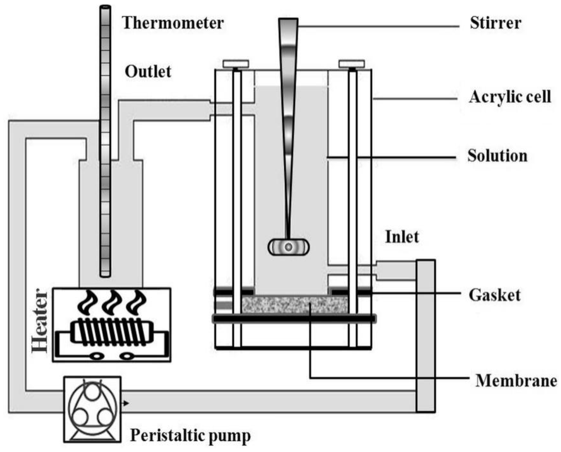
Figure 1. Schematic diagram for non-equilibrium impregnation–reduction method for fuel cell.
Energies 16 07713 g001
Figure 2. Process flow diagram for Pt-Co-catalyzed membrane.
Energies 16 07713 g002
Figure 3. XRD analysis pattern of prepared Pt-Co nano-catalyzed membranes.
Energies 16 07713 g003
Figure 4. HR-SEM images of (a) 90:10; (b) 70:30; (c) 50:50 at % of Pt-Co in the nano-catalyzed membranes. (d) Cross-sectional view of Pt-Co (50:50) nano-catalyzed membrane.
Energies 16 07713 g004
Figure 5. EDX spectrum of (a) 90:10; (b) 70:30; (c) 50:50 at % of Pt-Co in the nano-catalyzed membranes. (The unit of abscissa is keV).
Energies 16 07713 g005
Figure 6. Cyclic voltammogram of MEA made from Pt-Co nano-catalyzed membrane with various atomic ratios.
Energies 16 07713 g006
Figure 7. Positively shifted reduction peak potential of Pt-Co nano-catalyzed membrane with various atomic ratios.
Energies 16 07713 g007
Figure 8. Impedance plot (Nyquist) of the MEA made from Pt-Co nano-catalyzed membrane with various atomic ratios. Inset: equivalent circuit; R1 is ohmic resistance, R2 is charge transfer resistance, and Cdl is double-layer capacitance.
Energies 16 07713 g008
Figure 9. Polarization curves of PEMFC made from Pt-Co nano-catalyzed membranes for (a) H2/O2 and (b) H2/Air.
Energies 16 07713 g009
Figure 10. Durability study of Pt:Co (50:50) nano-catalyzed membrane at 500 mAcm−2.
Energies 16 07713 g010
Table 1. Physical parameters of the Pt:Co nano-catalyzed membranes obtained from XRD.
SamplesLattice Parameter (μm)Pt-Pt Inter-Atomic Distance (μm)Particle Size (μm)
Pt-Co (90:10)0.39480.2279775.1
Pt-Co (70:30)0.39140.2259905.1
Pt-Co (50:50)0.38920.2247525.3
Table 2. The elemental composition of Pt-Co present in membrane analyzed via EDX.
Pt:Co in Solution at %Pt:Co in Membrane at %
90:1093:7
70:3072:28
50:5051:49
Table 3. Electrochemical properties of all MEAs made from Pt-Co nano-catalyzed membranes.
Pt:Co Atomic RatiosECSA (cm2)RFEAS (m2g−1)ECSA (m2g−1)Catalyst Utilization (%)
90:1011502304662.6773.40
70:3011002204462.6770.21
50:5010502104261.8167.95
Table 4. Fitted impedance parameters of the single cells made of Pt-Co nano-catalyzed membrane with various atomic ratios.
Pt:Co Atomic Ratio %R1R2
90:100.223.56
70:300.193.46
50:500.183.26
Table 5. Polarization behaviors of PEMFC made from Pt-Co nano-catalyzed membrane at constant voltage of 0.6 V.
Pt:Co Atomic RatiosCurrent Density (mAcm−2)Power Density (Wcm−2)
H2/O2H2/AirH2/O2H2/Air
90:1012808800.760.52
70:3013609200.820.55
50:50148012000.880.73
Table 6. Performance assessment on the various related works in the literature vs. the present work.
S. No.Composition of the AlloyFuel/OxidantPeak Power Density @ 0.6 V (Wcm−2)Ref. No.
1Pt.H2/O20.72[42]
2Pt/CH2/O20.615[57]
3Pt.H2/O20.6 [58]
4Pt-CoH2/O20.88Present Work
Disclaimer/Publisher’s Note: The statements, opinions and data contained in all publications are solely those of the individual author(s) and contributor(s) and not of MDPI and/or the editor(s). MDPI and/or the editor(s) disclaim responsibility for any injury to people or property resulting from any ideas, methods, instructions or products referred to in the content.