Abstract
This paper proposes a hybrid power supply system for commercial drones. The proposed hybrid power supply system consists of a lithium polymer battery, a supercapacitor, and a power converter for charging the supercapacitor. In the proposed system, the supercapacitor is pre-charged with a lithium polymer battery through a power converter, and the supercapacitor first supplies the power required for the drone’s initial startup and lift-up. Afterward, in the section where the power consumption of the drone is low, the battery and the supercapacitor supply power together, minimizing the stress on the battery. To verify the proposed hybrid power supply system, a computer simulation was conducted, the actual hardware was fabricated, and experiments were performed.
1. Introduction
Recently, drones, also referred to as unmanned aerial vehicles (UAVs), have become increasingly popular and are widely used in various industries and application fields. These drones were initially developed for military purposes, but as their use is gradually recognized in various fields, they are applied to fields such as agriculture, construction, lifesaving, and logistics delivery. These types of drones that are applied in different fields to replace tasks that are difficult for humans to perform are called industrial drones, and research is being actively conducted to develop industrial drones equipped with various functions [1,2,3,4].
Lithium polymer (Li-Po) batteries are commonly used as power sources for industrial drones. Li-Po batteries are rechargeable batteries that use solid polymer electrolytes instead of liquid or gel electrolytes found in conventional lithium-ion (Li-ion) batteries [5,6]. Because of their high energy density, Li-Po batteries can store significant amounts of energy in relatively small and lightweight packages, and because they use lightweight polymer materials, they are lighter than other rechargeable batteries. They can provide a large amount of power quickly compared to other rechargeable batteries. For this reason, Li-Po batteries are used in most UAVs [7,8,9,10]. However, since they are very sensitive to overcharge, overdischarge, and high temperature, the risk of thermal runaway is high, and in extreme cases, a fire or explosion may occur. In addition, the capacity gradually decreases over time, and the output power decreases because the internal resistance increases at a low temperature [11,12]. Due to the advantages described above, Li-Po batteries are mainly used for drones that require a lot of power during flight and must be light in weight. However, due to the nature of drones that require excessive power during flight, the disadvantages of Li-Po batteries are becoming more prominent.
The most important thing in the operation of industrial drones is the flight time of the drone, and the flight time has a close relationship with the capacity of the battery mounted on the drone. In general, increasing capacity by connecting batteries in parallel increases flight time, but it is difficult to add batteries because drones consume different power depending on the take-off weight, and space for batteries is limited [13,14]. In addition, the power consumption of drones is very high due to high-performance BLDC motors for generating thrust. In particular, power consumption can be further increased due to initial startup, upward startup, and logistics loading [15,16]. This feature can overdischarge the Li-Po battery, which can shorten the flight time and cause thermal runaway of the Li-Po battery. A supercapacitor is proposed as a solution to this problem. Table 1 compares lithium secondary batteries and supercapacitors. Supercapacitors have higher power density, longer lifespan, and wider operating temperature range, and they can be rapidly charged and discharged compared to batteries [17,18,19].

Table 1.
Comparison of lithium batteries and supercapacitors.
If a supercapacitor is added to a drone that uses a Li-Po battery alone, the stress applied to the Li-Po battery can be reduced, which can be a way to minimize the disadvantages of the drone caused by the Li-Po battery described above. Therefore, studies on these systems are increasing [20,21]. A power supply system that combines a supercapacitor to compensate for the disadvantages of a lithium battery is called a hybrid power supply system. When this system is applied to a place that requires a large amount of power for a short moment, such as during the initial startup and ascent of a drone, the supercapacitor can assist the discharge C-rate that the Li-Po battery cannot handle. Therefore, a more stable operation than before can be made possible [22,23,24,25,26,27].
Studies on battery stress reduction and lifespan have been conducted on different hybrid power supply systems in [28,29,30,31,32,33], and the results have concluded that the presence of supercapacitors actually helps reduce battery stress and extend battery life.
The innovation or contribution of this research is to further increase the efficiency of battery stress reduction by the supercapacitor by adding a power conversion device to the existing hybrid system in which the battery and supercapacitor are simply connected in parallel.
In this paper, we propose a hybrid power supply system combining a Li-Po battery and a supercapacitor and its operation method to overcome the above-mentioned disadvantages in the operation of industrial drones. In the proposed hybrid power supply system, the voltage of the supercapacitor is raised higher than that of the Li-Po battery through a power converter, and then the supercapacitor first supplies power alone when power is needed for the drone. As the supercapacitor is discharged, when the voltage of the supercapacitor becomes the same as the voltage of the Li-Po battery, the Li-Po battery also starts to discharge. The power converter for charging a supercapacitor must perform a charging operation both in a section where the voltage of the supercapacitor is lower than and higher than the voltage of the Li-Po battery. Therefore, an H-Bridge buck–boost converter (HBBBC) topology capable of both step-up and step-down was applied. In the proposed system, the step-down mode is transferred from the step-down mode to the step-up mode while the converter is charging the supercapacitor. Since the main switch used in the HBBBC differs depending on the operating mode, an accident may occur if there is no proper transfer technique. Therefore, in this paper, a mode transfer technique to solve this problem is also proposed.
The main contributions of this paper are listed below:
- (1)
- The hybrid power supply system is effective in reducing the risk of various explosions and fire accidents that may occur in fields where lithium batteries are used.
- (2)
- Since the step-down and step-up operation of the converter is possible with a single controller through the mode transfer method, there is no need to design a controller for each mode of the converter.
- (3)
- The efficient power management of Li-Po batteries is possible because the supercapacitor supplies power preferentially during flight sections where UAVs consume excessive power.
The validity of the hybrid power supply system proposed in this paper, its operating technique, and the mode transfer method of the power converter for charging the supercapacitor were verified through simulation and experiment.
2. Hybrid Power Supply System for Industrial Drones
Figure 1 shows the overall configuration of the hybrid power supply system proposed in this paper, which combines a lithium battery and a supercapacitor. The proposed system consists of a Li-Po battery, a supercapacitor, an HBBBC, and a protection circuit that connects a relay and a diode in series.
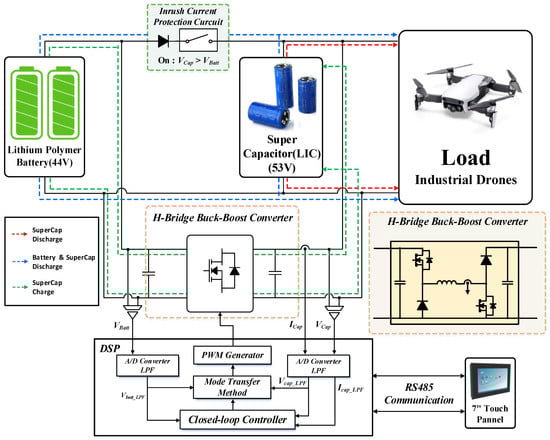
Figure 1.
Configuration of hybrid power supply system using lithium battery and supercapacitor.
The input of the system is 44.4 V by configuring two 22.2 V (3.7 V × 6 cells) Li-Po batteries in series, and the supercapacitor used as output is a lithium-ion capacitor (LIC) module. One cell is 3.8 V, 3200 F, but 14 cells are connected in series to have a specification of 53 V, 228 F. Supercapacitors are largely divided into LICs and electric double-layer capacitors (EDLCs) that combine the advantages of batteries and capacitors. LICs can store a large amount of energy similar to batteries but are characterized by being able to charge and discharge faster than capacitors. In addition, because of the long cycle life, they can undergo many charge–discharge cycles without performance degradation, so their efficiency is higher than that of EDLCs. However, since the voltage level per cell is fixed like a battery, care must be taken for complete discharge. For the above reason, this paper applied the LIC module.
2.1. Operation Method of the Proposed Hybrid Power Supply System
The hybrid power supply system proposed in this paper is operated in three operating modes according to the power consumption patterns that appear when industrial drones fly. Figure 2 is a graph showing power consumption by time and the flight altitude of industrial drones. The section with the highest power consumption of the drone is the section where the drone starts ascending at the same time as the initial maneuver on the ground. In addition, it can be confirmed through Figure 2 that power consumption is high even in the section where the flight altitude rises.
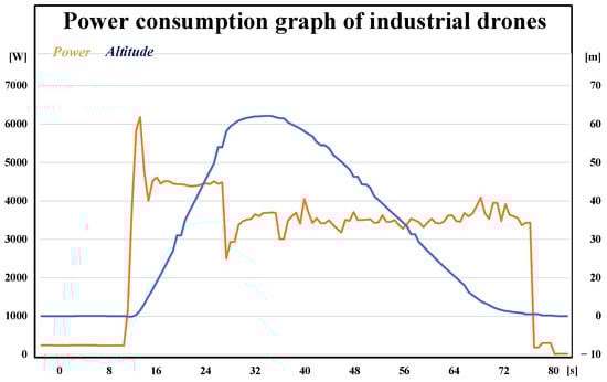
Figure 2.
Power consumption graph of industrial drones.
If the Li-Po battery alone supplies the power required for initial startup, overdischarge proceeds in a short period of time, which can put great stress on the Li-Po battery and drastically reduce the total flight time of the drone. This means that if the supercapacitor supplies the amount of power required during the initial startup and during the rising period, the stress applied to the Li-Po battery can be minimized.
The operating mode of the hybrid power supply system proposed in this paper is as follows.
Mode 1: supercapacitor charging mode;
Mode 2: supercapacitor discharging mode;
Mode 3: supercapacitor and Li-Po battery discharging mode.
Figure 3 shows Mode 1: supercapacitor charging mode. Mode 1 is a mode in which the LIC is charged with the Li-Po battery using the HBBBC before the drone starts flying. Due to the circuit structure, the voltage of the LIC must be higher than the voltage of the Li-Po battery in order for the LIC to supply power alone when the drone initially starts. The LIC has a voltage of 2.8 V per cell when discharged and 3.8 V when fully charged, and the 14 series LIC module applied to the proposed system needs to be charged from 39.2 V to 53 V. Since the voltage of the Li-Po battery for capacitor charging is 44 V, the HBBBC operates in the buck mode when the voltage of the capacitor is lower than that of the lithium polymer battery. In the section where the capacitor voltage is equal to or higher than that of the Li-Po battery, it operates in the boost mode. In this mode, the relay between the Li-Po and the LIC is turned off, so the LIC can only be charged through the HBBBC.
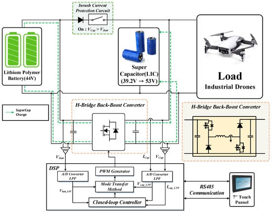
Figure 3.
Mode 1: supercapacitor charging mode.
Figure 4 shows Mode 2: supercapacitor discharge mode. When the drone starts flying after the LIC module is fully charged through Mode 1, the LIC module alone supplies power to the drone. As can be seen from the drone power consumption graph in Figure 2, the drone consumes a lot of power during initial startup and elevation, and then the power consumption gradually decreases. Therefore, in this section, the LIC must supply power to the drone alone to minimize stress and excessive power consumption on the Li-Po battery. Since the voltage of the LIC is higher than the voltage of the Li-Po battery, the relay is turned on, but power is supplied to the drone only from the LIC due to a potential difference.
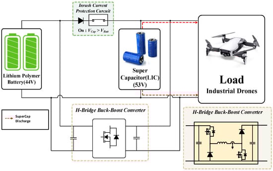
Figure 4.
Mode 2: supercapacitor discharging mode.
Figure 5 shows Mode 3: supercapacitor and Li-Po battery simultaneous discharge mode. In Mode 3, the LIC alone supplies power to the drone in Mode 2, and it starts from the moment the voltage of the LIC and the voltage of the Li-Po battery become the same. From this point on, the Li-Po battery and LIC are discharged together to supply power to the drone. Since the Li-Po battery starts to discharge in the period when the power consumption of the drone is low, and the LIC is also discharged together, it is possible to minimize the stress applied to the Li-Po battery.
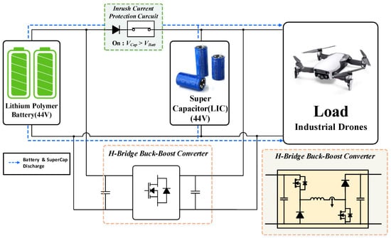
Figure 5.
Mode 3: supercapacitor and Li-Po battery discharging mode.
2.2. H-Bridge Buck–Boost Converter (HBBBC)
As described in “Mode 1: supercapacitor charging mode” of Section 2.1, the HBBBC must operate in the buck mode and boost mode to charge the LIC. Figure 6 shows the HBBBC topology. The HBBBC is also called a non-inverting buck–boost converter because the output voltage is not inverted, unlike a general buck–boost converter. Depending on the switch that operates as the main switch between switches S1 and S2, it is possible to operate in the buck mode and boost mode, respectively, so in this paper, the HBBBC was used as the converter to charge the LIC module [34,35].
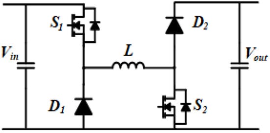
Figure 6.
Schematic of H-bridge buck–boost converter (HBBBC).
When the HBBBC operates in the buck mode, as shown in Figure 7, S1 becomes the main switch and performs PWM operation according to the task needed, and S2 becomes an auxiliary switch and always maintains the OFF state. In the boost mode, as shown in Figure 8, S1 becomes an auxiliary switch and maintains the ON state at all times, and S2 becomes the main switch and performs PWM operation according to the task needed [36,37]. As such, during the boost and buck operations, the main switch and the auxiliary switch are changed, and the operation status of the auxiliary switch is also different. In the supercapacitor charging mode described above, the discharged LIC module has a voltage of 39.2 V, and the Li-Po battery has a voltage of 44 V. Therefore, in order for the HBBBC to charge the LIC module, it must initially operate in the buck mode. As charging progresses, the voltage of the LIC module increases and becomes equal to the voltage of the Li-Po battery. Since charging is not possible in the buck mode from this section, the HBBBC must be transferred to the boost mode. During mode transfer, if the duty by the output value from one controller is applied to the buck mode and boost mode as is, a problem may occur in the converter, so a control method for mode transfer is required.
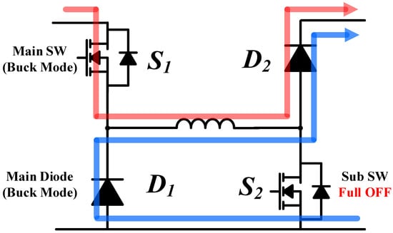
Figure 7.
Buck mode operation of H-bridge buck–boost converter.
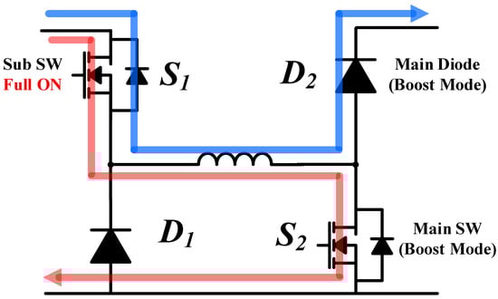
Figure 8.
Boost mode operation of H-bridge buck–boost converter.
2.3. Mode Transfer Method of H-Bridge Buck–Boost Converter (HBBBC)
In the hybrid power supply system applied in this paper, the voltage of the LIC module may be lower or higher than that of the Li-Po battery at the beginning. The HBBBC needs to charge the LIC module under any condition, and at this time, the transfer of operation mode may occur. For natural transfer of the operating mode, an accurate criterion and algorithm for changing the operating mode are required, and appropriate forward compensation is required to minimize the transient state of the converter at the moment of transfer.
Figure 9 shows the control block diagram of the HBBBC proposed in this paper for charging the LIC module. The proposed control method operates as one current controller for charging current control in the buck mode and boost mode, and the output of the controller is added to the feedforward compensation value to determine the switching state according to the size of the value. If the feedforward compensation value is less than 1, it becomes a duty value for operating as a buck converter, and if it is greater than 1, it becomes a duty value for operating as a boost converter. The mode selection block allows us to determine the operating mode of the converter through the algorithm shown in Figure 10 by receiving feedback from the input voltage, Li-Po battery voltage Vin, and the output voltage, LIC module voltage Vout.
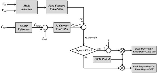
Figure 9.
Proposed control block diagram of H-bridge buck–boost converter.
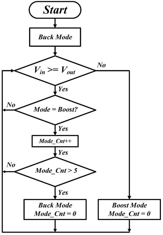
Figure 10.
Proposed mode transfer algorithm of H-bridge buck–boost converter.
If the mode is simply transferred by comparing the difference between the input voltage and the output voltage, a problem may occur in which the buck mode and the boost mode are repeatedly transferred for a short moment due to the output voltage ripple or error in the sensing value. Therefore, the Mode_Cnt variable is designated at the moment of switching from the buck mode to boost mode to prevent returning to the buck mode if the value of the variable does not reach a certain level. When the operating mode of the converter is determined with the mode selection block, the feedforward compensation value is calculated according to the determined mode. Equations (1) and (2) are formulas for calculating feedforward compensation values in the buck mode and boost mode, respectively.
Each feedforward compensation value is calculated based on the voltage transfer ratio of the buck converter and the boost converter, and FF_gain (0.1~0.4) is applied to prevent excessively large compensation values from being applied at once.
3. Simulations
Prior to the experiment, a simulation using PSIM was conducted to verify the performance of the hybrid power supply system proposed in this paper. The simulation consisted of a simulation of the mode transfer method of the HBBBC to charge the supercapacitor and an operation simulation of the hybrid power supply system. The parameters applied to the mode transfer simulation of the HBBBC are shown in Table 2, and the simulation circuit diagram is shown in Figure 11. The simulation circuit diagram of the HBBBC consists of a converter circuit part, a reference generation part, and a controller part using a DLL block. In order to simulate real-world conditions, a Li-Po battery was modeled and applied to the converter input. However, because the capacity of the LIC module could not proceed to 228 F due to the limitations of the simulation tool, it was set to 100 mF, and the simulation proceeded. In addition, to confirm the operation of the buck mode and boost mode, the initial voltage of the supercapacitor was set to 0 V and the simulation was performed.
Table 2.
Simulation parameters of H-bridge buck–boost converter.
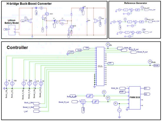
Figure 11.
Simulation circuit diagram of supercapacitor charging mode.
Figure 12 shows the simulation result waveform of the HBBBC. The initial voltage of the Li-Po battery used as the input of the converter was 44 V.
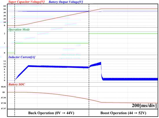
Figure 12.
Simulation waveform of supercapacitor charging mode with the proposed method applied.
In order to confirm that the battery SOC decreased as charging progressed in the battery model, the initial value of SOC was set to 88%. Since the initial voltage of the supercapacitor applied to the simulation was 0 V, when charging started, the HBBBC operated in the buck mode and charged the supercapacitor. As charging progressed, the voltage and SOC of the Li-Po battery gradually decreased, and the voltage of the supercapacitor increased. When the voltage of the Li-Po battery and the voltage of the supercapacitor became similar, the converter switched to the boost mode. At this time, since the proposed switching technique was applied, no malfunction occurred during mode conversion, and it was confirmed that no transient state occurred in the charging current due to the feedforward compensation value.
Figure 13 shows the simulation waveform when the method proposed in this paper is not applied. It can be seen through the waveform that an undershoot occurs in the inductor current at the moment the mode is switched, and a transient state continues to occur even during operation in the boost mode. If this phenomenon occurs in an actual experiment, a current exceeding the permissible value of the inductor current may flow and cause a significant problem.
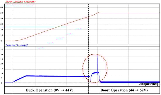
Figure 13.
Simulation waveform of supercapacitor charging mode without applying the proposed method.
Figure 14 is a circuit diagram of a simulation in which the hybrid power supply system proposed in this paper supplies power to the load side, and Table 3 shows the main parameters applied in the simulation. The Li-Po battery was implemented through modeling, and the initial voltage was set to 44.7 V. The supercapacitor was set to 53 V, 228 F, assuming a fully charged state. In addition, in order to reflect the load pattern of the drone to some extent, a buck converter-based CPL (constant power load) was applied. By varying the current controller reference of the CPL, the load pattern at the initial startup of the drone was implemented.
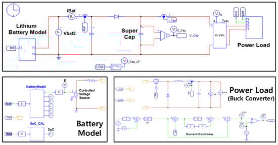
Figure 14.
Simulation circuit diagram of operation method of hybrid power supply system.
Table 3.
Simulation parameters of hybrid power supply system.
Figure 15 shows the simulation waveform of a hybrid power supply system. Since the power consumption is the most severe when the drone starts to ascend from the ground, the initial current reference of the CPL was set to 170 A in the simulation and changed to 125 A after about 1 s. The simulation was conducted under the assumption that both the Li-Po battery and the LIC module were fully charged. Initially, since the voltage of the LIC module was higher than the voltage of the Li-Po battery, the LIC module discharged alone to operate in Mode 2, supplying all the power required by the load. After that, as the LIC module was discharged over time, it became equal to the Li-Po battery voltage. From 44.7 V, it operated in Mode 3, and it can be seen that the Li-Po battery also supplied power to the load.
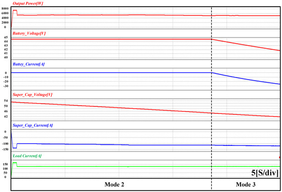
Figure 15.
Simulation waveform of hybrid power supply system.
4. Experiment Results
Figure 16 shows the configuration of the entire experimental set of the hybrid power supply system proposed in this paper, and Figure 17 shows the HBBBC hardware. The control board for controlling the converter applied was TMS320F28377S MCU. In addition, an experiment was conducted by configuring a separate touch panel to monitor and control the operation status of the entire system. Table 4 shows the parameters applied in the experiment. The Li-Po battery used in the experiment was 22.2 V (3.7 V × 6 cells), 16 Ah, and had a voltage of 44.4 V by connecting two in series. The LIC was 3.8 V, 3200 F per cell, and a module was formed by connecting 14 in series and had a voltage of 53.2 V and a capacity of 228 F.
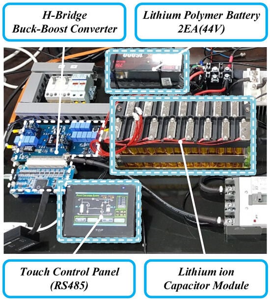
Figure 16.
Experimental setup of the proposed system.
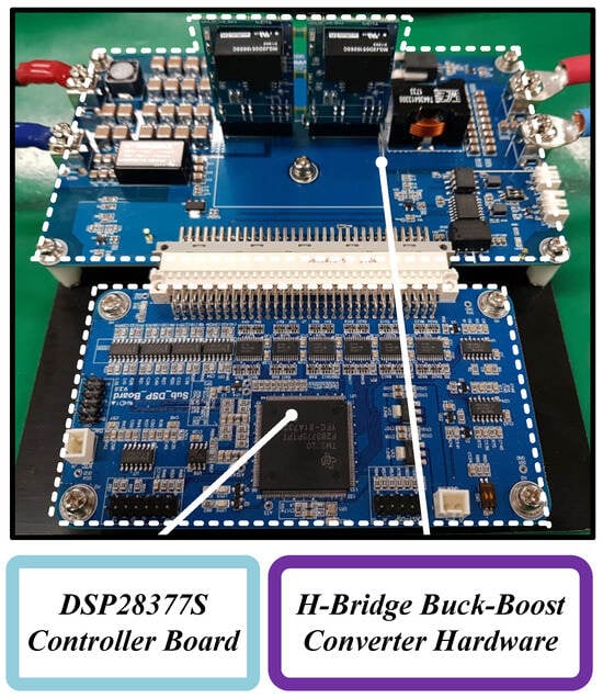
Figure 17.
Hardware of the H-bridge buck–boost converter.
Table 4.
Experimental parameters of the proposed system.
Figure 18 shows the waveform of the HBBBC transferring from the buck mode to the boost mode and charging the LIC module. Initially, the voltage of the Li-Po battery was 45.5 V, and the LIC module’s voltage was 39.5 V. The charging CC reference was 10 A, and the CV reference was 53 V. The HBBBC initially operated in the buck mode and charged the LIC module. In the section where the voltage of the Li-Po battery and the voltage of the LIC module became similar, it transitioned to the boost mode and charged the LIC up to the CV reference value. Figure 19 shows the screen of the touch panel before charging started and after charging was completed. Using the touch panel, we could check the battery, capacitor voltage, and output current before and after charging started. In addition, the operational duty information of the buck mode and boost mode can be monitored during converter operation.
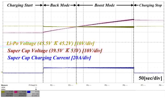
Figure 18.
Charging operation waveform (buck mode → boost mode).
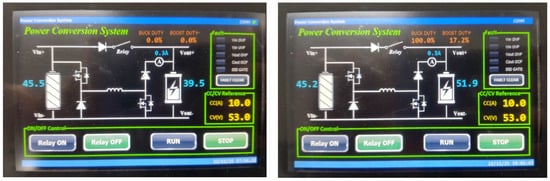
Figure 19.
Touch panel screen (buck mode → boost mode).
Figure 20 illustrates the waveform of the HBBBC charging in the boost mode in the section where the initial voltage of the LIC module was the same as that of the Li-Po battery. Figure 21 shows the state of the touch panel when charging in the boost mode.
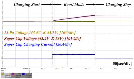
Figure 20.
Charging operation waveform (boost mode).
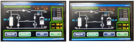
Figure 21.
Touch panel screen (boost mode).
Since the initial voltages of the Li-Po battery and the LIC module were 45.4 V and 45.3 V, respectively, it can be seen through the waveform that the converter operated in the boost mode from the beginning to charge the LIC module.
Figure 22 shows the experimental waveforms for operating Modes 2 and 3 of the hybrid power system proposed in this paper. The initial voltages of the Li-Po battery and LIC module were 44.7 V and 52 V, respectively. When a load of 5.4 kW was applied, the hybrid power supply system operated in Mode 2 in which only the LIC module was discharged and supplied power to the load. As the LIC module was discharged, when the voltage dropped to 44.7 V, which was the Li-Po battery voltage, it converted to Mode 3, and the Li-Po battery also started to discharge, so the current flowing from the LIC module to the load decreased, and the current flowing from the Li-Po battery to the load increased.
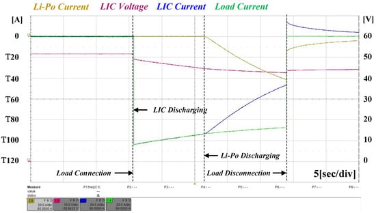
Figure 22.
Experimental waveforms of hybrid power supply system (Mode 2 and Mode 3).
5. Conclusions
In this paper, a hybrid power supply system combining a Li-Po battery and a supercapacitor (LIC) for commercial drone applications, an operating method, and a control method for an HBBBC for charging the supercapacitor (LIC) in the system are proposed.
After applying the system and method proposed in this paper, the following conclusions were drawn:
- (1)
- Among the proposed techniques, when the HBBBC mode transfer control method for charging the LIC module was applied, it could operate as one controller in the buck mode and boost mode. In addition, it was verified through simulation and experiment that the transient state did not occur at the moment the mode was transferred.
- (2)
- In the case of the operating technique of the hybrid power supply system, the pre-charged LIC module supplied power to the load preferentially in the section where high power was required for a short moment, such as the initial startup and ascending operation of the drone. Therefore, it was possible to minimize the stress applied to the Li-Po battery in a section where power consumption was high.
- (3)
- It was verified through simulations and experiments that a more stable power supply was possible because the LIC module and Li-Po battery supplied power to the load together even in the section where the power consumption of the load was reduced.
Applications using Li-Po batteries, including commercial drones, are increasing day by day, but various accidents caused by Li-Po batteries are also increasing. If the hybrid power supply system proposed in this paper is applied to these applications, it is hoped that the efficient use of Li-Po batteries will be possible.
In future studies, we will calculate the appropriate supercapacitor capacity to minimize the weight and volume of the proposed hybrid power supply system and explore the applicability of applying it to actual commercial drones to optimize performance and efficiency.
Author Contributions
K.-M.K. and Y.-S.K. conceived and designed the theory and experiment; K.-M.K. and Y.-S.K. performed the experiment; K.-M.K., Y.-S.K. and Y.-S.L. analyzed the theory; K.-M.K. wrote the manuscript; Y.-S.K. and Y.-S.L. reviewed the manuscript and searched conventional studies; C.-Y.W. and J.Y. participated in research plan development and revised the manuscript. All authors have read and agreed to the published version of the manuscript.
Funding
This work was supported by the National Research Foundation of Korea (NRF) grant funded by the Korea government (MSIP) (No. 2019R1A2C2007216).
Data Availability Statement
Not applicable.
Conflicts of Interest
Author Young-Sang Ko was employed by the company MinMax Corporation. The remaining authors declare that the research was conducted in the absence of any commercial or financial relationships that could be construed as a potential conflict of interest.
References
- Li, X.; Tupayachi, J.; Sharmin, A.; Ferguson, M.M. Drone-Aided Delivery Methods, Challenge, and the Future: A Methodological Review. Drones 2023, 7, 191. [Google Scholar] [CrossRef]
- Thibbotuwawa, A.; Bocewicz, G.; Nielsen, P.; Banaszak, Z. Unmanned Aerial Vehicle Routing Problems: A Literature Review. Appl. Sci. 2020, 10, 4504. [Google Scholar] [CrossRef]
- Rejeb, A.; Rejeb, K.; Simske, S.; Treiblmaier, H. Humanitarian Drones: A Review and Research Agenda. Internet Things 2021, 16, 100434. [Google Scholar] [CrossRef]
- Kim, J.; Kim, S.; Jeong, J.; Kim, H.; Park, J.-S.; Kim, T. CBDN: Cloud-Based Drone Navigation for Efficient Battery Charging in Drone Networks. IEEE Trans. Intell. Transp. Syst. 2018, 20, 4174–4191. [Google Scholar] [CrossRef]
- Grlj, C.G.; Krznar, N.; Pranjić, M. A Decade of UAV Docking Stations: A Brief Overview of Mobile and Fixed Landing Platforms. Drones 2022, 6, 17. [Google Scholar] [CrossRef]
- Qiao, Z.; Wang, D.; Xu, J.; Pei, X.; Su, W.; Wang, D.; Bai, Y. A Comprehensive Design and Experiment of a Biplane Quadrotor Tail-Sitter UAV. Drones 2023, 7, 292. [Google Scholar] [CrossRef]
- Scrosati, B.; Abraham, K.M.; van Schalkwijk, W.A.; Hassoun, J. (Eds.) Lithium Batteries: Advanced Technologies and Applications; John Wiley & Sons: Hoboken, NJ, USA, 2013; 44p, ISBN 1118615395. [Google Scholar]
- Chen, Y.; Kang, Y.; Zhao, Y.; Wang, L.; Liu, J.; Li, Y.; Liang, Z.; He, X.; Li, X.; Tavajohi, N.; et al. A review of lithium-ion battery safety concerns: The issues, strategies, and testing standards. J. Energy Chem. 2021, 59, 83–99. [Google Scholar] [CrossRef]
- Jiao, S.; Zhang, G.; Zhou, M.; Li, G. A Comprehensive Review of Research Hotspots on Battery Management Systems for UAVs. IEEE Access 2023, 11, 84636–84650. [Google Scholar] [CrossRef]
- Kim, J.; Choi, Y.; Jeon, S.; Kang, J.; Cha, H. Optrone: Maximizing Performance and Energy Resources of Drone Batteries. IEEE Trans. Comput. Des. Integr. Circuits Syst. 2020, 39, 3931–3943. [Google Scholar] [CrossRef]
- Zou, J.; Ben, T. Recent Advances in Porous Polymers for Solid-State Rechargeable Lithium Batteries. Polymers 2022, 14, 4804. [Google Scholar] [CrossRef]
- Almehmadi, F.A.; Alqaed, S.; Mustafa, J.; Jamil, B.; Sharifpur, M.; Cheraghian, G. Combining an active method and a passive method in cooling lithium-ion batteries and using the generated heat in heating a residential unit. J. Energy Storage 2022, 49, 104181. [Google Scholar] [CrossRef]
- Li, J.; Long, B.; Wu, H.; Hu, X.; Wei, X.; Zhang, Z.; Chai, L.; Xie, J.; Mei, H. Rapid Evaluation Model of Endurance Performance and Its Application for Agricultural UAVs. Drones 2022, 6, 186. [Google Scholar] [CrossRef]
- Marques, M.N.; Magalhães, S.A.; Dos Santos, F.N.; Mendonça, H.S. Tethered Unmanned Aerial Vehicles—A Systematic Review. Robotics 2023, 12, 117. [Google Scholar] [CrossRef]
- Jacewicz, M.; Żugaj, M.; Głębocki, R.; Bibik, P. Quadrotor Model for Energy Consumption Analysis. Energies 2022, 15, 7136. [Google Scholar] [CrossRef]
- Walendziuk, W.; Oldziej, D.; Slowik, M. Power Supply System Analysis for Tethered Drones Application. In Proceedings of the 2020 International Conference Mechatronic Systems and Materials (MSM), Bialystok, Poland, 1–3 July 2020; pp. 1–6. [Google Scholar] [CrossRef]
- Şahin, M.E.; Blaabjerg, F. A hybrid PV battery/supercapacitor system and a basic active power control proposal in MATLAB/Simulink. Electronics 2020, 9, 129. [Google Scholar] [CrossRef]
- Buller, S.; Thele, M.; De Doncker, R.W.; Karden, E. Impedance-based simulation models of supercapacitors and Li-ion batteries for power electronic applications. IEEE Trans. Ind. Appl. 2005, 41, 742–747. [Google Scholar] [CrossRef]
- Glavin, M.; Hurley, W. Optimisation of a photovoltaic battery ultracapacitor hybrid energy storage system. Sol. Energy 2012, 86, 3009–3020. [Google Scholar] [CrossRef]
- Wasim, M.S.; Habib, S.; Amjad, M.; Bhatti, A.R.; Ahmed, E.M.; Qureshi, M.A. Battery-Ultracapacitor Hybrid Energy Storage System to Increase Battery Life Under Pulse Loads. IEEE Access 2022, 10, 62173–62182. [Google Scholar] [CrossRef]
- Şahin, M.E.; Blaabjerg, F.; Sangwongwanich, A. A Comprehensive Review on Supercapacitor Applications and Developments. Energies 2022, 15, 674. [Google Scholar] [CrossRef]
- Wu, B.; Zhuo, F.; Long, F.; Gu, W.; Qing, Y.; Liu, Y. A management strategy for solar panel—Battery—Super capacitor hybrid energy system in solar car. In Proceedings of the 8th International Conference on Power Electronics—ECCE Asia, Jeju, Republic of Korea, 30 May–3 June 2011; pp. 1682–1687. [Google Scholar] [CrossRef]
- Camara, M.A. Modeling of A Hybrid Energy Storage System Supplied by a Photovoltaic Source to Feed a DC Motor. Int. J. Renew. Sustain. Energy 2013, 2, 222. [Google Scholar] [CrossRef]
- Jing, W.; Lai, C.H.; Wong, S.H.W.; Wong, M.L.D. Battery-supercapacitor hybrid energy storage system in standalone DC microgrids: A review. IET Renew. Power Gener. 2017, 11, 461–469. [Google Scholar] [CrossRef]
- Saha, R.; Dey, J.P.V. Battery and ultra-capacitor based hybrid energy storage system. In Proceedings of the IEEE 16th India Council International Conference (INDICON), Rajkot, India, 13–15 December 2019; pp. 1–4. [Google Scholar]
- Tshiani, C.T.; Umenne, P. The Impact of the Electric Double-Layer Capacitor (EDLC) in Reducing Stress and Improving Battery Lifespan in a Hybrid Energy Storage System (HESS) System. Energies 2022, 15, 8680. [Google Scholar] [CrossRef]
- Mishra, R.; Saxena, R. Comprehensive review of control schemes for battery and super-capacitor energy storage system. In Proceedings of the 2017 7th International Conference on Power Systems (ICPS), Pune, India, 21–23 December 2017; pp. 702–707. [Google Scholar] [CrossRef]
- Hajiaghasi, S.; Salemnia, A.; Hamzeh, M. Hybrid energy storage system for microgrids applications: A review. J. Energy Storage 2018, 21, 543–570. [Google Scholar] [CrossRef]
- Oussama, H.; Othmane, A.; Amine, S.M.; Amine, H.M.; Abdeselem, C.; Abdelkader, A.B. Modeling and control a DC-microgrid based on PV and HESS Hybrid Energy Storage System. In Proceedings of the Presented at the First International Conference on Smart Grids, CIREI’, Oran, Algeria, 4–6 March 2019; pp. 1–5. [Google Scholar]
- Li, F.; Xie, K.; Yang, J. Optimization and Analysis of a Hybrid Energy Storage System in a Small-Scale Standalone Microgrid for Remote Area Power Supply (RAPS). Energies 2015, 8, 4802–4826. [Google Scholar] [CrossRef]
- Suzuki, S.; Baba, J.; Shutoh, K.; Masada, E. Effective application of Superconducting Magnetic Energy Storage (SMES) to load leveling for high speed transportation system. IEEE Trans. Appl. Supercond. 2004, 14, 713–716. [Google Scholar] [CrossRef]
- Russo, A.; Cavallo, A. Supercapacitor stability and control for More Electric Aircraft application. In Proceedings of the 2020 European Control Conference (ECC), St. Petersburg, Russia, 12–15 May 2020; pp. 1909–1914. [Google Scholar] [CrossRef]
- Ganser, J.J. Hybrid Energy Storage Systems for UAV Applications. Ph.D. Thesis, Purdue University, West Lafayette, IN, USA, 1492. [Google Scholar]
- Gaboriault, M.; Notman, A. A high efficiency, noninverting, buck–boost DC-DC converter. In Proceedings of the Nineteenth Annual IEEE Applied Power Electronics Conference and Exposition, 2004, APEC ’04, Anaheim, CA, USA, 22–26 February 2004; Volume 3, pp. 1411–1415. [Google Scholar] [CrossRef]
- Sahu, B.; Rincon-Mora, G. A Low Voltage, Dynamic, Noninverting, Synchronous Buck–boost Converter for Portable Applications. IEEE Trans. Power Electron. 2004, 19, 443–452. [Google Scholar] [CrossRef]
- Rajarshi, P.; Maksimovic, D. Analysis of PWM nonlinearity in non-inverting buck–boost power converters. In Proceedings of the 2008 IEEE Power Electronics Specialists Conference, Rhodes, Greece, 15–19 June 2008; pp. 3741–3747. [Google Scholar] [CrossRef]
- Wei, C.-L.; Chen, C.-H.; Wu, K.-C.; Ko, I.-T. Design of an Average-Current-Mode Noninverting Buck–Boost DC–DC Converter with Reduced Switching and Conduction Losses. IEEE Trans. Power Electron. 2012, 27, 4934–4943. [Google Scholar] [CrossRef]
Disclaimer/Publisher’s Note: The statements, opinions and data contained in all publications are solely those of the individual author(s) and contributor(s) and not of MDPI and/or the editor(s). MDPI and/or the editor(s) disclaim responsibility for any injury to people or property resulting from any ideas, methods, instructions or products referred to in the content. |
© 2023 by the authors. Licensee MDPI, Basel, Switzerland. This article is an open access article distributed under the terms and conditions of the Creative Commons Attribution (CC BY) license (https://creativecommons.org/licenses/by/4.0/).