Abstract
The permanent magnet synchronous motor (PMSM) can be a suitable candidate for electrified propulsion in aviation. Despite the very high efficiency, heat dissipation during operation leads to performance limitations. Elevated temperatures in the electrical insulations and the magnets pose a potential safety risk that must be reduced by selective cooling. A comprehensive review is conducted to capture current research interests in cooling methods in PMSM. Cooling methods are described according to their heat transfer mechanism, grouped, and assigned to the components within the motor. Key findings of the literature reviewed are described in the context of PMSM cooling. Information on cooling media and potential combinations of cooling methods in components is gathered. Assessment parameters such as safety, weight, effectiveness, integrability, complexity and cost are defined to enable a subsequent qualitative analysis for six selected cooling methods. A point-weighted evaluation approach, according to VDI 2225, was applied to identify the most promising cooling approach for successful implementation in aviation.
1. Introduction
With the release of Fly the Green Deal [1], the Advisory Council for Aviation Research (ACARE) has responded to the European Union’s target to reduce its net carbon footprint to zero by 2050. The Fly the Green Deal represents an enhancement of previous policy ambitions, such as Vision 2020 or Flightpath 2050, by defining short-term, medium-term and long-term objectives for aviation infrastructure, operations or technology. A central element is the successful introduction of electricity or hydrogen through batteries or fuel cells, respectively. These energy sources can be used in (hybrid)-electric propulsion concepts through electric motors for thrust generation. Power levels of 0.3–1 MW for regional transport and 1–5 MW for short- and medium-range transport serve as prerequisites in many studies [2]. The simultaneous necessity of increasing the power density from approximately 6.7 kW/kg to 14.8 kW/kg by 2035 led to intensified research on electric motors since conventional design methods, cooling methods and material options have limitations [3].
1.1. Motor
The electromagnetic operating principle of an electric motor for the provision of mechanical power can vary greatly. This mainly depends on the area of application and the associated system boundary conditions. A permanent magnet synchronous motor (PMSM) is preferred in the aviation sector due to its high power density, high efficiency, high reliability and low maintenance. Radial flux PMSMs are widely used in industry and are actively being researched. Therefore, PMSMs are the main focus of this comprehensive review [4].
A radial flux PMSM mainly consists of a stator and a rotor, as depicted in Figure 1. The stator is the fixed part of the motor and consists of a coil winding wound around a core (stator teeth). The coil winding is usually arranged in a three-phase configuration and is supplied with an alternating current. The part of the windings that protrudes axially from the core is called the end windings, and the area surrounding it is the end cap, which is typically filled with air. The stator generates a rotating magnetic field in the air gap and is enclosed by a housing.
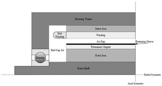
Figure 1.
Basic layout of radial flux PMSM.
The rotor is commonly located radially inside the stator and is the moving part of the motor. It consists of a cylindrical core surrounded by permanent magnets. Permanent magnets create a static magnetic field that interacts with the rotating magnetic field of the stator and sets the rotor in motion. The magnets can be integrated into the rotor iron, i.e., interior PMSM configuration, or be fixed on the rotor iron surface by a sleeve, i.e., surface PMSM configuration. To transmit the rotor power, a shaft is mounted on the rotor.
Heat generation is one of the major problems hindering the performance of the PMSM. The main sources of heat in a PMSM are copper losses, iron losses and friction losses [5]. Copper losses occur due to the electrical resistance of the copper windings in the stator slots. When current flows through the windings, resistance of the windings to the current flow results in the generation of heat. Iron losses are caused by eddy currents and hysteresis generated in the ferrous parts of the motor, especially the stator iron and rotor iron. These eddy currents occur due to induction effects as the magnetic field moves through the ferrous components. Frictional losses are a significant source of heat, especially in high-speed motors. They occur due to friction between the moving parts, primarily in the bearings. In addition, windage losses occur in the open spaces due to air friction.
The amount and distribution of the losses are significantly affected by the motor design and the implementation of a suitable cooling system. Under all circumstances, temperature-sensitive components should be kept within their operational limits. High temperatures in the insulating layer in the windings can lead to short circuits or an interruption. Excessively high temperatures in the permanent magnets lead to demagnetisation and, thus, loss of power.
1.2. Cooling Methods
The structural layout of a motor is complex, and it is not always easy to extract the heat directly from the source. This results in temperature hotspots based on the effectiveness of the cooling method. A variety of cooling methods/strategies have been proposed in the literature. Any method that brings the coolant in direct contact with the heat-generating components can be an effective cooling solution. In addition, the two-phase heat transfer can reduce the temperature gradient across these components or the motor. All cooling methods reviewed can be broadly classified as in Table 1.

Table 1.
Cooling Methods.
2. Component Cooling
A detailed literature review on PMSM cooling methods is carried out in this work. The academic databases referred for this review include journal publications from ScienceDirect, Wiley, SpringerLink, IEEE and MDPI. To confine the literature review, only journal papers/ articles published within the timeframe of 2010–2023 are selected. Specific keywords such as “Permanent Magnet Synchronous Machine”, “Thermal Management” and “Cooling” are used in the databases to gather the relevant literature. All the cooling methods reviewed are linked to the motor parts and categorised accordingly.
2.1. Shaft
The shaft is usually the innermost component in a radial flux machine. Due to the relative proximity to the temperature-sensitive permanent magnets, cooling is implemented when comparatively high heat generation in the rotor leads to the heating of the magnets. To counteract this, the shaft can be designed as a hollow shaft so that a cooling fluid could flow inside it [6,7,8,9]. The inlet and outlet of the cooling fluid can be on the same axial side or on the opposite side.
When air is used as the fluid, convective heat transfer can be enhanced by fins on the inside of the shaft [10]. It is also possible to use water–ethylene–glycol (WEG) as the cooling fluid [6,7]. Due to the improved heat dissipation when using WEG, a combination with cooling jackets can be eliminated. An operational power improvement of 20% was achieved compared to a baseline cooling jacket without shaft cooling [6]. It was demonstrated on a 130 kW motor that the heat transfer can be improved by increasing the rotational speed and was only slightly dependent on the mass flow rate [7].
A heat pipe integrated shaft is another cooling method and is commonly operated with deionised water [11]. The fluid evaporates in the electromagnetically active part of the motor and condenses axially outside. Accordingly, the shaft must have a minimum length so that condensation and evaporation result in the desired heat dissipation. Three different approaches for condensation initialisation were presented [11]: (a) spray cooling, (b) finned shaft air cooling and (c) blade-integrated shaft.
In contrast to stationary heat pipes, which rely on capillary forces, shaft-integrated heat pipes show superior performance due to centrifugal forces acting on the fluid as the driving force. Achieving the full potential of the shaft cooling methods might be difficult due to the geometry-related thermal bottleneck between the shaft and rotor iron [7]. Different literature-based shaft cooling methods are shown in Figure 2 and Figure 3a.
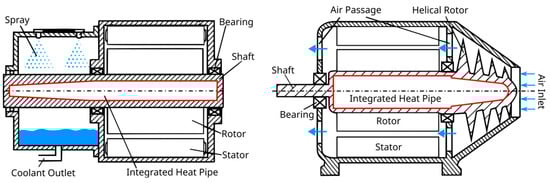
Figure 2.
Shaft-integrated heat pipe.
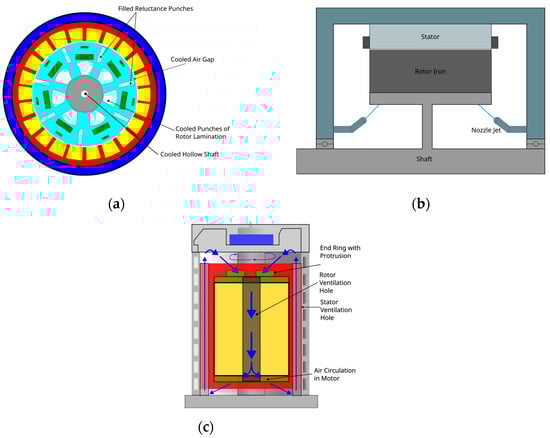
Figure 3.
Different rotor iron cooling methods: (a) lamination, heat pipes and PCM cooling methods; (b) direct oil impingement cooling; (c) air ventilation cooling.
2.2. Rotor Iron
The rotor iron is the part of the rotor laminations that is radially above the rotor shaft. It is in proximity to magnets, depending on the arrangement. Therefore, as explained in Section 2.1, the cooling system implemented in rotor iron can also avoid overheating of magnets. In general, rotor cooling methods alone are not sufficient for motor cooling and are used in combination with other methods. The effect of rotor lamination cooling, copper water heat pipes and PCM material (incorporated into rotor iron reluctance punches) on the operational limits was studied on a 125 kW peak power PMSM [6]. These methods were assessed in combination with housing cooling jackets and direct end winding cooling separately. Lamination cooling using a WEG mixture (50/50) was shown to provide the best operational limit improvement (35% at 7000 rpm). Heat pipes increase the limits by only 7.5% but eliminate piping and pump systems. A direct oil impingement cooling of rotor iron (in combination with water jackets) for a 130 kW continuous power PMSM was presented [7]. It showed a ~50 °C reduction in maximum magnet temperature compared to a conventional standalone water jacket cooling. This is possible due to the improved heat transfer coefficients from the direct impingement of the coolant onto the rotor.
An external or an internal (open or enclosed) fan can be utilised to provide forced air circulation through the rotor ducts from the ambient environment and cool the rotor iron. For a 40 kW PMSM, an internal air circulation for local permanent magnet cooling in combination with a stator water cooling jacket was proposed [12]. The flow through the vertical ventilation channels in the rotor iron was driven by flow inducers (protrusions). Parametric studies were carried out to understand the impact of protrusion dimensions on the cooling. Different literature-based rotor iron cooling methods are shown in Figure 3.
2.3. Air Gap
The air gap is one of the most sensitive parts/parameters, which can substantially produce variations in the magnetic behaviour of the motor. The gap is located between the rotor and the stator of the motor. Heat generation in the rotor is usually dissipated via the air gap to the stator and then finally to the ambient atmosphere. The air gap is not a component that is directly cooled, but the presence of an adequate air gap can facilitate convective heat transfer between the rotor and stator [6].
2.4. Stator
The stator design is typically a slotted one such that it provides a seat for the windings, which are usually arranged in a three-phase configuration. It also guides the magnetic flux in the stator iron. The number of stator slots and the number of magnetic pole pairs are key parameters in determining the mechanical and electrical performance of a motor.
A common stator cooling method in industrial applications is air cooling. The presence of radial ventilation channels allows simultaneous cooling of the stator and windings [13,14]. Variation in the opening width of the semi-closed stator slot up to a certain limit has proven to enhance the heat transfer in the motor [15]. The presence of a dual ventilation path by adding axial ducts throughout the stator yoke has been investigated to improve the thermal behaviour of the stator [16]. With this technique, a 315 kW PMSM was observed to have a maximum temperature drop of ~100 °C when compared to conventional slot ventilation cooling. Cooling channels in stator lamination can be another option for cooling. However, these can also change the magnetic flux path due to additional reluctance. The addition of an orifice plate in the stator cooling channel, which effectively redistributes the water in the stator and end windings, was tested on a 22.6 kW motor [17]. When compared to the standard air ventilation cooling, the improved design showed a temperature drop of 81.5 °C in the winding.
Enclosure of the cooling jacket around the stator has been actively used in industrial and automotive applications and has proven to be an effective cooling method. The cooling jacket (copper or aluminium design) is shrunk-fit around the stator circumference such that the large surface area allows the coolant (WEG) to flow inside the channels to carry away the heat [18]. The spiral-shaped water-cooling jacket is one of the most common types of jacket cooling methods [19]. Circumferential water-cooling jackets with an S-type design [20] and rectangular channels [21] are also common. Water–glycol has also been implemented as a working media for the cooling jacket [22]. Twisted spiral channels in the water-cooled jacket, when combined with hollow shaft cooling, for an 80 kW interior PMSM led to an average motor temperature reduction of 10% when compared to a cooling jacket with smooth channels [23]. A combination of cooling jacket (WEG/ oil) with shaft cooling (WEG/ oil) and oil end winding cooling when used in a motor of peak power range 200-kW was found to exhibit the best thermal performance for an equally distributed coolant flow rate when compared to any of the cooling methods individually or in a combination of two [24].
Direct liquid cooling by flooding the stator with a dielectric fluid, such as oil, has been shown to significantly reduce the stator temperature and provide a considerable cooling effect [25,26,27]. The stationary and rotating parts are separated by a sleeve such that the rotating parts always run dry with minimal windage losses. This idea has been implemented and tested on a 150 kW [25] and 130 kW motor [26]. Another direct liquid cooling approach involves the use of axial cooling channels in the stator yoke. The use of oil in combination with oil-flooded end windings provides favourable results for radial PMSM cooling [28]. A new inside water channel structure, in combination with slot ventilation cooling, that was able to limit the stator core temperature to 70 °C for a 300 kW motor has been proposed [14]. A direct oil-cooled PMSM with a motor rating of 90 kW was shown to produce a temperature drop of 18 °C when compared to the conventional water-cooling jacket approach [28].
Compared to the conventional cooling methods for stators, certain unconventional cooling systems, such as the use of PCM, e.g., paraffin, have been tested [29]. Heat pipes with an evaporative end along the windings and a condensation segment in the finned air-cooled enclosure make an excellent lightweight thermal system for stator cooling [30]. Incorporating a water jacket around the stator with a heat pipe and a resin potting material between the casing and end windings has been experimentally verified on a 53 kW PMSM. It showed nearly a 23 °C temperature drop [31]. Inserting water cold plates axially within the stator core increases the heat transfer area for heat dissipation. This technique, when combined with water-jacket cooling, serves as an efficient cooling strategy. The cold plate method can reduce the winding temperature further by 20 °C when compared to a standalone cooling jacket approach [32]. Different literature-based stator cooling methods are shown in Figure 4.
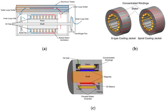
Figure 4.
Different stator cooling methods: (a) air ventilation cooling; (b) cooling jackets; (c) flooded stator cooling.
2.5. End CAP Air
The enclosed air inside the end cap is bounded by the front surfaces of the active parts, the outer surface of the shaft as well as by the housing. Also, this cavity encloses the end windings, which are typically responsible for a large proportion of the total heat generation. An active flow of air through the end cap improves the heat transfer [33]. The winding cooling effect was enhanced by 28%, improving the thermal reliability of the motor [33]. Air flows radially inwards through an inlet in the housing into the end cap cavity on one axial side of the motor and leaves the motor on the other axial side. The flow is guided around the end winding and passes through the air gap and the stator cooling duct axially.
2.6. Windings
In a typical radial PMSM, windings are wound around stator teeth through stator slots axially. These are a group of coils which carry electric current. Windings are predominantly heated because of the copper losses. Dissipation of heat can be challenging because of the location of windings and the winding insulation material, which acts as a thermal barrier.
Cooling jackets are commonly used cooling methods for windings. A scheme with channels directly passing through the stator slots in combination with circumferential micro-channel cooling jackets was tested and evaluated [18]. Stator peak temperatures for a 30 kW motor have been studied at different speeds. It was observed that the thermal limit of class H insulation (max. permissible temperature of 180 °C) is reached only around 14,000 rpm. However, cooling tubes through slots were not found to be suitable for mass production because of the complexity. A direct liquid cooling method for fractional slot concentrated windings or tooth-coil winding with trapezoidal conductors (both cast and 3D printed) was presented [34]. In addition, the suitability of different liquids (Table 2) for direct cooling was compared. A cooling method for slotless motors with cooling channels embedded into non-magnetic winding support was introduced [35]. The winding support was manufactured using high thermal conductivity plastic. It was concluded that in comparison to axial slot water jacket cooling, the embedded cooling channel method is lighter and achieves 35% higher continuous current density for an 11.5 kW machine.
Two phase or latent heat-based evaporative cooling methods are also utilised [36,37]. Both articles presented a microwicking structure for liner material, which wraps the windings in the slot. The capillary action of the wick structure drives a thin film flow axially through the slot around the windings and enables evaporative cooling by bringing the coolant into direct contact with the windings. Other potential advantages of this approach are high latent heat of evaporation, same copper fill factor and low pumping requirement. As the coolant is in direct contact with the windings, a dielectric coolant like FC-84 [36] or Novec-7200 [37] should be used. This capillary-based method might need a special coolant delivery system in the housing and an arrangement to avoid coolant flow from the stator to the rotor side [37]. A comprehensive evaluation of the proposed cooling method compared to the conventional cooling jacket method was presented [36]. It was shown that for the same current density, the peak temperatures of windings, end-windings and magnets were significantly reduced with evaporative cooling, particularly at higher current densities. This method can eliminate the cooling jackets [37]. A 3D-printed direct winding cooling channel (direct winding heat exchanger), which is in contact with stator windings using water as coolant, was proposed [38]. The cooling channel made of five different dielectric polymers was fit into the gap between neighbouring windings and tested. For a machine with 11.8 kW/kg specific power, higher current densities, i.e., 33 A/mm2 (simulations) and 20 A/mm2 (experiments), were achieved without breaching the temperature limits with the proposed method. In general, it is expected that the introduction of 3D printing will allow certain winding cooling methods to be implemented efficiently and with reduced manufacturing complexity. Several intricate cooling channel designs, arrangements and distributions, e.g., micro channels, can be set up economically. Conductor designs with varying thicknesses in the groove/slot are also achievable, which shift the thermal limits through reduced thermal resistances (higher fill factors). Simultaneously, hollow conductors can be designed more effectively both electrically (using the skin effect) and thermally (using a larger heat transfer surface area and direct connection between heat sink and source) [39]. Different literature-based winding cooling methods are shown in Figure 5.
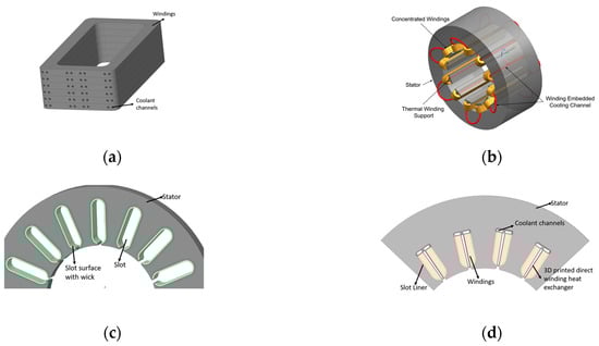
Figure 5.
Different winding cooling methods. (a) Direct liquid cooling; (b) cooling channels embedded in windings; (c) wicks promoting capillary flow evaporative cooling; (d) 3D printed direct winding cooling channel.
2.7. End Windings
The end winding is the part of the winding that protrudes axially from the stator. The front and rear-end windings are typically surrounded by air. The end windings are significant sources of heat and, therefore, require sufficient cooling.
As explained earlier, an active flow of air in the end cap can cool the end windings [33]. It is very effective to cool the end windings with a liquid channel in direct contact. Silicone rubber channels that radially split the end winding were presented [40]. In combination with conventional cooling jackets around the stator, the cooling concept showed excellent thermal properties but increased the complexity of the hydraulic system. A hotspot temperature reduction of up to 25% was achieved, and the current density was increased by 13% for class H thermal class insulation.
Highly conductive potting material between the end winding and the housing can reduce thermal resistance and cool the end windings efficiently. Suitable materials are aluminium oxide-based Ceramacast [41] and Silicone Gelatine [31,41]. Their use significantly reduces the temperatures of the end windings and, at the same time, causes a reversal of the axial temperature gradient between winding and end winding. Potting materials are always observed in combination with cooling jackets. Moreover, heat pipes can be integrated into the potting material for end winding cooling [31]. This combination resulted in a more uniform temperature distribution in the casing and in a significant increase in the running time under peak-load conditions.
Flooded cooling by immersing the end windings in the coolant is another effective cooling method for end windings [28,42]. Computational fluid dynamics (CFD) analysis shows a potential peak temperature reduction of 15 °C. Flooded cooling can lead to varying degrees of evaporation. Therefore, external cooling jackets can become obsolete and motor weight can be reduced for a 25-kW electric motor [37].
Another possibility to cool the end windings directly is to impinge them with a dielectric fluid, such as oil [43] or a hydroflourether [18,37]. Under high pressure, the cooling fluid is distributed through several nozzles along the end windings so that a large surface area is wetted. On impact, it can evaporate and provide very good cooling properties. Cooling channels for spray cooling can be located directly in the endcap or the frame, and a variable flow volume jet can be established to get the localised cooling effect in the end windings. However, reliability of this method needs to be improved by avoiding corrosion and erosion of spray nozzles [40]. Similar to the windings, the use of 3D printing can bring significant advantages in the end windings too. By designing the typically unused part of the end winding in such a way that it protrudes further into the heat sink, a better coupling with the cooling system is achieved. The coupling can be implemented using 3D printed fins considering current technology levels and in future using lattices or topology-optimised structures [39].
2.8. Frame/Housing
Frame/Housing is the stationary part enclosing all the internal parts of the motor. Housing-embedded cooling methods are some of the most commonly used motor cooling methods. This fact can be attributed to the simplicity of design compared to other methods. The main drawbacks are the internal thermal resistances hindering heat transfer from the heat source to heat sink.
Cooling jackets in the housing are a widely used motor cooling strategy [6,8,10,12,31,40,43,44,45]. It was used in combination with: (a) rotor cooling strategies [6,10], (b) rotor iron ventilation cooling [12] and (c) end winding cooling [31,40,43,44]. A coolant circuit through which the coolant flows from the housing to a hollow shaft was presented [8]. The improvements in motor cooling performance with the combination of these methods are described in the sections above.
Integration of cooling fins on the casing is a common practice for motor cooling in industrial applications. As this method is used with air, it might not be sufficient to maintain limiting temperatures for high power-dense applications. A fin-based cooling approach was implemented for different motors [46,47].
A hollow motor casing to accommodate PCM (paraffin) and eliminate complex cooling jacket circuits in the housing was presented [48]. A similar arrangement with additional fins over the casing was shown [29,49,50]. It was concluded that the temperature of the casing and PMSM can be controlled more effectively in a small range and for longer time compared to conventional methods using PCM, avoiding sudden rise or drop in temperatures. Furthermore, the peak temperature was shown to reduce depending on the duty cycle and re-solidification time of the PCM. Cooling using water–acetone-based closed loop pulsating heat pipes incorporated into casing was proposed [51]. Parametric studies were carried out to derive the optimum working fluid mixture. A 33.3 °C reduction in motor temperature and a 31% reduction in thermal resistance was achieved at optimum working condition.
An overview of all cooling methods with their associated locations, fluids and combinations is shown in Table 2.
Table 2.
Summary of all the cooling methods.
Table 2.
Summary of all the cooling methods.
| Location | Name | Fluid | Combination | |
|---|---|---|---|---|
| Rotating | Shaft | Finned Hollow Shaft [10] Hollow Shaft [6,7,8,9,24] | Air [8,9,10] WEG [6,7,24] Oil [24] Insulation Oil C15 [8] | Cooling Jacket (Frame) [8,10] Cooling Jacket (Stator) [6,24] Flooded Cooling (EW) [6] |
| Heat Pipe [7,11] | Gas or Liquid [7] Coolant [11] | |||
| Rotor Iron | Heat Pipe [6,7] | WEG [6] | Cooling Jacket (Stator) [6] Flooded Cooling (EW) [6] | |
| PCM [6] | Custom Material [6] | Cooling Jacket (Stator) [6] Flooded Cooling (EW) [6] | ||
| Lamination Cooling [6] | WEG [6] | Cooling Jacket (Stator) [6] Flooded Cooling (EW) [6] | ||
| Impingement Cooling [7] | Oil [7] | Cooling Jacket (Frame) [7] | ||
| Ventilation Cooling [12] | Air [12] | Cooling Jacket (Stator) [12] | ||
| Air Gap | Ventilation Cooling [6] | Air [6] | Cooling Jacket (Stator) [6] Flooded Cooling (EW) [6] | |
| Non-Rotating | Stator | Cold Plates [32] | Water [32] | |
| Cooling Jacket [6,12,18,19,20,21,22,23,24,40,43] | Water [19,20,21,23,24,39,43] Water Glycol [22] WEG [6,18] Oil [18,24,43] | Hollow Shaft [6,24] Heat Pipe (Rotor Iron) [6] PCM (Rotor Iron) [6] Lamination Cooling (Rotor Iron) [6] Ventilation Cooling (Air Gap) [6] Flooded Cooling (EW) [6] Ventilation Cooling (Rotor Iron) [12] Flooded Cooling (EW) [43] | ||
| Flooded Cooling [25,26,27] | Oil [25,26,27] | |||
| Ventilation Cooling [13,14,15,16] | Air [13] | Cooling Channel (Stator) [14] | ||
| Heat Pipe [30,31] | Water [30] | Cooling Fins (Frame) [30] Potting Material (EW) [31] Cooling Jacket (Frame) [31] | ||
| PCM [29] | Paraffin [29] | Cooling Fins (Frame) [29] | ||
| Cooling Channel [14,17,28] | Water [14,17,28] Oil [28] | Ventilation Cooling (Stator) [14] | ||
| End Cap Air/Area | Ventilation Cooling [33] | Air [33] | ||
| Windings | Evaporation Cooling [36,37] | Dielectric Fluid (FC-84) [36] Novec-7200 [37] | ||
| Cooling Channel [18,34,35,38] | Oil [18] Perfluoropolyether (Galden HT135) [34] Silicon Fluid (Syltherm 800) [34] Synthetic Hydrocarbon Fluid (TherminolD12) [34] Deionised Water [34] Deionised Water + Glycol [34] Water [38] WEG [35] | Cooling Jacket (Stator) [18] | ||
| End Windings | Evaporation Cooling [18] | Oil [18] | ||
| Impingement Cooling [42] | Oil [43] | Cooling Jacket (Stator) [43] | ||
| Cooling Channel [40] | Water Glycol [40] | Cooling Jacket (Stator) [40] | ||
| Potting Material [31,41,44] | Silicone Gelatin [31,41,43] Ceramacast 675N [41] | Cooling Jacket (Frame) [31,44] Heat Pipe [31] | ||
| Ventilation Cooling [33] | Air [33] | |||
| Flooded Cooling [6,24,28,37,42] | Oil [24,28,42] WEG [6] Novec–7200 [37] | Hollow Shaft [6,24] Cooling Jacket (Stator) [24] Cooling Channel (Stator) [28] | ||
| Frame/Housing | Cooling Jacket [6,7,8,10,31,43,44,45] | Water [7,8,10,31,44] WEG [6] Oil [8,43,45] | Lamination Cooling [6] PCM (Rotor Iron) [6] Heat Pipe (Shaft) [6] Hollow Shaft [6,8] Impingement Cooling (Rotor Iron) [7] Finned Hollow Shaft [10] Heat Pipe (Stator) [31] Potting Material (EW) [31,44] Impingement Cooling (EW) [43] | |
| PCM [29,47,48,49] | Paraffin [29,48,49,50] | Cooling Fins [29,48,49,50] | ||
| Heat Pipe [51] | Water-Acetone [51] | |||
| Cooling Fins [29,46,47,48,49,50] | Air [29,46,47,48,49,50] | Heat Pipe [30] PCM [29,48,49,50] | ||
3. Qualitative Assessment of Cooling Methods for Aerospace Applications
Due to the strongly differing boundary conditions of the cooling concepts presented, a qualitative assessment of the aviation sector needs to be carried out. For this purpose, a point-weighted assessment approach described and recommended in VDI 2225 is used [52]. The assessment parameters required and derived from the analysed references are safety, weight, effectiveness, integrability, complexity and costs.
The descriptions and their relative weighting are explained in Section 3.1 and summarised in Section 3.2. If one assessment parameter is more important than another, it is given a “+” in its row, otherwise a “−”. In the case of equal importance, there is an “o”. The ratio of the total number of ‘+’s in each row to total number of ‘+’s in the entire table is considered to be the weighting factor of that parameter.
Furthermore, six cooling concepts were chosen, which are evaluated by the authors rating the respective assessment parameters. The choice of concepts and the description of the characteristics are described in Section 3.2. The best rating is 5, the worst is 1 [53,54]. The sum product of the weighting factor and the individual assessment parameter rating represents the final rating. The higher the final score, the more suitable the cooling concept is for successful implementation in aviation.
3.1. Assessment Parameters
The successful implementation of electrical components in aerospace propulsion systems depends largely on increasing the power density of the system. Since the achievable power in operation is limited by the maximum permissible temperature, an increase in power and power density is only possible if sufficient cooling is provided while keeping the weight constant or lower.
The following assessment parameters are used for a qualitative assessment. They are described below and have been relatively assessed towards their suitability and applicability in (hybrid)-electric aviation.
3.1.1. Safety/Reliability
The safety and reliability of the cooling system depend on the successful operation of the individual components in the system. Depending on the type of cooling system, different components used for motor cooling are pumps, fans, pipes, valves, phase change materials, etc. It is possible that a failure or a critical event in one or a combination of these components results in a cooling system failure. Also, the possibility of the occurrence of such events increases with increasing time in service or operation. Therefore, the number and frequency of such critical events or components can give a preliminary qualitative understanding of the safety and reliability of the cooling system [54]. Alternatively, the probability of occurrence of such events can be determined to estimate the impacts, e.g., machine downtime [55,56].
The qualitative assessment in this paper presents the components of cooling systems and their critical events for different types of cooling methods. The potential for failure of the overall system is assessed based on engineering judgment and available information in the literature. The evaluation of the cooling system broadly covers the below-mentioned aspects:
- Cooling system failure and its mitigation;
- Maintenance due to additional parts for cooling;
- Overall system reliability when multiple cooling methods are used.
Safety is the top priority in aerospace applications. Therefore, the authors assumed safety to be relatively more important than all the other assessment parameters in this study, carrying more weightage.
3.1.2. Weight
The weight of a chosen cooling method must be as low as possible in order to maximise the power density of the electric motor and its cooling performance. It is impacted by the choice of cooling media, material and additional devices. Cooling media such as gases (typically air), liquids (with and without phase change) and heat-conducting solids (potting material) can be used for motors. Depending on the choice of cooling method, different materials that can be used for enhancing heat transfer alter the overall system weight. Based on the cooling strategy, additional devices such as pumps, blowers, heat exchangers, control systems, pipes, reservoirs and sealings increase the system weight.
The optimal selection of the aforementioned parameters to effectively implement a cooling method is crucial to reduce the system weight. Weight can have an impact on the power densities, efficient energy consumption, drag, range of the aircraft and costs. Therefore, weight is considered to be the second most important parameter in this assessment.
3.1.3. Effectiveness
The cooling concepts presented can each be traced back to one of the three basic principles:
- Heat transfer enhancement;
- Distributed cooling;
- Relocation of the high-temperature zones.
Thus, they contribute differently to the achievement of the thermal objectives. Typical measures to increase heat transfer include stagnation point effect (impingement cooling), phase change (evaporation/condensation), hydraulic diameter reduction, etc. Distributed cooling provides uniform cooling of the motor components, which should reduce the temperature gradient as well as the thermal stress introduced by it. Relocation of the high-temperature zones using potting material, heat pipes, etc., also achieves a similar objective.
The cooling efficiency is assessed by taking its proximity to critical components and typical heat transfer coefficients into account. With increasing proximity of critical components to cooling, the thermal resistance decreases so that more effective cooling can be achieved. Relocation of high-temperature zones by heat-conductive materials can further increase the effectiveness and compactness of the active system. The magnitude of cooling can be put into perspective by means of convective heat transfer coefficients. The higher the heat transfer coefficient, the better the cooling. Differences in heat transfer coefficient can be caused by different fluids, geometries and flow characteristics. Table 3 shows a qualitative comparison between different convective heat transfer processes.
Table 3.
Convective heat transfer coefficients based on [57].
Highly effective cooling methods aim to achieve higher current densities, which impact the motor size, power density and temperature gradients, but not at the cost of safety and weight [58]. Therefore, effectiveness is assumed to be the most relevant after safety and weight.
3.1.4. Integrability
Different scales/parameters can be used both at the component and system level to qualitatively assess the integrability of a cooling method. Integrative complexity refers to the complexity of the underlying technology such that certain designs are not always easily installable in a particular electric motor. The integrability at the component level refers to the spatial accommodation of the cooling method in the motor. Integration in the outer and thus static parts is considered easier than in the inner or rotating parts. A cooling method with higher integrability can be implemented with less effort in different motor topologies (axial flux, transversal flux).
Combining the motor cooling methods with other subsystems, e.g., power electronics (PE), is rapidly progressing due to the increasing demand for cooling power requirements [59]. However, this integration is challenging. In some compact commercial products, the motor and inverter are usually integrated as a single unit, and they interact with each other thermally. Thus, the complete thermal modelling and analysis for the integrated system is very important [60].
The highly integrated cooling method increases the compactness of the design and potentially reduces the weight. Such methods are suitable for aviation applications and are preferred. Compromise on integrability can be made by improving the effectiveness.
3.1.5. Complexity
A single cooling approach is not always suitable for high power density applications, e.g., the aviation industry. Industrial applications make use of a combination of multiple cooling strategies in order to develop better cooling capabilities, i.e., temperature distribution. Hybrid cooling methods can outperform individual cooling methods but, at the same time, pose a problem of complexity. Extra components add to the overall complexity of the system, which, in turn, increases the weight, costs, etc. Active cooling methods, though more effective than passive methods, need additional pumping and controlling equipment, which increases the overall system complexity. The presence of more parts and complicated pipeline connections in the cooling architecture could cause problems in the sealing structure and, hence, the system’s safety. Certain non-conventional cooling designs have challenging geometries and are difficult to manufacture, which raises the level of complexity of a cooling mechanism.
Complexity inherently depends on the aforementioned assessment parameters and is partly analysed under those categories. Therefore, it is assumed to have a lower relevance compared to them.
3.1.6. Costs
The costs of a motor cooling system can be interpreted as installation and operational costs. Installation costs are one-time expenses to set up the cooling method. These include design, material, fluids, manufacturing and assembling costs. Operational costs are the expenses incurred during the active service of the cooling method. These can be energy costs of the control system, i.e., pumps, fans and sensors. Maintenance and repair of such components are also accounted as a part of operational costs.
Active cooling methods are expected to have higher operational costs during their lifetime, whereas installation costs dominate passive cooling methods. A safe, lightweight and effective cooling method is crucial for developing high-power density motors, which are necessary for electric aviation. Based on the current technology readiness level (TRL) of the motors and their cooling methods, the current priority is enabling the technology rather than the costs. Therefore, cost is given the least priority in this study.
3.2. Results
3.2.1. Selection of Cooling Methods
Cooling methods selection for the scope of this research is done on the basis of certain criteria that can or could be applicable to aerospace applications. Literature references provide significant studies on the selected cooling techniques and their description. The selection of cooling methods for further assessment is broadly based on:
- Thermal behaviour of methods by keeping in mind localised cooling effect of these strategies, heat transfer phenomena and the choice of the working fluids;
- Motor parts involved in a cooling strategy inherently govern the complexity of the system and, hence, the safety;
- TRL to judge the industrial applicability of a cooling method.
The cooling methods selected for the assessment in this paper are:
- Cooling jacket;
- Cooling jacket + Potting material;
- Flooded stator with axial flow channels;
- Hollow shaft + End winding spray (liquid) cooling;
- Cooling jacket + Integral heat pipe on rotor side;
- Rotor lamination cooling (air) + End winding cooling channels.
Each selected concept can be customised and improved with respect to the assessment parameters. The following assessment assumes a standard configuration as described in the literature.
3.2.2. Assessment of the Cooling Methods
Cooling jacket
The cooling jacket method is one of the most widely used motor cooling methods. The critical components of this method include piping, pumps, valves, etc. Most of these components are readily available in the market, have high reliability and need relatively low maintenance. As observed, this is the most commonly used cooling method, so the TRL of this method is high. Any failure in the cooling jacket may lead to cooling system failure as there is no redundancy or back up. The weight contributors in this method are the liquid coolant, auxiliary components and piping system.
The heat transfer coefficients for a liquid flow are typically higher compared to gases. However, the uneven temperature distribution inside the motor still persists when using the standalone cooling jacket method and leads to local hotspots. This is mainly because of the higher thermal resistance (longer heat transfer path) between heat sources and cooling surfaces. Integrating this method into the motor is the easiest, considering the location. With proper design and integration, it can be used to cool the other systems in proximity to the motor simultaneously, e.g., power electronics.
This standalone cooling method is assumed to have minimum installation and manufacturing complexity. However, the flow control system will add additional complexity. Liquid costs, equipment/material costs and installation costs are the initial fixed costs. The operational costs include the energy costs needed to run the equipment. The overall cost is assumed to be moderate.
Cooling jacket + Potting material
This cooling method is similar to the cooling jacket method except for the potting material. Consequently, all the conclusions made here are in comparison with the cooling jacket method. The number of critical components is assumed to be the same. The TRL of potting material is lower. The maintenance effort needed is considered to be more because of the potting material, which can only be replaced and recycled but not repaired. In case of the cooling jacket failure, potting material provides comparatively better heat dissipation. It also adds up to the weight.
The heat transfer coefficients that are observed in the cooling jacket method can also be achieved with this method. The potting material is in direct contact with the end windings, providing better temperature distribution. Therefore, the thermal performance is superior to the standalone cooling jackets. The addition of potting material in the endcap cavity is an additional integrability challenge. Manufacturing of the potting material increases the complexity. Finally, the material and installation costs are higher, and the other costs remain the same.
Flooded stator with axial flow channels
The flooded stator concept with an axial flow channel is a very promising cooling concept. It provides high cooling capabilities due to forced liquid cooling in proximity to the heat sources and, therefore, lowering the potential of hot spots within a PMSM. Compared to the other five cooling methods assessed here, low maximum temperatures can be expected in this method. However, no redundant cooling method is acting in combination and, therefore, poses a potential safety problem. Besides pumps and valves, additional sealings and the sleeve increase the number of critical components, the maintenance and installation effort. The requirement of a dielectric coolant limits the choice of fluids, which also results in relatively high installation and development costs, which are accompanied by moderate operating costs.
The concept raises a difficulty in terms of integrability into the motor itself since the internal components are not easily accessible, and cooling could limit high slot-filling factors. This cooling method can be adapted to other machine architectures like axial or transversal flux with additional engineering/design effort. Nevertheless, by means of connections on the outside of the stator in radial flux machines, other electrical subsystems can be easily included in a centralised cooling circuit. As with every active cooling concept, it must be controlled, which raises complexity. The additional weight due to coolant and components is assumed to be low.
Hollow shaft + End winding spray cooling
Liquid spray cooling with a dielectric fluid (e.g., oil) is a purely convective heat exchange phenomenon [60]. The idea of spray cooling is to utilise the phase change properties such that high evaporative heat transfer coefficients can be achieved. When combined with hollow shaft cooling, the cooling channels for both the shaft and end windings can be linked together to have a hybrid cooling with enhanced heat transfer. These two cooling methods can act as a backup in case one method fails and potentially increases safety. However, the impact of frequent impingement of coolant with the electrical insulation system increases the possibility of corrosion and mechanical degradation of wire coatings.
The design, manufacturing, installation and maintenance for a shaft cooling method with end windings spray cooling is essentially quite complex because of the presence of precision nozzles, cooling channels, pumping and sealing equipment. These components also result in integration challenges within the motor and other subsystems which share the cooling method. The addition of auxiliary equipment increases the material and installation costs and also makes the component weight comparable to the cooling jacket method. However, the volume of fluid required is less, resulting in an overall weight advantage.
Cooling jacket + Integral heat pipe on rotor side
Combining conventional stator cooling jackets with shaft-integrated heat pipes offers another solution for effectively cooling rotating and stationary components. With its excellent, effective heat conductivity, resulting from the physical working principle, the heat pipe permits the axial relocation of hotspots that are otherwise difficult to cool. The cooling needed for condensation in the heat pipe can either be provided by the cooling jacket working fluid or by an additional design measure using air (considered in this study). In both cases, high efficiency is achieved at the costs of design complexity as well as overall weight and potentially increases the additional losses due to the exposure of heat pipe conductive materials to varying magnetic fields. Although heat pipes are typically lightweight and do not add much to the weight of the system, the axial extension of the shaft and its design modifications, combined with the auxiliaries of the liquid cooling, results in a high expected total weight.
The complexity in the design, manufacture and integration of a heat pipe into a rotating component has a negative effect on the installation costs. Operating and maintenance costs are low due to their passive nature and are primarily determined by the actively controlled cooling jackets. The integration of stator cooling is simple and can lead to compatibility and synergy with adjacent components and their cooling systems.
In general, heat pipes do not affect the cycle life of the system and its reliability. A second cooling medium for condensation in the heat pipe can even increase the cooling redundancy. With the combination of integral heat pipes and liquid cooling, leakage or failure of the critical components can lead to failure or impairment of both systems.
Rotor lamination cooling (air) + End winding cooling channels
Forced air cooling in the rotor lamination combined with cooling channels in the end windings is another promising PMSM cooling approach. Both the stationary and rotating parts of the motor can be cooled simultaneously. When compared to passive air cooling, forced air cooling provides higher heat transfer coefficients and enhances axial fluid flow to bring the overall motor temperature down. In addition to this, a coolant pipe through the end windings promotes direct end winding cooling and hot spot mitigation.
The combination of two active cooling methods potentially increases the safety margin. However, the water vapour and certain foreign particles that enter the motor along with the air flow can lead to mechanical failures, corrosion and other safety hazards. The design, manufacturing and integrability of the end winding cooling channels is a challenging task. Using two different types of fluids (air and liquid) allows optimal integration of the cooling method with other subsystems. Flow controlling equipment, like pumps, fans and sealing components, increases the complexity, weight and installation costs. Mitigating the aforementioned safety risks necessitates additional maintenance and operational costs.
The assessment of the above-mentioned parameters and cooling methods is summarized in Table 4.
Table 4.
Assessment parameter weightage and assessment of cooling method.
4. Conclusions
A detailed review of the PMSM cooling methods is carried out. The different cooling methods shown in the literature can be broadly classified based on the fundamental heat transfer mechanisms. The major difference amongst the methods is the location of cooling.
A qualitative assessment of six different cooling methods selected is conducted to study their usability in aerospace applications (comparatively). Safety is given the highest weightage and costs the least among the assessment parameters. The cooling jacket method, which is widely used in the industry, is selected as a baseline in this work. The six different methods performed relatively similarly based on the overall score. However, these methods, when compared against each assessment parameter individually, provided further insights. The flooded stator and hollow shaft + end winding evaporation cooling are the least preferred when safety is considered due to additional components, e.g., sealings, spray equipment, etc., and related maintenance. These two methods, on the other hand, are assessed to be performing better than other methods in terms of weight. All the other methods have relatively comparable scores in safety and weight.
The methods that have direct access to the heat generation location, in general, have proved to be the best in terms of minimising the temperature hotspots and maximum temperatures. The cooling jacket located on the frame cannot completely eliminate hot spots, whereas all the other methods are relatively better in providing uniform temperature distribution. Integrability and complexity increase when the internal parts of the motor need to be accessed. Cooling jacket and cooling jacket + potting material are considered easily integrable and have a less complex design. All the other methods are relatively worse in this regard. Hollow shaft + end winding evaporative spray cooling is assumed to be the most costly of all the methods due to additional equipment and maintenance required.
This study provides a comprehensive framework to assess the cooling methods for their use in aerospace applications. A detailed literature review of the most recent PMSM cooling technologies is presented. A quantitative analysis with modelling and analytical results is planned for the future to further justify the findings of this work.
Author Contributions
Conceptualisation, P.K., D.S., K.R.K., T.X. and K.H.; methodology, P.K., D.S., K.R.K., T.X. and K.H.; formal analysis, P.K., D.S., K.R.K., T.X. and K.H.; investigation, P.K., D.S., K.R.K., T.X. and K.H.; writing—original draft preparation, P.K., D.S., K.R.K., T.X. and K.H.; writing—review and editing, P.K., D.S., K.R.K., T.X. and K.H.; visualisation, P.K., D.S., K.R.K., T.X. and K.H.; supervision, K.H. All authors have read and agreed to the published version of the manuscript.
Funding
This research received no external funding.
Data Availability Statement
Data are contained within the article.
Acknowledgments
The authors would like to thank Jonas Franzki from the Institute for Electrical Machines, Traction and Drives of the TU Braunschweig for his support.
Conflicts of Interest
The authors declare no conflict of interest.
References
- European Commission. Fly the Green Deal, Europe’s Vision for Sustainable Aviation; Report of the Advisory Council for Aviation Research and Innovation in Europe (ACARE); European Commission: Brussels, Belgium, 2022. [Google Scholar]
- Novelli, P. IMOTHEP* European Project: An Investigation of Hybrid Electric Propulsion for Commercial Aircraft. In Proceedings of the AIAA AVIATION 2023 Forum, San Diego, CA, USA, 12–16 June 2023. [Google Scholar] [CrossRef]
- König, P.; Müller, P.; Höschler, K. Assessment of (Hybrid)-Electric Drive-Train Architectures for Future Aircraft Applications. J. Phys. Conf. Ser. 2023, 2526, 012023. [Google Scholar] [CrossRef]
- Sahoo, S.; Zhao, X.; Kyprianidis, K. A Review of Concepts, Benefits, and Challenges for Future Electrical Propulsion-Based Aircraft. Aerospace 2020, 7, 44. [Google Scholar] [CrossRef]
- Germar, M.; Bernd, P. Grundlagen Elektrischer Maschinen, 10th ed.; Wiley-VCH: Weinheim, Germany, 2014; ISBN 3-527-41205-1. [Google Scholar]
- Groschup, B.; Komissarov, M.; Stevic, S.; Hameyer, K. Operation Enhancement of Permanent Magnet Excited Motors with Advanced Rotor Cooling System. In Proceedings of the ITEC 2019–2019 IEEE Transportation Electrification Conference and Expo, Detroit, MI, USA, 19–21 June 2019; pp. 10–15. [Google Scholar] [CrossRef]
- Nonneman, J.; Van Der Sijpe, B.; T’Jollyn, I.; Vanhee, S.; Druant, J.; De Paepe, M. Evaluation of High Performance Rotor Cooling Techniques for Permanent Magnet Electric Motors. In Proceedings of the 2021 IEEE International Electric Machines and Drives Conference, IEMDC 2021, Hartford, CT, USA, 17–20 May 2021. [Google Scholar] [CrossRef]
- Lee, K.H.; Cha, H.R.; Kim, Y.B. Development of an Interior Permanent Magnet Motor through Rotor Cooling for Electric Vehicles. Appl. Therm. Eng. 2016, 95, 348–356. [Google Scholar] [CrossRef]
- Gai, Y.; Kimiabeigi, M.; Chong, Y.C.; Widmer, J.D.; Goss, J.; Sanandres, U.; Steven, A.; Staton, D.A. On the Measurement and Modeling of the Heat Transfer Coefficient of a Hollow-Shaft Rotary Cooling System for a Traction Motor. IEEE Trans. Ind. Appl. 2018, 54, 5978–5987. [Google Scholar] [CrossRef]
- Jaeger, M.; Ruf, A.; Hameyer, K.; Tongeln, T.G. Von Thermal Analysis of an Electrical Traction Motor with an Air Cooled Rotor. In Proceedings of the 2018 IEEE Transportation and Electrification Conference and Expo, ITEC 2018, Long Beach, CA, USA, 13–15 June 2018; pp. 194–200. [Google Scholar] [CrossRef]
- Denkena, B.; Bergmann, B.; Klemme, H. Cooling of Motor Spindles—A Review. Int. J. Adv. Manuf. Technol. 2020, 110, 3273–3294. [Google Scholar] [CrossRef]
- Lee, J.; Lee, N.; Um, S. Thermofluidic Analysis of Interior Permanent Magnet Synchronous Motors with Internal Air Circulation by Protrusion-Shaped Flow Inducers for Effective Thermal Management. J. Mech. Sci. Technol. 2020, 34, 3415–3426. [Google Scholar] [CrossRef]
- Fei, W.; Luk, P.C.K.; Wu, D.; Xia, B. Approximate Three-Dimensional Finite Element Analysis of Large Permanent Magnet Sychronous Generators with Stator Radial Ventilating Ducts. In Proceedings of the IECON 2013-39th Annual Conference of the IEEE Industrial Electronics Society, Vienna, Austria, 10–13 November 2013; pp. 7313–7318. [Google Scholar] [CrossRef]
- Wan, Y.; Li, Q.; Guo, J.; Cui, S. Thermal Analysis of a Gramme-Ring-Winding High-Speed Permanent-Magnet Motor for Pulsed Alternator Using CFD. IET Electr. Power Appl. 2020, 14, 2202–2211. [Google Scholar] [CrossRef]
- Tang, H.; Zhang, M.; Dong, Y.; Li, W.; Li, L. Influence of the Opening Width of Stator Semi-Closed Slot and the Dimension of the Closed Slot on the Magnetic Field Distribution and Temperature Field of the Permanent Magnet Synchronous Motor. IET Electr. Power Appl. 2020, 14, 1642–1652. [Google Scholar] [CrossRef]
- Cao, Z.; Li, W.; Zhang, X.; Fan, Y.; Zeng, J. Influence of Single/Dual Ventilation Path on Fluid Field and Temperature Field of HVLSSR-PMSM with Air-Cooled Hybrid Ventilation Systems. Energies 2018, 11, 1343. [Google Scholar] [CrossRef]
- Li, L.; Zhu, G.; Zhao, Y.; Jia, N.; Xue, M.; Li, Y.; Rd, B.; District, X. Design and Analysis of Different Cooling Schemes of a Flux-Modulated Permanent Magnet in-Wheel Motor for Electric Vehicle Applications. IET Electr. Power Appl. 2021, 15, 348–358. [Google Scholar] [CrossRef]
- El-Refaie, A.M.; Alexander, J.P.; Galioto, S.; Reddy, P.; Huh, K.K.; De Bock, P.; Shen, X. Advanced High Power-Density Interior Permanent Magnet Motor for Traction Applications. In Proceedings of the 2013 IEEE Energy Conversion Congress and Exposition, ECCE 2013, Denver, Colorado, USA, 15–19 September 2013; pp. 581–590. [Google Scholar] [CrossRef]
- Wan, Z.; Sun, B.; Wang, X.; Wen, W.; Tang, Y. Waterway Design of an External Rotor Permanent Magnet Synchronous Generator. Heat Mass Transf. 2020, 56, 1249–1261. [Google Scholar] [CrossRef]
- Tang, Y.; Sun, S.; Yu, W.; Hua, W. Thermal Analysis of Water-Cooling Permanent Magnet Synchronous Machine for Port Traction Electric Vehicle. Electronics 2023, 12, 734. [Google Scholar] [CrossRef]
- Wu, S.; Zhou, J.; Zhang, X.; Yu, J. Design and Research on High Power Density Motor of Integrated Motor Drive System for Electric Vehicles. Energies 2022, 15, 3542. [Google Scholar] [CrossRef]
- Roy, P.; Bourgault, A.J.; Towhidi, M.; Song, P.; Li, Z.; Mukundan, S.; Rankin, G.; Kar, N.C. An Algorithm for Effective Design and Performance Investigation of Active Cooling System for Required Temperature and Torque of PM Traction Motor. IEEE Trans. Magn. 2021, 57, 8201507. [Google Scholar] [CrossRef]
- Wu, P.S.; Hsieh, M.F.; Cai, W.L.; Liu, J.H.; Huang, Y.T.; Caceres, J.F.; Chang, S.W. Heat Transfer and Thermal Management of Interior Permanent Magnet Synchronous Electric Motor. Inventions 2019, 4, 69. [Google Scholar] [CrossRef]
- Lehmann, R.; Künzler, M.; Moullion, M.; Gauterin, F. Comparison of Commonly Used Cooling Concepts for Electrical Machines in Automotive Applications. Machines 2022, 10, 442. [Google Scholar] [CrossRef]
- La Rocca, A.; Xu, Z.; Arumugam, P.; Pickering, S.J.; Eastwick, C.N.; Gerada, C.; Bozhko, S. Thermal Management of a High Speed Permanent Magnet Machine for an Aeroengine. In Proceedings of the 22nd International Conference on Electrical Machines, ICEM 2016, Lausanne, Switzerland, 4–7 September 2016; pp. 2732–2737. [Google Scholar] [CrossRef]
- Wang, R.; Fan, X.; Li, D.; Qu, R.; Li, L.; Zou, T. Convective Heat Transfer Characteristics on End-Winding of Stator Immersed Oil-Cooled Electrical Machines for Aerospace Applications. IEEE Trans. Transp. Electrif. 2022, 8, 4265–4278. [Google Scholar] [CrossRef]
- Ullah, S.; Winterborne, D.; Lambert, S.M. Next-Generation Integrated Drive: A High Power Density Permanent Magnet Synchronous Drive with Flooded Stator Cooling. J. Eng. 2019, 2019, 4231–4235. [Google Scholar] [CrossRef]
- Guo, F.; Zhang, C. Oil-Cooling Method of the Permanent Magnet Synchronous Motor for Electric Vehicle. Energies 2019, 12, 2984. [Google Scholar] [CrossRef]
- Wang, J.X.; Li, Y.Z.; Wang, S.N.; Zhang, H.S.; Ning, X.; Guo, W. Experimental Investigation of the Thermal Control Effects of Phase Change Material Based Packaging Strategy for On-Board Permanent Magnet Synchronous Motors. Energy Convers. Manag. 2016, 123, 232–242. [Google Scholar] [CrossRef]
- Fang, G.; Yuan, W.; Yan, Z.; Sun, Y.; Tang, Y. Thermal Management Integrated with Three-Dimensional Heat Pipes for Air-Cooled Permanent Magnet Synchronous Motor. Appl. Therm. Eng. 2019, 152, 594–604. [Google Scholar] [CrossRef]
- Sun, Y.; Zhang, S.; Chen, G.; Tang, Y.; Liang, F. Experimental and Numerical Investigation on a Novel Heat Pipe Based Cooling Strategy for Permanent Magnet Synchronous Motors. Appl. Therm. Eng. 2020, 170, 114970. [Google Scholar] [CrossRef]
- Fan, X.; Li, D.; Qu, R.; Wang, C.; Fang, H. Water Cold Plates for Efficient Cooling: Verified on a Permanent-Magnet Machine with Concentrated Winding. IEEE Trans. Ind. Electron. 2020, 67, 5325–5336. [Google Scholar] [CrossRef]
- Hyeon, S.; Kim, C.; Lee, K.S. Thermal Enhancement of an Air-Cooled Motor with a Flow Guide. Int. J. Heat Mass Transf. 2022, 183, 122228. [Google Scholar] [CrossRef]
- Wohlers, C.; Juris, P.; Kabelac, S.; Ponick, B. Design and Direct Liquid Cooling of Tooth-Coil Windings. Electr. Eng. 2018, 100, 2299–2308. [Google Scholar] [CrossRef]
- Chattopadhyay, R.; Islam, M.S.; Jung, J.; Mikail, R.; Husain, I. Winding Embedded Liquid Cooling for Slotless Motors in Transportation Applications. IEEE Trans. Ind. Appl. 2022, 58, 7110–7120. [Google Scholar] [CrossRef]
- Tikadar, A.; Kim, J.W.; Joshi, Y.; Kumar, S. Flow-Assisted Evaporative Cooling for Electric Motor. IEEE Trans. Transp. Electrif. 2022, 8, 1128–1143. [Google Scholar] [CrossRef]
- Smith, R.; Tikadar, A.; Kumar, S.; Joshi, Y. Evaporative Cooling of High Power Density Motors: Design and Analysis. In Proceedings of the Intersociety Conference on Thermal and Thermomechanical Phenomena in Electronic Systems, iTHERM; IEEE Computer Society, San Diego, CA, USA, 31 May–3 June 2022; Volume 2022-May. [Google Scholar]
- Sixel, W.; Liu, M.; Nellis, G.; Sarlioglu, B. Cooling of Windings in Electric Machines via 3-D Printed Heat Exchanger. IEEE Trans. Ind. Appl. 2020, 56, 4718–4726. [Google Scholar] [CrossRef]
- Thabuis, A.; Ren, X.; Perriard, Y. Enhanced Electric Motors Using Multi-Functional 3D Printed Winding With Integrated Heat Sinks. IEEE Trans. Energy Convers. 2023, 38, 849–858. [Google Scholar] [CrossRef]
- Madonna, V.; Giangrande, P.; Walker, A.; Galea, M. On the Effects of Advanced End-Winding Cooling on the Design and Performance of Electrical Machines. In Proceedings of the 23rd International Conference on Electrical Machines, ICEM 2018, Alexandroupoli, Greece, 3–6 September 2018; pp. 311–317. [Google Scholar] [CrossRef]
- Polikarpova, M.; Lindh, P.; Gerada, C.; Rilla, M.; Naumanen, V.; Pyrhönen, J. Thermal Effects of Stator Potting in an Axial-Flux Permanent Magnet Synchronous Generator. Appl. Therm. Eng. 2015, 75, 421–429. [Google Scholar] [CrossRef]
- Zhou, R.; Li, G.J.; Zhu, Z.Q.; Foster, M.P.; Stone, D.A.; Jia, C.J.; McKeever, P. Novel Liquid Cooling Technology for Modular Consequent-Pole PM Machines. In Proceedings of the 2021 IEEE International Electric Machines and Drives Conference, IEMDC 2021; Institute of Electrical and Electronics Engineers Inc., Hartford, CT, USA, 17–20 May 2021. [Google Scholar]
- Ha, T.; Kang, Y.; Kim, N.S.; Park, S.H.; Lee, S.H.; Kim, D.K.; Ryou, H.S. Cooling Effect of Oil Cooling Method on Electric Vehicle Motors with Hairpin Winding. J. Mech. Sci. Technol. 2021, 35, 407–415. [Google Scholar] [CrossRef]
- Sun, Y.; Zhang, S.; Yuan, W.; Tang, Y.; Li, J.; Tang, K. Applicability Study of the Potting Material Based Thermal Management Strategy for Permanent Magnet Synchronous Motors. Appl. Therm. Eng. 2019, 149, 1370–1378. [Google Scholar] [CrossRef]
- Zhou, C.; Qu, Z.; Hu, B.; Li, S. Thermal Network Model and Experimental Validation for a Motorized Spindle Including Thermal–Mechanical Coupling Effect. Int. J. Adv. Manuf. Technol. 2021, 115, 487–501. [Google Scholar] [CrossRef]
- Hruska, K.; Kindl, V.; Pechanek, R. Design of a High-Speed Permanent Magnet Synchronous Motor for Electric Kart. Electr. Eng. 2017, 99, 1141–1150. [Google Scholar] [CrossRef]
- Christie, R.J.; Dubois, A.; Derlaga, J.M. Cooling of Electric Motors Used for Propulsion on SCEPTOR; NASA: Washington, DC, USA, 2017. [Google Scholar]
- Wang, S.; Li, Y.Z.; Liu, Y.; Zhou, H.; Li, Y.; Guo, W.; Xiao, X. Temperature Control of Permanent-Magnet Synchronous Motor Using Phase Change Material. In Proceedings of the IEEE/ASME International Conference on Advanced Intelligent Mechatronics, AIM, Busan, Republic of Korea, 7–11 July 2015; Volume 2015-August, pp. 1635–1640. [Google Scholar] [CrossRef]
- Wang, S.; Li, Y.; Li, Y.Z.; Wang, J.; Xiao, X.; Guo, W. Transient Cooling Effect Analyses for a Permanent-Magnet Synchronous Motor with Phase-Change-Material Packaging. Appl. Therm. Eng. 2016, 109, 251–260. [Google Scholar] [CrossRef]
- Wang, S.; Li, Y.; Li, Y.Z.; Wang, J.; Xiao, X.; Guo, W. Conception and Experimental Investigation of a Hybrid Temperature Control Method Using Phase Change Material for Permanent Magnet Synchronous Motors. Exp. Therm. Fluid Sci. 2017, 81, 9–20. [Google Scholar] [CrossRef]
- Sundar, M.; Swathi, S.; Prem, K.S.; Chithrakumar, V.K. Thermal Management System Based on Closed-Loop Pulsating Heat Pipe for Electric Motors. Heat Mass Transf. 2021, 58, 601–611. [Google Scholar] [CrossRef]
- Verein Deutscher Ingenieure. VDI 2225 Blatt 3—Design Engineering Methodics—Engineering Design at Optimum Cost-Valuation of Costs; VDI: Düsseldorf, Germany, 1998; Volume 18. [Google Scholar]
- Ehrlenspiel, K.; Meerkamm, H. Integrierte Produktentwicklung, 6th ed.; Carl Hanser Verlag: Munich, Germany, 2017; ISBN 978-3-446-44089-0. [Google Scholar]
- Grote, K.; Feldhusen, J. Pahl/Beitz Konstruktionslehre, 8th ed.; Springer: Berlin/Heidelberg, Germany, 2013; ISBN 9783642295683. [Google Scholar]
- Subekti, M.; Sunaryo, G.R. Reliability Analysis of RSG-GAS Primary Cooling System to Support Aging Management Program. J. Phys. Conf. Ser. 2018, 962, 012002. [Google Scholar]
- Polikarpova, M.; Semken, S.; Pyrhonen, J. Reliability Analysis of a Direct-Liquid Cooling System of Direct Drive Permanent Magnet Synchronous Generator. In Proceedings of the Annual Reliability and Maintainability Symposium, Orlando, FL, USA, 28–31 January 2013. [Google Scholar]
- VDI-Gesellschaft Verfahrenstechnik und Chemieingenieurwesen. VDI-Wärmeatlas; 11. Auflag; Springer Vieweg: Düsseldorf, Germany, 2013; ISBN 978-3-642-19980-6. [Google Scholar]
- Müller, G.; Vogt, K.; Ponick, B. Berechnung Elektrischer Maschinen; John Wiley & Sons: Hoboken, NJ, USA, 2008; ISBN 9783527405251. [Google Scholar]
- Patrick McCluskey, F.; Saadon, Y.; Yao, Z.; Camacho, A. Cooling for Electric Aircraft Motors. In Proceedings of the InterSociety Conference on Thermal and Thermomechanical Phenomena in Electronic Systems, ITHERM, Las Vegas, NV, USA, 28–31 May 2019; Volume 2019-May, pp. 1134–1138. [Google Scholar] [CrossRef]
- Zhu, Z.-Q.; Liang, D.; Zhu, Z.-Q.; Liang, D. Perspective of Thermal Analysis and Management for Permanent Magnet Machines, with Particular Reference to Hotspot Temperatures. Energies 2022, 15, 8189. [Google Scholar] [CrossRef]
Disclaimer/Publisher’s Note: The statements, opinions and data contained in all publications are solely those of the individual author(s) and contributor(s) and not of MDPI and/or the editor(s). MDPI and/or the editor(s) disclaim responsibility for any injury to people or property resulting from any ideas, methods, instructions or products referred to in the content. |
© 2023 by the authors. Licensee MDPI, Basel, Switzerland. This article is an open access article distributed under the terms and conditions of the Creative Commons Attribution (CC BY) license (https://creativecommons.org/licenses/by/4.0/).