Article

Enhanced Performance in PMSG-Based Wind Turbine Systems: Experimental Validation of Adaptive Backstepping Control Design

1
National School of Applied Sciences, Abdelmalek Essaadi University, Tetouan 93000, Morocco
2
LISTA Laboratory, Faculty of Science Dhar El Mahraz-USMBA, Fez 30000, Morocco
3
Engineering, Systems and Applications Laboratory, ENSA, USMBA, Fez 30000, Morocco
4
Industrial Technologies and Services Laboratory, Higher School of Technology, Sidi Mohamed Ben Abdellah University, Fez 30000, Morocco
5
Graduate School of Intelligent Data Science, National Yunlin University of Science and Technology, 123 University Road, Section 3, Douliou, Yunlin 640301, Taiwan
6
Department of Cyber-Physical Systems, St. Petersburg State Marine Technical University, 190121 Saint-Petersburg, Russia
*
Authors to whom correspondence should be addressed.
Energies 2023, 16(22), 7481; https://doi.org/10.3390/en16227481
Submission received: 27 August 2023 / Revised: 13 September 2023 / Accepted: 19 September 2023 / Published: 7 November 2023
(This article belongs to the Section A3: Wind, Wave and Tidal Energy)

Abstract

:
Ensuring the quality and stability of the electrical grid is of utmost importance during the phase of electrical energy production. As wind energy plays an increasingly significant role in a country’s energy composition, maintaining stability and optimal quality has emerged as a prerequisite for the generated electricity. This article aims to devise a dynamic nonlinear algorithm that can be implemented in the wind energy conversion system (WECS) featuring a direct-drive permanent magnet synchronous generator (PMSG). Notably, the adaptive backstepping control relies on the nonlinear model of the controlled system. It harnesses the principles of the Lyapunov stability theory to regulate various parameters and uphold the overall system’s stability. Employing simulation analysis through the Matlab–Simulink environment, the proposed control strategy is evaluated using a 1.5 MW wind turbine. The results showcase the robust capability of the suggested control algorithm: it effectively maintains the DC bus voltage and produces high-quality electrical energy with a total harmonic distortion (THD) below 0.38%. Moreover, the algorithm demonstrates added resilience. The practical viability of the adaptive control algorithm is validated through an experimental study on the dSPACE DS1104 prototyping platform. This study underscores the algorithm’s proficiency in achieving all control objectives under diverse wind scenarios.

1. Introduction

The growing global emphasis on finding environmentally friendly ways to generate electricity has become a prominent trend in numerous countries [1]. Indeed, innovative and cleaner approaches for sustainable development are emerging as promising alternatives, with wind power generation [2,3] standing out as one of the frontrunners. This method of producing electrical energy has undergone significant evolution, establishing itself as one of the most lucrative and progressively essential components in contemporary energy production systems [4].
Significant advancements have been incorporated into wind power generation systems, including innovations such as variable-speed wind energy conversion systems (WECS) [5], which have garnered considerable attention for their numerous advantages [6]. Operating at variable speeds enables high energy production, necessitating generators capable of functioning at variable speeds and low rotation values [7]. Permanent magnet synchronous generators (PMSGs) have emerged as particularly well-suited for such low-speed operations and, in many instances, eliminate the need for a gearbox due to their high pole count [8]. Nevertheless, the control algorithms governing the operation of static converters play a pivotal role in enhancing the efficiency and performance of the examined system [9].
The wind power conversion system incorporates a high-pole-count permanent magnet synchronous generator alongside a back-to-back full-scale converter technology [10]. This configuration facilitates the controlled injection of wind-generated power into the grid while also managing energy levels to ensure compliance with IEEE-519 standards [11]. To address this challenge, numerous research initiatives have developed control algorithms tailored to oversee the distribution of generated energy to the grid. However, some of these approaches rely on a linear model of the wind turbine, which can negatively impact the overall system’s performance. It is crucial to note that wind systems inherently exhibit non-linear characteristics, and the variability of wind profiles further exacerbates the limitations of the existing wind system controls.
Other research endeavors employ traditional control techniques to govern the wind systems [12]. Nevertheless, the dynamic alterations within the machinery and the fluctuations and disruptions from external environmental factors render such control methods insufficient for maintaining the high performance levels essential for electricity generation [13]. In this context, the present study aims to implement an adaptive nonlinear control approach. This methodology is engineered to meet specific criteria while ensuring the accurate regulation and synchronization of electrical and mechanical parameters, even when confronted with various internal and external disturbances.

Literature Review

Various control methodologies have been implemented to regulate wind energy conversion systems. In particular, the conventional vector control, also known as field-oriented control (FOC), has been extensively studied. Salime, H., et al. [14] attempted to apply FOC in conjunction with direct power control (DPC) to the PMSG for wind system control. While this approach has proven effective, especially when applied to the machine-side converter, it exhibits sensitivity to variations in generator parameters, making it vulnerable in the overall management of the wind system. DPC is employed to control the grid-side converter and supply the required power to the distribution network. Despite the quality of the energy obtained through this approach, variations in parameters and external environmental disturbances pose significant challenges.
Similarly, El Mourabit, Y., et al. [15] also adopted the vector control technique to regulate a wind system equipped with a PMSG. They implemented an MPPT control algorithm using a proportional—integral regulator. The results obtained highlight the persistence of risks associated with changes in machine parameters in the context of vector control, introducing uncertainty regarding its effectiveness, especially when variations in machine parameters coincide with significant fluctuations in wind profiles.
In their study [16], the researchers attempted to control the pitch angle using an improved proportional–integral regulator. However, due to inherent uncertainties in wind turbine modeling and wind speed profiles, the development of more effective controllers has become imperative. Furthermore, the parameters of the PID controller are typically unknown and require selection by the designer, a task that is neither straightforward nor optimal. Unfortunately, the overall control system still relies on standard regulators, resulting in a degradation of the required performance for this type of system.
In their research, conducted by Mohammed, H. Q., et al. [17], a suite of eight proportional–integral regulators was employed to oversee the dual static rectifier/inverter converters in a direct-drive permanent magnet synchronous generator (PMSG)-centric wind energy system. Their objectives included enhancing the system’s capacity to manage low-voltage transitions and achieving optimal maximum power point tracking (MPPT). The results obtained indicate that the control approach can effectively achieve a satisfactory tracking performance. However, the conventional control method continues to exhibit shortcomings in terms of energy quality, mainly due to the presence of ripples and overall average output quality.
In their study, Zhang et al. [18] presented a direct torque control (DTC) strategy that incorporates the concept of space-flux vectors within a wind energy system powered by a permanent magnet synchronous generator (PMSG). The control algorithm employed in this research utilizes a discrete-time control approach, predicting the stator flux vector solely based on torque and stator flux data. While the results obtained show promise, a significant drawback of this control method remains evident in the form of the electromagnetic torque fluctuations observed during switching events.
In a separate study, Zhang et al. [19] dedicated their efforts to exploring finite control set model predictive control, commonly abbreviated as FCS-MPC. This control methodology was implemented on a direct-drive permanent magnet synchronous generator (PMSG) used in conjunction with a back-to-back power converter. While this control approach displayed promising signs, its performance was affected by variations in the system parameters. To address this issue, the researchers made enhancements to the control algorithm by incorporating parameter prediction. This innovation aimed primarily to enhance the system’s robustness against parameter fluctuations and reduce control variable variations, thus, improving the overall quality of PMSG generator control in changing conditions.
Osman and Alsokhiry [20] put forward an intriguing proposal by suggesting the use of nonlinear sliding mode control (SMC) to oversee the energy transfer to the grid from a wind system centered around a permanent magnet synchronous generator (PMSG). The primary goal of applying SMC control was to counteract potential disturbances and ensure the quality of the generated energy within the system. This study employed a simulation through Matlab/Simulink R2022a to compare the performance of the wind system regulated by SMC with that of proportional–integral control, especially in scenarios where grid voltage disruptions were present.
In parallel, other research efforts [21,22] have also harnessed sliding mode control to complement conventional control methods, highlighting its potential to enhance the management of wind energy systems. Furthermore, some researchers [23] have ventured into exploring artificial intelligence (AI) techniques in the field of wind energy. These endeavors have encompassed areas such as energy yield estimation, optimization of maximum power extraction from wind systems, wind production planning, and control of wind turbine pitch angles.
It is worth noting that most of these research studies, including the ones mentioned and others alike, have operated under the assumption of a comprehensive understanding of the wind system parameters. However, it is important to acknowledge that this assumption may not always hold true, considering the complexity and inherent variability of such configurations.
Furthermore, the integration of wind energy into the electrical grid raises various challenges, particularly those related to network stability and quality. Two examples of these issues are as follows:
Fluctuations in wind energy production: One of the primary obstacles in the use of wind energy is its sensitivity to changing weather conditions. Variations in wind intensity and direction result in oscillations in wind energy production.
Integration of wind energy into an existing network: Incorporating wind farms into an existing electrical grid can pose stability challenges, especially when it comes to synchronizing electricity supply and demand.
Adaptive backstepping control allows for the rapid adjustment of control parameters in response to wind variations, contributing to maintaining network stability despite these fluctuations. Adaptive backstepping control also provides the opportunity to make more precise adjustments in wind energy production to meet the network’s needs, thereby preserving system stability.
To tackle this issues, the adaptive backstepping control is strategically utilized to oversee the operations of a wind power generation system that relies on a permanent magnet synchronous generator (PMSG). By employing this technique, not only is the production of top-notch electrical energy assured, but the system’s capacity to withstand an array of disruptions is also fortified. Given the dynamic nature of the wind system, characterized by shifts in parameters and variations in external environmental factors, the remarkable outcomes obtained through the implementation of this control approach are evident.
To practically validate the efficacy of the implemented control strategy and its applicability in real-world installations, the experimental verification is conducted using the dSPACE DS1104 prototyping platform.
To enhance the readability and coherence of this paper, the structure is organized as follows:
In the initial segment, we provide a comprehensive introduction and delve into a thorough literature review encompassing diverse control algorithms employed in wind systems. Moving forward, Section 2 concentrates on the mathematical modeling intricacies of the wind conversion system chain, intricately examining both the wind turbine and the generator employed within the context of this study. Section 3 pivots to the adaptive control principle, coupled with the simulation of the complete chain. Employing the robust Matlab/Simulink environment, we meticulously demonstrate the application of the proposed control strategy. Shifting focus to Section 4, we present the culmination of our efforts through experimental validation conducted on the dSPACE DS1104 prototyping platform, complemented by the graphical capabilities of the ControlDesk tool. This amalgamation showcases a spectrum of illustrative graphs contributing to the validation process. Concluding the discourse in Section 5, we engage in a comprehensive discussion and draw pivotal conclusions derived from the depth of our study.

2. Modeling of Wind Turbine and PMSG

2.1. Modeling of Wind Turbine

The wind turbine’s aerodynamic model can be expressed through the following set of equations [24]:
P a e r = 1 2 ρ . S . V w 3 P T u r = C p λ , β . P a e r = C p . 1 2 ρ . S . V w 3 λ = R . Ω V w 1 λ = 1 λ + 0.08 β 0.035 β 3 + 1 C p λ , β = 0.5176 116 λ 0.4 β 5 e 21 λ + 0.0068 λ T T u r = 1 2 C p λ , β . ρ . S . R 3 λ 3 Ω 2

2.2. PMSG Modeling

The depiction of the permanent magnet synchronous generator under examination within the rotating reference frame is achieved using the subsequent equations [25]:
The formulation of the stator voltage equations is as follows:
V s d = R s . i s d Ψ s d ω e . Ψ s q V s q = R s . i s q Ψ s q + ω e . Ψ s d
The relations describing the stator flux components in terms of the generator currents are provided by
Ψ s d = L d . i s d + Ψ f Ψ s q = L q . i s q
Following transformation and subsequent simplification, the resulting formulations for the stator voltages are derived as follows:
V s d = R s . i s d L d d i s d d t ω e . L q . i s q V s q = R s . i s q L q d i s q d t + ω e . L d . i s d + ω e . Ψ f
Henceforth, the dynamics governing the behavior of the stator currents are derived in the subsequent manner:
d i s d d t = 1 L d V s d + R s . i s d ω e . L q . i s q d i s q d t = 1 L q V s q + R s . i s q ω e . L d . i s d ω e . Ψ f
The computation of the electromagnetic torque is attainable through the subsequent formula:
T e m = 3 2 . p . L d L q . i s d . i s q + Ψ f . i s q
The electromagnetic torque simplification for a permanent magnet synchronous generator (PMSG) can be achieved using Equation (7), assuming equal inductances (Ld = Lq) for a machine with uniform poles. Consequently, the electromagnetic torque becomes a function reliant on the quadrature stator current component and the rotor’s permanent magnet flux.
T e m = 3 2 . p . Ψ f . i s q
The description of the mechanical equation is encapsulated as follows:
T T u r T e m f c . Ω = J . d Ω d t
The active and reactive powers of the permanent magnet synchronous generator (PMSG) can be denoted through the ensuing expressions:
P g e n = T e m . Ω = 3 2 V s d . i s d + V s q . i s q Q g e n = 3 2 V s q . i s d V s d . i s q

3. Adaptive Backstepping Algorithm

3.1. Backstepping Principle

Historically, the concept of a backstepping algorithm gained significant prominence, particularly during the 1980s and early 1990s. The pioneering work by Feurer in 1978 [26], coupled with the contributions from V. Kokotovic and Sussmann in 1989 [27], played a pivotal role in bringing widespread attention to the principles of backstepping control. Their efforts further built upon the foundational research by Feurer and Tsinias [28]. In the year 1991, Kannellkapoullos extended the understanding of control strategies rooted in the backstepping algorithm, providing deeper insights into its application across diverse nonlinear systems [29,30].
The parameters shaping the design of adaptive backstepping control wield a direct and profound influence over the regulation performance of the wind turbine systems. These parameters stand as the linchpin for calibrating how the controller tailors its responses to variations within the system and perturbations stemming from the environment. Here, we outline several key parameters that wield the potential to significantly impact the control efficacy of wind turbine systems:
  • Controller Gains: The gains determine the speed at which the controller responds to errors and variations.
  • Update Frequency: The frequency at which the controller is updated can impact the system’s responsiveness.
  • Parameter Adaptation: Certain adaptive backstepping controls adjust their parameters based on system variations over time.
  • System Constraints: Specific characteristics of the wind turbine system, such as voltage or speed limits, may require specific parameter adjustments to ensure the control operates within acceptable limits.

3.1.1. Implementing Backstepping Algorithm for PMSG

The fundamental principle underpinning backstepping control revolves around precise monitoring of the angular position. In this framework, the rotor’s magnetic flux, generated by permanent magnets, stays synchronized with the stator’s motion. The primary objective is to finely regulate the electromagnetic torque produced by the machine. This task is achieved through meticulous control of its mechanical rotational speed, employing a strategy commonly termed as torque control. This control technique heavily relies on the notion of vector control for stator voltages. Consequently, the reference voltages are applied to the converter positioned on the machine’s side. These reference voltages play a pivotal role in determining the appropriate control signals to govern the rectifier arms. To effectively implement this control methodology, it becomes imperative to disentangle the stator current components denoted as i s d and i s q . These components operate within the d-q rotating frame, a concept that closely aligns with the principles of vector control.
Hence, the regulation of electromagnetic torque is executed by overseeing the current i s q , while the management of flux is attained by manipulating the forward current i s d . Building upon Equations (4)–(6) and (8), the system model is explicitly defined as follows:
d i s d d t = R s L d . i s d L q L d . ω e . i s q 1 L d . V s d d i s q d t = R s L q . i s q + L d L q . ω e . i s d + 1 L q . ω e . Ψ f 1 L q . V s q d Ω d t = 1 J . T T u r 1 J . T e m f c J . Ω = 1 J . T T u r + 3 2 . p J . L d L q . i s d . i s q + Ψ f . i s q f c J . Ω

3.1.2. Employing Non-Adaptive Backstepping Algorithm on PMSG

Based on Equation (10) and assuming that all parameters of the wind system, including the PMSG parameters, are known, the procedure for setting up the non-adaptive backstepping control can be delineated into three essential phases:
  • Step 1: Designing the Controller for Mechanical Rotational Speed:
The error in mechanical rotational speed is defined by the following expression:
χ 1 = Ω r e f Ω
The dynamics of this error, according to Equations (10) and (11), can be obtained using the following approach:
χ 1 = Ω r e f Ω = Ω r e f 1 J . T T u r + f c J . Ω 3 2 . p J . L d L q . i s d . i s q + Ψ f . i s q
In the scenario of the machine possessing smooth poles, resulting in (Ld = Lq = Ls), a notable simplification occurs within the expression governing the dynamics of the mechanical speed error.
χ 1 = Ω r e f Ω = Ω r e f 1 J . T T u r 3 2 . p J . Ψ f . i s q + f c J . Ω
The Lyapunov stability theory is crucial in the backstepping algorithm to ensure the stability of the wind system. It enables the design of iterative controls while maintaining the overall system’s stability by employing Lyapunov functions that assess the decrease in the system’s energy. This approach ensures that the system remains stable despite its nonlinear complexity and wind variations.
The candidate function for Lyapunov is structured in the subsequent manner:
γ 1 = 1 2 χ 1 2
Its time derivative is given by
γ 1 = χ 1 χ 1 = χ 1 Ω r e f 1 J . T T u r 3 2 . p J . Ψ f . i s q + f c J . Ω
Derived from the backstepping control design, the direct stator current components, isd, and the quadratic stator current components, isq, are chosen as virtual inputs. Within the parlance of backstepping control, these virtual inputs are denoted as stabilizing functions.
i s d _ r e f = 0 i s q _ r e f = J 3 2 . p . Ψ f k 1 χ 1 Ω r e f + 1 J . T T u r f c J . Ω
To establish system stability, a positive constant, denoted as k1, is carefully chosen. This choice ensures that the virtual inputs isd_ref and isq_ref maintain the negativity of the designated Lyapunov function. In such an instance, the evolution of the Lyapunov function’s dynamics can be described as follows:
γ 1 = k 1 . χ 1 2 0
  • Step 2: Formulating the Controller for Stator Current Components:
The errors in current magnitudes are characterized by the subsequent expressions:
χ 2 = i s q _ r e f i s q χ 3 = i s d _ r e f i s d = i s d
The dynamics of the error, in accordance with the system Equations (10), (13) and (18), are illustrated as follows:
χ 1 = 3 2 . p J . Ψ f . χ 2 k 1 . χ 1 χ 2 = i s q _ r e f i s q = J 3 2 . p . Ψ f k 1 . χ 1 Ω r e f f c J . Ω + R s L q . i s q L d L q . ω e . i s d 1 L q . ω e . Ψ f + 1 L q . V s q χ 3 = i s d _ r e f i s d = i s d = R s L d . i s d + L q L d . ω e . i s q + 1 L d . V s d
  • Step 3: Designing Actual Control Inputs and Conducting Stability Analysis:
The actual control inputs are embodied by the stator reference voltages. In order to ascertain these voltages, we embrace a new positive definite Lyapunov candidate function.
γ 2 = 1 2 χ 1 2 + 1 2 χ 2 2 + 1 2 χ 3 2
The time derivative of this candidate function is obtained from the system of Equation (19) as follows:
γ 2 = γ 1 + χ 2 χ 2 + χ 3 χ 3 = k 1 . χ 1 2 k 2 . χ 2 2 k 3 . χ 3 2 + χ 2 . J 3 2 . p . Ψ f . k 1 . χ 1 Ω r e f f c J . Ω + R s L q . i s q L d L q . ω e . i s d 1 L q . ω e . Ψ f + 1 L q . V s q + k 2 . χ 2 + χ 3 . R s L d . i s d + L q L d . ω e . i s q + 1 L d . V s d + k 3 . χ 3
In order to ensure the stability of the current dynamics, we meticulously select positive constants, denoted as k1, k2 and k3. Furthermore, the design of stator reference voltages is aimed at preserving the negativity of the derivative of the chosen Lyapunov function. To achieve this goal, the expressions for the reference stator voltages are defined by:
V s d _ r e f = R s . i s d L q . ω e . i s q L d . k 3 . χ 3 V s q _ r e f = J . L q 3 2 . p . Ψ f k 1 . χ 1 + Ω r e f + f c J . Ω R s . i s q + L d . ω e . i s d + ω e . Ψ f L q . k 2 . χ 2
Consequently, the evolution of the Lyapunov function’s dynamics becomes
γ 2 = k 1 . χ 1 2 k 2 . χ 2 2 k 3 . χ 3 2 0

3.1.3. Application of Adaptive Backstepping Algorithm to PMSG

The non-adaptive backstepping algorithm operates under the premise that all system parameters, including those pertaining to the PMSG, are not only known but also remain fixed. Nevertheless, this presumption is often untenable. In the real world, parameters can undergo fluctuations due to factors such as alterations in temperature, influences of magnetic saturation, and shifts in load torque. As such, it becomes imperative to account for the non-linearities and uncertainties arising from these unknown parameters during the design of the controller.
One viable approach to enhance the system’s resilience against parametric variations and measurement noise involves the integration of estimators, commonly referred to as observers. This second control algorithm leverages these estimations to better approximate the genuine system parameters, which encompass those specific to the PMSG.
The precise delineation of the system parameters unfolds as follows:
σ 1 = R S σ 2 = L d = L q = L S σ 3 = J σ 4 = T T u r J σ 5 = f c J
The parameter configuration represented by system 24 will be substituted with
σ ^ 1 σ ^ 2 σ ^ 3 σ ^ 4 σ ^ 5 T
The errors in these parameters are delineated as follows:
σ ˜ 1 = σ ^ 1 σ 1 σ ˜ 2 = σ ^ 2 σ 2 σ ˜ 3 = σ ^ 3 σ 3 σ ˜ 4 = σ ^ 4 σ 4 σ ˜ 5 = σ ^ 5 σ 5
The stabilizing function initially outlined in Equation (16) undergoes a redefinition as follows:
i s d _ r e f = 0 i s q _ r e f = σ ^ 3 3 2 . p . Ψ f k 1 χ 1 Ω r e f + σ ^ 4 σ ^ 5 . Ω
The dynamic of the error is reconfigured as follows:
χ 1 = Ω r e f σ 4 + 3 2 . p σ 3 . Ψ f . χ 2 3 2 . p J . Ψ f . i s q _ r e f + σ 5 . Ω = 3 2 . p σ 3 . Ψ f . χ 2 + σ ˜ 3 σ 3 k 1 . χ 1 Ω r e f + σ ^ 4 σ ^ 5 . Ω + σ ˜ 4 σ ˜ 5 . Ω k 1 . χ 1
χ 2 = σ ^ 1 σ 2 . i s q σ ˜ 1 σ 2 . i s q σ ^ 2 σ 2 . ω e . i s d + σ ˜ 2 σ 2 . ω e . i s d 1 σ 2 . ω e . Ψ f + 1 σ 2 . V s q + σ ^ 3 3 2 . p . Ψ f k 1 . χ 1 Ω r e f + σ ^ 4 σ ^ 5 . Ω + σ ^ 3 3 2 . p . Ψ f k 1 . Ω r e f Ω r e f + σ ^ 4 σ ^ 5 . Ω σ ˜ 3 σ 3 k 1 σ ^ 5 . i s q k 1 σ ^ 5 . i s q σ ^ 3 3 2 . p . Ψ f k 1 σ ^ 5 σ ˜ 4 σ ˜ 5 + σ ^ 3 3 2 . p . Ψ f k 1 σ ^ 5 σ ^ 4 σ ^ 5 . Ω
χ 3 = σ ^ 1 σ 2 . i s d σ ˜ 1 σ 2 . i s d + σ ^ 2 σ 2 . . ω e i s q σ ˜ 2 σ 2 . ω e i s q + 1 σ 2 . V s d
The control laws are formulated to achieve stabilization of the dynamic current errors in the subsequent manner:
V s d _ r e f = σ ^ 1 . i s d σ ^ 2 . ω e . i s q σ ^ 2 . k 3 . χ 3
V s q _ r e f = σ ^ 1 . i s q + σ ^ 2 . ω e . i s d + ω e . Ψ f + σ ^ 2 . k 2 . χ 2 σ ^ 2 . σ ^ 3 3 2 . p . Ψ f k 1 . χ 1 Ω r e f + σ ^ 4 σ ^ 5 . Ω + σ ^ 3 3 2 . p . Ψ f k 1 . Ω r e f Ω r e f + σ ^ 4 σ ^ 5 . Ω k 1 σ ^ 5 . i s q + σ ^ 3 3 2 . p . Ψ f . k 1 σ ^ 5 σ ^ 4 σ ^ 5 . Ω
where in k1, k2 and k3 represent positive constants.
By substituting the values of the stator voltages defined in Equations (31) and (32) into Equations (29) and (30), we obtain
χ 2 = k 2 . χ 2 σ ˜ 1 σ 2 . i s q + σ ˜ 2 σ 2 . ω e . i s d + k 2 . χ 2 . σ ˜ 2 σ 2 σ ˜ 3 σ 3 k 1 σ ^ 5 . i s q σ ^ 3 3 2 . p . Ψ f k 1 σ ^ 5 σ ˜ 4 σ ˜ 5 + σ ˜ 2 σ 2 σ ^ 3 3 2 . p . Ψ f k 1 . χ 1 Ω r e f + σ ^ 4 σ ^ 5 . Ω + σ ^ 3 3 2 . p . Ψ f k 1 . Ω r e f Ω r e f + σ ^ 4 σ ^ 5 . Ω k 1 σ ^ 5 . i s q + σ ^ 3 3 2 . p . Ψ f k 1 σ ^ 5 σ ^ 4 σ ^ 5 . Ω
χ 3 = k 3 . χ 3 σ ˜ 1 σ 2 . i s d σ ˜ 2 σ 2 . ω e i s q σ ˜ 2 σ 2 . k 3 . χ 3

3.1.4. Parameter Adaptation and Analysis of Stability

The concluding stage entails establishing the adaptation laws governing the parameters. To accomplish this, a novel Lyapunov function is introduced, characterized by adaptation gains, as expressed by the following equation:
γ 3 = 1 2 χ 1 2 + χ 2 2 + χ 3 2 + σ ^ 1 2 σ 2 . ƛ 1 + σ ^ 2 2 σ 2 . ƛ 2 + σ ^ 3 2 σ 3 . ƛ 3 + σ ^ 4 2 ƛ 4 + σ ^ 5 2 ƛ 5
where ƛ i (i = 1, 2, 3, 4, 5) correspond to the affirmative adaptation gains.
The temporal derivative of Equation (35) yields
γ 3 = χ 1 . χ 1 + χ 2 . χ 2 + χ 3 . χ 3 + σ ^ 1 . σ ^ 1 σ 2 . ƛ 1 + σ ^ 2 . σ ^ 2 σ 2 . ƛ 2 + σ ^ 3 . σ ^ 3 σ 3 . ƛ 3 + σ ^ 4 . σ ^ 4 ƛ 4 + σ ^ 5 . σ ^ 5 ƛ 5 = k 1 . χ 1 2 k 2 . χ 2 2 k 3 . χ 3 2 3 2 . p . Ψ f σ 3 . χ 1 . χ 2 + σ ˜ 1 σ 2 σ ^ 1 ƛ 1 i s d . χ 3 i s q . χ 2 + σ ˜ 2 σ 2 σ ^ 2 ƛ 2 χ 3 . ω e . i s q + χ 2 . ω e . i s d χ 1 . χ 2 + σ ^ 3 3 2 . p . Ψ f . k 1 . χ 1 Ω r e f + σ ^ 4 σ ^ 5 . Ω + σ ^ 3 3 2 . p . Ψ f . k 1 . Ω r e f Ω r e f + σ ^ 4 σ ^ 5 . Ω k 1 σ ^ 5 . i s q + σ ^ 3 3 2 . p . Ψ f . k 1 σ ^ 5 σ ^ 4 σ ^ 5 . Ω + σ ˜ 3 σ 3 σ ^ 3 ƛ 3 + χ 1 k 1 . Ω Ω r e f + σ ^ 4 σ ^ 5 . Ω k 1 σ ^ 5 . i s q . χ 2 + σ ˜ 4 σ ^ 4 ƛ 4 + χ 1 σ ^ 3 3 2 . p . Ψ f . k 1 σ ^ 5 . χ 2 + σ ˜ 5 σ ^ 5 ƛ 5 χ 1 . Ω + σ ^ 3 3 2 . p . Ψ f . k 1 σ ^ 5 . χ 2 . Ω
The parameters’ adaptation laws are structured in a manner that ensures the derivative of the Lyapunov candidate function is consistently negative, as depicted below:
σ ^ 1 = ƛ 1 i s d . χ 3 i s q . χ 2
σ ^ 2 = ƛ 2 χ 3 . ω e . i s q + χ 2 ω e . i s d + χ 1 χ 2 + σ ^ 3 3 2 . p . Ψ f k 1 . χ 1 Ω r e f + σ ^ 4 σ ^ 5 . Ω + σ ^ 3 3 2 . p . Ψ f k 1 . Ω r e f Ω r e f + σ ^ 4 σ ^ 5 . Ω k 1 σ ^ 5 . i s q + σ ^ 3 3 2 . p . Ψ f k 1 σ ^ 5 σ ˜ 4 σ ˜ 5 . Ω
σ ^ 3 = ƛ 3 χ 1 k 1 . Ω Ω r e f + σ ^ 4 σ ^ 5 . Ω k 1 σ ^ 5 . i s q . χ 2
σ ^ 4 = ƛ 4 χ 1 σ ^ 3 3 2 . p . Ψ f k 1 σ ^ 5 . χ 2
σ ^ 5 = ƛ 5 χ 1 . Ω + σ ^ 3 3 2 . p . Ψ f k 1 σ ^ 5 . χ 2 . Ω
Ultimately, the evolution of the Lyapunov function’s dynamics can be described as
γ 3 = k 1 . χ 1 2 k 2 . χ 2 2 k 3 . χ 3 2 3 2 . p . Ψ f σ 3 . χ 1 . χ 2 0
The configuration of the adaptive nonlinear backstepping control for PMSG is illustrated in Figure 1.

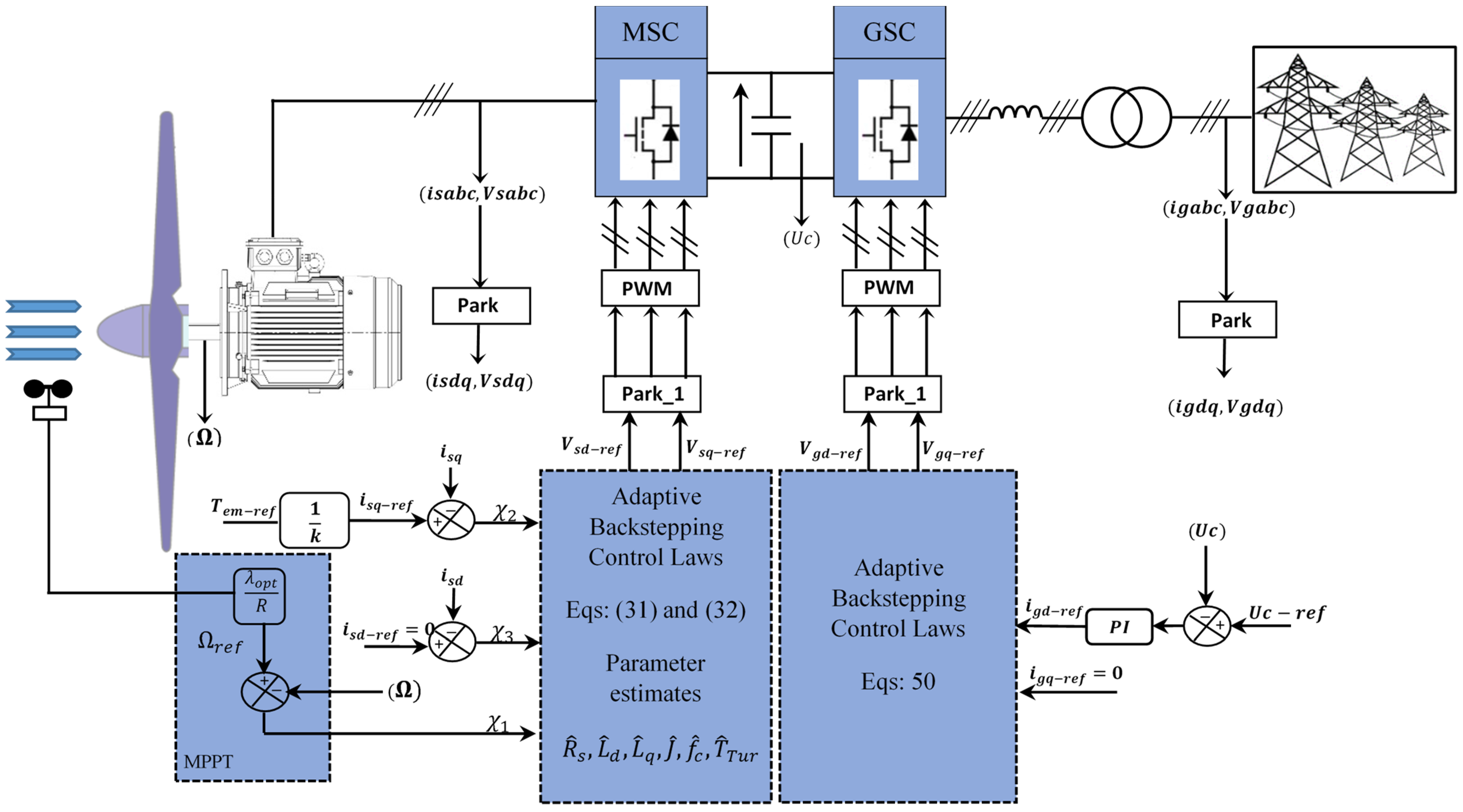
3.1.5. Control of the Grid-Side Converter

The inverter plays a crucial role as a static converter within the conversion chain, simplifying the management of the energy flow injected into the electrical grid. Control of the grid-side inverter primarily focuses on two essential parameters [31]: regulating the intermediate bus voltage and achieving a unity power factor.
The dynamics of grid currents and the transferred power are depicted within the context of a rotating reference frame, as outlined below:
d i g d d t = 1 L f V f d V g d R f . i g d + ω g . L f . i g q d i g q d t = 1 L f V f q V g q R f . i g q ω g . L f . i g d ω e . Ψ f
P g = 3 2 V g d . i g d + V g q . i g q Q g = 3 2 V g q . i g d V g d . i g q
As is evident from Equations (43) and (44), it becomes evident that electrical powers exhibit a direct proportionality with the network’s current components. This observation paves the way for the design of backstepping control, structured upon the ensuing steps:
The disparities in the magnitudes of grid currents are precisely delineated through the subsequent expressions:
ξ g q = i g q _ r e f i g q ξ g d = i g d _ r e f i g d
The dynamics inherent in these errors, in accordance with Equation (45), can be derived as follows:
ξ g q = i g q _ r e f i g q ξ g d = i g d _ r e f i g d
The Lyapunov candidate function is represented in the subsequent format:
γ g = 1 2 ξ g d 2 + 1 2 ξ g q 2
Its time derivative is given by
γ g = ξ g d . ξ g d + ξ g q . ξ g q
By inserting the current dynamics outlined in the system of Equation (43) into the expression of Equation (48), the resultant expression becomes
γ g = k g 1 . ξ g d 2 k g 2 . ξ g q 2 + ξ g d L f V f d V g d R f . i g d + ω g . L f . i g q + k g 1 . L f . ξ g d + ξ g q L f V f q V g q R f . i g q ω g . L f . i g d ω e . Ψ f + k g 2 . L f . ξ g q
For the purpose of establishing system stability in energy injection into the network, it is imperative to adopt positive values for kg1 and kg2. Additionally, the reference voltages administered to the grid-side converter (GSC) should be determined in alignment with the system described by Equation (50):
V f d _ r e f = V g d + R f . i g d L f . ω g . i g q L f . k g 1 . ξ g d V g q _ r e f = V g q + R f . i g q + L f . ω g . i g d L f . k g 2 . ξ g q
The determination of reference values for the direct and quadrature components of the grid current is guided by
igd_ref = 0: This choice ensures the elimination of reactive power, thereby facilitating the transmission of electrical power to the grid with the power factor of unity.
igq_ref: The DC bus voltage regulation is pursued to enable the management of the active power transfer to the electrical grid.
Illustrated in Figure 1 is the layout of the adaptive nonlinear backstepping control framework for PMSG. Within this diagram, Vsd_ref and Vsq_ref denote the target voltage references directed towards the static converter on the machine side. Furthermore, Vgd_ref and Vgq_ref signify the reference voltages employed for the grid static converter.
The values of the current and rotational speed errors are clearly illustrated and mentioned in the text through Equations (11) and (18), while the estimated values of the various parameters are indicated in the text using Equations (24)–(26).

4. Performance Test Using Matlab–Simulink

4.1. Performance Test

The efficacy of the adaptive backstepping control technique in the context of wind power conversion utilizing a PMSG was substantiated through numerical simulations carried out within the Matlab/Simulink environment. Appendix A furnishes the specific parameters pertaining to the wind system, encompassing both the turbine and PMSG components. A comprehensive array of tests was executed to assess and contrast the performance of the regulation between the conventional proportional–integral (PI) controllers and the innovative adaptive backstepping control approach.
The comparative evaluation encompasses a spectrum of assessments, including resilience against perturbations, accuracy in tracking set-points and susceptibility to external disturbances.

4.2. Discussion of Results

Based on the outcomes gleaned from the wind-induced step test, a discernible trend emerges in the context of electromagnetic torque, power dynamics and rotational speed adjustments. This test scenario, illustrated in Figure 2a, entails abrupt changes occurring at t = 2 s, t = 4 s, t = 6 s and t = 8 s. These fluctuations serve to test the system’s resilience when confronted with sudden external disturbances.
The mechanical rotational speed exhibits optimal adherence to the reference value, as showcased in Figure 2b, demonstrating the minimal response time to align with the specified speed. The adaptive control methodology effectively curtails the static error, markedly outperforming the traditional PI regulation, as depicted in the same figure.
Figure 2c,d portray the waveforms of the direct and quadrature stator currents, isd and isq, respectively. These results unveil a synchronization of currents with their designated set-points, characterized by a response time congruent with the system’s dynamics. Additionally, Figure 2e captures the three-phase currents generated by the stator windings. In the magnified view within Figure 2e, the waveforms exhibit a commendable level of quality. Notably, the frequency of these currents maintains a proportional relationship with the mechanical rotational speed. This underscores the necessity of integrating static converters between the PMSG and the grid in variable speed wind turbine technology. This integration serves to precisely adjust the quantity of electricity transmitted to the grid.
Figure 2f reveals the presentation of three-phase currents injected into the electrical grid. Evidently, the quality of these currents surpasses that of the stator currents. The waveform’s periodicity of 20 ms harmoniously aligns with a frequency of 50 Hz, sufficiently meeting the requirements of the electrical network, as magnified within Figure 2f.
Illustrated in Figure 2g are the phase-to-phase voltages characterizing the three-phase stator windings. The configuration of the voltage curves directly stems from the switching of electronic components within the machine-side converter. The figure’s close-up view demonstrates a phase-to-phase stator voltage boasting an amplitude of 5000 V.
The electric current injected into the grid is an outcome of the active power generation. The waveform of this current adheres remarkably well to network code prerequisites concerning frequency and quality, as evident in both Figure 2f,h. The alignment of the current with the mains voltage remains consistently maintained, as indicated by the concurrent current/voltage graph in Figure 2h. A phase shift nearly approaching zero is discernible, contributing to an operation characterized by a power factor approaching unity.
Noteworthy is the seamless synchronization between electrical active power and the evolution of mechanical drive power, exhibiting minimal ripple. This attribute remains exceptionally acceptable within the adaptive backstepping control framework, especially when considering the generator’s substantial power rating, approximately 1500 KW, and its pronounced inertia. As displayed in Figure 2i, this power evolution demonstrates a remarkable continuation in steady-state, underscored by an improved response time in dynamic conditions, quantified at 10 ms. The ripples attributed to the adaptive control remain notably subdued compared to conventional control methodologies, as is visually represented in the same figure.
The system depicted in Figure 1 is simulated with the objective of delivering zero reactive power, thereby harnessing clean power generation and achieving the unity power factor. However, as depicted in Figure 2m, the power factor, though typically near unity, demonstrates fluctuations that correlate with variations in the active power output. Such fluctuations in reactive power regulation are expected when active power levels undergo changes, as depicted in the graph of Figure 2j. Even a minor variation of ∆Qgen = 15Kvar, observed in the zoomed graph of Figure 2j, induces a slight alteration in the power factor for both control types, although adaptive control showcases a slight enhancement.
Figure 2k offers insight into the behavior of the intermediate DC bus situated between the two static converters (rectifier and inverter). This intermediate system effectively maintains a constant voltage, UDC, at the terminals of the two converters. While there exists a variation in the intermediate DC voltage attributed to fluctuations in active power generation, the deviation of ∆UDC = 4V, observed in the zoomed graph of Figure 2k, remains within acceptable limits, constituting a mere 0.08% deviation with respect to the nominal voltage value. The minor initial overshoot discernible in the same figure’s zoomed view, not exceeding 0.26%, alongside the estimated response time of approximately 15 ms, affirms the exceptional performance exhibited by the DC bus voltage regulator.
The electromagnetic torque, depicted in Figure 2l, tracks its reference value with precision, bearing a comparable absolute value to the generated active power. In terms of speed and static error management, adaptive control demonstrates commendable results when juxtaposed with conventional control methodologies, as evidenced by the zoomed view in Figure 2l.
To offer a more comprehensive perspective on the quality of the energy produced and supplied to the grid, a spectral analysis of the harmonic content within the injected current is conducted. Figure 2n,o present the outcomes of this analysis for both classic and adaptive control approaches, respectively. The total harmonic distortion (THD) of the current is measured at 2.41% for classic vector control and 0.38% for adaptive backstepping control, encompassing two operational cycles and up to a maximum frequency of 1000 Hz. The THD achieved through the adaptive control method remains notably competitive and aligns completely with the “IEEE-519” standard, which stipulates a THD requirement of less than 5% for grid-injected currents [11].
A comparative analysis was conducted between the two control algorithms within the context of this performance test simulation for the wind system powered by a PMSG. Table 1 provides an overview of the key facets encompassing this comparison.
A subsequent comparative investigation contrasting the outcomes yielded by the proposed control algorithm with those of other studies is detailed in the subsequent table. Table 2 additionally offers a comprehensive breakdown of the technical specifications, along with the distinct advantages and disadvantages associated with each control technique.
In order to make a valid comparison between several studies, it is necessary to have the same simulation conditions and the same parametric quantities. However, achieving this is not always feasible, and it would be a challenging endeavor. Nevertheless, by conducting an indicative comparison based on a few well-defined parameters, we can extract the main characteristics for each control algorithm and discern the primary advantages of each study.
Table 2 serves as a comprehensive juxtaposition of control algorithm outcomes from a selection of published studies involving two types of wind generators. Upon scrutinizing the displayed outcomes, a conspicuous trend emerges: the proposed control algorithm devised for regulating the wind energy conversion system (WECS) based on the 1.5 MW PMSG consistently yields superior results in comparison to various other control strategies. This ascendancy is notably evident across multiple fronts, including robustness, speed, and energy quality. The system’s elevated power factor, coupled with a remarkably low total harmonic distortion (THD) that remains below 0.38%, unequivocally validates the efficacy of the chosen approach. This reaffirms that the adaptive backstepping control methodology stands out as a premier contender in the realm of the wind energy conversion system (WECS) control.

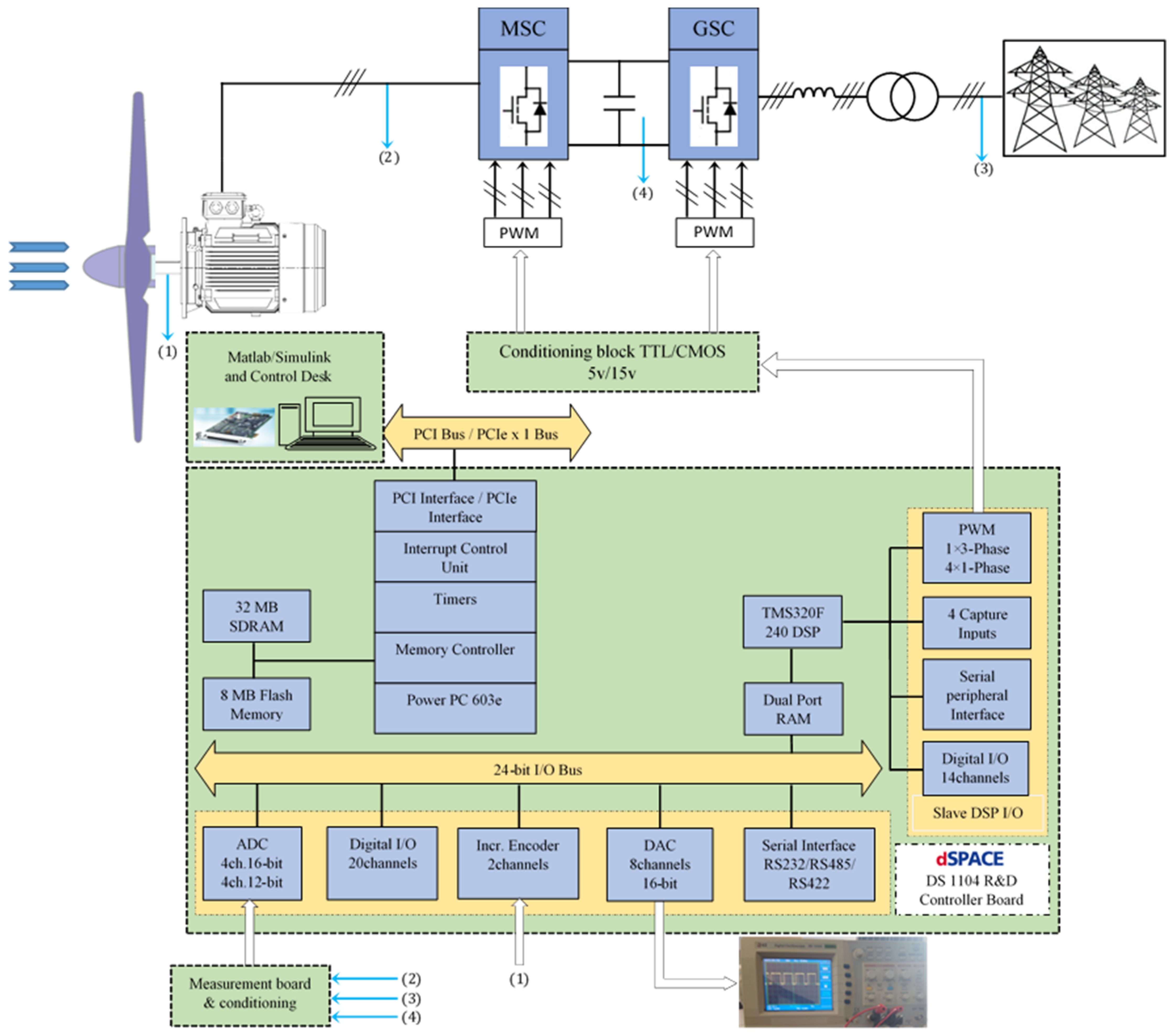
5. Experimental Validation

5.1. Description of Experimental Platform

The results of this approach were obtained using the dSPACE 1104 board in conjunction with Matlab–Simulink for processor-in-the-loop (PIL), a commonly employed method for real-time validation of embedded control systems. Subsequently, the key steps for this experimental validation are as follows:
Modeling in Matlab–Simulink: Initially, the control system, including the model of the wind turbine’s electrical system, as well as the adaptive backstepping controller, was modeled within the Matlab–Simulink environment. This modeling encompasses all the equations and components necessary to accurately represent the system.
Real-time Simulation: In the simulation stage, the authors executed the Simulink model in real-time mode. This means that the Simulink model operates with strict temporal synchronization, simulating the real-time behavior of the wind turbine’s electrical system.
Interface with the dSPACE 1104 board: The dSPACE 1104 board was utilized to interface the real-time Simulink model with the physical hardware. The dSPACE board is capable of reading signals generated by the Simulink model and converting them into physical signals that can be used to control the real system, such as controllers or for display on an oscilloscope.
Real-time Execution: The real-time Simulink model was executed on the dSPACE 1104 board, which acts as a real-time processor. This real-time execution enables the testing and validation of the adaptive backstepping controller under conditions closely resembling reality, with signals observed on an oscilloscope.
Data Collection and Analysis: During real-time execution, the authors collected data on the system’s behavior, including control signals and some physical signals. These data were subsequently analyzed to assess the performance of the adaptive backstepping controller and to compare the results with the research objectives.
The experimental platform was established using the dSPACE DS1104 prototyping platform, which encompasses the following components [36]:
DSPACE 1104 kit integrated into a computer.
DS1104 board connection panel.
Host PC equipped with the Matlab/Simulink environment and Control-Desk 7.6 software.
Voltage level adaptation probe.
Oscilloscope for visualizing various analog signals.
To validate and test the control algorithms, a series of essential steps are considered necessary. In this current study, validation through a real-time simulation was implemented to demonstrate the high performance and confirm the algorithm’s effectiveness in a real installation scenario.
The procedure encompasses the subsequent stages:
Developing the control system via the Simulink modeling tool.
Conducting simulations to generate a range of control results.
Transferring the program as C code to dSPACE using the Real-Time Workbench (RTW) utility.
Executing the comprehensive model in real-time via the DS1104 R&D board.

5.2. dSPACE 1104 Digital Processing System

The processor board, manufactured by the German company dSPACE, is outfitted with an MPC8240 main processor operating at a clock frequency of 250 MHz [37]. Additionally, a complementary software known as “Control-Desk” facilitates the construction of a graphical interface, streamlining real-time visualization of diverse parameters.
The interlinkage between the dSPACE board and the wind energy conversion system, centered on the PMSG, is succinctly portrayed in Figure 3.

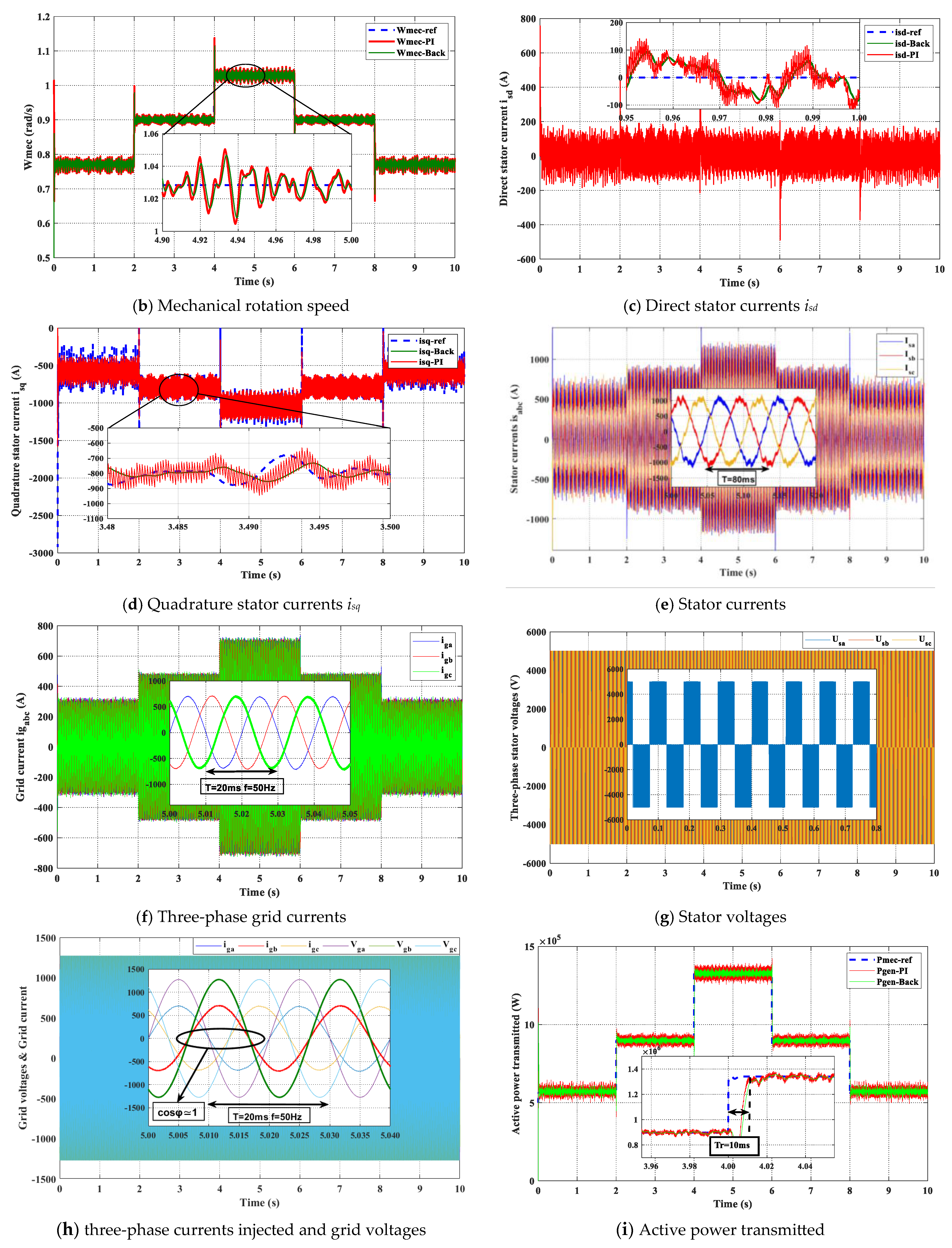
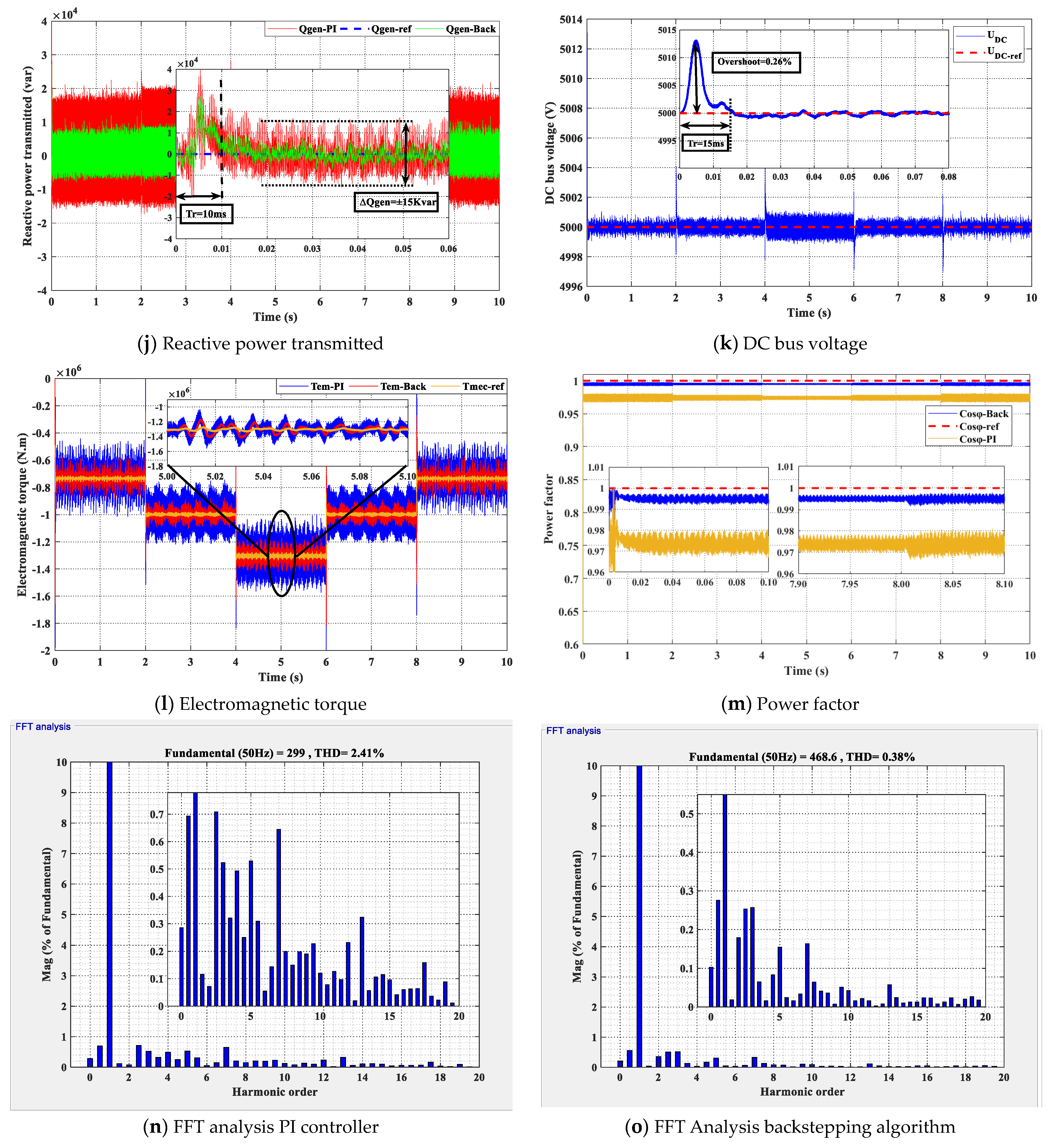
5.3. Results of Implementing the Adaptive Backstepping Control

Figure 3 presents the overall block diagram of the wind system controlled by the adaptive control algorithm, managed by the dSPACE prototyping board. The control signals regulate both converters (rectifier/inverter) simultaneously. Table 3 presents the parameters utilized for this real-time simulation.
In order to substantiate the efficacy of the proposed adaptive control algorithm through real-time simulation, two comprehensive tests are slated for execution. The primary test is designed to underscore the control’s robustness amidst a wind profile characterized by step changes. The subsequent test is tailored to spotlight the control’s adeptness in maintaining tracking accuracy and overall efficiency amid the presence of erratic and extensively variable wind conditions. The execution of these assessments is facilitated by the dSPACE DS1104 board and the Control-Desk development tool, adept at capturing the diverse array of signals of interest.

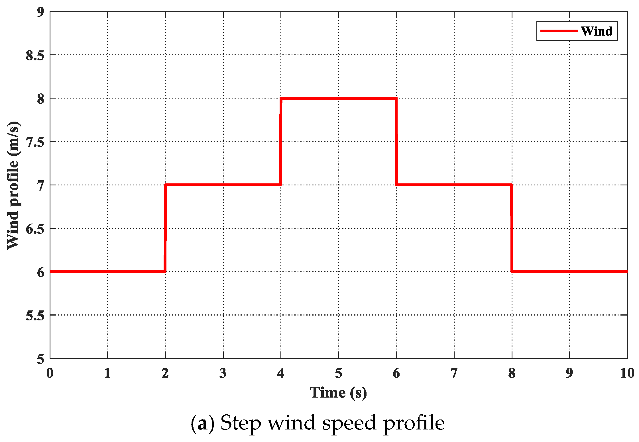
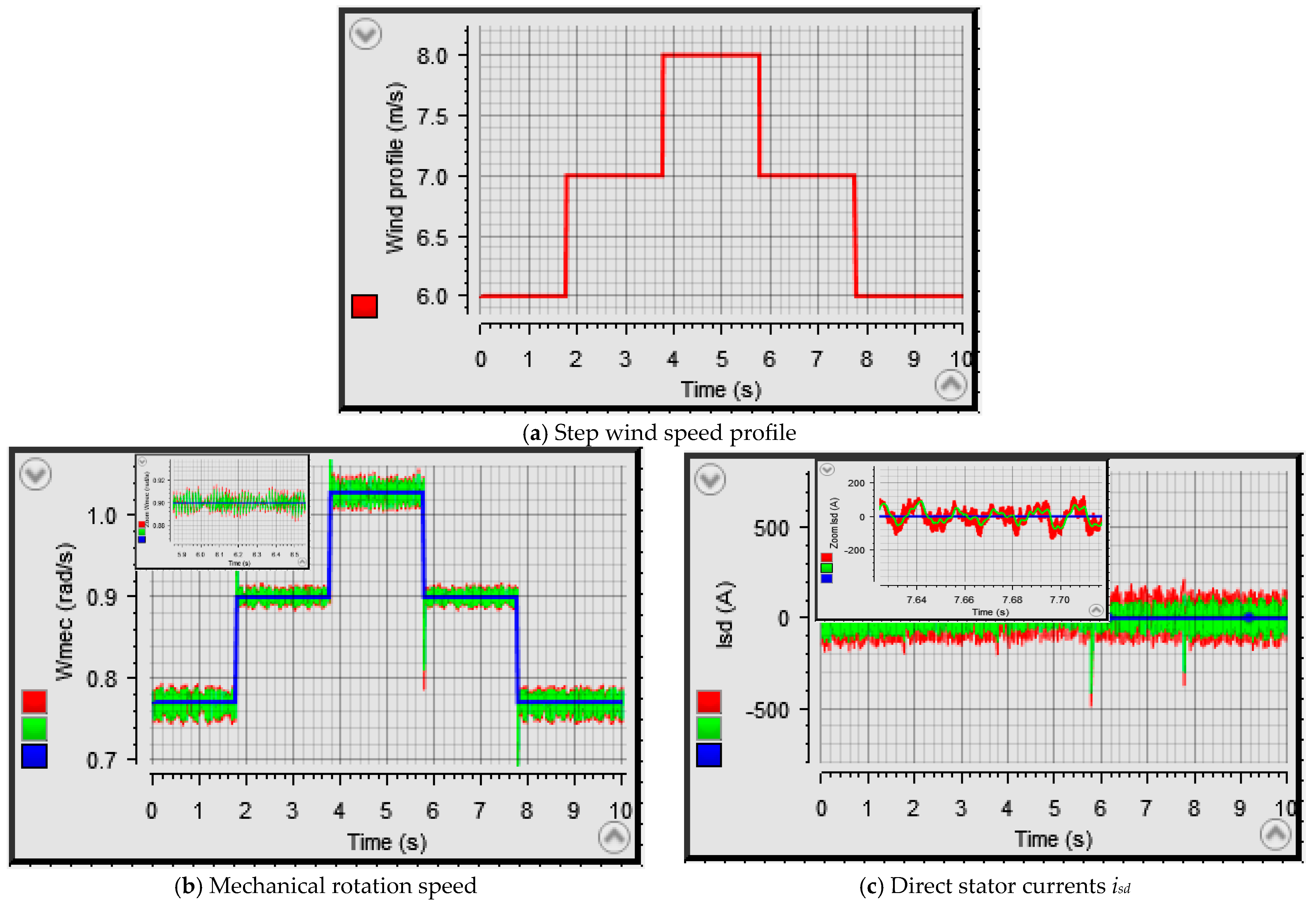
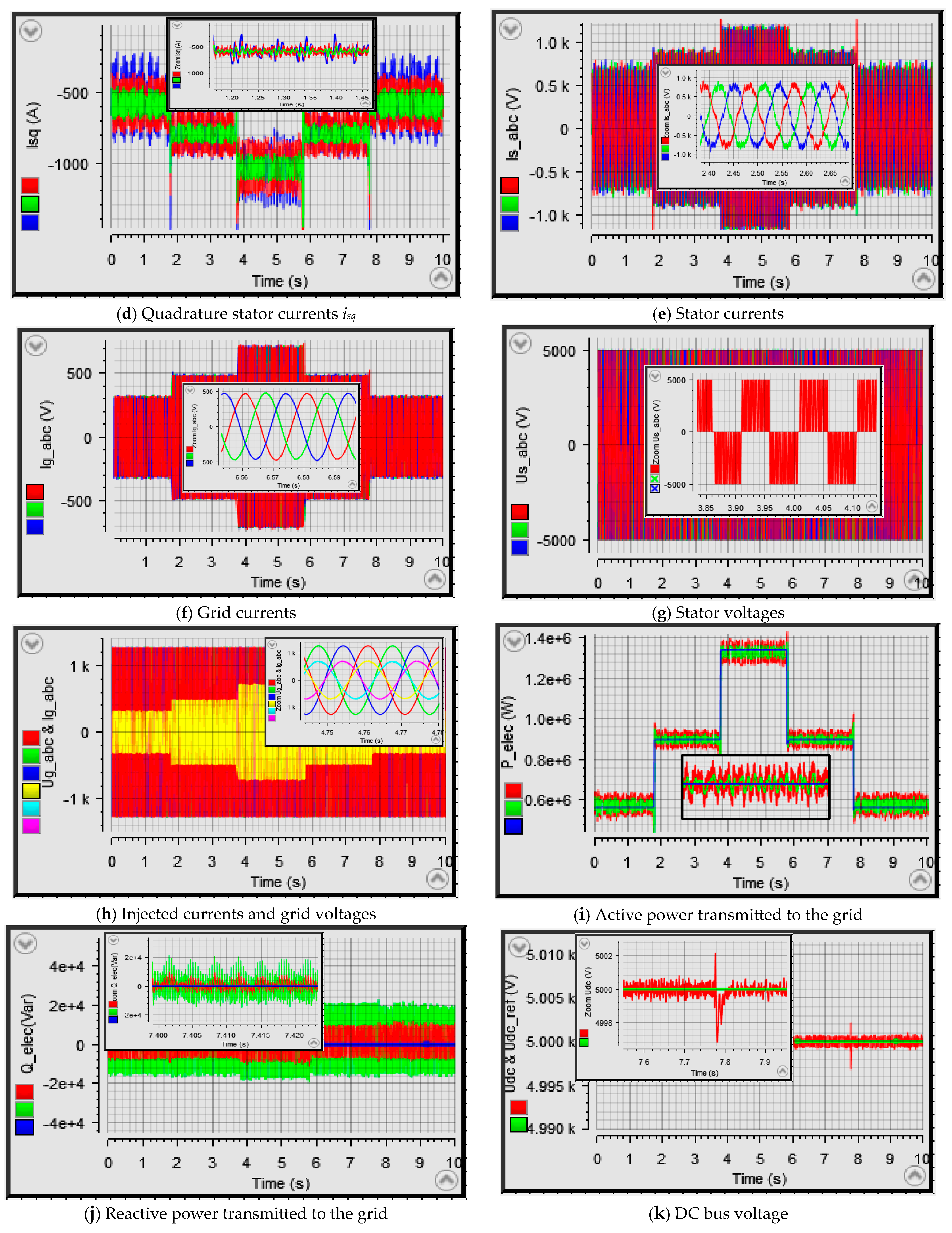
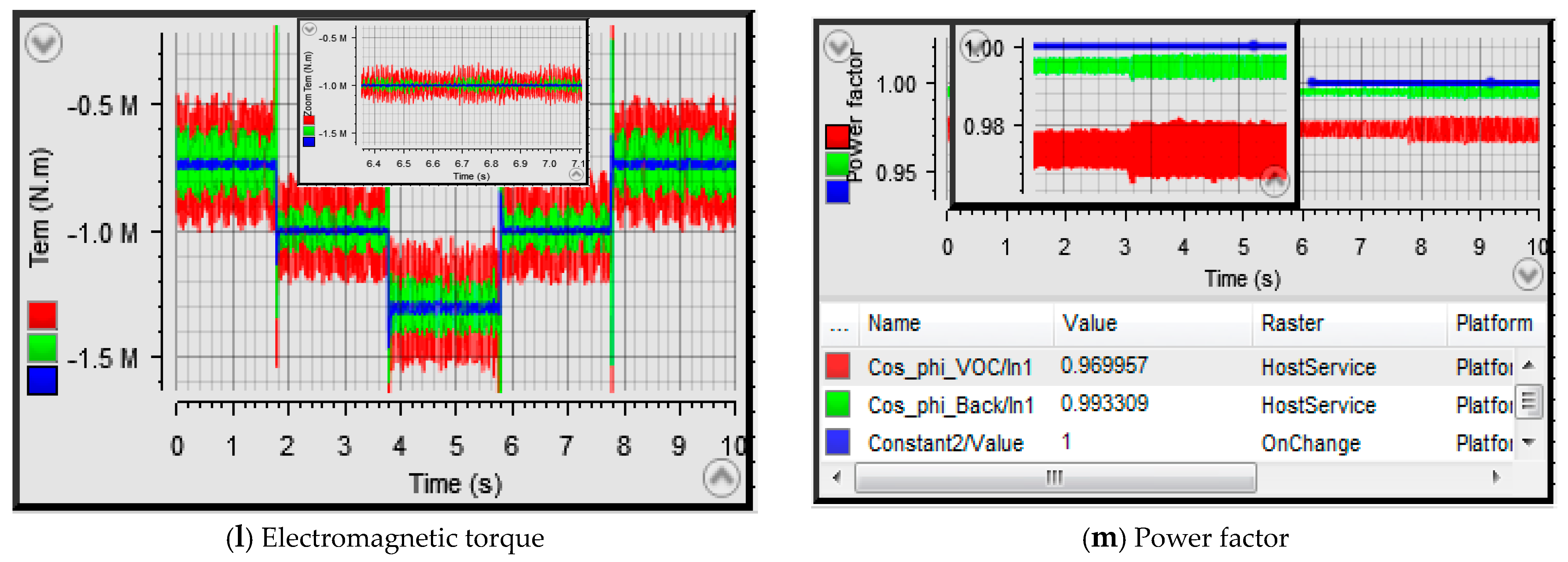
5.3.1. Performance Test for Wind Steps

The first test involves the presence of wind variations in steps. The changes occur every 2 s, aiming to assess the algorithm’s performance in response to sudden wind shifts. The average wind speed is approximately 7 m/s. For further details about the turbine model and PMSG parameters, please refer to Table A1 in Appendix A. The outcomes of this test are summarized below.

5.3.2. Set-Point Tracking Test in Fluctuating Wind

The subsequent evaluation involves a second test conducted under the influence of fluctuating and exceedingly variable wind conditions, aimed at assessing tracking performance. Throughout this test, a consistent sampling frequency of fe = 10 KHz is upheld. A comprehensive overview of the diverse graphical representations obtained during this evaluation is succinctly depicted in Figure 4.

5.3.3. Discussion of Experimental Results

Analyzing the outcomes of the initial test characterized by a stepwise wind profile, the wind’s oscillations occurring every 2 s within a 10 s span, as visualized in Figure 4a showcasing the chosen wind profile, reveal a distinct synchronization among the mechanical speed, stator currents and generated active power. Evidently, as illustrated in Figure 4b–d,i, these results underscore the convergence of these dynamics. Remarkably, when scrutinizing the array of graphs, the adaptive control algorithm consistently manifests elevated performance and noteworthy quality outcomes, demonstrating a definitive edge over the conventional control methods.
Figure 4c,d delineate the regulation of the direct and quadrature stator currents, respectively. These graphical representations affirm that the backstepping control strategy achieves precise tracking with minimal oscillations. While the three-phase stator currents presented in Figure 4e exhibit a pseudo-sinusoidal pattern, their agile response to transient shifts is evident. Notably, the switching of electronic components within the static converter contributes to a pronounced harmonic content. Additionally, the depicted waveform’s period aligns with an approximate duration of 100 ms.
Figure 4f visually depicts the injected current waveforms within the electrical grid. A discernible sinusoidal nature characterizes these currents compared to those generated by the synchronous generator. Notably, the zoomed-in section of the same figure underscores the rigorous adherence to the grid’s periodicity and frequency requisites, maintaining a 20ms period congruent with the network’s 50 Hz frequency.
The portrayal of three-phase stator voltages takes center stage in Figure 4g. These voltage profiles assume a rectangular shape due to the electronic switch’s switching in the machine-side converter. The zoomed-in segment of the same figure distinctly showcases a phase-to-phase voltage reading of 5000 V.
As clearly depicted in the combined graph of grid voltages and injected currents in Figure 4h, a coherent temporal alignment between the three-phase voltages and currents is observable, resulting in a phase shift of zero and thereby ensuring operation with a unity power factor. This synchronization is maintained impeccably, as indicated by the consistent 50 Hz frequency displayed in the zoomed-in section of Figure 4h.
Figure 4i offers insight into the injected active power within the power grid. With the wind speed in flux, the mechanical drive power undergoes near-instantaneous changes, consequently impacting the active power delivered to the grid. Remarkably, this synchronization between the speed and Figure 4i remains consistently upheld. Noteworthy adeptness in tracking the reactive power is evidenced by Figure 4j, wherein the reactive power closely follows its null reference while maintaining a low value, evaluated at 20 Kvar. This precise tracking culminates in the injection of predominantly active power into the electrical grid. The relatively modest level of reactive power, relative to the active power supplied to the grid, contributes to a power factor nearing unity. Figure 4m charts the behavior of the power factor during a step change in wind conditions, demonstrating a remarkable value of (cosφ > 0.99) for the backstepping control.
The simulation outcomes unveil the regulatory impact on the DC bus voltage, as is evident in Figure 4i. The voltage at the inverter’s input closely follows the reference value set at 5000 V. The regulator’s effectiveness is discernible from the swift signal response time and minimal overshooting, confined within +/−2 V, as highlighted in the zoomed section of Figure 4i. While electromagnetic torque still exhibits notable ripples, the adaptive control strategy showcases an improved performance in electromagnetic torque, as visualized in Figure 4j.
Turning to the outcomes of the second test, which involves fluctuating wind conditions, as illustrated in Figure 5a, it is unmistakable that all variables align closely with their reference values. Particularly noteworthy is the mechanical rotation speed’s precision in tracking its reference value, a trait prominently pronounced in the regulation achieved through the adaptive control, as evidenced in Figure 5b.
In another scenario, the distinct patterns of the currents generated by the stator windings of the synchronous generator adopt a pseudo-sinusoidal shape. These patterns exhibit varying periods that correspond to fluctuations in wind speed, as depicted in Figure 5c. The approximate period of the three-phase stator currents measures around 100 ms. In contrast, the shapes of the three-phase currents injected into the grid adopt a more sinusoidal form, conforming to the requirements of the IEEE-519 standard. Figure 5d illustrates the waveforms of the currents injected into the electrical network, with a focused section underscoring the high-quality waveform and confirming a consistent period of 20 ms.
Similarly, during this second test, the characteristic rectangular shape of the phase-to-phase voltages at the stator winding terminals, set at 5000 V, remains conspicuous, as showcased in Figure 5e. Furthermore, Figure 5f presents the temporally aligned shapes of the three currents injected into the grid alongside their corresponding grid voltages. The minimal phase discrepancy between the current and voltage waveforms contributes to a power factor approaching unity. This phenomenon is even more pronounced in Figure 5k, which illustrates the measured power factors for both the vector control and backstepping algorithms. As is evident in Figure 5k, the adaptive control attains a power factor of cosφ ≃ 0.995, surpassing the vector control’s cosφ ≃ 0.973.
The precision of active power adherence to its mechanical reference is effectively showcased in Figure 5g. A closer examination of this power behavior, displayed within the same figure, reaffirms the adaptive control’s capability in maintaining precise active power regulation. In contrast, the reactive power remains nearly perfectly regulated towards its zero reference. The marginal variation of reactive power within approximately ± 20Kvar, as observed in Figure 5h for a 1500 KW synchronous generator, consistently upholds a high power factor. The adaptive control approach consistently outperforms in terms of regulation finesse and efficiency, a trend mirrored in the reactive power regulation as well.
The regulation of the DC bus voltage, a pivotal factor in determining the reference current needed for calculating transmitted active power to the grid, is visualized in Figure 5i. The efficacy of this regulation becomes evident when examining the zoomed-in segment of Figure 5i, where a mere ± 1V voltage variation is observed in comparison to the reference voltage of 5000 V.

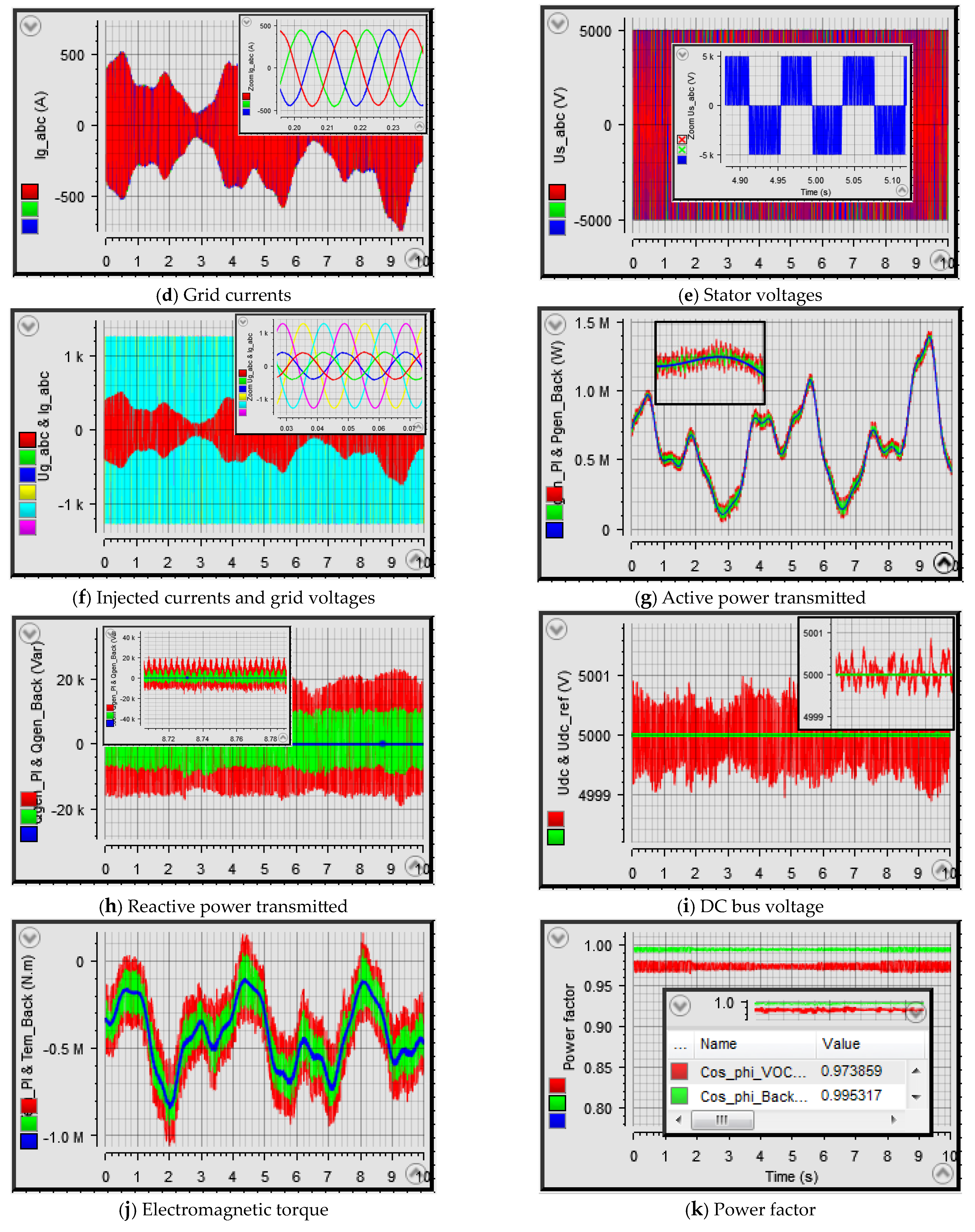
5.3.4. Visualization of Analog Signals

The sampling of analog signals is greatly facilitated by the connection panel of the dSPACE DS1104 card. This panel allows the connection of up to eight output analog signal channels equipped with digital-to-analog converters (DAC). In order to convincingly demonstrate the card’s compatibility with external components, we measured and displayed the switching signals, as well as certain signals involving the injection of voltage and phase current, using a digital oscilloscope, as illustrated in Figure 6.
The objective of this figure is to provide a visual representation of the experiment, highlighting the equipment used within the context of the processor-in-the-loop (PIL) to validate the proposed control algorithm in this work. It should be noted that Figure 6 features a reference digital oscilloscope: the “EZ, Digital Oscilloscope DS 1250C.” This instrument enabled the visualization of various signals while adjusting the adaptive gains of the RTI Toolbox in Matlab/Simulink for a more in-depth analysis.

6. Conclusions

In this study, an adaptive nonlinear algorithm based on the Lyapunov theory for the control of wind energy conversion systems is introduced. The results obtained highlight several significant advantages in terms of robustness and precision when dealing with various regulatory challenges.
The algorithm was initially simulated in the Matlab/Simulink environment and subsequently validated through experimental implementation on the dSPACE DS1104 prototyping platform. The results of these tests, which included variations in external wind conditions, clearly demonstrate the effectiveness of the adaptive backstepping control algorithm. It has proven capable of reducing overshoots, mitigating fluctuations, and improving response times across different parameter sets.
The notable improvements to the wind energy conversion system, based on permanent magnet synchronous generators (PMSG), can be briefly summarized as follows:
An exceptionally low total harmonic distortion (THD) of the injected grid currents, approximately 0.38%.
A significant reduction in the overshooting of electrical quantities.
Decreased magnitude ripples compared to the classic vector controller.
The conclusive validation of the simulation results in Matlab/Simulink compared to the experimental data, facilitated by the ControlDesk tool.
The ensuring of the operation with a unity power factor, achieved through the effective regulation of both active and reactive power injected into the electrical grid.
Ultimately, the demonstration of the robustness of adaptive control in terms of tracking and regulation across various parameter sets.
To further advance this research, the authors and members of the laboratory team have identified the following future prospects:
The development of a comprehensive test bench that integrates the PMSG, power converters, wind emulator and the dSPACE DS1104 prototyping board to validate the adaptive backstepping control algorithm.
The development of an advanced simulation model that incorporates the aforementioned variables, particularly during three-phase faults and scenarios of asymmetric faults, in accordance with the current electrical grid codes.

Author Contributions

Conceptualization, Y.E.M., H.S., B.B. and S.M. (Saad Motahhir); methodology, Y.E.M.; software, Y.E.M. and H.S.; validation, Y.E.M. and B.B.; formal analysis, Y.E.M.; investigation, Y.E.M., H.S. and B.B; resources. Y.E.M., H.S. and B.B.; data curation. Y.E.M., H.S. and B.B. writing—original draft preparation, Y.E.M., H.S. and B.B.; writing—review and editing, Y.E.M., H.S., B.B.; A.D., S.M. (Saad Motahhir), S.M. (Saleh Mobayen) and A.Z.; visualization, Y.E.M., H.S., B.B.; A.D., S.M. (Saad Motahhir), S.M. (Saleh Mobayen) and A.Z.; supervision, Y.E.M., H.S. and B.B.; project administration, B.B., Y.E.M. and S.M. (Saad Motahhir); funding acquisition, B.B., S.M. (Saleh Mobayen) and A.Z. All authors have read and agreed to the published version of the manuscript.

Funding

The research is partially funded by the Ministry of Science and Higher Education of the Russian Federation as part of the World-class Research Center program: Advanced Digital Technologies (contract N°: 075-15-2022-312 dated 20 April 2022).

Data Availability Statement

The datasets used and/or analyzed during the current study are available from the corresponding author on reasonable request.

Conflicts of Interest

The authors declare no conflict of interest.

Appendix A

Table A1. PMSG and wind turbine parameters.
Generator and Wind Turbine
ParametersSymbolValues
Power generatorPn1.5 MW
Pole numberp72
Stator resistanceRs6.25 mΩ
d axis inductanceLd4.229 mH
q axis inductanceLq4.229 mH
Generator rotor fluxψf11.1464 Wb
Radius of the turbine bladeR50 m
Turbine and generator
Moment
J10,000 N.m
Viscous frictionfc0.015 N.m.s/rad
Specific density of airρ1.22 kg/m3

Nomenclature

VwWind speed (m/s)
Turbine/machine rotational speed (rad/s)
JTurbine/machine total moment of inertia (Nm)
f c Friction forces (N m s/rad)
P a e r Air power (W)
P T u r Turbine power captured (W)
ρ Air density (Kg/m3)
S Turbine rotor surface (m2)
CpPower coefficient (-)
λTip speed ration (-)
βPitch angle (°)
R Turbine blade radius (m)
T e m Generator electromagnetic torque (Nm)
T T u r Turbine torque (Nm)
P g e n Active generator power (W)
Q g e n Reactive generator power (Var)
p Number of pole pairs (-)
V s , d q Direct/quadrature stator voltage (V)
i s , d q Direct/quadrature stator current (A)
R s Stator resistance (Ω)
L s , d q Stator cyclic inductors in the d-q plane (H)
Ψ f Rotor flux amplitude (Wb)
Ψ s , d q Direct/quadrature stator flux amplitude (Wb)
U C DC link voltage (V)
γ i Lyapunov’s candidate function (-)
χ i Variable machine error (-)
ξ g i Variable grid error (-)
k i Positive constant (-)
σ i System parameter (-)
ƛ i Positive adaptation gain (-)
i g , a b c Three-phase current at the inverter output (A)
V g , a b c Three-phase grid voltages (V)
R f Filter resistance (Ω)
L f Filter inductance (H)
P g Active power injected into the grid (W)
Q g Reactive power injected into the grid (Var)
cos φ Power factor (-)
fGrid frequency (Hz)
S i , a b c Inverter arm switching states (-)

References

  1. Ayub, M.W.; Hamza, A.; Aggidis, G.A.; Ma, X. A Review of Power Co-Generation Technologies from Hybrid Offshore Wind and Wave Energy. Energies 2023, 16, 550. [Google Scholar] [CrossRef]
  2. Fu, D.; Kong, L.; Gong, L.; Wang, A.; Jia, H.; Zhao, N. Wind Turbine Load Optimization Control Strategy Based on LIDAR Feed-Forward Control for Primary Frequency Modulation Process with Pitch Angle Reservation. Energies 2023, 16, 510. [Google Scholar] [CrossRef]
  3. El Mourabit, Y.; Derouich, A.; ElGhzizal, A.; El Ouanjli, N.; Zamzoum, O. Nonlinear Backstepping control of variable speed wind turbine based on permanent magnet synchronous generator. In Proceedings of the International Conference on Wireless Technologies, Embedded and Intelligent Systems (WITS), Fez, Morocco, 3–4 April 2019; pp. 1–7. [Google Scholar] [CrossRef]
  4. Bousla, M.; Haddi, A.; El Mourabit, Y.; Sadki, A.; Mouradi, A.; El Kharrim, A. Detection and Prevention of Repetitive Major Faults of a WTG by Analysis of Alarms Through SCADA. In International Conference on Digital Technologies and Applications; Springer: Cham, Switzerland, 2023; pp. 745–752. [Google Scholar]
  5. Tao, S.; Zhao, L.; Liu, Y.; Liao, K. Impedance Network Model of D-PMSG Based Wind Power Generation System Considering Wind Speed Variation for Sub-Synchronous Oscillation Analysis. IEEE Access 2020, 8, 114784–114794. [Google Scholar] [CrossRef]
  6. El Mourabit, Y.; Derouich, A.; Allouhi, A.; El Ghzizal, A.; El Ouanjli, N.; Zamzoumyes, O. Sustainable production of wind energy in the main Morocco’s sites using permanent magnet synchronous generators. Int. Trans. Electr. Energy Syst. 2020, 30, e12390. [Google Scholar] [CrossRef]
  7. Le, X.C.; Duong, M.Q.; Le, K.H. Review of the Modern Maximum Power Tracking Algorithms for Permanent Magnet Synchronous Generator of Wind Power Conversion Systems. Energies 2023, 16, 402. [Google Scholar] [CrossRef]
  8. Salime, H.; Bossoufi, B.; Motahhir, S.; El Mourabit, Y. A novel combined FFOC-DPC control for wind turbine based on the permanent magnet synchronous generator. Energy Rep. 2023, 9, 3204–3221. [Google Scholar] [CrossRef]
  9. Ding, X.; Zhang, Y.; Ye, Z. Current Sensors Offset Fault Online Estimation in Permanent Magnet Synchronous Generator (PMSG) Drives for Offshore Wind Turbines. IEEE Access 2021, 9, 135996–136003. [Google Scholar] [CrossRef]
  10. Zamzoum, O.; Derouich, A.; Motahhir, S.; El Mourabit, Y.; El Ghzizal, A. Performance analysis of a robust adaptive fuzzy logic controller for wind turbine power limitation. J. Clean. Prod. 2020, 265, 121659. [Google Scholar] [CrossRef]
  11. IEEE Std 519-2014 (Revision of IEEE Std 519-1992); IEEE Recommended Practice and Requirements for Harmonic Control in Electric Power Systems. IEEE: New York, NY, USA, 2014; pp. 1–29. [CrossRef]
  12. Ali, M.; Kotb, H.; Aboras, K.M.; Abbasy, N.H. Design of Cascaded PI-Fractional Order PID Controller for Improving the Frequency Response of Hybrid Microgrid System Using Gorilla Troops Optimizer. IEEE Access 2021, 9, 150715–150732. [Google Scholar] [CrossRef]
  13. Errouissi, R.; Al-Durra, A. A Novel PI-Type Sliding Surface for PMSG-Based Wind Turbine with Improved Transient Performance. IEEE Trans. Energy Convers. 2018, 33, 834–844. [Google Scholar] [CrossRef]
  14. Salime, H.; Bossoufi, B.; Zine Laabidine, N.; Saady, I.; Elalami, H.; Majout, B.; ELMourabit, Y. FOC-DPC Hybrid Structure of a Wind Energy Conversion System Based on PMSG. In International Conference on Digital Technologies and Applications; Springer: Cham, Switerland, 2022; pp. 693–702. [Google Scholar] [CrossRef]
  15. El Mourabit, Y.; Derouich, A.; ElGhzizal, A.; Zamzoum, O. Dynamic modeling and control of a wind turbine with MPPT control connected to the grid by using PMSG. In Proceedings of the 2017 International Conference on Advanced Technologies for Signal and Image Processing (ATSIP), Fez, Morocco, 22–24 May 2017; pp. 1–6. [Google Scholar] [CrossRef]
  16. Asgharnia, A.; Shahnazi, R.; Jamali, A. Performance and robustness of optimal fractional fuzzy PID controllers for pitch control of a wind turbine using chaotic optimization algorithms. ISA Trans. 2018, 79, 27–44. [Google Scholar] [CrossRef]
  17. Qais, M.H.; Hasanien, H.M.; Alghuwainem, S. A Grey Wolf Optimizer for Optimum Parameters of Multiple PI Controllers of a Grid-Connected PMSG Driven by Variable Speed Wind Turbine. IEEE Access 2018, 6, 44120–44128. [Google Scholar] [CrossRef]
  18. Zhang, Z.; Zhao, Y.; Qiao, W.; Qu, L. A Discrete-Time Direct Torque Control for Direct-Drive PMSG-Based Wind Energy Conversion Systems. IEEE Trans. Ind. Appl. 2015, 51, 3504–3514. [Google Scholar] [CrossRef]
  19. Zhang, Z.; Li, Z.; Kazmierkowski, M.P.; Rodríguez, J.; Kennel, R. Robust Predictive Control of Three-Level NPC Back-to-Back Power Converter PMSG Wind Turbine Systems with Revised Predictions. IEEE Trans. Power Electron. 2018, 33, 9588–9598. [Google Scholar] [CrossRef]
  20. AOsman, M.; Alsokhiry, F. Sliding Mode Control for Grid Integration of Wind Power System Based on Direct Drive PMSG. IEEE Access 2022, 10, 26567–26579. [Google Scholar] [CrossRef]
  21. Yang, B.; Yu, T.; Shu, H.; Zhang, Y.; Chen, J.; Sang, Y.; Jiang, L. Passivity-based sliding-mode control design for optimal power extraction of a PMSG based variable speed wind turbine. Renew. Energy 2018, 119, 577–589. [Google Scholar] [CrossRef]
  22. Yang, B.; Zhong, L.; Yu, T.T.; Shu, H.; Cao, P.; An, N.; Sang, Y.; Jiang, L. PCSMC design of permanent magnetic synchronous generator for maximum power point tracking. IET Gener. Transm. Distrib. 2019, 13, 3115–3126. [Google Scholar] [CrossRef]
  23. Jafarian, M.; Ranjbar, A.M. Fuzzy modeling techniques and artificial neural networks to estimate annual energy output of a wind turbine. Renew. Energy 2010, 35, 2008–2014. [Google Scholar] [CrossRef]
  24. Calderaro, V.; Galdi, V.; Piccolo, A.; Siano, P. A fuzzy controller for maximum energy extraction from variable speed wind power generation systems. Electr. Power Syst. Res. 2008, 78, 1109–1118. [Google Scholar] [CrossRef]
  25. Pourebrahim, R.; Shotorbani, A.M.; Márquez, F.P.G.; Tohidi, S.; Mohammadi-Ivatloo, B. Robust Control of a PMSG-Based Wind Turbine Generator Using Lyapunov Function. Energies 2021, 14, 1712. [Google Scholar] [CrossRef]
  26. Morse, A.S.; Feurer, A. Adaptive control of single-input-single-ouput linear systems. IEEE Trans. Autom. Control 1978, 23, 557–569. [Google Scholar]
  27. Sussmann, H.J.; Kokotovic, V. A positive real condition for global stabilization of nonlinear systems. Syst. Control Lett. 1989, 13, 125–133. [Google Scholar]
  28. Tsinias, J. Sufficient lyapunov-like conditions for stabilization. Math. Control Signal Syst. 1989, 2, 343–357. [Google Scholar] [CrossRef]
  29. KanellaKopoulos, I.; Kokotovic, P.V.; Morse, A.S. Systematic Designof Adaptive Controllers for Feedback Linearizable Systems. IEEE Trans. Autom. Control 1991, 36, 1241–1253. [Google Scholar] [CrossRef]
  30. Freeman, R.A.; Kokotovic, P.V. A New Lyapunov Function for the Backstepping Design of ’Softer’ Robust Nonlinear Control Laws. In Proceedings of the Nonlinear Control System Design Symposium, Bordeaux, France, 24–26 June 1992. Technical Report no. CCEC-92-0520. [Google Scholar]
  31. El Mourabit, Y.; Derouich, A.; El Ghzizal, A.; El Ouanjli, N.; Zamzoum, O. Nonlinear backstepping control for PMSG wind turbine used on the real wind profile of the Dakhla-Morocco city. Int. Trans. Electr. Energy Syst. 2020, 30, e12297. [Google Scholar] [CrossRef]
  32. Beddar, A.; Bouzekri, H.; Babes, B.; Afghoul, H. Experimental enhancement of fuzzy fractional order PI + I controller of grid connected variable speed wind energy conversion system. Energy Convers. Manag. 2016, 123, 569–580. [Google Scholar] [CrossRef]
  33. Chakib, M.; Essadki, A.; Nasser, T. A comparative study of PI, RST and ADRC control strategies of a doubly fed induction generator based wind energy conversion system. Int. J. Renew. Energy Res. 2018, 8, 964–973. [Google Scholar]
  34. Ihedrane, Y.; Bekkali, C.; Ghamrasni, M.; Mensou, S.; Bossoufi, B. Improved wind system using non-linear power control. Indones. J. Electr. Eng. Comput. Sci. 2019, 14, 1148–1158. [Google Scholar] [CrossRef]
  35. Benamor, A.; Benchouia, M.T.; Srairi, K.; Benbouzid, M.E.H. A new rooted tree optimization algorithm for indirect power control of wind turbine based on a doubly-fed induction generator. ISA Trans. 2019, 88, 296–306. [Google Scholar] [CrossRef]
  36. Mourabit, Y.E.L.; Derouich, A.; Ghzizal, A.E.L.; Bouchnaif, J.; Ouanjli, N.E.L.; Zamzoum, O.; Mezioui, K.; Bossoufi, B. Implementation and validation of backstepping control for PMSG wind turbine using dSPACE controller board. Energy Rep. 2019, 5, 807–821. [Google Scholar] [CrossRef]
  37. Card Presentation «DSPACE DS 1104». Available online: www.dspace.com (accessed on 21 June 2023).
Figure 1. Block Diagram of Adaptive Backstepping Control.
Energies 16 07481 g001
Figure 2. Performance Testing for the Adaptive Backstepping Control.
Energies 16 07481 g002aEnergies 16 07481 g002bEnergies 16 07481 g002c
Figure 3. Connection diagram of dSPACE with the WECS.
Energies 16 07481 g003
Figure 4. Performance test for wind in step.
Energies 16 07481 g004aEnergies 16 07481 g004bEnergies 16 07481 g004c
Figure 5. Set-point tracking test in fluctuating wind.
Energies 16 07481 g005aEnergies 16 07481 g005b
Figure 6. Digital Oscilloscope Integration with dSPACE Controller Board.
Energies 16 07481 g006
Table 1. Comparative analysis between FOC and backstepping adaptive controllers.
Controller TypeFOCBackstepping
Coordinate transformationRequiredRequired
Torque rippleMediumLow
Currents rippleMediumLow
Reference trackingMediumBetter
THD (%)2.410.38
Facility of implementationSimpleComplex
Algorithm complexityLowComplex
Table 2. Performance comparison.
Publication Paper[32][32][33][34][35]Proposed Algorithm
Technic methods(FOPI)(FFOPI+I)(ADRC)(SMC)RTO-PI(ABC)
Generator usedPMSGPMSGDFIG
(1.5 MW)
DFIGDFIG
(4 KW)
PMSG (1.5 MW)
Overshoot (%)12421-10.26
THD (%)4.54-3.993.210.38
Response time (ms)--27549-10
Power factor0.9740.994--0.9780.997
Facility of implementationSimpleModerate–simpleModerate–simpleSimpleModerate–highComplex
Algorithm complexityMediumMediumMediumMediumComplexComplex
performanceLowModerate–highLowLowModerate–highHigh
Table 3. Parameters used in simulation.
ParameterValue
DC bus voltage5000 V
DC Bus Capacitor20 mF
Filter resistance0.20 mΩ
Filter inductance10 mH
Sampling frequency10 KHz
Grid frequency50 Hz
Disclaimer/Publisher’s Note: The statements, opinions and data contained in all publications are solely those of the individual author(s) and contributor(s) and not of MDPI and/or the editor(s). MDPI and/or the editor(s) disclaim responsibility for any injury to people or property resulting from any ideas, methods, instructions or products referred to in the content.

