Article

Robust Constant Exponent Coefficient Fixed-Time Control Based on Finite-Time Extended Sliding Mode Observer of Permanent Magnet Synchronous Motors

by
Varin Cholahan
,
Napasool Wongvanich
and
Worapong Tangsrirat
*
School of Engineering, King Mongkut’s Institute of Technology Ladkrabang, Bangkok 10520, Thailand
*
Author to whom correspondence should be addressed.
Energies 2023, 16(21), 7454; https://doi.org/10.3390/en16217454
Submission received: 22 September 2023 / Revised: 30 October 2023 / Accepted: 1 November 2023 / Published: 6 November 2023
(This article belongs to the Section F: Electrical Engineering)

Abstract

:
This paper presents the Robust Constant Exponent Coefficient Fixed-Time Control (CECFSMC), an innovative control technique for precisely regulating the speed of a permanent magnet synchronous motor (PMSM) by utilizing fixed-time stability with constant exponent coefficients to provide not only faster convergence but also in a specific period of time. The effect of chattering is also lessened. To ensure that the designed controller produces the desired performance under bounded disturbances, a finite-time extended sliding-mode observer (ESMO) is also designed to estimate the PMSM velocity while also estimating lumped load disturbances. The considered PMSM is the surface-mounted PMSM. Finally, a numerical simulation with PMSM drive shows good robustness against load disturbances, better convergence, and a reaching time of less than 2 s, thereby demonstrating that the proposed fixed-time constant exponent coefficient offers good performance and is much simpler than the conventional finite-time method.

1. Introduction

Over the past 20 years, permanent magnet synchronous motors (PMSMs) have become widely used in a variety of industrial applications and equipment [1], including electric bicycles, cars, trams, shuttles, and computer numerical control (CNC) machines [2,3], replacing brush-type motors. This is due to their compact size, simple design, ability to deliver high torque in comparison to inertia, and high efficiency. PMSMs are generally nonlinear, multivariable, and highly coupled systems, presenting quite enormous challenges in their mathematical modeling [4,5]. Such challenges prevent traditional linear controllers such as a proportional–integral (PI) controller and a proportional–integral–derivative (PID) controller from effectively controlling PMSMs. To meet the desired dynamic performances, PMSM drive controllers should feature the abilities of providing quick responses, small overshoots, higher tracking accuracies, and strong disturbance rejection, making their designs a recent hotspot for researchers worldwide.
Various advanced control techniques have been developed over the years in an at-tempt to satisfy the desired features. These have included fuzzy logic control [6], neural network (NN)-based control [7], model reference adaptive control (MRAC) [8], model predictive control (MPC) [9], synergetic control [10], and sliding mode control (SMC) [11]. The SMC in particular has attracted high attention from engineering researchers because of its high robustness and successful applications in various fields, including electric vehicles [12,13] and renewable energy [14]. Even though numerous practical uses of the SMC exist, the utilization of the signum function embedded within the SMC algorithm gives rise to the chattering phenomenon, causing adverse effects on the actuators. In this light, a number of control methodologies have been proposed to reduce the chattering phenomenon. Continuous functions such as the saturation function and the sigmoid function have been proposed instead of discontinuous signum functions in the reaching law, but these models produce an unavoidable steady state error in the system [15]. A nonsingular sliding mode control was also introduced to solve the chattering problem, where the reaching rate decreases as the state trajectory approaches the manifold [16]. Other reaching laws have also been proposed to mitigate the chattering problem; some examples include constant, power, and exponential reaching laws [17,18,19], with the added feature that these reaching laws also result in finite-time stability controllers.
The fixed-time stability concept was introduced by Polyakov [20] and later developed by many researchers [21,22,23,24]. The new robust global fixed-time stability result is provided by using constant and state-dependent variable exponent coefficients, as intended by Moulay in 2021 [25]. Moreover, robust global fixed-time stabilization of the global x-system is achieved by using state-dependent variable exponent coefficients in the sliding variable and the controllers. These new sliding mode controllers are simple to use, non-singular, robust against disturbances of bounded size, and independent of time [25].
The conventional discontinuous sliding mode control method necessitates a high switching frequency in order to mitigate interference, yet this high frequency results in undesirable phenomena such as chattering and steady state errors. To solve this issue, a composite sliding mode control technique using an extended state observer (ESO) is proposed in [26]. This observer has better robustness against the load disturbances, faster convergence rates, and better tracking accuracy than the conventional continuous sliding mode control method. An adaptive terminal sliding mode reaching law, together with continuous fast terminal sliding mode control, was introduced in [27] to enable convergence within a finite-time period, enhancing the tracking precision and significantly diminishing input signal chattering. The extended state observer was designed to estimate the system disturbance and enable the disturbance rejection. In [28], a super-twisting sliding-mode observer-based model reference adaptive speed controller technique for a permanent magnet synchronous motor was proposed. Here, an augmented variable representing the disturbance compensation term was estimated using the super twisting sliding mode observer. A non-singular fast terminal sliding mode disturbance observer was developed in [29] to estimate disturbances and use these values to reduce the impact caused by total disturbances. The nonlinear feedback transformation sliding mode disturbance observer was reported to enhance the observer’s response speed and estimation accuracy while effectively mitigating sliding-mode chattering, outperforming the traditional sliding mode disturbance observer [29]. A disturbance observer-based robust adaptive fuzzy tracking control algorithm is used to perform trajectory tracking and disturbance resolution in a quadrotor unmanned aerial vehicle. An adaptive fuzzy controller can provide highly efficient control, while a state disturbance observer is used to estimate other variables and disturbances of wind [30]. In [31], an antisaturation adaptive fixed-time sliding mode controller was developed for quadrotor motion control. A nonsingular fast fixed-time sliding mode surface is designed to prevent the singularities, while an adaptive mechanism is designed to prevent inappropriate controller gains. An adaptive finite-time control for spacecraft proximity operations was presented in [32] to account for disturbances, uncertainties, and actuator saturation for spacecraft applications. Here, a complicated mathematical model was developed to describe the motion of the spacecraft, which was controlled mainly through the use of the finite-time controller-based non-singular integral terminal sliding mode. While these advanced algorithms have demonstrated their capability to achieve finite-time and fixed-time controls, many of them present considerable challenges when it comes to real-world implementation. These challenges include the necessity of fine-tuning numerous parameters and the inherent complexity of their programming, making their practical application a formidable task. The development of a fixed-time stable controller that allows for simple fine-tuning and alleviating the programming intricacies is indeed desirable, particularly for the PMSM speed control in industrial settings.
In this paper, a further enhancement of the PMSM speed control is proposed. This work therefore puts forward the following key contributions:
(1)
A constant exponent coefficient fixed-time SMC (CECFSMC) will be used in this research. To the best of the authors’ knowledge, it is probably one of the simplest methods to regulate nonlinear systems and is easy to tune with respect to other fixed-time control methods. The controller has only six parameters to tune. A stability proof of the designed controller will be given, demonstrating that the closed-loop error responses converge to zero in a fixed amount of time. An additional feature of the designed controller also includes the chattering reduction.
(2)
An extended sliding mode observer (ESMO) is designed to estimate the PMSM velocity and lumped load disturbances at the same time. This is so the sliding mode controller can work as expected when disturbances are limited. The semi-global practical finite-time stable with finite reach time Treach is also theoretically proven.
The remainder of this article is organized as follows: Section 2 presents a mathematical model of the permanent magnet synchronous motor. In Section 3, a fixed-time SMC is shown along with the development of an ESMO for PMSM velocity control. The Lyapunov stability theory is used to show that the system is stable. Section 4 presents the simulation results of the presented controller, along with comparisons with finite-time exponential reaching laws. Finally, Section 5 presents the conclusion of this research work with a summary of the main objectives.

2. Control Model and PMSM Dynamical System

2.1. PMSM Mathematical Model

The mathematical model of the surface-mounted PMSM subjected to uncertainties, load disturbances, speed, and current control is expressed as (1) [33,34]. The stator winding is sinusoidal and uniformly spread in the air gap.
ω ˙ = G J i q B J ω T L J i ˙ d = R s L i d + n p ω i q + u d L i ˙ q = R s L i q n p ω i d n p φ f L ω + u q L
In the above expressions, G = (3/2)npφf is the torque constant, np is the number of pole pairs, φf is the flux linkage, J is the moment of inertia, B is the viscous damping coefficient, and id, iq, ud, and uq are the d- and q-axis currents and voltages, respectively. Here, Rs and L are the resistance and inductance of the stator, TL is the load torque of the motor, and the speed ω is the control target. In this work, a control method for surface-mounted PMSM is developed without considering the effect of saliency. The block diagram of a field-oriented control (FOC) variable speed control is shown in Figure 1. Because the electric current that creates a magnetic field will be set to zero, the model does not have a coupling effect between speed and current. As a result, the d- and q-axis inductances of PMSM are set to be equal to each other (L = Ld = Lq). The model of (1) can thus be simplified into the following system of differential equations:
ω ˙ = G J i q B J ω T L J i ˙ q = R s L i q n p ω i d n p φ f L ω + u q L
Note that the rotor speed can be measured directly from the speed encoder or position encoder and will be inversed by inverse Park’s transformation as inputs to the space vector modulation to generate the signal to drive the IGBT module in the power sector. All three phase currents are measured and fed back to be calculated and compared to the reference signal.

2.2. Robust Fixed-Time Stability and Constant Exponent Coefficient

This section outlines the general robust fixed-time stability theory that will be used to develop the fixed-time controller for the PMSM system.
Here, R+ is a set of positive real numbers, considering the cases of finite-time stability and fixed-time stability from the differential equation.
x ˙ ( t ) = f ( x ( t ) ) , x ( t ) R n x ( 0 ) = x 0
where f is a continuous function, and f(0) = 0.
Definition 1 
[35,36]. The dynamic system (3) is said to be global finite-time stable if and only if it is Lyapunov stable, and for all  x 0 R n  there exists  T ( x 0 ) 0 depending on the initial condition, such that for any  x ( ) solution of (3) with  x ( 0 ) = x 0   ,   lim t T ( x 0 ) x ( t ) = 0 , i.e., for all  t T ( x 0 ) . The function T is called settling time.
Definition 2 
[37]. System (3) is said to be global fixed-time stable if: (1) The system is globally finite-time stable. (2) The settling time function T is upper bound by the constant T > 0, i.e., for all  x 0 R n , T(x0) ≤ T, and T is regardless of initial conditions.
Lemma 1 
[37,38]. If there is a continuous differentiable positive definite radially unbounded function  V : R n R + , such that
V ˙ ( x ) a 1 V ( x ) κ a 2 V ( x ) φ v
where  x R n ,   a 1 > 0 ,   a 2 > 0 , and  0 < φ v < 1 < κ , then the dynamic system (3) is called global fixed-time and the settling time satisfies:
T ( x 0 ) 1 a 1 ( 1 φ v ) + 1 a 2 ( κ 1 )
The robust fixed-time stability of the constant exponent coefficient is given as follows:
Theorem 1: 
Define below the dynamical system
x ˙ = c 1 sgn ( x ) c 2 x κ sgn ( x ) c 3 x φ v sgn ( x ) c 4 x + d x ( 0 ) = x 0
where  x ( t ) R ,   κ > 1 ,   0 < φ v < 1 ,   d ( t ) R , and the external disturbance such that  d ( t ) < δ  for some given  δ > 0 , c 1 > 0 , c 3 0 ,  and  c 4 > 0 . This system is known as global fixed-time stable with settling time, stated as:
T ( x 0 ) 1 c 1 δ + 1 c 2 ( κ 1 )
Proof. 
Consider the simple quadratic Lyapunov function below:
V ( x ) = x 2
Its time derivative is evaluated simply as:
V ˙ ( x ) = 2 c 1 x 2 c 2 x κ + 1 2 c 3 x φ + 1 2 c 4 x 2 + 2   δ   x   2 ( c 1 δ ) x 2 c 2 x κ + 1   2 ( c 1 δ ) V ( x ) 1 2 2 c 2 V ( x ) κ + 1 2
where  κ + 1 2 > 1 .
Applying Lemma 1, we then arrive at the settling time given by (7). □
Remark 1: 
In the case of function with  x x φ sgn ( x ) , 0 < φ < 1 may not be necessary to take this term into consideration for fixed-time stability. If interested, it can be taken into account as well. In cases where the value of the sign function  x sgn ( x )  coupled with  x x κ sgn ( x ) where  κ > 1  can be considered together for fixed-time stability and it is known that this term is capable of rejecting disturbances, this is the reason why robust fixed-time stability is obtained. However, if we consider only the first term, we obtain only robust finite-time stability.

3. Design of Speed Controller

3.1. Controller Design

The speed controller is designed to be able to track the reference speed signal even when there are load disturbances and system noise. Therefore, the tracking error of the speed variable can be defined as:
ε = ω r ω
In this work, the PMSM’s rotational speed is assigned to be the variable to be controlled. Therefore, we can rearrange (4) and (5) as follows:
ω ˙ = m i q + σ ( t ) , σ ( t ) = B J ω T L J G J ( i q i q ) ,
where m = G/J and ( i q i q ) is the error between reference and actual q-axis current. Determining the speed error to be controlled from (10), we take the derivative of the tracking error and combine it with (11), yielding
ε ˙ = ω ˙ r ω ˙ = ω ˙ r m i q σ ( t )
Note that for the disturbance σ(t), there exists a constant ζ ϕ > 0 , such that the derivative of the disturbance | σ ˙ ( t ) | < ζ ϕ .
Proposition 1: 
Consider the PMSM speed error system (12). The control signal can be designed as follows:
i q = m 1 ( χ e q + χ b )
χ e q = ω ˙ r + μ 1 ε sign ( ε )
χ b = 0 t c 1 sign ( s ) + c 2 s κ sign ( s ) + c 3 s φ sign ( s ) + c 4 s   d γ
where  μ 1 > 0 , c 1 > 0 ,   c 2 > 0 ,   c 3 0 ,   c 4 0 ,   κ > 1 , 0 < φ < 1 . The closed-loop controller from (13)–(15) will cause the system to converge to the sliding surface in fixed-time as follows:
T ( s 0 ) 1 ( c 1 | ζ ϕ | ) + 1 c 2 ( κ 1 )
Proof. 
To simplify the sliding surface design while still achieving fixed-time control, we design the sliding surface as follows:
s = ε ˙ + μ 1 ε sign ( ε )
Substituting (10) into (17) yields:
s = ω ˙ r m i q σ ( t ) + μ 1 ε sign ( ε )
The closed-loop sliding surface can now be obtained by substituting the control signal i q * in (13)–(15) into (18), yielding:
s = ω ˙ r m [ m 1 ( χ e q + χ b ) ] σ ( t ) + μ 1 ε sign ( ε )
A simplification of the above expression yields:
s = χ b σ ( t )
The derivative of the sliding surface is then:
s ˙ = χ ˙ b σ ˙ ( t ) = c 1 sign ( s ) c 2 s κ sign ( s ) c 3 s φ sign ( s ) c 4 s σ ˙ ( t )
Define the Lyapunov function candidate:
V = s 2 ,
whose time derivative is by virtue of (20)–(21):
V ˙ = 2 s s ˙   = 2 s [ c 1 sign ( s ) c 2 s κ sign ( s ) c 3 s φ sign ( s ) c 4 s σ ˙ ( t ) ]   = 2 c 1 | s | 2 c 2 | s | κ + 1 2 c 3 | s | φ + 1 2 c 4 s 2 2 s   σ ˙ ( t )
The time derivative of the Lyapunov candidate can further be expressed as
V ˙ 2 ( c 1 + | ζ ϕ | ) | s | 2 c 2 | s | κ + 1 2 c 3 | s | φ + 1 2 c 4 s 2     2 ( c 1 + | ζ ϕ | ) V 1 2 2 c 2 V κ + 1 2
Applying Theorem 1, we then have the settling time given by (16). □
The block diagram of the feedback control system is shown in Figure 2. The effect of system disturbances will be considered in the next section.

3.2. Fixed-Time Sliding Mode Controller with State Disturbance Estimation

3.2.1. Extended Sliding Mode Observer (ESMO)

In order to increase the efficiency of the PMSM control against disturbances, in this study, the finite-time extended sliding mode observer (ESMO) is designed to estimate the lumped disturbances in finite-time, and the estimated values are fed into the feed-forward compensation. The structure of the ESMO is based on a conventional load torque observer, whose block diagram is shown in [27,39]. In designing the load torque observer, we will select the velocity as the observed variable, and treat the electromagnetic torque as the input to the designed system. Because the switching frequency is very high, the load torque can be assumed to be constant within one controller cycle. The ESMO equations are written as follows:
x ˙ 1 = x 2 + m i q x ˙ 2 = σ ( t )
The second-order finite-time ESMO can be described as:
ν ˙ 1 = ν 2 2 b ( ν 1 x 1 ) + m i q ρ sig ( e 1 ) α 1 + ρ sig ( e 1 ) β 1 k 1 sign ( e 1 ) ν ˙ 2 = b 2 ( ν 1 x 1 ) ρ 2 sig ( e 1 ) α 2 + ρ sig ( e 1 ) β 2 k 2 sign ( e 2 )
where v1 and v2 are the estimated values of states x1 and x2, respectively, b is the desired double pole of ESMO with b > 0, and
sig ( x ) a = | x | a sign ( x )
The parameters α1, α2, β1, and β2 are in the range of ( 0 , 2 ) , and the gain parameters ρ, k1, and k2 are nonnegative constants.
Proposition 2 
Consider the system given in (25) with an ESMO given by (26). This ESMO will be semi-global practical finite-time stable with finite reach time Treach given by:
T r e a c h = 1 θ 1 M ¯ ( α 1 2 1 ) V ( 0 ) α 1 2 1 φ + M 3 ( 1 θ 1 ) M ¯ 2 2 + ( 1 α 1 ) φ
where  0.5 < α 1 < 1 , α 2 = 2 α 1 1 , β 1 = 1 α 1 , β 2 = β 1 + 1 β 1 1 , and  φ = β 1 β 2 , k 1 > 0 ,   k 2 > 0 , and
M 1 = M a x X : V ( x ) = 1 L f α V α ( x )   ,   M 2 = M a x X : V ( x ) = 1 L f β V β ( x ) , M 3 = 4 b φ λ M a x ( P ¯ ) λ M i n ( P ¯ )   ,   M 4 = 2 k 1 φ λ M a x ( P ¯ ) λ M i n ( P ¯ ) 1 φ 2
M 5 = 2 b 2 α φ ( k 2 + σ ¯ ) λ max ( P ¯ ) λ M i n ( P ¯ ) 1 + ( 1 α 1 ) 2 φ
and  P ¯  is some positive definite matrix. The observer bound is given by:
u o b s = M 3 ( 1 θ 1 ) M ¯ 2 2 + ( 1 α 1 ) φ
Proof. 
The error dynamics are given by:
e ˙ 1 = v ˙ 1 x ˙ 1   = v 2 2 b ( v 1 x 1 ) + m i q ( x 2 + m i q )   = e 2 b 1 2 e 1 σ ( t ) ρ   sig ( e 1 ) α 1 ρ   sig ( e 1 ) β 1 k 1 sign ( e 1 ) e ˙ 2 = b 1 2 e 1 σ ( t ) ρ 2 sig ( e 1 ) α 2 ρ 2 sig ( e 1 ) β 2 k 2 sign ( e 1 )
where 0.5 < α 1 < 1 , α 2 = 2 α 1 1 , β 1 = 1 α 1 , β 2 = β 1 + 1 β 1 1
(1)
Consider the system α , which is given by neglecting the terms b 1 2 e 1 σ ( t ) ρ s i g ( e 1 ) β 1 k 1 s i g n ( e 1 ) in (31) and σ ( t ) ρ 2 s i g ( e 1 ) β 2 k 2 s i g n ( e 1 ) in (31):
e ˙ 1 = e 2 ρ   sig ( e 1 ) α 1   f α 1 ( e 1 , e 2 )
e ˙ 2 = ρ 2 sig ( e 1 ) α 2 k 2 sign ( e 1 ) b 1 2 e 1   f α 2 ( e 1 , e 2 )
Let
e ¯ = s i g ( e 1 ) 1 φ ,   s i g ( e 2 ) 1 φ α 1   ,   φ = α 1 α 2
Define V = e _ T P α e _   , where P α is some diagonal positive definite matrix. Define also the function f α as:
f α ( e 1 , e 2 ) = e 2 ρ   sig ( e 1 ) α ρ 2 sig ( e 1 ) α 2 k 2 sign ( e 1 ) b 1 2 e 1
and let L f α V ( e 1 , e 2 ) represent the Lie derivative of V ( e 1 , e 2 ) along the flow of f α given in (34). It is then quite straight forward to verify that V ( e 1 , e 2 ) is homogeneous with degree l 1 = 2 φ , and L f α V ( e 1 , e 2 ) is also homogeneous with degree l 2 = 2 φ 1 + α 2 in view of Kawski [40].
Applying lemma 4.2 in [41], it is obvious that
L f V α M a x X : V ( x ) = 1 L f α V α ( x ) V α γ 1 M 1 V α γ 1
where γ 1 = l 2 l 1 = 1 φ 2 + α 1 γ 2 , and
lim α 1 M a x X : V ( x ) = 1 L f α V α ( x ) ρ λ max ( P α )
(2)
Consider the system β which is given by neglecting the terms e 2 b 1 2 e 1 σ ( t ) ρ s i g ( e 1 ) α 1 k 1 s i g n ( e 1 ) in (31) and b 2 e 1 σ ( t ) ρ 2 s i g ( e 1 ) α 2 k 2 s i g n ( e 1 ) in (31):
e ˙ 1 = ρ   sig ( e 1 ) β 1   f β 1 ( e 1 , e 2 )
e ˙ 2 = ρ 2 sig ( e 1 ) β 2   f β 2 ( e 1 , e 2 )
Using the error vector as:
e _ = [ sig ( e 1 ) β 1 ,   sig ( e 2 ) 1 φ β 1 ] , φ = β 1 β 2
The vector in (38) is similar to the vector given in (33). The vector f β is defined as:
f β ( e 1 , e 2 ) = ρ   sig ( e 1 ) β 1 ρ 2 sig ( e 2 ) β 2
using Lyapunov candidate V = e _ β T P β e _ β with P β being some positive definite matrix reveals that V is homogeneous with degree l 1 = 2 φ , while its Lie derivative V β ( e 1 , e 2 ) can be shown to be homogeneous with degree l 2 = 2 φ 1 + β 1 . Applying Lemma 4.2 in [35] again yields:
L f V β M a x X : V ( x ) = 1 L f β V β ( x ) V β γ 2 M 2 V β γ 2
where γ 2 = l 2 l 1 = 1 φ 2 + β 1 φ 2 and,
lim β 1 M a x X : V β ( x ) = 1 L f β V β ( x ) ρ 2 λ min ( P β )
Now, define the overall Lyapunov function:
V = e ¯ T P ¯ e ¯
where e ¯ = s i g ( e 1 ) 1 φ   ,   s i g ( e 2 ) 1 φ α 1 , and P ¯ is a positive definite matrix.
Computing the time derivatives of the overall Lyapunov function yields:
V ˙ = L f α V ( e 1 , e 2 ) + L f β V ( e 1 , e 2 ) + 2 e ¯ T P ¯ e 1 ( 1 φ 1 ) ( 2 b e 1 ρ ) 0   + 2 e ¯ T P ¯ e 1 ( 1 φ 1 ) ( k 1 s i g n ( e 1 ) φ ) e 2 1 φ α 1 1 b 1 2 e 1 σ ( t ) k 2 s i g n ( e 1 ) φ α 1
Using inequalities (35) and (40), the time derivative of the overall Lyapunov function can be written as:
V ˙ M 1 V γ 1 M 2 V γ 2 + 2 e ¯   λ max ( P ¯ )   2 b φ e 1 1 ρ   + 2 e ¯ λ max ( P ¯ )   e 1 1 φ 1   k 1 φ   + 2 φ α 1 e ¯ λ max ( P ¯ )   e 2 ( 1 α 1 φ 1 )   b 1 2 e 1 k 2 + σ ¯
Note that we may apply the following inequalities
e 1 1 φ e ¯ = e 1 2 φ + e 2 2 φ α 1 1 2 e 2 1 φ α 1 e ¯
e 1 e 2 ( 1 α 1 φ 1 ) e ¯ φ e ¯ 2 α 1 φ = e ¯ 2 + ( 1 α 1 ) φ
Hence,
V ˙ M 1 V γ 1 M 2 V γ 2 + 4 b φ λ max ( P ¯ ) e ¯ 2   + 2 k 1 φ λ max ( P ¯ ) e ¯ 2 φ   + 2 b 2 φ α k 2 + σ ¯ e ¯ λ max ( P ¯ ) e ¯ 2 + ( 1 α 1 ) φ
Furthermore, note that since V = e ¯ T P ¯   e ¯ , the following inequality follows:
λ min ( P ¯ ) e ¯ 2 V ˙ λ max ( P ¯ ) e ¯ 2
Applying (47) to (46) gives:
V ˙ M 1 V γ 1 M 2 V γ 2 + 4 b φ λ max ( P ¯ ) λ min ( P ¯ ) V   + 2 k 1 φ λ max ( P ¯ ) λ min ( P ¯ ) 1 φ 2 V 1 φ 2   + 2 b 2 φ α k 2 + σ ¯ λ max ( P ¯ ) λ min ( P ¯ ) 1 + ( 1 α 1 ) 2 φ V 1 + ( 1 α 1 2 ) φ V ˙ M 3 V γ 1 ( M 1 + M 2 + M 4 + M 5 ) V 1 + ( 1 α 1 2 ) φ   M 3 V γ 1 M ¯ 1 V 1 + ( 1 α 1 2 ) φ   ( M 1 + M 2 + M 3 + M 4 + M 5 ) V 1 + ( 1 α 1 2 ) φ + M 3
Suppose now that there is a constant θ 1 ( 0 , 1 ) , such that (48) may be written as:
V ˙ θ 1 M ¯ V 1 + ( 1 α 1 2 ) φ ( 1 θ 1 ) M ¯ V 1 + ( 1 α 1 2 ) φ + M 3
Suppose there exists a state x, such that
V 1 + ( 1 α 1 2 ) φ < M 3 ( 1 θ 1 ) M ¯
which is also taken as the residual observer bound. Then, the overall inequality (49) reduces to
V ˙ θ 1 M ¯ V 1 + ( 1 α 1 2 ) φ
Applying Lemma 3 in [42], the developed observer is finite-time stable with the reaching time given by:
T r e a c h = 1 θ 1 M ¯ ( α 1 2 1 ) V ( 0 ) α 1 2 1 φ + M 3 ( 1 θ 1 ) M ¯ 2 2 + ( 1 α 1 ) φ

3.2.2. Extended Sliding Mode Observer-Based Fixed-Time Controller Design

In this section, a composite Robust Constant Exponent Coefficient Fixed-Time Control (CECFSMC) can be designed for a speed loop based on ESMO estimation. Its design and stability analysis can be given in the following theorem.
Theorem 2: 
Suppose a composite CECFSMC with the structure of (13) is designed with the disturbance  σ ^ ( t ) = v 2  being estimated from (26), whose observer bound is given by (29) and (30). Design the ESMO-based CECFSMC as:
i q = m 1 ( χ e q + χ b ν 2 ) χ e q = ω ˙ r + μ 1 ε s i g n ( ε )
χ b = 0 t c 1 sgn ( s ) + c 2 E κ sgn ( s ) + c 3 E φ sgn ( s ) + c 4 s   d γ  
Then, this designed controller is fixed-time stable with the reaching time given by
T r e a c h 1 c 2 1 3 φ α 1 1 α 1 2 α 1 + 1 ( θ 1 M ¯ ) 1 2 ( λ min ( ρ ¯ ) ) 3 2 k 1 2
Proof. 
We divide the proof into two parts. The first part rests on proving the stability of the closed-loop system. Based on the structure of (17), the sliding surface is designed as follows:
s = ε ˙ σ ( t ) + μ 1 ε sign ( ε )
Substituting the closed-loop controller (52), (54) can be rewritten as:
s = ω ˙ r m i q σ ( t ) + μ 1 ε sign ( ε )   = ω ˙ r m [ m 1 ( χ e q + χ b ν 2 ) ] σ ( t ) + μ 1 ε sign ( ε )   = χ b ε a ( t )
where ε a ( t ) = σ ( t ) ν 2 e 2 ( t ) .
Note that, from proposition 2, the following inequalities follow:
e ¯ ˙ V ˙ γ 2 2 λ min ( ρ ¯ )
ε ˙ a e ¯ ˙ ( θ 1 M ¯ ) 2 λ min ( ρ ¯ ) V 1 2 + ( 1 d 4 ) φ
Hence,
ε ˙ a s ε ˙ a ε a θ 1 M ¯ 2 ( λ min ( ρ ¯ ) ) 3 2 V 3 2 + ( 1 α 1 4 ) φ
Now, consider the following Lyapunov candidate:
V c = s 2 ε a 2 + 2 ε a χ b
Note that the Lyapunov candidate function V of (42) also implies that:
V e 1 2 φ + e 2 2 φ α 1 e 2 2 φ α 1
Since the quantity of φ α 1 is in ( 0 , 2 ) , inequality (59) along with (50) implies that:
V 3 2 + ( 1 α 1 4 ) φ V c 3 φ α 1 + ( 1 α 1 2 α 1 )
Hence, (58) is now rewritten as:
ε ˙ a s ( θ 1 M ) 1 2 2 ( λ min ( ρ ¯ ) ) 3 2 V c 3 φ α 1 + ( 1 α 1 2 α 1 )
Now, the time derivative of V c is:
V ˙ c = s s ˙   = s [ χ ˙ b ε ˙ a ( t ) ]
Substituting the controller (52), we have:
V ˙ c = 2 c 1 s 2 c 2 s k + 1 2 c 3 s φ c + 1 2 ε ˙ a ( t ) s   2 c 2 V c k + 1 2 ( θ 1 M ¯ ) 1 2 ( λ min ( ρ ) ) 3 2 V c 3 φ α 1 + ( 1 α 1 2 α 1 )
which is definitely nonnegative, thereby proving the stability of the closed-loop system. For the next stage of proving the fixed-time stability, we simply apply Lemma 1 to (63) to arrive at the reaching time for the system as follows:
T r e a c h 1 c 2 1 3 φ α 1 1 α 1 2 α 1 + 1 ( θ 1 M ¯ ) 1 2 ( λ min ( ρ ¯ ) ) 3 2 k 1 2
Remark 2: 
Note that the value of the reaching time  T r e a c h  given in (64) is influenced mainly by the control gain parameter  c 2  and parameter  M ¯ . The quantity  M ¯  is influenced, in turn, by the observer parameter  k 1  from (29). Hence, choosing a bigger value of  c 2  and  k 1  would then lower the reaching time. However, since both parameters are the switching gain of the SMC, the main cost of having larger values for these parameters is the increment of the chattering, so they cannot be chosen at too high a value. For industrial applications, it is acceptable to have a  T r e a c h  that is not over 2 s, and so a good guideline for choosing  c 2  is  c 2 ( 0.5 , 3 )  and  k 2 ( 0.1 , 5 ) .
Figure 3 now shows the block diagram of the fixed-time controller with a conventional sliding mode surface and a finite-time ESMO.

4. Simulation Results

The simulation is based on the use of the servo motor parameters given in Table 1 [43]. It is a well-known surface-mounted PMSM servo motor. The sampling frequency used in the simulation is 100 Hz. Note that the emphasis for the simulation study is on the computation of the control signal i q applied to the speed control of the PMSM, whose model is given in differential equation (2), rather than the SVPWM process. Hence, the switching frequency of the SVPWM is not considered in the simulation tests. The control parameters used in the simulation for the proposed controller are c1 = c2 = c3 = c4 = 2, κ = 1.5 and φ = 0.5. The observer gains are b = 50 ,   k 1 = 5 , k 2 = 5 . To compare the performances of the controllers, a PI controller with parameters kp =10, ki = 1000 as inspired by [44], and a conventional SMC with controller parameters c = 0.5, η = 0.5 has been designed. To verify the robustness of the strategy, the disturbance is set to σ ( t ) = 0.01 sin ( 60 t ) .
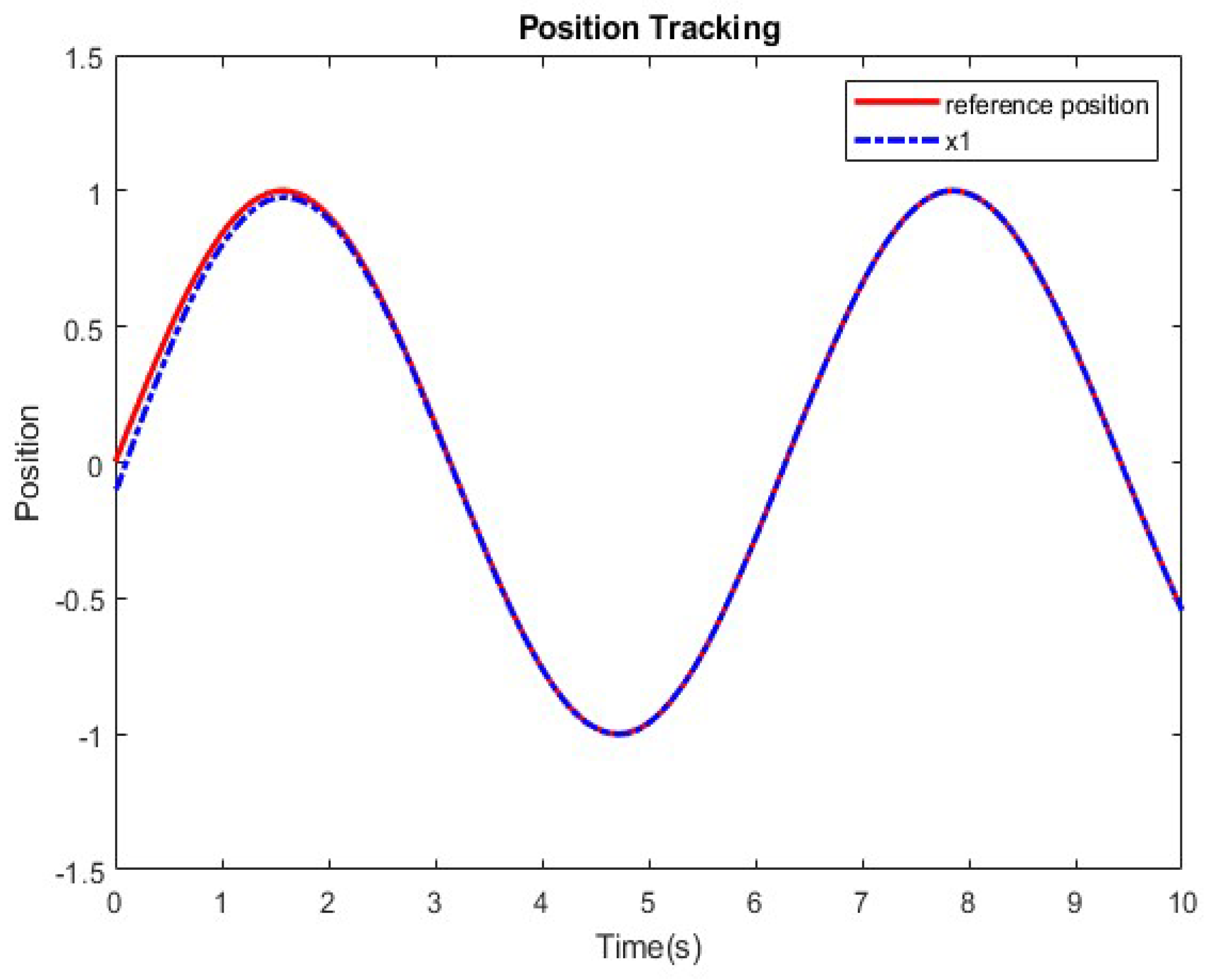
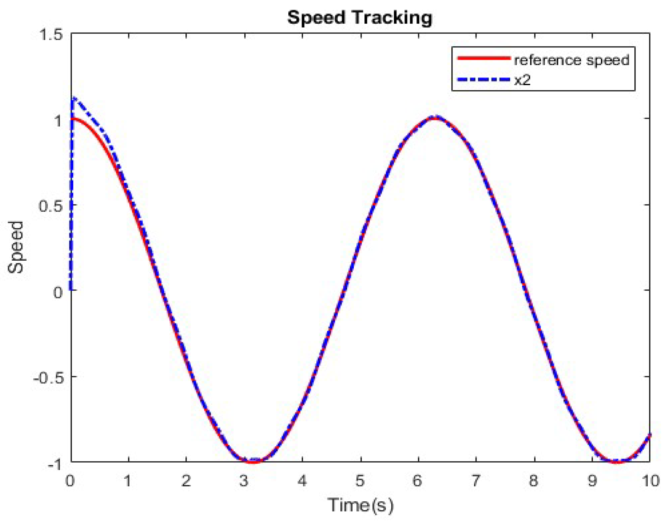
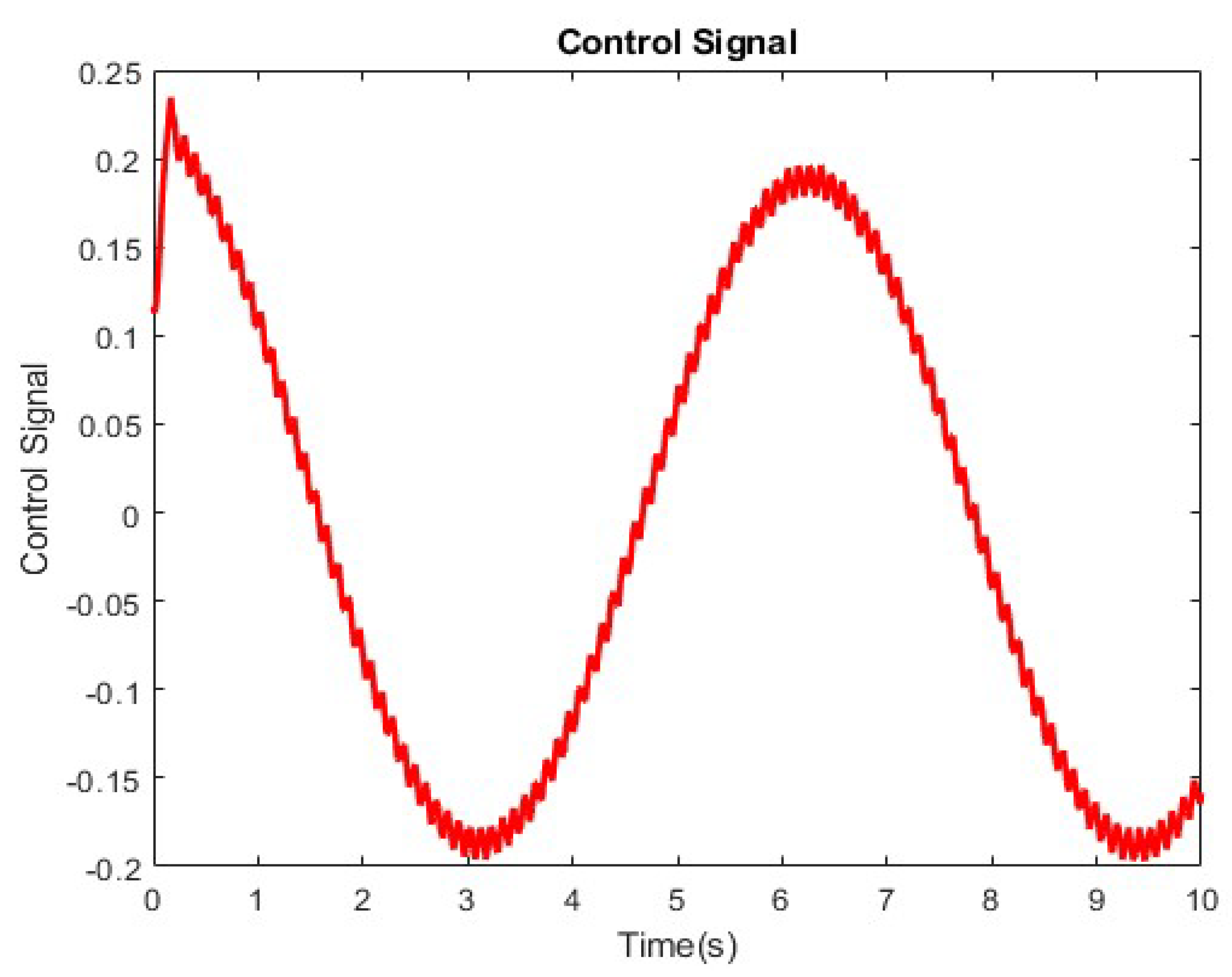
Figure 4 and Figure 5 depict the application of the proposed controller CECFSMC-ESMO in the tracking of the sinusoid reference r ( t ) = sin ( ω r t ) ,   ω r = 1 Hz. As is seen, the closed-loop response exhibits a good ability in the tracking of the reference signal, even under the presence of disturbance, with no steady state errors within a short, fixed time of 2 s. This result is consistent with the control input seen in Figure 6, where the input signal approaches a typical sinusoidal signal after 2 s, albeit with a little chattering. Note that it is also possible to reduce this chattering further in the real-world implementation of the proposed controller with the use of the signr function introduced in [42]. Nevertheless, the closed-loop system is demonstrated to be robust, with a proper convergence rate.
Figure 7 shows the phase-plane trajectory response of the system under constant exponent coefficient fixed-time control based on finite-time ESMO. It expresses that the phase trajectory exhibits convergence performance to a small neighborhood of the origin from the initial state within a fixed time. It again indicates that the system has a proper convergence rate and a smooth steady-state process.
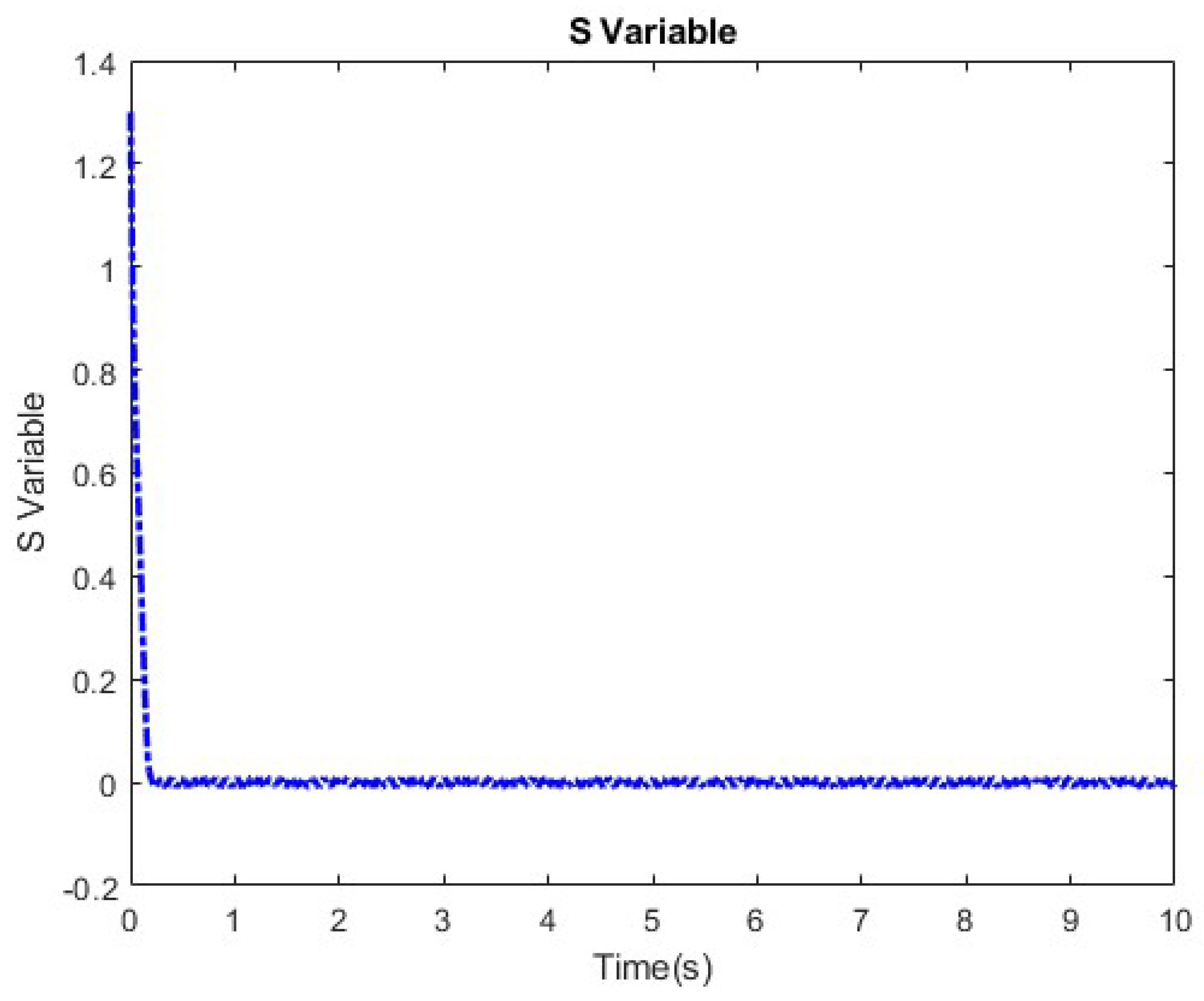
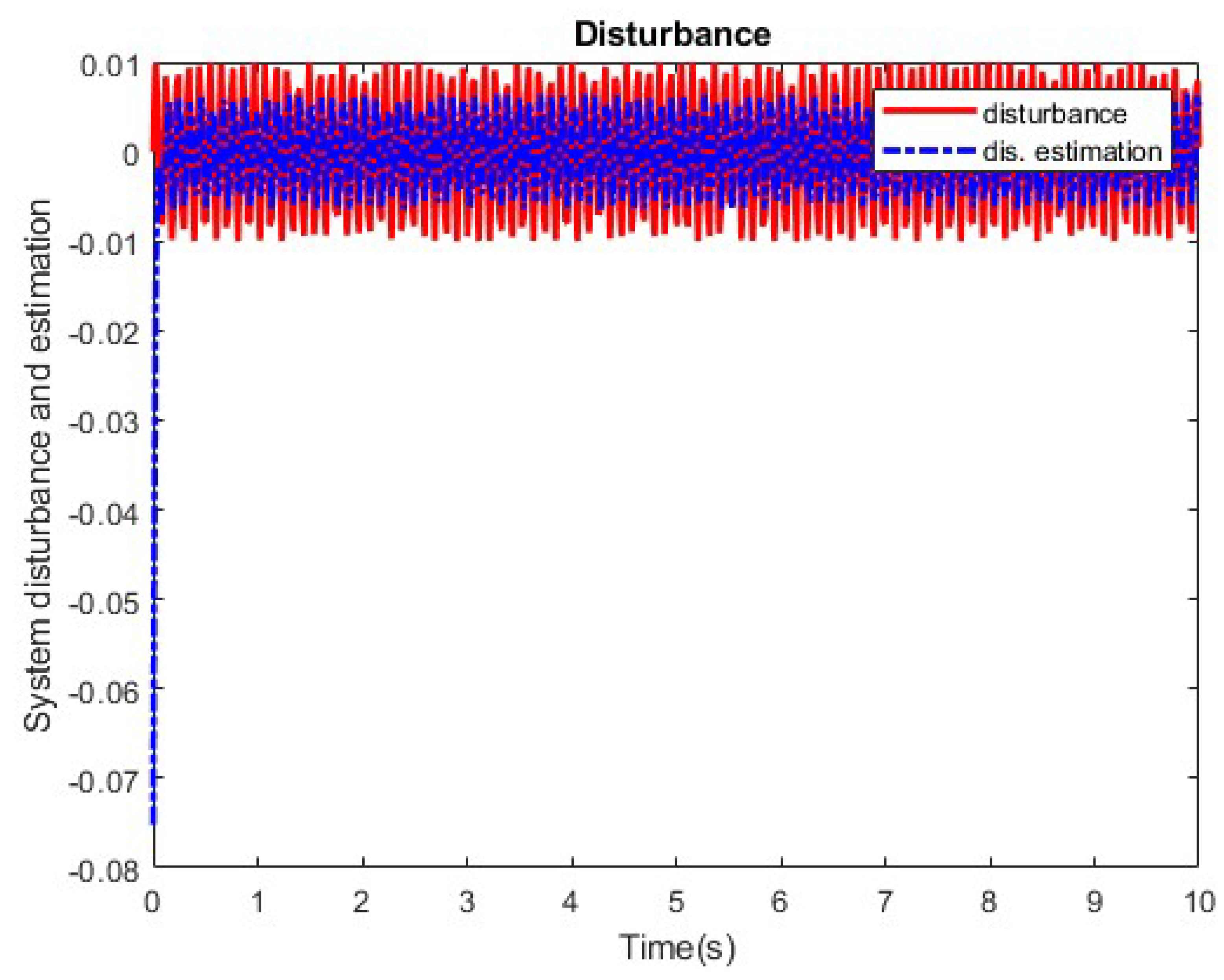
Figure 8 shows that sliding mode variable converges to zero in a short fixed time and under a constant exponent coefficient fixed-time controller. Finally, Figure 9 illustrates the estimated disturbances calculated by the in comparison to the system disturbance σ ( t ) = 0.01 sin ( 60 t ) . It is apparent from the figure that the presented ESMO gives a good estimation of the total disturbance, with its convergence occurring in finite-time as designed.
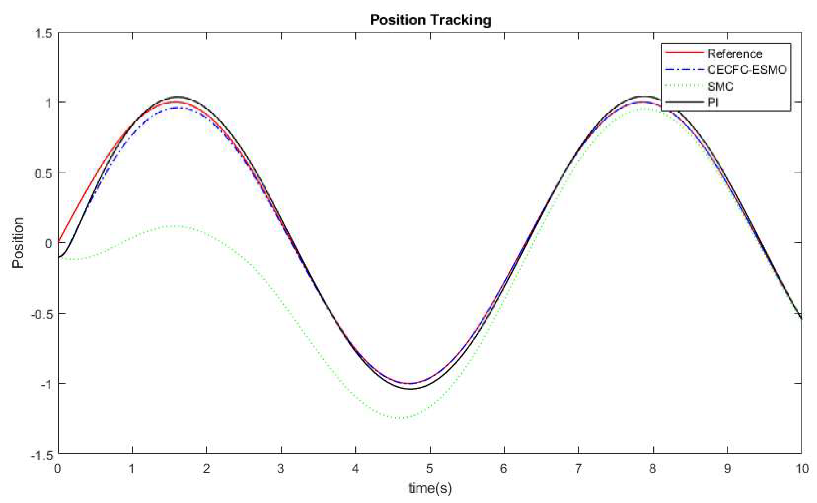
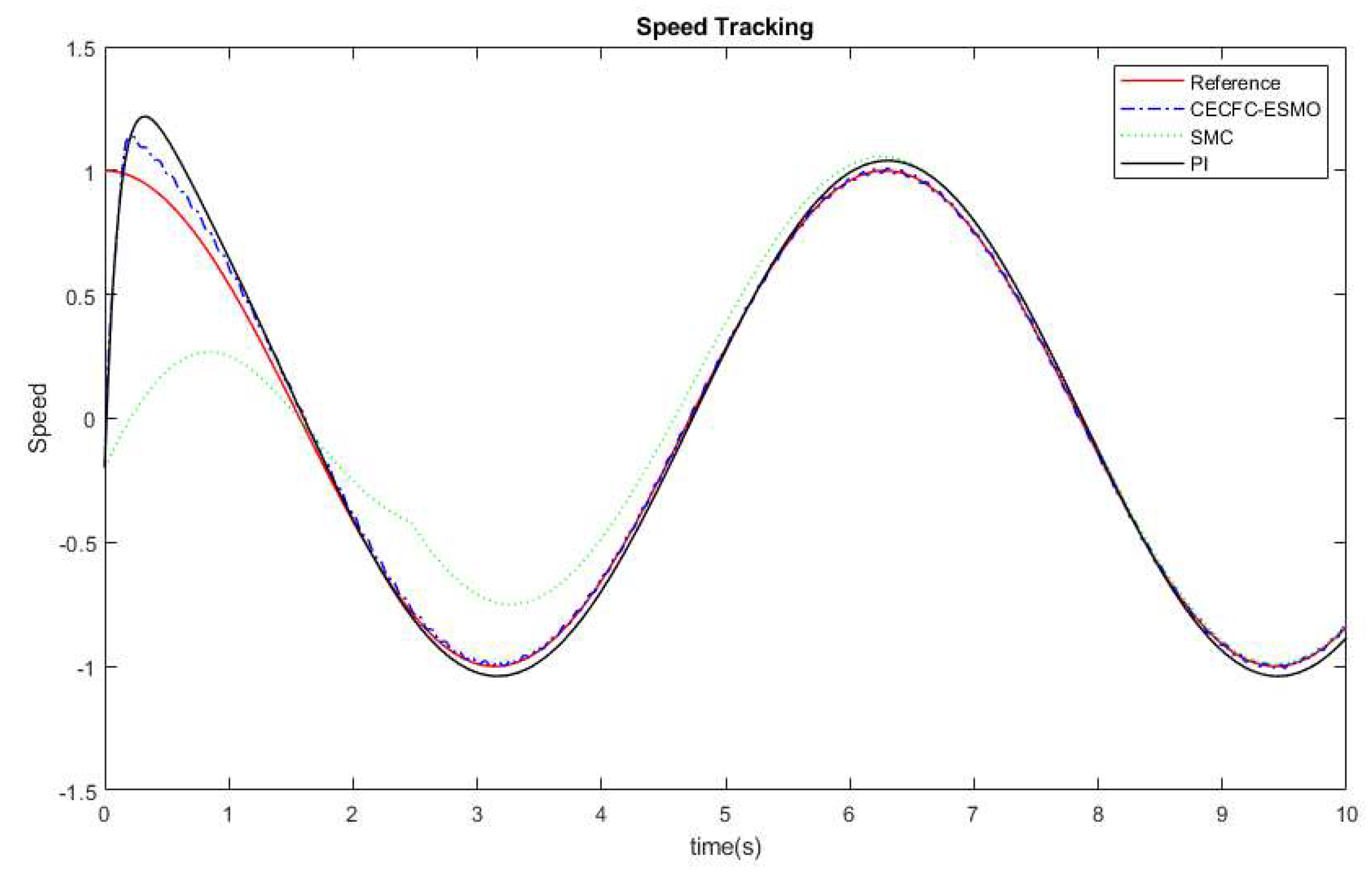
Figure 10 and Figure 11 depict the comparison between the PI controller, the conventional SMC, and the proposed controller scheme CECFSMC-ESMO. As is seen, the PI controller exhibits good tracking for both position and speed. However, it is important to note that a persistent steady-state error persists due to the influence of the generated disturbances. The conventional SMC has quite a poor response at the beginning of the simulation, only being able to track the reference after some 8 s. This is simply because although SMC is known to persist against disturbances, the basic reaching law simply cannot cope with the high frequency content of the disturbance. Note that before the attainment of the reaching time T r e a c h , the controller takes into consideration the observer variable, resulting in the generation of the overall control signal, as specified in (52). Even though the observer successfully estimates disturbances within a finite time of less than one second, there may still be some residual errors requiring mitigation by the CECFSMC. Consequently, this extends the convergence time to approximately 2 s. Note also that although this time could be made shorter by the increment of the parameters c 2 and k 1 in theory, as discussed in Remark 2, choosing these parameters at too high a value could exacerbate chattering, which would result in detrimental effects on the PMSM, incurring substantial costs in industrial settings.

5. Conclusions

This paper introduces a novel control technique for regulating the speed of the PMSM using fixed-time stability and a constant exponent coefficient. It presents a mathematical model of the PMSM that takes into account uncertainties and load disturbances. The SMC is then made to improve the system dynamics by utilizing robust fixed-time stability with a constant exponent coefficient. This makes sure that the reaching time is less than T(x0). A composite SMC technique utilizing a finite-time ESMO for estimating disturbances is then designed to counteract the effect of matched and unmatched disturbances. A feedback regulation mechanism is incorporated to ensure satisfactory closed-loop performance based on SMC. Additionally, a feed-forward compensation technique is employed to counteract system disturbances. A finite-time stability proof is given for the extended sliding mode observer, while fixed-time stability proofs were given for the fixed-time sliding mode control, both in the absence and presence of disturbances. A guideline of parameters tuning is also given to ensure that the chattering phenomenon is sufficiently suppressed, whilst also retaining stability. Moreover, the proposed CECFSMC-ESMO gives a simple platform where the controller only has six parameters to tune, as opposed to other fixed-time algorithms that have much more tuning parameters, whilst still retaining a good reaching time under the presence of disturbances. Numerical simulation results show that the proposed method is robust against load disturbances, has better convergence, and has a reaching time of less than 2 s, thereby demonstrating that the proposed fixed-time constant exponent coefficient offers a good performance and is much simpler than the conventional finite-time method. For future works, this developed controller can be used with a higher order nonlinear system to further reduce the chattering phenomenon.

Author Contributions

Conceptualization, W.T. and N.W.; methodology, W.T.; software, V.C.; supervision, W.T. and N.W.; validation, W.T. and N.W.; writing—original draft, V.C.; writing—review and editing, W.T. and N.W. All authors have read and agreed to the published version of the manuscript.

Funding

This work was financially supported by King Mongkut’s Institute of Technology Ladkrabang, Contract no. 2566-02-01-043.

Data Availability Statement

Not applicable.

Acknowledgments

The authors appreciate the support and infrastructure provided by the Department of Instrumentation and Control Engineering, School of Engineering, King Mongkut’s Institute of Technology Ladkrabang (KMITL) for the completion of this work. The authors would also like to appreciate the manuscript’s anonymous reviewers for their insightful comments and suggestions.

Conflicts of Interest

The authors declare no conflict of interest.

References

  1. Wang, Y.; Xu, Y.; Zou, J. Sliding-mode sensorless control of PMSM with inverter nonlinear compensation. IEEE Trans. Power Electron. 2019, 34, 10206–10220. [Google Scholar] [CrossRef]
  2. Ruuskanen, V.; Nerg, J.; Rilla, M.; Pyrhonen, J. Iron loss analysis of the permanent-magnet synchronous machine based on finite-element analysis over the electrical vehicle drive cycle. IEEE Trans. Ind. Electron. 2016, 63, 4129–4136. [Google Scholar] [CrossRef]
  3. Sheng, L.; Li, W.; Wang, Y.; Fan, M.; Yang, X. Sensorless control of shearer short-range cutting interior permanent magnet synchronous motor based on a new sliding mode observer. IEEE Access 2017, 5, 18439–18450. [Google Scholar] [CrossRef]
  4. Fan, S.; Tong, C. Model predictive current control method for PMSM drives based on an improved prediction model. J. Power Electron. 2020, 20, 1456–1466. [Google Scholar] [CrossRef]
  5. Jiang, C.; Wang, Q.; Li, Z.; Zhang, N.; Ding, H. Nonsingular terminal sliding mode control of PMSM based on improved exponential reaching law. Electronics 2021, 10, 1776. [Google Scholar] [CrossRef]
  6. Wang, C.; Zhu, Q. Fuzzy logic speed control of Permanent magnet synchronous machine and feedback voltage ripple reduction in flux-weakening operation region. IEEE Trans. Ind. Appl. 2022, 56, 1505–1517. [Google Scholar] [CrossRef]
  7. Lin, F.-J.; Yang, K.-J.; Sun, I.-F.; Chang, J.-F. Intelligent position control of permanent magnet synchronous motor using recurrent fuzzy neural cerebellar model articulation network. IET Electr. Power Appl. 2015, 9, 248–264. [Google Scholar] [CrossRef]
  8. Nguyen, A.T.; Rafaq, M.S.; Choi, H.H.; Jung, J.-W. A model reference adaptive control-based speed controller for a surface-mounted permanent magnet synchronous motor drive. IEEE Trans. Ind. Electrons 2018, 65, 9399–9409. [Google Scholar] [CrossRef]
  9. Zhanga, G.; Gao, L.; Yang, H.; Mei, L. A novel method of model predictive control on permanent magnet synchronous machine with Laguerre function. Alex. Eng. J. 2021, 6, 5485–5494. [Google Scholar] [CrossRef]
  10. Wang, T.; Li, J.; Liu, Y. Synergetic control of permanent magnet synchronous motor based on load torque observer. Proc. Inst. Mech. Eng. Pt. I J. Syst. Contr. Eng. 2018, 233, 980–993. [Google Scholar] [CrossRef]
  11. Mu, C.; Xu, W.; Sun, C. On switching manifold design for terminal sliding mode control. J. Frankl. Inst. 2016, 353, 1553–1572. [Google Scholar] [CrossRef]
  12. Zaihidee, F.M.; Mekhilef, S.; Mubin, M. Robust speed control of PMSM using sliding mode control (SMC)—A Review. Energies 2019, 12, 1669. [Google Scholar] [CrossRef]
  13. Lin, Y.; Hu, K.; Yeh, T.; Liaw, C.-M. An electric-vehicle IPMSM drive with interleaved front-end DC/DC converter. IEEE Trans. Veh. Technol. 2016, 6, 4493–4505. [Google Scholar] [CrossRef]
  14. Napole, C.; Derbeli, M.; Barambones, O. A global integral terminal sliding mode control based on a novel reaching law for a proton exchange membrane fuel cell system. Appl. Energy. 2021, 301, 11743–11757. [Google Scholar] [CrossRef]
  15. Benosman, M.; Lum, K.Y. Passive actuators’ fault-tolerant control for affine nonlinear control systems. IEEE Trans. Control Syst. Technol. 2010, 18, 152–163. [Google Scholar] [CrossRef]
  16. Yang, Y.; Yan, Y. Neural network approximation-based nonsingular terminal sliding mode control for trajectory tracking of robotic ariships. Aerosp. Sci. Technol. 2016, 54, 192–197. [Google Scholar] [CrossRef]
  17. Bartoszewicz, A.; Lesniewskil, P. New switching and nonswitching type reaching laws for SMC of discrete time systems. IEEE Trans. Control Syst. 2016, 24, 670–677. [Google Scholar] [CrossRef]
  18. Wang, Y.; Feng, Y.; Zhang, Z.; Liang, J. A new reaching law for antidisturbance sliding-mode control of PMSM speed regulation system. IEEE Trans. Power Electron. 2020, 35, 4117–4126. [Google Scholar] [CrossRef]
  19. Ma, H.; Li, Y. Multi-power reaching law based discrete-time sliding-mode control. IEEE Access 2019, 7, 49822–49829. [Google Scholar] [CrossRef]
  20. Polykov, A. nonlinear feedback design for fixed-time stabilization of linear control system. IEEE Trans. Autom. Control. 2012, 57, 2106–2110. [Google Scholar] [CrossRef]
  21. Chen, C.; Li, L.; Peng, H.; Yang, Y.; Mi, L.; Zhao, H. A new fixed-time stability theorem and its application to the fixed-time synchronization of neural networks. Neural Netw. 2020, 123, 412–419. [Google Scholar] [CrossRef]
  22. Hu, C.; Yu, J.; Chen, Z.; Jiang, H.; Huang, T. Fixed-time stability of dynamical systems and fixed-time synchronization of coupled discontinuous neural networks. Neural Netw. 2017, 89, 74–83. [Google Scholar] [CrossRef]
  23. Parsegov, S.; Polyakov, A.; Shcherbako, V. Nonlinear fixed-time control protocol for uniform allocation of agents on segment. In Proceedings of the 51st IEEE Conference on Decision and Control, Maui, HI, USA, 10–13 December 2012; pp. 7732–7737. [Google Scholar] [CrossRef]
  24. Polyakov, A.; Fridman, L. Stablity notion and Lyapunov functions for sliding mode control systems. J. Frankl. Inst. 2014, 351, 1831–1865. [Google Scholar] [CrossRef]
  25. Moulay, E.; Lechappe, V.; Bernau, E.; Plestan, F. Robust fixed-time stability: Application to sliding mode control. IEEE Trans. Autom. Control. 2022, 67, 1061–1066. [Google Scholar] [CrossRef]
  26. Junejo, A.; Liu, Y.; Islam, M.D. Improved continuous fast terminal sliding mode control with extended state observer for speed regulation of PMSM drive system. IEEE Trans. Veh. Technol. 2019, 68, 10465–10476. [Google Scholar] [CrossRef]
  27. Xu, W.; Junejo, A.K.; Xu, W. Adaptive speed control of PMSM drive system based a new sliding-mode reaching law. IEEE Trans. Power Electron. 2020, 35, 12110–12121. [Google Scholar] [CrossRef]
  28. Liu, Y.-C.; Laghrouche, S.; Depernet, D.; N’Diaye, A.; Djerdir, A.; Cirrincione, M. Super-twisting sliding-mode observer-based model reference adaptive speed control of PMSM drives. J. Frankl. Inst. 2023, 360, 985–1004. [Google Scholar] [CrossRef]
  29. Zhang, L.; Tao, R.; Zhang, Z.-X.; Chien, Y.-R.; Bai, J. PMSM non-singular fast terminal sliding mode control with disturbance compensation. Inf. Sci. 2023, 642, 119040. [Google Scholar] [CrossRef]
  30. Yacef, F.; Rizoug, N.; Degaa, L.; Bouhali, O.; Hamerlain, M. Extended state observer-based adaptive fuzzy tracking control for a quadrotor UAV. In Proceedings of the 2018 5th International Conference on Control, Decision and Information Technologies (CoDIT), Thessaloniki, Greece, 10–13 April 2018; pp. 1023–1028. [Google Scholar] [CrossRef]
  31. Liu, K.; Wang, R. Antisaturation adaptive fixed-time sliding mode controller design to achieve faster convergence rate and its application. IEEE Trans. Circuits Syst. II Express Briefs. 2022, 69, 3555–3559. [Google Scholar] [CrossRef]
  32. Liu, K.; Wang, Y.; Ji, H. Adaptive finite-time tracking control for spacecraft proximity operations under actuator saturation. In Proceedings of the 2020 International Conference on Unmanned Aircraft Systems (ICUAS), Athens, Greece, 1–4 September 2020; pp. 1344–1349. [Google Scholar] [CrossRef]
  33. Lara, J.; Xu, J.; Chandra, A. Effects of rotor position error in the performance of field-oriented-controlled PMSM drives for electric vehicle traction applications. IEEE Trans. Ind. Electron. 2016, 63, 4738–4751. [Google Scholar] [CrossRef]
  34. Li, S.; Zhou, M.; Yu, X. Design and implementation of terminal sliding mode control method for PMSM speed regulation system. IEEE Trans. Ind. Inform. 2013, 9, 1879–1891. [Google Scholar] [CrossRef]
  35. Baht, S.; Berstein, D. Finite-time stability of continuous autonomous systems. SIAM J. Control Optim. 2000, 38, 751–766. [Google Scholar] [CrossRef]
  36. Moulay, E.; Perruquetti, W. Finite time stability and stabilization of a class of continuous systems. J. Math. Anal. Appl. 2006, 323, 1430–1433. [Google Scholar] [CrossRef]
  37. Polyakov, A.; Efimov, D.; Perruquetti, W. Finite-time and fixed-time stabilization: Implicit Lyapunov function approach. Automatica 2015, 51, 332–340. [Google Scholar] [CrossRef]
  38. Zou, Z.; Han, Q.; Ning, B. Fixed-Time Cooperative Control of Multi-Agent Systemsi; Springer: Berlin/Heidelberg, Germany, 2019. [Google Scholar]
  39. Han, J. From PID to active disturbance rejection control. IEEE Trans. Ind. Electron. 2009, 56, 900–906. [Google Scholar] [CrossRef]
  40. Kawski, M. Geometric homogeneity and stabilization. IFAC Proc. Vol. 1995, 28, 147–153. [Google Scholar] [CrossRef]
  41. Bhat, S.P.; Bernstein, D.S. Geometric to homogeneity with applications finite-time. Math. Control. Signals Syst. 2005, 17, 101–127. [Google Scholar] [CrossRef]
  42. Wongvanich, N.; Roongmuanpha, N.; Tangsrirat, W. Finite-time integral backstepping nonsingular terminal sliding mode control to synchronize a new six-term chaotic system and its circuit implementation. IEEE Access 2023, 11, 22233–22249. [Google Scholar] [CrossRef]
  43. Halledj, S.E.; Bouafassa, A. Anti-disturbance GITSMC with quick reaching law for speed control of PMSM drive. Bull. Electr. Eng. Inform. 2022, 11, 3228–3238. [Google Scholar] [CrossRef]
  44. Wan, Q.; Wang, H.; Sun, X. Position tracking control of PMSM system based on continuous sliding mode control and sliding mode observer. In Proceedings of the 2022 41st Chinese Control Conference (CCC), Hefei, China, 25–27 July 2022; pp. 2917–2922. [Google Scholar] [CrossRef]
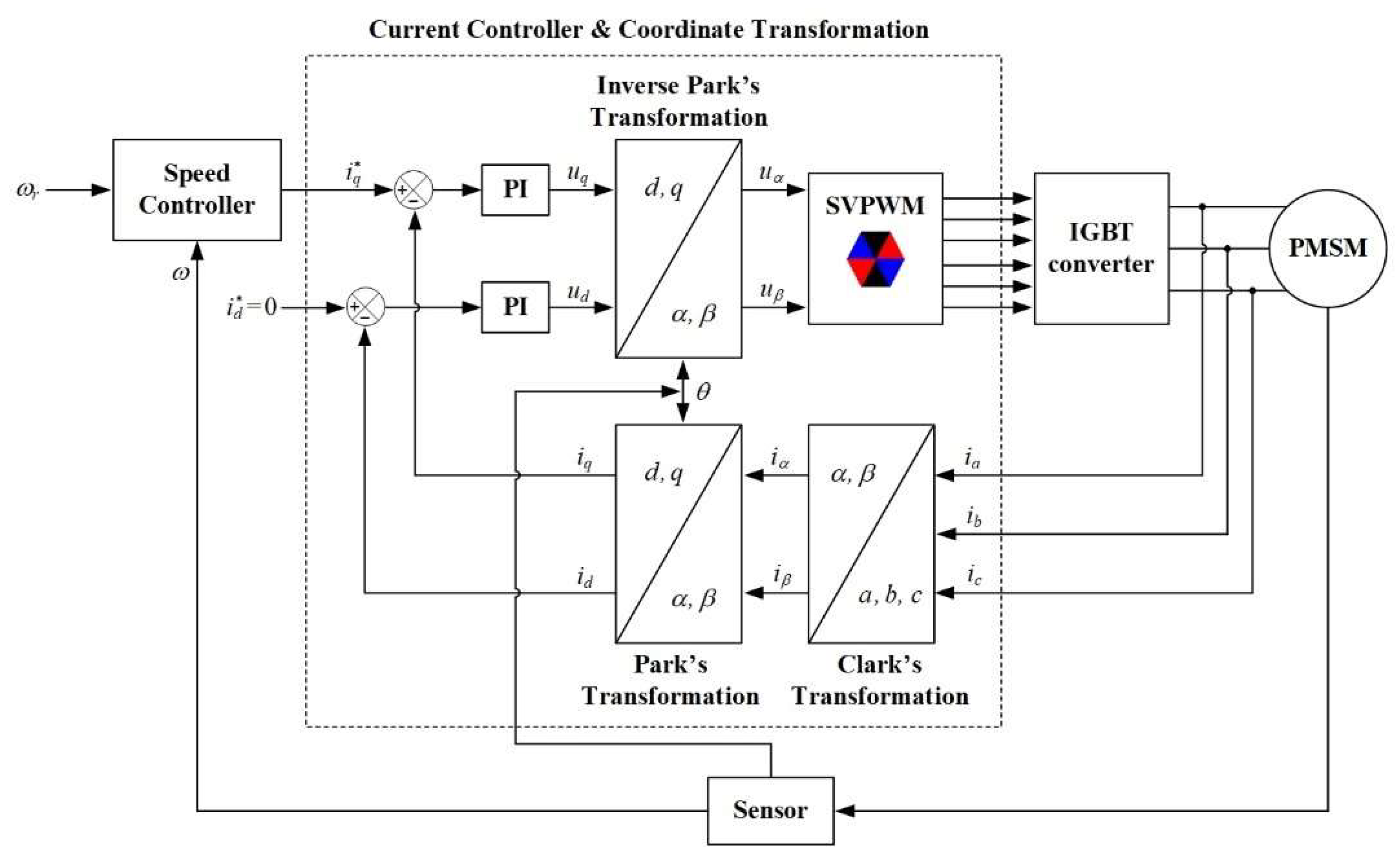
Figure 1. Block diagram of PMSM FOC variable speed control.
Energies 16 07454 g001
Figure 2. Block diagram of fixed-time control with conventional sliding-mode surface.
Energies 16 07454 g002
Figure 3. Block diagram of fixed-time controller with a conventional sliding mode surface and a finite-time extended sliding mode observer.
Energies 16 07454 g003
Figure 4. Position tracking x1(t) plotted versus time.
Energies 16 07454 g004
Figure 5. Speed tracking x2(t) plotted versus time.
Energies 16 07454 g005
Figure 6. Control signal i q plotted versus time.
Energies 16 07454 g006
Figure 7. Phase plane trajectory plotted under disturbance.
Energies 16 07454 g007
Figure 8. Trajectory of the s-variable of (18).
Energies 16 07454 g008
Figure 9. Comparison between the system disturbance against its estimation from the ESMO (26).
Energies 16 07454 g009
Figure 10. The comparison between a PI controller, the conventional controller, and the proposed controller for the position response.
Energies 16 07454 g010
Figure 11. The comparison between a PI controller, the conventional controller, and the proposed controller for the speed response.
Energies 16 07454 g011
Table 1. Parameters of the servo motor used in simulation [43].
ParameterValueUnit
Number of pole pairs np6-
Rated power P0.4kW
Stator resistance Rs1.55 Ω
dq-axis inductance L6.71mH
Rotational inertia J0.0054kg.m2
flux linkage φf0.174Wb
Viscous damping B0.00072N.m.s
Disclaimer/Publisher’s Note: The statements, opinions and data contained in all publications are solely those of the individual author(s) and contributor(s) and not of MDPI and/or the editor(s). MDPI and/or the editor(s) disclaim responsibility for any injury to people or property resulting from any ideas, methods, instructions or products referred to in the content.