Abstract
As the core device of engine-driven vehicle powertrains, the automatic transmission (AT) can obtain different output torques and speeds. Designing new mechanisms is the foundation for developing innovative ATs. This paper proposes an innovative design method for 7-speed, 8-speed and 9-speed AT mechanisms based on fractionated planetary gear trains (PGTs) and investigates the performance analysis of the AT mechanisms. Firstly, the detection of symmetric vertices in the PGT graph is studied, and a method for the topologic synthesis of 11-link 2-degree-of-freedom (DOF) fractionated PGTs is proposed. Secondly, the innovative design of 7-speed, 8-speed and 9-speed AT mechanisms is explored, leading to the discovery of two novel 7-speed AT mechanisms, three novel 8-speed AT mechanisms and four novel 9-speed AT mechanisms. Finally, the performance analyses of kinematics, torque, power flow and transmission efficiency of the AT mechanisms are conducted, and AMESim (Simcenter Amesim 2020.1) software is utilized to simulate speed ratios and transmission efficiencies of the AT mechanisms. The analysis and simulation results demonstrate that the nine novel AT mechanisms obtained in this study exhibit excellent overall performances. The speed ratios of each AT mechanism are reasonable, the step ratio is between 1.1 and 1.8, and the transmission efficiency exceeds 0.95. There is no cyclic power, or the cyclic power values are within an acceptable limit.
1. Introduction
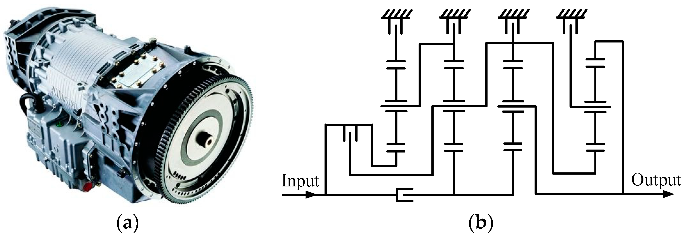
As the core device of engine-driven vehicle powertrains, the automatic transmission (AT) can obtain different output torques and speeds. In the 1940s, General Motors in the United States developed the world’s first truly mass-produced AT. Since then, ATs have been widely installed in various civilian and military vehicles. Due to their advantages such as good fuel economy, high transmission efficiency, high torque capacity and smooth shifting, ATs with seven or more forward gears are usually used in luxury vehicles. Japanese Aisin company produced the world’s first 8-speed AT called AA80E. German Mercedes-Benz company invented the 9G-Tronic 9-speed AT. Figure 1a shows the HD4070 7-speed AT [1], which is developed by the U.S. company Allison. The speed ratios of its seven forward gears are 7.63, 3.51, 1.91, 1.43, 1, 0.74 and 0.64, respectively, and its reverse speed ratio is −4.8. This AT has been applied in heavy-duty commercial and military vehicles. The corresponding schematic diagram of the mechanism is shown in Figure 1b.
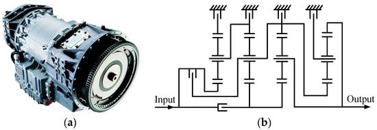
Figure 1.
Allison HD4070 AT (a) and the corresponding schematic diagram of mechanism (b).
The design of new mechanisms is the source and foundation for developing new ATs [2]. Over the past few decades, researchers have conducted extensive studies on designing AT mechanisms. Hsu and Huang [3] analyzed the speed ratio of an 8-link 2-DOF Ravigneaux PGT and designed a 6-speed AT mechanism. Based on given clutch sequences of PGTs, Hwang and Huang [4] studied the valid layout of control elements of the corresponding AT mechanisms. Esmail [5] used nomographs to study the design of Ravigneaux PGT-type AT mechanisms. Xie et al. [6] combined a high reduction ratio PGT with 6-speed AT mechanisms to design 7-speed AT mechanisms suitable for heavy-duty vehicles. Peng et al. [7] designed 6-, 7- and 8-speed AT mechanisms by changing the interconnection of edges in PGT graph. Yang et al. [8] presented a power flow analysis and configuration design method for AT mechanisms with hybrid gear trains. Dong et al. [9] designed a 4-DOF multi-speed AT mechanism for front-wheel-drive vehicle by combining PGTs and parallel-axis gear trains. Based on the lever diagram of planetary gear sets, Liu et al. [10] proposed a configuration design method for multi-speed ATs suitable for single and hybrid inputs. By determining design constraints, Hoang and Yan [11] studied a method for generating electric vehicle transmission mechanisms from 6-link kinematic chains and performed simulations using Matlab/Simulink. Du and Yang [12] proposed an automatic analysis method for structural components and dynamic parameters of multi-input transmission systems under different operating conditions. Based on graph theory and lever analogy, Ho and Hwang [13] designed hybrid transmission mechanisms by combining 6-link Ravigneaux PGTs and a single planetary gear set.
Most existing methods use combinations of planetary gear sets to accomplish the design of AT mechanisms or make improvements based on the already designed mechanisms. These methods have a higher probability of trial and error, a lower design efficiency, and are prone to appear with isomorphic configurations. Furthermore, they can only generate a limited number of configurations. A method based on the synthesis of PGT graphs can effectively address the aforementioned issues.
Buchsbaum and Freudenstein [14] first introduced the concept of topological graph of PGT into the field of PGT synthesis. Tsai and Lin [15,16] presented a recursive method to synthesize 1- and 2-DOF non-fractionated PGTs. Hsu et al. [17] presented a new PGT graph model called acyclic graph, based on which 1-DOF non-fractionated PGTs with up to 8 links were successfully synthesized. Del Castillo [18] presented the PGT graph with three-level vertices to synthesize 1-DOF non-fractionated PGTs satisfying given constrains. Rao and Rao [19] applied Hamming matrix to detect isomorphism and studied the synthesis of 1-DOF non-fractionated PGTs via the recursive method. Yang et al. [20,21] developed the perimeter loop-based method to detect isomorphism and synthesized 1- and 2-DOF non-fractionated PGTs with up to nine links. Based on the acyclic graph, Shanmukhasundaram et al. [22] developed the combination of edge labeled kinematic units for the synthesis of 1-DOF non-fractionated PGTs. Cui et al. [23] constructed a structure invariant for the isomorphism detection and synthesized 1-DOF non-fractionated PGTs from their parent graphs.
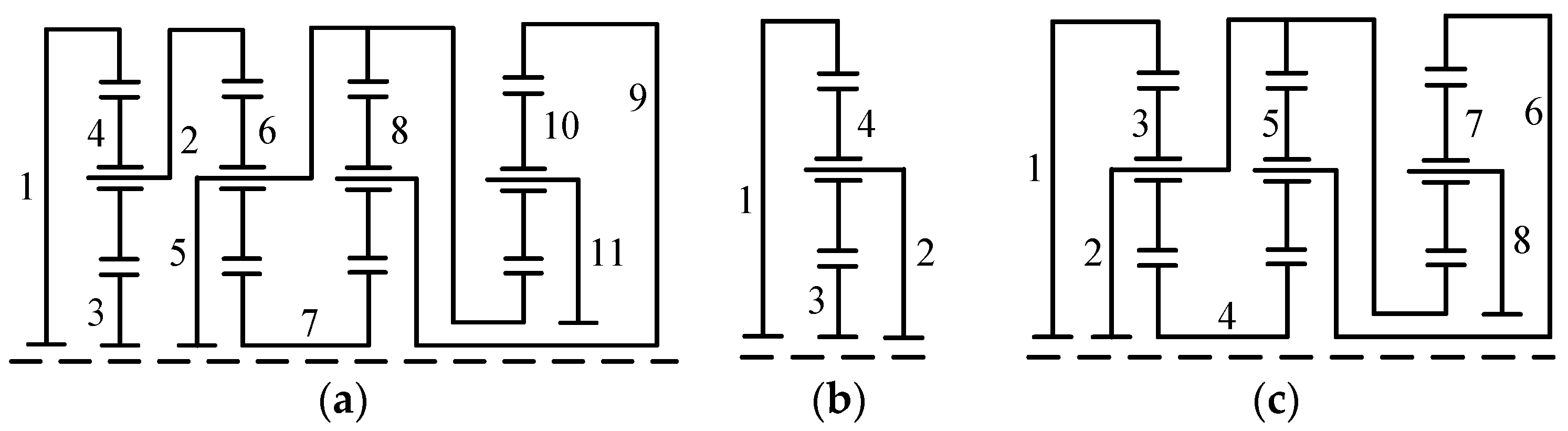
Existing synthesis methods are mainly used for synthesizing non-fractionated PGT graphs. However, apart from non-fractionated PGTs, fractionated PGTs are also frequently used in the design of AT mechanisms. For example, the PGT corresponding to the mechanism in Figure 1b is a fractionated 11-link 2-DOF PGT, as shown in Figure 2a. It can be separated into a 4-link 1-DOF PGT and an 8-link 1-DOF PGT, as illustrated in Figure 2b,c, respectively. Due to the lack of synthesis methods for fractionated PGTs, a large number of novel high-performance AT mechanisms, whose core structures are fractionated PGTs, are still yet to be designed.

Figure 2.
The PGT corresponding to the mechanism in Figure 1b (a), a 4-link 1-DOF PGT (b), and an 8-link 1-DOF PGT (c), where links are numbered from 1 to 11.
This paper investigates the synthesis of 11-link 2-DOF fractionated PGT graphs, based on which a systematic innovative design method for 7-speed, 8-speed and 9-speed AT mechanisms is proposed. Two novel 7-speed AT mechanisms, three novel 8-speed AT mechanisms and four novel 9-speed AT mechanisms are obtained, including one 7-speed AT mechanism suitable for heavy-duty vehicles. This paper also conducts the analyses of kinematics, torque, power flow and transmission efficiency of the AT mechanisms, and applies AMESim software to simulate their speed ratios and transmission efficiencies. The analysis and simulation results demonstrate that all nine novel AT mechanisms obtained in this study exhibit excellent overall performances.
2. Topological Synthesis of 11-Link 2-DOF Fractionated PGTs
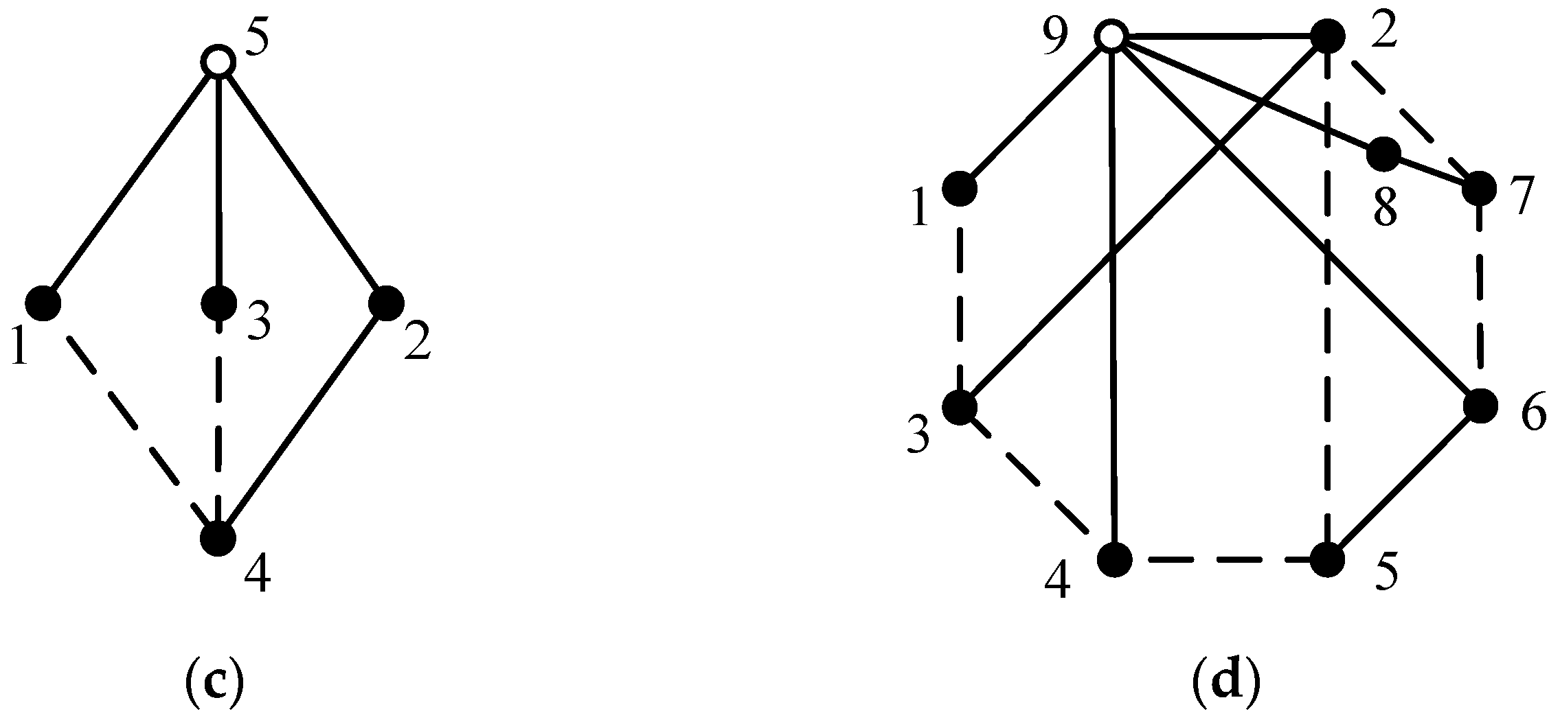
For convenience of computer progressing, the structure of PGT is usually represented by its topological graph, where a solid vertex, a hollow vertex, a solid edge and a dashed edge represent a link, a multiple joint, a revolute pair and a geared pair, respectively. For example, the topological graph of the PGT in Figure 2a is shown in Figure 3a. Multiple joints 12 and 13 in Figure 3a are equivalent to one multiple joint, namely, the multiple joint formed by central links rotating around the main shaft of AT. The equivalent topological graph of Figure 3a is shown in Figure 3b. The topological graphs of the PGTs in Figure 2b,c are shown in Figure 3c,d, respectively. The adjacency matrix of a PGT graph is defined by Equation (1), where n is the total number of vertices (including solid and hollow vertices), ai,j is the element in ith row and jth column of the matrix, and d is the degree of a hollow vertex. For example, the adjacency matrices of Figure 3c,d are shown as AM1 and AM2 in Equation (2), respectively. A d-degree hollow vertex is equivalent to (d − 1) revolute pairs.
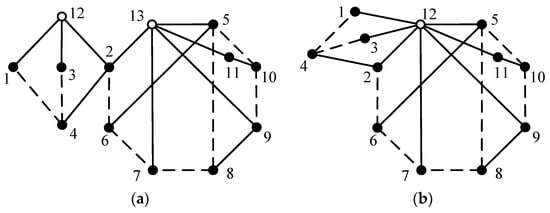
The graph in Figure 3a is a vertex-fractionated graph that can be separated into two independent sub-graphs (namely, Figure 3c,d) at vertex 2. In reverse, by combining vertex 2 in Figure 3c and vertex 1 in Figure 3d, the graph in Figure 3a can be derived. The DOF equation of a PGT is
where N, R and G are the numbers of links, revolute pairs and geared pairs, respectively. The DOF of the PGT in Figure 3a is F = 3(N − 1) −2R − G = 3 × (11 − 1) – 2 × 10−8 = 2, that is, Figure 3a represents an 11-link 2-DOF fractionated PGT. Similarly, Figure 3c,d represent a 4-link 1-DOF and an 8-link 1-DOF non-fractionated PGT, respectively. Generally, N1-link F1-DOF and N2-link F2-DOF non-fractionated PGTs can be combined to obtained (N1 + N2 − 1)-link (F1 + F2)-DOF fractionated PGTs. The topological graph of PGT in Figure 3a can be used to design 7-speed AT mechanisms, but it is not suitable for designing 8-speed and 9-speed AT mechanisms. We aim to synthesize 11-link 2-DOF fractionated topological graphs of PGTs, which can be used to design 7-speed, 8-speed and 9-speed AT mechanisms. This kind of topological graphs are generated by combing two 6-link 1-DOF non-fractionated topological graphs of PGTs.
F = 3(N − 1) − 2R − G
2.1. Detection of Symmetric Vertices in the PGT Graph
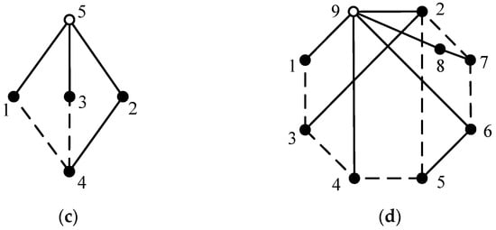
The total number of 6-link 1-DOF non-fractionated PGTs is 81, and the complete database of these PGTs can be found in the literature [17,20]. However, not all these 6-link 1-DOF PGTs can be used for the design of AT mechanisms. The constraints to be met for a given 6-link 1-DOF PGT are as follows: (1) there is one and only one multiple joint with the degree of four; (2) the topological graph of PGT is a planar graph in order to avoid link interferences; (3) the planetary gears on the same carrier do not mesh with each other internally; (4) each planetary gear meshes with one sun gear and one ring gear; and (5) the topological graph does not contain any loop composed solely of dashed edges (geared pairs). Among the total of 81 6-link 1-DOF PGT graphs, there are three that meet the aforementioned conditions, as shown in Figure 4.

Figure 4.
Three topological graphs of 6-link 1-DOF PGTs satisfying the specified constraints (a–c).
Theoretically, any two solid vertices in two 6-link 1-DOF PGT graphs g1 and g2 can be combined to obtain 11-link 2-DOF fractionated PGT graphs. However, a 6-link 1-DOF PGT graph may contain symmetric solid vertices that have identical topological characteristics. If two symmetric solid vertices in graph g1 are combined with one solid vertex from graph g2, respectively, the resulting two 11-link 2-DOF fractionated PGT graphs are isomorphic, meaning they are duplicate graphs with exactly the same topological structures. To avoid generating isomorphic 11-link 2-DOF PGT graphs, it is necessary to first identify non-symmetric vertices in 6-link 1-DOF PGT graphs. This paper proposes a simple method for detecting symmetry vertices, and the detection process is as follows.
Step 1: The weights of vertices in a given PGT graph are determined, and the vertices with the same weight are categorized in the same group. The weight wi of vertex i is the sum of the weights of edges incident with vertex i.
The weights of vertices in the PGT graph can be directly obtained from its adjacency matrix. The weight of vertex i is the sum of the elements in the i-th row of the adjacency matrix. For example, the adjacency matrix AM3 and vertex weights of Figure 4c are shown in Equation (4). Vertices 1, 6 and 7 have the same weight, so they are placed in the same group. Similarly, vertices 2 and 4 and vertices 3 and 5 are placed in the same groups, respectively. Therefore, the vertex groups are acquired as Group1 = {1, 6, 7}, Group2 = {2, 4} and Group3 = {3, 5}.
Step 2: The weight arrays of vertices in the PGT graph are determined, and vertices with the same weight array are placed in the same group. An array of numbers obtained by arranging the weights of vertices adjacent to vertex i in descending order is called the weight array of vertex i.
For example, vertex 1 in Figure 4c is adjacent to vertices 2, 4, 6 and 7, whose weights are 6, 6, 4 and 4, respectively. By arranging these four weights in descending order, the weight array of vertex 1 is obtained as (6, 6, 4, 4). Similarly, the weight arrays of vertices 2–7 of Figure 4c are (8, 8, 4), (6, 6, 4), (8, 8, 4), (6, 6, 4), (8, 4) and (8, 4), respectively. Vertices 2 and 4 have the same weight array, so they are placed in the same group. Similarly, vertices 3 and 5 and vertices 7 and 8 are placed in the same groups, respectively. The groups of vertices are acquired as Group1 = {1}, Group2 = {6, 7}, Group3 = {2, 4} and Group4 = {3, 5}. The vertices in different groups are clearly asymmetric. However, the vertices in the same group need to be further verified whether they are symmetric.
Step 3: If there is more than one vertex in the same group, the feature code of each vertex in the group is determined, and whether the vertices in the same group are symmetric is also determined by comparing whether their feature codes are the same. The process of obtaining the feature code of vertex i is as follows. New vertex groups are obtained by placing vertex i in the first group alone. The vertices in each group are permuted to obtain all possible ways of relabeling the PGT graph. For each relabeled PGT graph, its number string is obtained by concatenating the triangular elements of its adjacency matrix. The largest number string of all the relabeled PGT graphs is called the feature code of vertex i.
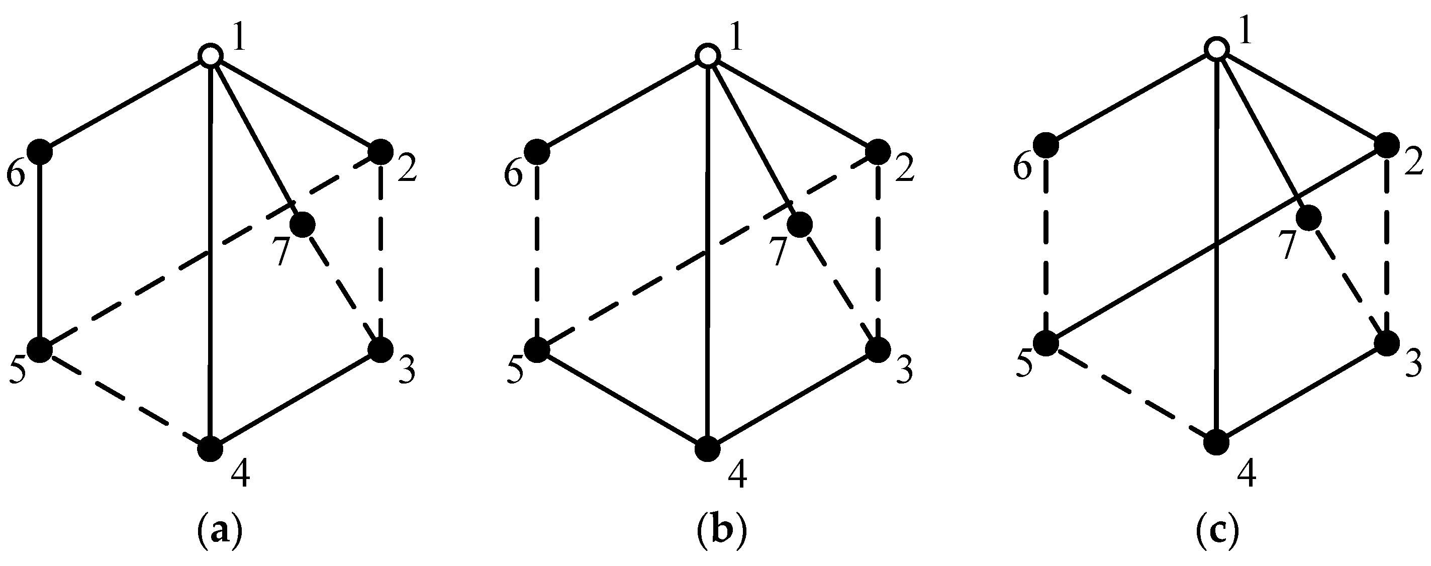
For example, let us consider whether vertices 6 and 7 in Group2 = {6, 7} are symmetric. The process of obtaining the feature code of vertex 6 in Figure 4c is as follows. Vertex 6 is placed separately in the first group, and the new vertex groups are acquired as Group1 = {6}, Group2 = {1}, Group3 = {7}, Group4 = {2, 4} and Group5 = {3, 5}. According to the permutations of vertices in each group, there are four ways to relabel the vertices in Figure 4c, namely, 1 ×1 × 1× 2 × 2 = 4. In the first way of relabeling, vertices 6, 1, 7, 2, 4, 3 and 5 in Figure 4c are, respectively, relabeled as 1 to 7, as shown in Figure 5a. In the second way of relabeling, vertices 6, 1, 7, 2, 4, 5 and 3 in Figure 4c are, respectively, relabeled as 1 to 7, as shown in Figure 5b. Similarly, the other two ways of relabeling are shown in Figure 5c,d. The adjacency matrices of the four relabeled graphs in Figure 5 are obtained as AM4, AM5, AM6 and AM7 in Equation (5), respectively. By concatenating the triangular elements of the adjacency matrix, the number strings of the four graphs in Figure 5 are obtained and shown in Table 1. Among the four number strings, NSd has the maximum value. Therefore, NSd = 100030-11100-0003-032-23-0 is determined as the feature code of vertex 6 in Figure 4c. Similarly, the process of obtaining the feature code of vertex 7 in Figure 4c is as follows. By placing vertex 7 separately in the first group, new vertex groups are obtained as Group1 = {7}, Group2 = {1}, Group3 = {6}, Group4 = {2, 4} and Group5 = {3, 5}. There are also four ways to relabel Figure 4c. The derived feature code of vertex 7 in Figure 4c is the same as that of vertex 6, i.e., Code6 = Code7 = 100030-11100-0003-032-23-0. Therefore, vertices 6 and 7 in Figure 4c are symmetric, and the reasoning process is as follows. The feature code Codei of vertex i has a strict one-to-one correspondence with that vertex. The feature code Code6 obtained by relabeling vertex 6 as 1 is equal to the feature code Code7 obtained by relabeling vertex 7 as 1. Hence, vertices 6 and 7 have exactly the same topological characteristics.
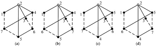
Figure 5.
The first (a), second (b), third (c) and fourth (d) ways of relabeling Figure 4c.

Table 1.
Number strings of the four graphs in Figure 5.
The symmetry detection results obtained by applying the above method to the topological graphs in Figure 4 are as follows. In Figure 4a, there are no symmetric vertices. In Figure 4b, vertices 3 and 5 are symmetric, and vertices 6 and 7 are symmetric, which are denoted as S1 = {3, 5} and S2 = {6, 7}. In Figure 4c, vertices 2 and 4 are symmetric, vertices 3 and 5 are symmetric, and vertices 6 and 7 are symmetric, which are denoted as S1 = {2, 4}, S2 = {3, 5} and S3 = {6, 7}.
2.2. Generation of Fractionated PGT Graphs and Functional Diagrams
By combining asymmetric solid vertices in two identical or different 6-link 1-DOF PGT graphs shown in Figure 4, all non-isomorphic 11-link 2-DOF fractionated PGT graphs can be obtained. For example, symmetric solid vertices in Figure 4c are S1 = {2, 4}, S2 = {3, 5} and S3 = {6, 7}; hence, the asymmetric solid vertices are {2, 3, 6}. By combining two PGT graphs shown in Figure 4c (denoted as graphs g1 and g2), that is, combining vertices 2, 3 and 6 in graph g1 with vertices 2, 3 and 6 in graph g2, in turn, nine non-isomorphic 11-link 2-DOF fractionated PGT graphs can be obtained, as shown in Figure 6. Among which, only the graphs shown in Figure 6a,b,g,h are suitable for designing AT mechanisms. Two multiple joints in these graphs are equivalent to one multiple joint.

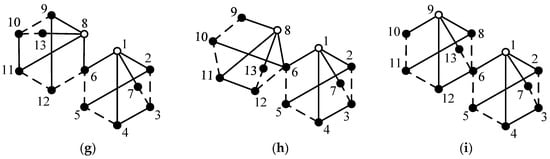
Figure 6.
Nine topological graphs of 11-link 2-DOF fractionated PGTs obtained by combining two PGT graphs in Figure 4c (a–i).
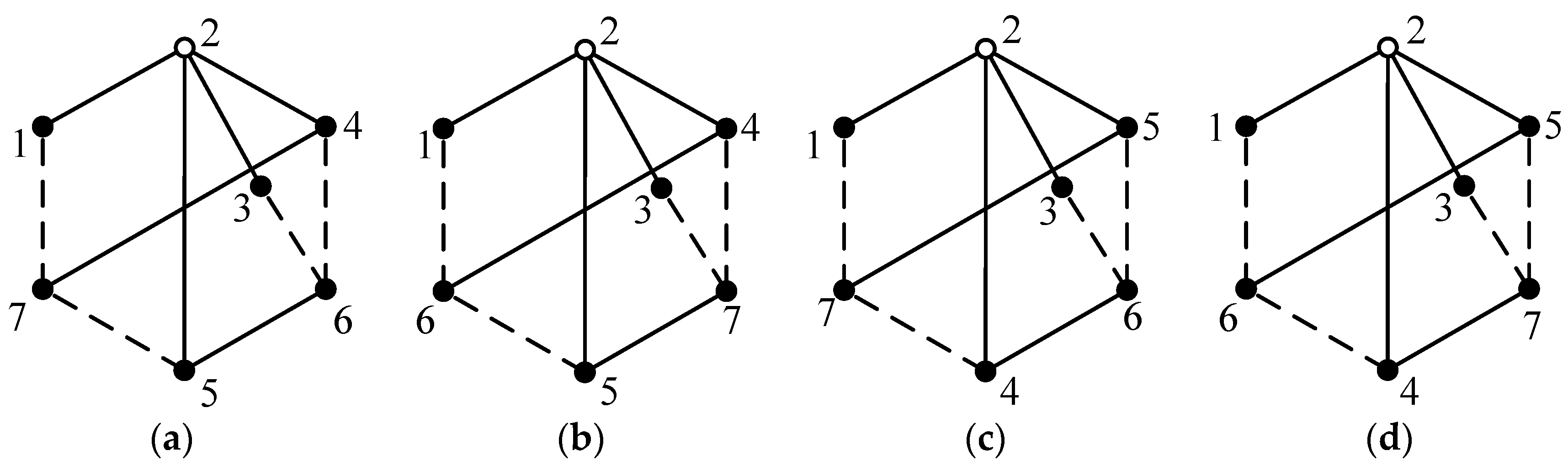
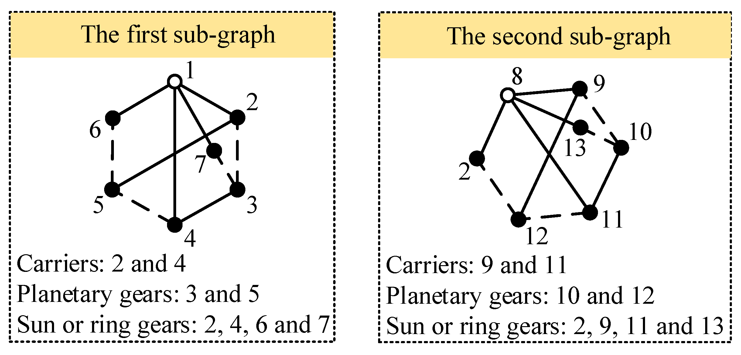
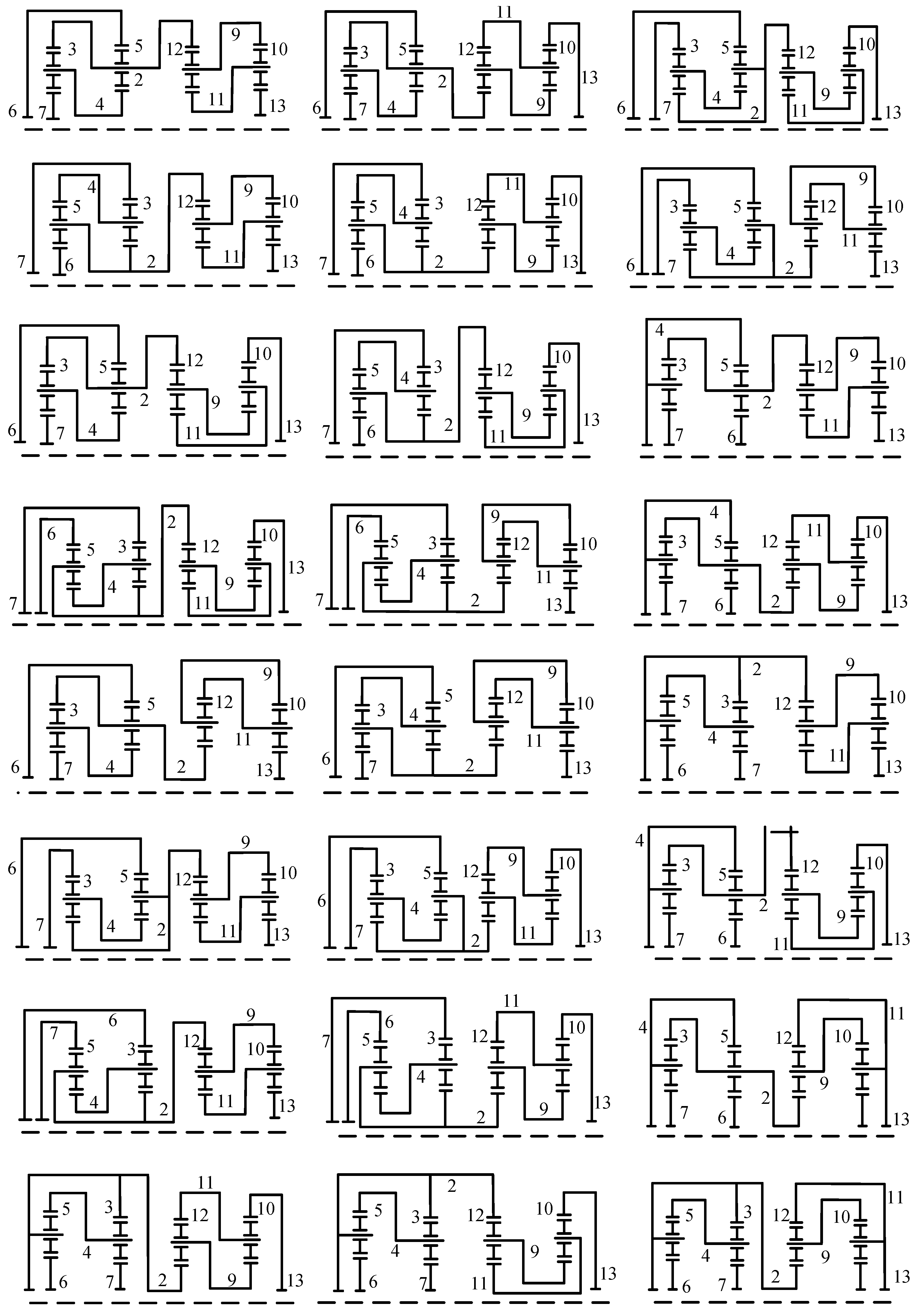
The process of sketching functional diagrams corresponding to a fractionated PGT graph is as follows. (a) A fractionated PGT graph can be separated into two independent sub-graphs. For each subgraph, carriers and planetary gears are determined based on the path of revolute edges. In a revolute edge path with the length of two, starting from the hollow vertex, the first solid vertex represents a carrier, and the second solid vertex represents a planetary gear on that carrier. A gear that meshes with the planetary gear is a ring gear or sun gear. (b) All possible functional diagrams of each subgraph of the PGT graph are sketched. (c) The link with the same label in the two separate functional diagrams is connected to obtain the functional diagrams of the fractionated PGT graph. For example, two subgraphs of the first PGT graph in Figure 6 are shown in Figure 7. In the first subgraph, the revolute edge paths with the length of two, starting from hollow vertex 1, are paths 1-2-5 and 1-4-3. For path 1-2-5, link 2 is identified as a carrier, link 5 is its corresponding planetary gear, and links 4 and 6 that mesh with link 5 are ring gears or sun gears. For path 1-4-3, link 4 is a carrier, link 3 is its corresponding planetary gear, and links 2 and 7 that mesh with link 3 are ring gears or sun gears. In the second subgraph, the revolute edge paths with the length of two, starting from hollow vertex 8, are paths 8-9-12 and 8-11-10. For path 8-9-12, link 9 is a carrier, link 12 is its corresponding planetary gear, links 2 and 11 that mesh with link 12 as ring gears or sun gears. For path 8-11-10, link 11 is a carrier, link 10 is its corresponding planetary gear, and links 9 and 13 that mesh with link 10 are ring gears or sun gears. By connecting the link with the same label (link 2) in the two separate sub-functional diagrams, all feasible functional diagrams corresponding to the first PGT graph in Figure 6 are obtained and shown in Figure 8.

Figure 7.
Subgraphs of the first PGT graph in Figure 6.

Figure 8.
All the functional diagrams corresponding to the first PGT graph in Figure 6.
3. Creative Design of 7-, 8- and 9-Speed AT Mechanisms
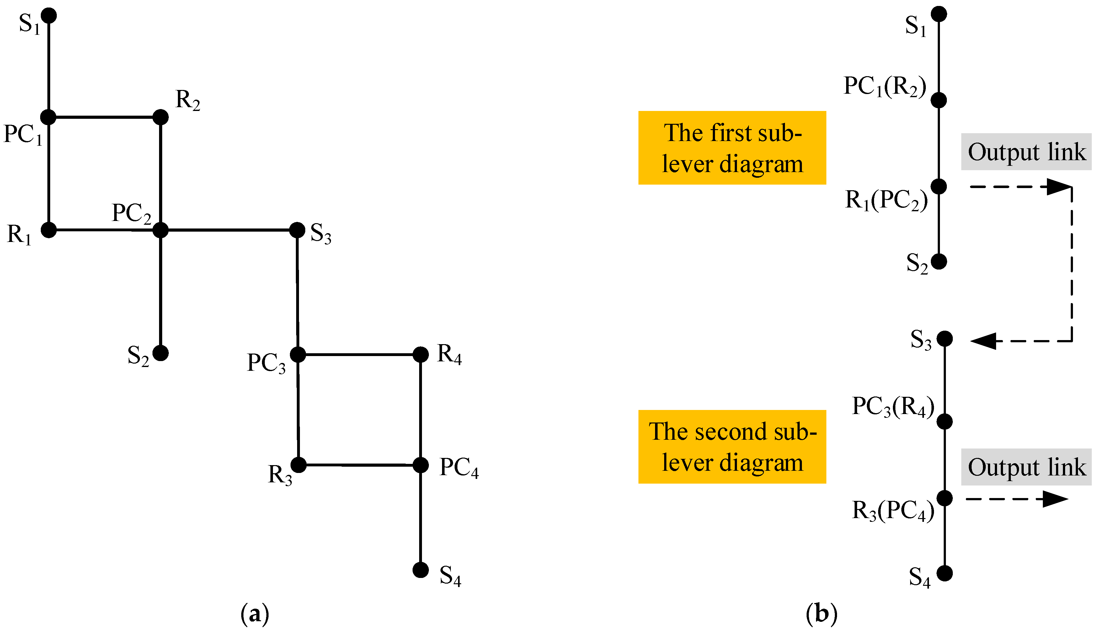
The lever diagram corresponding to a fractionated functional diagram contains two sub-lever diagrams. For example, the lever diagram corresponding to the first PGT functional diagram in Figure 8 is shown in Figure 9a, and the equivalent simplified lever diagram is shown in Figure 9b, where Sx, PCx and Rx (x =1, 2, 3, 4) represent the sun gear, planetary carrier and ring gear, respectively. Component R1 (PC2) is the output link of the first sub-lever diagram, and its output speed is passed into the second sub-lever diagram as the input speed. Component R3 (PC4) is selected as the output link of the second sub-lever diagram, namely, the output of the entire PGT lever diagram. Its speed is the output speed of the designed AT mechanism.

Figure 9.
Lever diagram corresponding to the first functional diagram in Figure 8 (a), and the equivalent simplified lever diagram (b).
Adding shifting control elements (clutches and brakes) to a PGT lever diagram enables the implementation of shifting function in an AT, allowing for the design of the transmission mechanism. The arrangement of shifting control elements should comply with the following rules: (1) The output shaft is typically directly connected to the carrier or the ring gear, rather than being connected to the sun gear, because the sun gear has a lower output torque. (2) The number of control elements is generally kept to a maximum of six, as having too many control elements would result in an excessively large size for the AT. (3) Clutches are typically arranged between the input shaft and the components of the PGT. (4) Brakes should not be placed on the output components. (5) To reduce the complexity of shifting, during gear changes, only one control element undergoes a change in its operational state. (6) The AT mechanism can achieve multiple forward gears and one reverse gear. (7) After completing the arrangement of control components, it is necessary to determine whether there will be interference among the components. Configurations that cause interference will increase the manufacturing difficulty of the AT and should be eliminated.
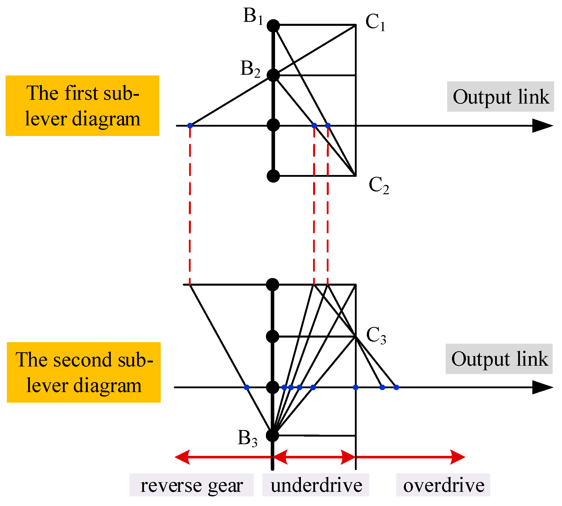
By determining reasonable arrangement schemes of control elements (clutches and brakes) in the functional diagram of PGTs, the design of AT mechanisms can be completed. For example, when using the lever diagram of PGT in Figure 9 to design a 7-speed AT mechanism, the arrangement of control elements is shown in Figure 10, where B1, B2 and B3 represent brakes, and C1, C2 and C3 represent clutches. The derived new 7-speed AT mechanism is shown in Figure 11a. This mechanism can achieve seven forward gears (two overdrive gears, one direct gear and four underdrive gears) and one reverse gear. The characteristic parameter k of a planetary gear set is the tooth ratio between the ring gear and the sun gear, and its value should be between 1.4 and 4. The step ratio of two adjacent speed ratios should be between 1.1 and 1.8, that is, 1.1 ≤ ij/ij+1 ≤ 2.1, where ij represents the speed ratio of jth forward gear. In order to ensure reasonable speed ratios and step ratios of the AT mechanism, a traversal cycle can be implemented using MATLAB programming to determine appropriate value of the characteristic parameter k of each planetary gear set. For example, the characteristic parameters of the four planetary gear sets in Figure 9a are denoted as k1, k2, k3 and k4, respectively. According to Figure 10, the relationship between each speed ratio and the characteristic parameters for the mechanism in Figure 11a is shown in Table 2. The determined values for the characteristic parameters are k1 = 2.4, k2 = 2.55, k3 = 1.5 and k4 = 2.5. By substituting the values of characteristic parameters into the speed ratio expressions in Table 2, the speed ratios of the seven forward gears and one reverse gear of the 7-speed AT mechanism in Figure 11a are determined as 7.1, 3.5, 2, 1.4, 1, 0.78, 0.68 and −4.8, respectively. The speed ratio of each gear in Figure 11a and the operating mode of control elements are shown in Table 3. The speed ratios of the underdrive gears of this AT mechanism are relatively large. Therefore, this AT mechanism can provide a larger output torque during the vehicle’s startup phase, which is suitable for heavy-duty vehicles.

Figure 10.
Arrangement of control elements.

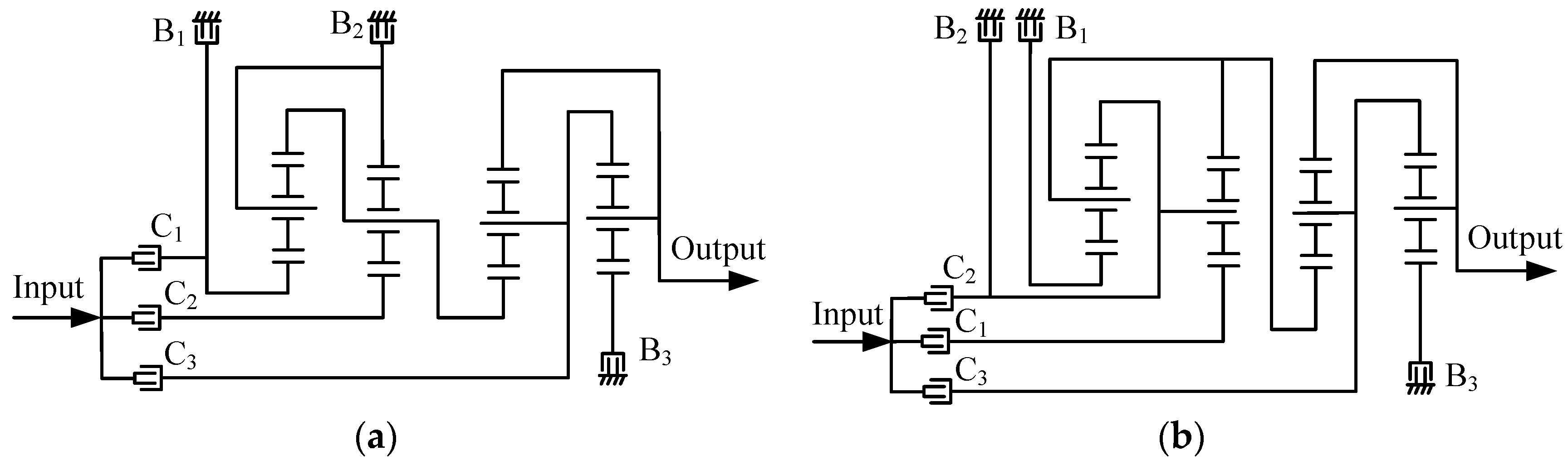
Figure 11.
The first (a) and second (b) new 7-speed automatic transmissions.
Table 2.
Relationship between each speed ratio and characteristic parameters in Figure 11a.
Table 3.
Speed ratios and the operating mode of control elements of the AT mechanism in Figure 11a.
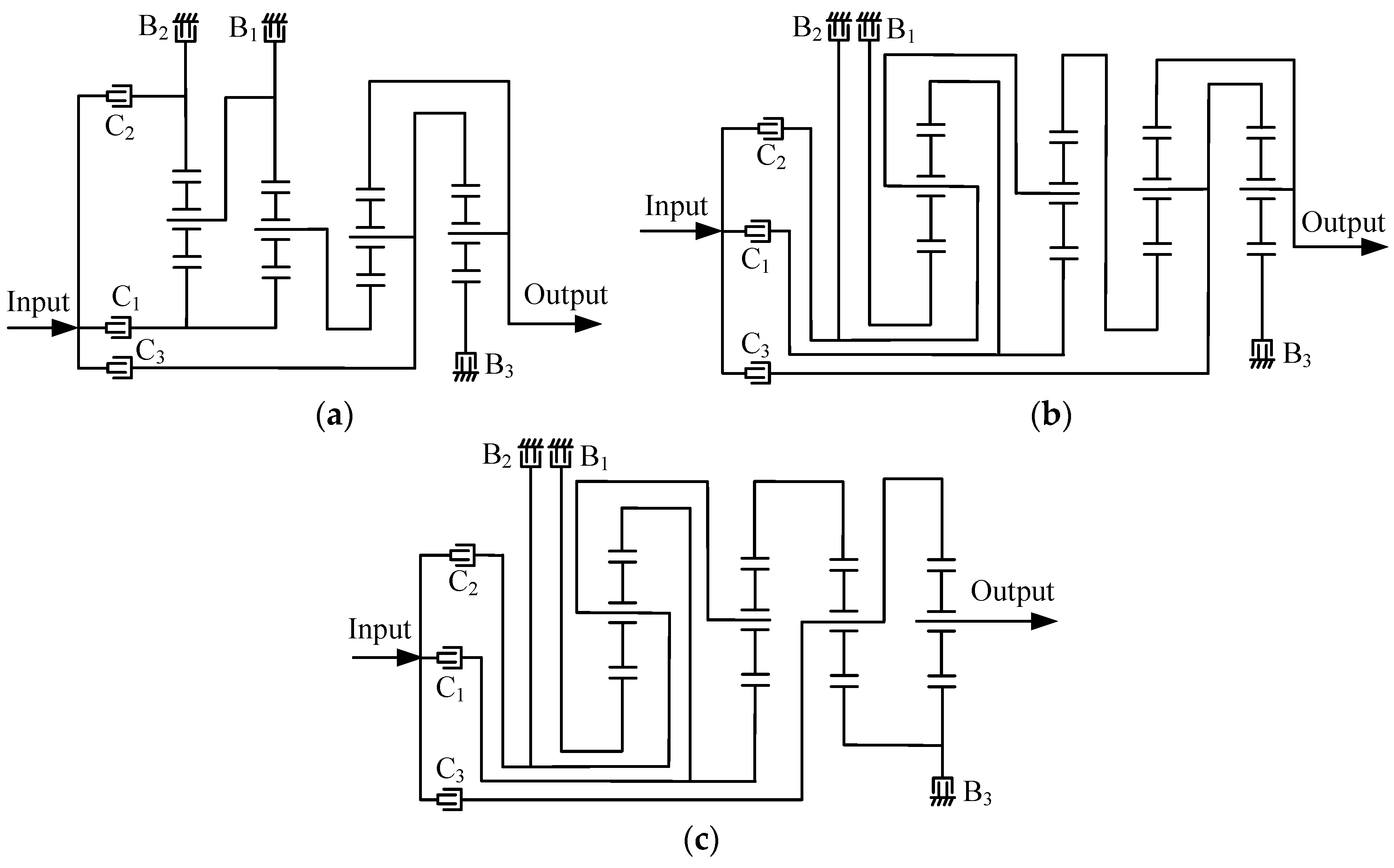
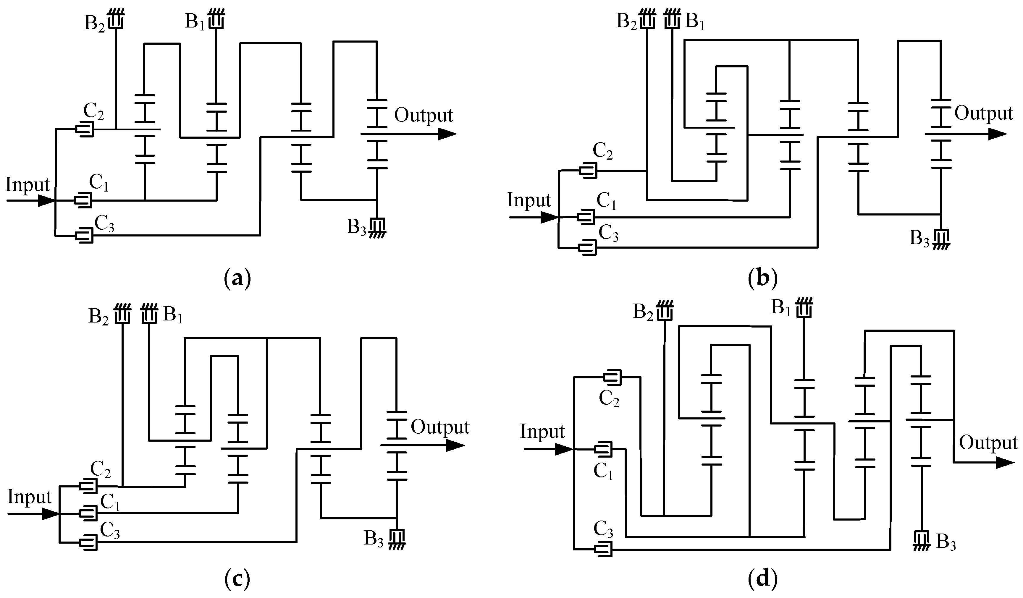
By applying the aforementioned method and considering all the synthesized 11-link 2-DOF fractionated PGT graphs, it is possible to design all feasible configurations of 7-speed, 8-speed and 9-speed AT mechanisms. Furthermore, from these AT mechanisms, it is possible to select novel configurations that possess reasonable speed ratios and step ratios. For example, another novel 7-speed AT mechanism is shown in Figure 11b, three novel 8-speed AT mechanisms are shown in Figure 12 and four novel 9-speed AT mechanisms are shown in Figure 13. The speed ratios and the operating mode of control elements for these mechanisms are provided in Table A1, Table A2, Table A3, Table A4, Table A5, Table A6, Table A7 and Table A8 in Appendix A.

Figure 12.
The first (a), second (b) and third (c) new 8-speed AT mechanisms.

Figure 13.
The first (a), second (b), third (c) and fourth (d) new 9-speed AT mechanisms.
4. Performance Analysis and Simulation of AT Mechanism
Performance analysis and simulation can be used to evaluate the performances of AT mechanisms, making it easier to select mechanism configurations with excellent performances from a large number of designed AT mechanisms. This section considers the 9-speed AT mechanism shown in Figure 13a as an example to study the kinematic analysis, torque analysis, power flow analysis, efficiency analysis and simulation of the AT mechanism.
4.1. Kinematic Analysis
Kinematic analysis aims to use matrix method to determine the speed ratio of each gear of an AT mechanism. The lever diagram in Section 3 is simple and intuitive for calculating speed ratios, but it is not convenient for computer automation and has lower efficiency. The matrix method can be automated with the help of a computer, making it suitable for fast calculation of speed ratios of AT mechanisms in large quantities.
The characteristic parameter k of a planetary gear set is the tooth ratio between the ring gear and the sun gear. In the absence of power losses, the relationship between the speeds of the sun gear, the planetary carrier and the ring gear is described by the following equation.
where , and represent the speeds of the sun gear, ring gear and planetary carrier, respectively. For an AT mechanism with m planetary gear sets, the speed relationships between all sun gears, planetary carriers and ring gears are described by the following Equation (7).
where , and represent the speeds of the sun gear, planetary carrier and ring gear, respectively, in the xth planetary gear set.
In an AT mechanism, the components that connect different planetary gear sets have the same speed. Considering Figure 13a, for instance, the sun gear of the first planetary gear set and the sun gear of the second planetary gear set are fixed together as one component. Therefore, their speeds are the same, i.e., . Additionally, the ring gear of the first planetary gear set, the planetary carrier of the second planetary gear set and the ring gear of the third planetary gear set are fixed together as one component. Therefore, their speeds are the same, i.e., = . Similarly, based on the connection between the third and fourth planetary gear sets, we have and . The relationships between components having equal speeds are shown in Equation (8).
When the AT mechanism is in operation, the constraint equations of component speeds can be obtained based on the control elements involved in the work. If the input speed is assumed to be unit 1, then the component connected to the housing has a speed of 0, and the component connected to the input shaft has a speed of 1. When the clutch is in the engaged state, the components connected to both ends of the clutch are joined together and have the same rotational speed. When the brake is engaged, the involved link is connected to the transmission housing, unable to rotate, and in a braking state with a speed of 0.
For example, when the mechanism in Figure 13a works at the 1st gear, clutch C1 and brakes B1 and B3 are engaged. The sun gear of the first planetary gear set is connected to the input shaft and has a speed of 1. The ring gear of the second planetary gear set, and the sun gear of the fourth planetary gear set are connected to the housing and have a speed of 0. Therefore, three speed constraint equations can be obtained as shown in Equation (9).
The above equations can be written in matrix form as shown in Equation (10) for ease of computer processing. In this form, K is the coefficient matrix of characteristic parameters for kinematic analysis, and P is a constant vector, as shown in Equation (11). W represents the velocity vector, i.e., [, , , , , , , , , , , ]T.
By solving the velocity matrix equation in Equation (10), the absolute velocities of each component can be obtained. The speed ratio of each gear is referred to as the speed ratio between the input and output components, as shown in the following Equation (12).
where ig is the speed ratio of the gth gear, is the input shaft speed, assumed to be unit 1, and is the output shaft speed. For example, the relationship between each speed ratio and the characteristic parameters, and the values of speed ratios of the mechanism in Figure 13a are obtained and shown in Table 4. Values of four characteristic parameters are k1 = 2, k2 = 1.5, k3 = 2.3 and k4 = 2.5, respectively. The calculated speed ratios yield the same results as those obtained using the lever method in Section 3.
Table 4.
Speed ratios of the mechanism in Figure 13a.
4.2. Torque Analysis
In the absence of energy losses, the following torque balance equation exists between the sun gear, planetary carrier and ring gear in each planetary gear set in a stable state.
where is the characteristic parameter of the planetary gear set, and , and represent the torques on the sun gear, ring gear and planetary carrier, respectively, within the planetary gear set.
For an AT mechanism with m planetary gear sets, there are the following 2m torque equations.
where is the characteristic parameter of the xth planetary gear set, and , and represent the torques on the sun gear, ring gear and planetary carrier of the xth planetary gear set, respectively.
Additionally, the brakes in the engaged state will provide the corresponding torque constraint equations. In the absence of torque losses, the input torque, output torque and brake torque have the following relationship.
where is the input torque (the sum of torques of components connected to the input shaft), is the output torque, is the brake torque (the sum of torques of components connected to engaged brakes), and ig is the speed ratio of the gth gear. Assuming is 1, the equation regarding and derived from Equation (15) is as follows.
For example, when the mechanism in Figure 13a works at the 1st gear, clutch C1 and brakes B1 and B3 are engaged. The sun gears of the first and second planetary gear sets are connected to the input shaft. The ring gear of the second planetary gear set, and the sun gears of the third and fourth planetary gear sets are connected to the housing. According to Equation (16), the derived torque constraint equation is shown as follows.
For an AT mechanism with m planetary gear sets, a total of 3m independent equations are required to determine the torque solution. For the mechanism in Figure 13a with m = 4 planetary gear sets, a total of 12 independent equations are needed. In addition to the 10 equations that can be obtained from Equations (14) and (17), two additional independent equations are still required. In the transmission process of an AT mechanism, the components that are not subject to external forces have a torque of 0. When the mechanism in Figure 13a works at the 1st gear, the torque of the component consisting of the ring gear of the first planetary gear set, the carrier of the second planetary gear set, and the ring gear of the third planetary gear set is 0. Additionally, the torque of the component consisting of the carrier of the third planetary gear set and the ring gear of the fourth planetary gear set is 0. Therefore, two independent equations can be obtained, as shown in Equation (18).
The above Equations (14), (17) and (18) can be written in the matrix form in Equation (19) for ease of computer processing. In this form, M is the coefficient matrix of characteristic parameters for torque analysis, and D is a constant vector, as shown in Equation (20). T represents the torque vector, i.e., [, , , , , , , , , , , ]T.
Solving the torque matrix equation in Equation (20) allows us to obtain the torques of all components, including the output component. Assume that the input torque is = 1, the torques of the output component for 1st to 9th gears of the mechanism in Figure 13a are −5.0217, −3.013, −2.0087, −1.4, −1, −0.8203, −0.7172, −0.6034 and −0.5036, respectively. The torque for the reverse gear is 4.0173.
4.3. Power Flow Analysis
The power flow analysis aims to obtain the power values and directions transmitted by the components in different gears during operation and analyze the presence of cyclic power. For the power flow of a gear, if the sum of power flowing into a component is greater than one, or the sum of power flowing out of a component is greater than one, then there is cyclic power in the power flow of that gear. In the AT mechanism, excessive cyclic power will increase the loss of transmission efficiency and component wear. Based on the kinematic and torque analyses, the speeds and torques of each component in different gears can be obtained and multiplying them yields the power transmitted by the components, as shown in the following equation.
where and are the speed and torque of component i, and represents the power flowing through component i. The power direction is determined by the following rules.
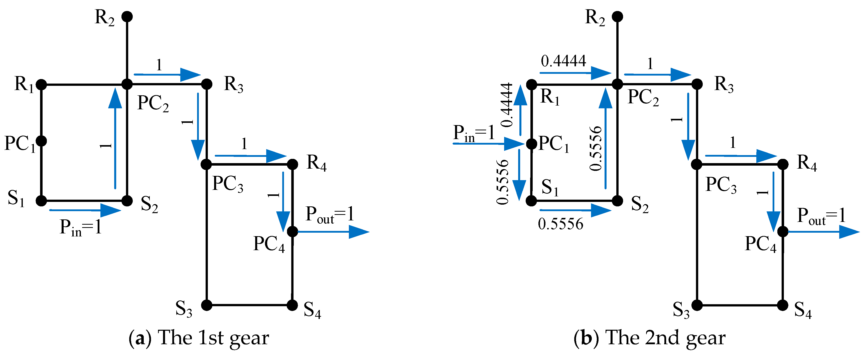
The calculated power values here represent the theoretical powers without losses. For example, the power flowing through each component for different gears of the AT mechanism in Figure 13a is shown in Table 5. When this AT mechanism works at the 3rd gear, there is power circulation in the first planetary gear set. However, the value 1.5 of power circulation is relatively small, resulting in less efficiency loss; hence, the configuration of this mechanism is still feasible. Under the working conditions of the 5th gear in direct drive, clutches C1, C2 and C3 are engaged simultaneously, driving the AT mechanism to rotate as a whole and directly transmitting power to the output shaft. Therefore, there is no power flow within the four planetary gear sets, so the fifth gear in direct drive is not included in Table 5. According to the power values in Table 5, the power flow diagram for each gear can be sketched. For instance, in the lever diagram corresponding to the AT mechanism in Figure 13a, the power flow diagrams for the 1st and 2nd gears are shown in Figure 14.
Table 5.
Power flowing through each component for different gears of the AT mechanism in Figure 13a.
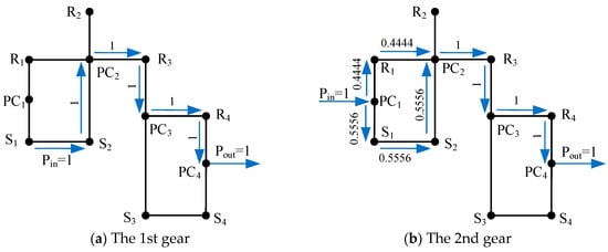
Figure 14.
Power flow diagrams for the 1st (a) and 2nd (b) gears of the AT mechanism in Figure 13a.
4.4. Efficiency Analysis
Transmission efficiency is an important parameter for evaluating the performance of an AT mechanism. Assuming that gear meshing loss is the only energy loss in the AT mechanism, and the torque loss at the gear meshing point is caused by gear friction. The torque method can be used to estimate the transmission efficiency. The calculation equation is as follows.
where represents the transmission efficiency of the AT mechanism, and is the theoretical speed ratio of a gear, which is a function of m characteristic parameters. And represents the actual speed ratio, where is the transmission efficiency with a value of 0.9702 when the planetary carrier of a planetary gear set is fixed (assuming a transmission efficiency of 0.98 between the sun gear and the planetary gear, and a transmission efficiency of 0.99 between the ring gear and the planetary gear). The value of is related to the power flow direction in the planetary gear set, which can be calculated using Equation (24). The specific determination rules are shown in Equation (25).
The transmission efficiency of each gear for a reasonable AT mechanism should be greater than 0.9. According to Equations (23)–(25), the transmission efficiencies for the 1st to 9th gears of the AT mechanism in Figure 13a are obtained as 0.965, 0.9664, 0.9825, 0.9915, 1, 0.9843, 0.9817, 0.9794 and 0.9692, respectively. The transmission efficiency for the reverse gear is 0.9533.
4.5. AMESim Simulation
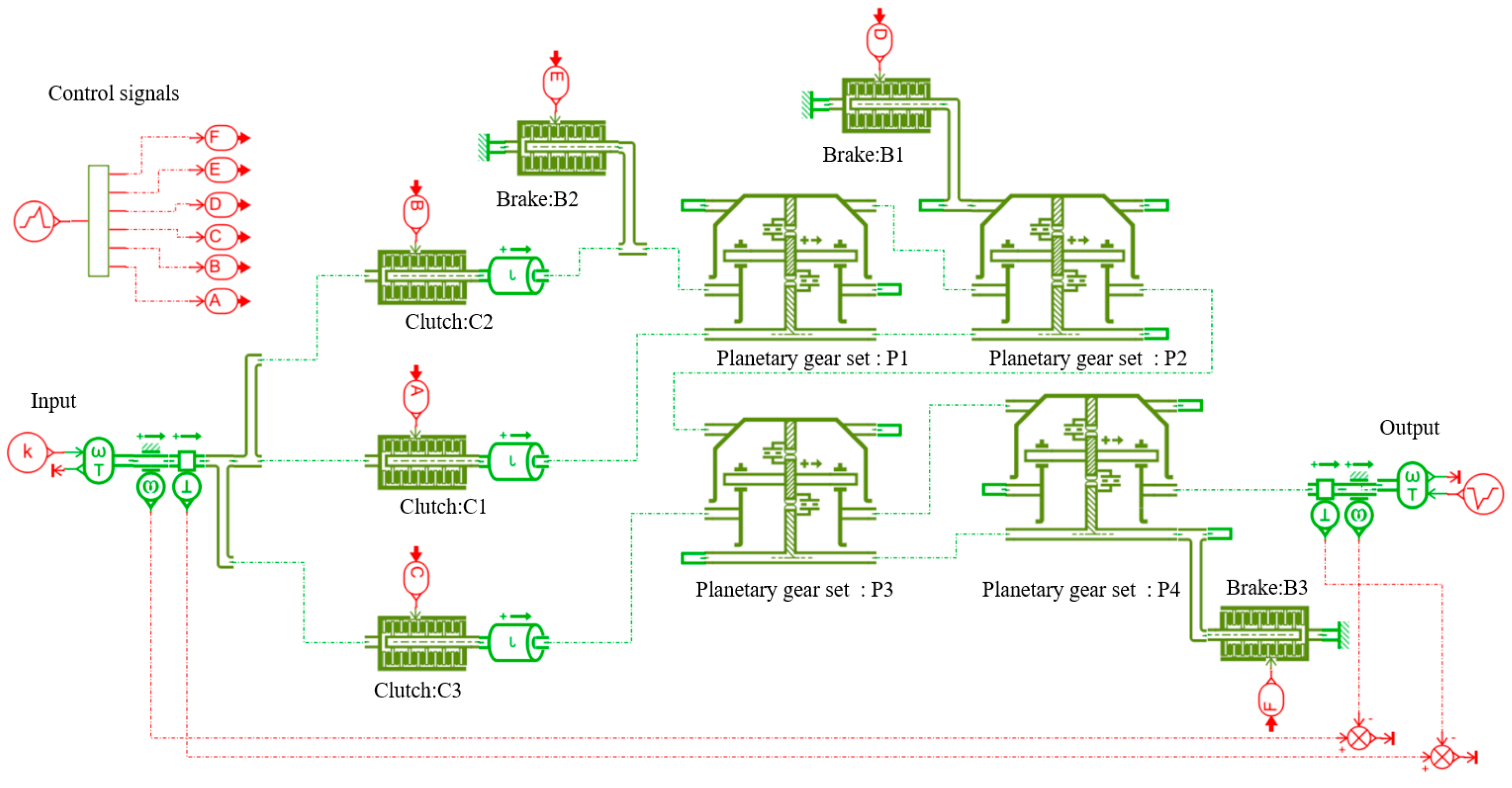
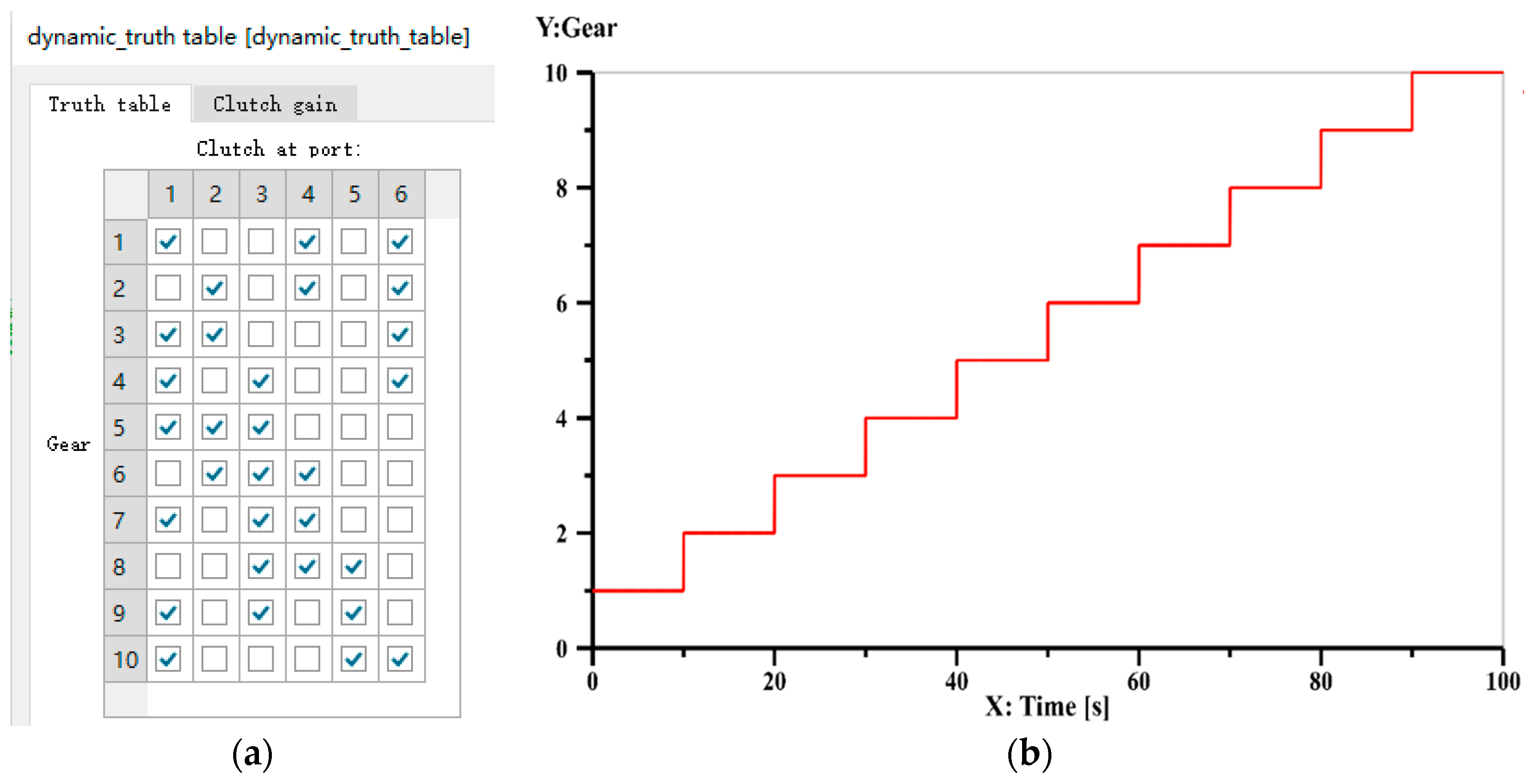
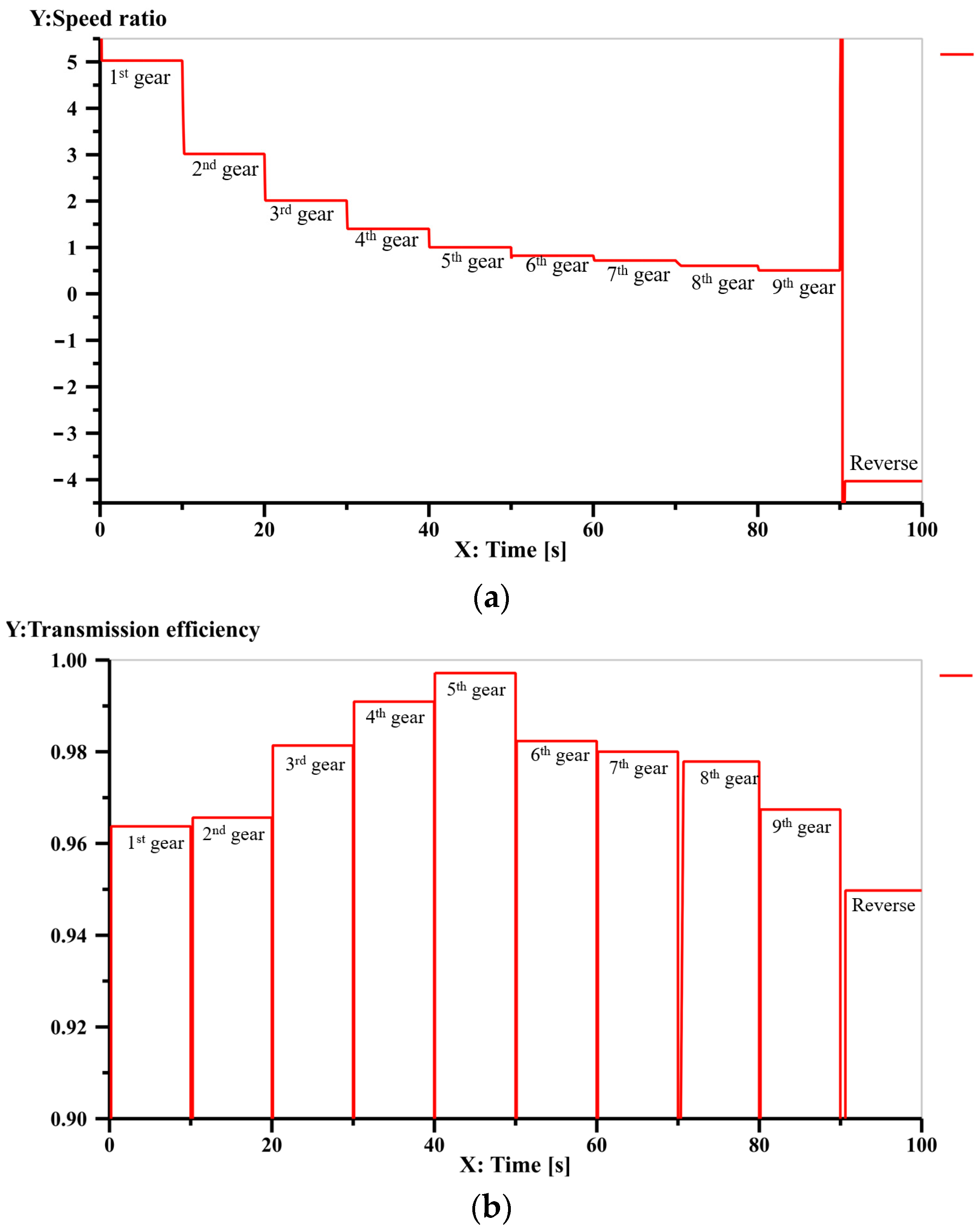
The simulation model of the 9-speed AT mechanism shown in Figure 13a, established using the AMESim software, is depicted in Figure 15. The simulation model consists of an input shaft, an output shaft, four planetary gear sets, three clutches and three brakes. In this model, clutches C1, C2 and C3 are represented by letters A, B and C, respectively, and brakes B1, B2 and B3 are represented by letters D, E and F, respectively. According to the operating mode of control elements in Table A5 of Appendix A, the signals in AMESim that can achieve each gear are set as shown in Figure 16a. Control elements C1, C2, C3, B1, B2 and B3 are numbered from 1 to 6. For example, the engaged control elements for the 1st gear in Figure 16a are elements 1, 4 and 6, which correspond to control elements C1, B1 and B3. In the simulation model, the input shaft is given a constant signal, setting the speed to a constant value of 300 r/min. And the output shaft is also given a constant signal, setting the load to a constant value of 100 N m. The forward gear direction is considered positive, and the reverse gear direction is considered negative. The total simulation time in AMESim is set to 100 s, with the following subdivisions: 0~10 s for the 1st gear, 10~20 s for the 2nd gear, 20~30 s for the 3rd gear, 30~40 s for the 4th gear, 40~50 s for the 5th gear, 50~60 s for the 6th gear, 60~70 s for the 7th gear, 70~80 s for the 8th gear, 80~90 s for the 9th gear, and 90~100 s for the 10th gear (reverse gear). The duration of each gear is set as shown in Figure 16b.
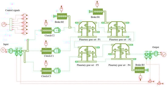
Figure 15.
AMESim simulation model of Figure 13a.
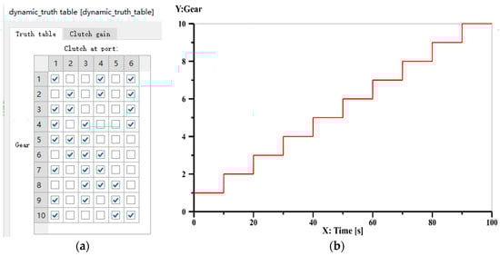
Figure 16.
Setting of control element signals (a) and the operating time (b) for each gear of Figure 13a.
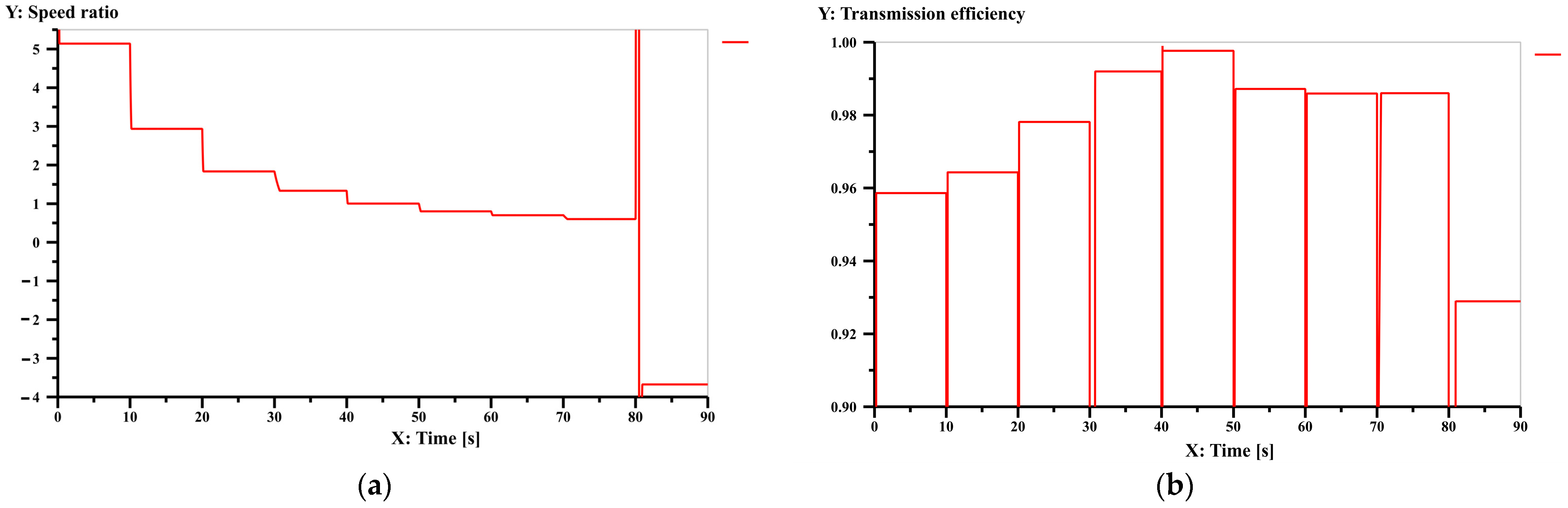
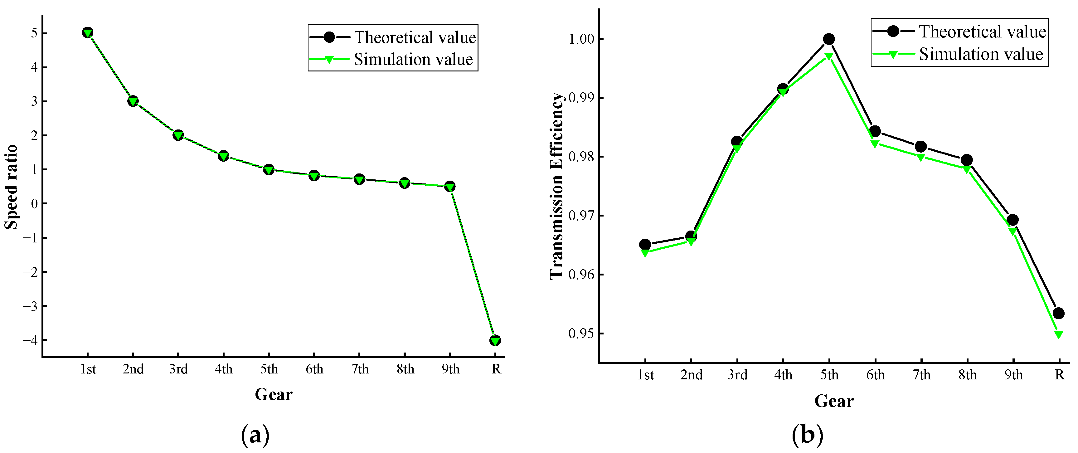
The simulation results of speed ratios of the 9-speed automatic transmission mechanism in Figure 13a are shown in Figure 17a, and the simulation results of the transmission efficiency are shown in Figure 17b. The comparison between the theoretical and simulated values of speed ratios and transmission efficiencies are shown in Table 6. The comparison line charts between the theoretical and simulated values are shown in Figure 18. Analysis reveals that the maximum error between the theoretical and simulated values is 0.37%, confirming the accuracy of the calculated results in this paper.

Figure 17.
Simulation result of speed ratio (a) and transmission efficiency (b) for each gear of Figure 13a.
Table 6.
Comparison between theoretical values and simulated values.
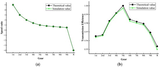
Figure 18.
The comparison line charts between theoretical values and simulated values of speed ratios (a) and transmission efficiencies (b).
The performance analysis and simulation methods mentioned above are applicable to all AT mechanisms. For example, the simulation model and results of the 7-speed AT mechanism in Figure 11a are shown in Figure A1 and Figure A2, respectively, in Appendix B; and the simulation model and results of the 8-speed AT mechanism in Figure 12a are shown in Figure A3 and Figure A4, respectively, in Appendix B. The results indicate that the nine new types of AT mechanisms shown in Figure 11, Figure 12 and Figure 13 possess reasonable speed ratios and step ratios and high transmission efficiencies.
5. Conclusions
Designing new mechanisms is the source and foundation for developing new ATs. This paper proposes an innovative design method for 7-speed, 8-speed and 9-speed AT mechanisms based on fractionated PGTs and investigates the performance analysis of the AT mechanisms.
The topological structure of PGT is crucial to the performance of AT mechanism. A method for the topological synthesis of 11-link 2-DOF fractionated PGTs is proposed, and those PGTs suitable for the design of AT mechanisms are determined. Then, based on the functional diagrams of PGTs, the innovative design of 7-speed, 8-speed and 9-speed AT mechanisms is explored, leading to the discovery of two novel 7-speed AT mechanisms, three novel 8-speed AT mechanisms and four novel 9-speed AT mechanisms. Among them, one 7-speed AT mechanism is found to be suitable for heavy-duty vehicles. Finally, the performance analyses of kinematics, torque, power flow and transmission efficiency of the AT mechanisms are conducted, and AMESim software is utilized to simulate speed ratios and transmission efficiencies of the AT mechanisms.
The comparison between the simulation results and the obtained theoretical values validates the accuracy of the calculation results. The analysis and simulation results indicate that the nine novel AT mechanisms obtained in this study all possess reasonable speed ratios and step ratios and high transmission efficiencies. Additionally, these mechanisms do not exhibit any cyclic power, or the cyclic power values are within an acceptable limit.
Author Contributions
Conceptualization, W.Y.; methodology, W.Y.; software, X.X.; validation, W.Y.; formal analysis, W.Y.; investigation, W.Y.; resources, W.Y.; data curation, X.X.; writing—original draft preparation, X.X.; writing—review and editing, W.Y.; visualization, W.Y.; supervision, W.Y.; project administration, W.Y.; funding acquisition, W.Y. All authors have read and agreed to the published version of the manuscript.
Funding
The authors are grateful to the projects supported by the National Natural Science Foundation of China (No. 52205036) and the Fundamental Research Funds for the Central Universities, China University of Geosciences (Wuhan) (No. 120-162301212701).
Data Availability Statement
Not applicable.
Acknowledgments
Thanks to the anonymous reviewers for their valuable suggestions for revision.
Conflicts of Interest
The authors declare no conflict of interest.
Appendix A
Table A1.
Speed ratios and the operating mode of control elements of the AT mechanism in Figure 11b.
Table A1.
Speed ratios and the operating mode of control elements of the AT mechanism in Figure 11b.
| Gear | Property of Gear | Operating Clutches | Operating Brakes | Speed Ratio | Step Ratio |
|---|---|---|---|---|---|
| 1st gear | underdrive gear | C1 | B1, B3 | 5 | - |
| 2nd gear | underdrive gear | C2 | B1, B3 | 3 | 1.67 |
| 3rd gear | underdrive gear | C1, C2 | B3 | 2 | 1.5 |
| 4th gear | underdrive gear | C1, C3 | B3 | 1.3125 | 1.5238 |
| 5th gear | direct gear | C1, C2, C3 | - | 1 | 1.3125 |
| 6th gear | overdrive gear | C2, C3 | B1 | 0.8684 | 1.1515 |
| 7th gear | overdrive gear | C1, C3 | B1 | 0.7857 | 1.1053 |
| reverse gear | reverse gear | C1 | B2, B3 | −4 | - |
Values of four characteristic parameters are k1 = 2, k2 = 2, k3 = 2.2 and k4 = 3.2.
Table A2.
Speed ratios and the operating mode of control elements of the AT mechanism in Figure 12a.
Table A2.
Speed ratios and the operating mode of control elements of the AT mechanism in Figure 12a.
| Gear | Property of Gear | Operating Clutches | Operating Brakes | Speed Ratio | Step Ratio |
|---|---|---|---|---|---|
| 1st gear | underdrive gear | C1 | B1, B3 | 5.1 | - |
| 2nd gear | underdrive gear | C1 | B2, B3 | 2.9 | 1.76 |
| 3rd gear | underdrive gear | C1, C2 | B3 | 1.8 | 1.61 |
| 4th gear | underdrive gear | C1, C3 | B3 | 1.3 | 1.38 |
| 5th gear | direct gear | C1, C2, C3 | - | 1 | 1.3 |
| 6th gear | overdrive gear | C1, C3 | B2 | 0.8 | 1.25 |
| 7th gear | overdrive gear | C1, C3 | B1 | 0.7 | 1.14 |
| 8th gear | overdrive gear | C3 | B1, B2 | 0.6 | 1.17 |
| reverse gear | reverse gear | C2 | B1, B3 | −3.7 | - |
Values of four characteristic parameters are k1 = 1.4, k2 = 1.8, k3 = 1.5 and k4 = 3.
Table A3.
Speed ratios and the operating mode of control elements of the AT mechanism in Figure 12b.
Table A3.
Speed ratios and the operating mode of control elements of the AT mechanism in Figure 12b.
| Gear | Property of Gear | Operating Clutches | Operating Brakes | Speed Ratio | Step Ratio |
|---|---|---|---|---|---|
| 1st gear | underdrive gear | C1 | B1, B3 | 5 | - |
| 2nd gear | underdrive gear | C2 | B1, B3 | 3 | 1.67 |
| 3rd gear | underdrive gear | C1, C2 | B3 | 2 | 1.5 |
| 4th gear | underdrive gear | C1, C3 | B3 | 1.4 | 1.43 |
| 5th gear | direct gear | C1, C2, C3 | - | 1 | 1.4 |
| 6th gear | overdrive gear | C2, C3 | B1 | 0.82 | 1.22 |
| 7th gear | overdrive gear | C1, C3 | B1 | 0.71 | 1.15 |
| 8th gear | overdrive gear | C3 | B1, B2 | 0.6 | 1.18 |
| reverse gear | reverse gear | C1 | B2, B3 | −4 | - |
Values of four characteristic parameters are k1 = 1.5, k2 = 2.0, k3 = 1.5 and k4 = 2.5.
Table A4.
Speed ratios and the operating mode of control elements of the AT mechanism in Figure 12c.
Table A4.
Speed ratios and the operating mode of control elements of the AT mechanism in Figure 12c.
| Gear | Property of Gear | Operating Clutches | Operating Brakes | Speed Ratio | Step Ratio |
|---|---|---|---|---|---|
| 1st gear | underdrive gear | C1 | B1, B3 | 4.9 | - |
| 2nd gear | underdrive gear | C2 | B1, B3 | 2.94 | 1.67 |
| 3rd gear | underdrive gear | C1, C2 | B3 | 1.96 | 1.5 |
| 4th gear | underdrive gear | C1, C3 | B3 | 1.38 | 1.42 |
| 5th gear | direct gear | C1, C2, C3 | - | 1 | 1.38 |
| 6th gear | overdrive gear | C2, C3 | B1 | 0.82 | 1.22 |
| 7th gear | overdrive gear | C1, C3 | B1 | 0.71 | 1.15 |
| 8th gear | overdrive gear | C3 | B1, B2 | 0.6 | 1.18 |
| reverse gear | reverse gear | C1 | B2, B3 | −3.92 | - |
Values of four characteristic parameters are k1 = 1.5, k2 = 2.0, k3 = 2.4 and k4 = 2.6.
Table A5.
Speed ratios and the operating mode of control elements of the AT mechanism in Figure 13a.
Table A5.
Speed ratios and the operating mode of control elements of the AT mechanism in Figure 13a.
| Gear | Property of Gear | Operating Clutches | Operating Brakes | Speed Ratio | Step Ratio |
|---|---|---|---|---|---|
| 1st gear | underdrive gear | C1 | B1, B3 | 5.0217 | - |
| 2nd gear | underdrive gear | C2 | B1, B3 | 3.013 | 1.67 |
| 3rd gear | underdrive gear | C1, C2 | B3 | 2.0087 | 1.5 |
| 4th gear | underdrive gear | C1, C3 | B3 | 1.4 | 1.43 |
| 5th gear | direct gear | C1, C2, C3 | - | 1 | 1.4 |
| 6th gear | overdrive gear | C2, C3 | B1 | 0.8203 | 1.22 |
| 7th gear | overdrive gear | C1, C3 | B1 | 0.7172 | 1.15 |
| 8th gear | overdrive gear | C3 | B1, B2 | 0.6034 | 1.18 |
| 9th gear | overdrive gear | C1, C3 | B2 | 0.5036 | 1.2 |
| reverse gear | reverse gear | C1 | B2, B3 | −4.0173 | - |
Values of four characteristic parameters are k1 = 2, k2 = 1.5, k3 = 2.3 and k4 = 2.5.
Table A6.
Speed ratios and the operating mode of control elements of the AT mechanism in Figure 13b.
Table A6.
Speed ratios and the operating mode of control elements of the AT mechanism in Figure 13b.
| Gear | Property of Gear | Operating Clutches | Operating Brakes | Speed Ratio | Step Ratio |
|---|---|---|---|---|---|
| 1st gear | underdrive gear | C1 | B1, B3 | 5.0105 | - |
| 2nd gear | underdrive gear | C2 | B1, B3 | 3.5924 | 1.3947 |
| 3rd gear | underdrive gear | C1, C2 | B3 | 2.6471 | 1.3571 |
| 4th gear | underdrive gear | C1, C3 | B3 | 1.2882 | 1.6667 |
| 5th gear | direct gear | C1, C2, C3 | - | 1 | 1.5880 |
| 6th gear | overdrive gear | C2, C3 | B1 | 0.8724 | 1.1462 |
| 7th gear | overdrive gear | C1, C3 | B1 | 0.7924 | 1.1011 |
| 8th gear | overdrive gear | C3 | B1, B2 | 0.6429 | 1.2326 |
| 9th gear | overdrive gear | C1, C3 | B2 | 0.5192 | 1.2381 |
| reverse gear | reverse gear | C1 | B2, B3 | −3.9706 | - |
Values of four characteristic parameters are k1 = 2.8, k2 = 1.5, k3 = 1.5 and k4 = 1.7.
Table A7.
Speed ratios and the operating mode of control elements of the AT mechanism in Figure 13c.
Table A7.
Speed ratios and the operating mode of control elements of the AT mechanism in Figure 13c.
| Gear | Property of Gear | Operating Clutches | Operating Brakes | Speed Ratio | Step Ratio |
|---|---|---|---|---|---|
| 1st gear | underdrive gear | C1 | B1, B3 | 4.9 | - |
| 2nd gear | underdrive gear | C1 | B2, B3 | 2.94 | 1.67 |
| 3rd gear | underdrive gear | C1, C2 | B3 | 1.96 | 1.5 |
| 4th gear | underdrive gear | C1, C3 | B3 | 1.4 | 1.4 |
| 5th gear | direct gear | C1, C2, C3 | - | 1 | 1.4 |
| 6th gear | overdrive gear | C1, C3 | B2 | 0.81 | 1.15 |
| 7th gear | overdrive gear | C1, C3 | B1 | 0.7 | 1.14 |
| 8th gear | overdrive gear | C3 | B1, B2 | 0.58 | 1.2 |
| 9th gear | overdrive gear | C2, C3 | B1 | 0.48 | 1.2 |
| reverse gear | reverse gear | C2 | B1, B3 | −3.92 | - |
Values of four characteristic parameters are k1 = 2, k2 = 1.5, k3 = 2.5 and k4 = 2.5.
Table A8.
Speed ratios and the operating mode of control elements of the AT mechanism in Figure 13d.
Table A8.
Speed ratios and the operating mode of control elements of the AT mechanism in Figure 13d.
| Gear | Property of Gear | Operating Clutches | Operating Brakes | Speed Ratio | Step Ratio |
|---|---|---|---|---|---|
| 1st gear | underdrive gear | C1 | B1, B3 | 4.90 | - |
| 2nd gear | underdrive gear | C1 | B2, B3 | 2.94 | 1.67 |
| 3rd gear | underdrive gear | C1, C2 | B3 | 1.96 | 1.5 |
| 4th gear | underdrive gear | C1, C3 | B3 | 1.4 | 1.4 |
| 5th gear | direct gear | C1, C2, C3 | - | 1 | 1.4 |
| 6th gear | overdrive gear | C1, C3 | B2 | 0.81 | 1.15 |
| 7th gear | overdrive gear | C1, C3 | B1 | 0.70 | 1.14 |
| 8th gear | overdrive gear | C3 | B1, B2 | 0.58 | 1.20 |
| 9th gear | overdrive gear | C2, C3 | B1 | 0.48 | 1.20 |
| reverse gear | reverse gear | C2 | B1, B3 | −3.92 | - |
Values of four characteristic parameters are k1 = 2.0, k2 = 1.5, k3 = 1.4 and k4 = 2.5.
Appendix B
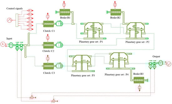
Figure A1.
AMESim simulation model of Figure 11a.
Figure A1.
AMESim simulation model of Figure 11a.
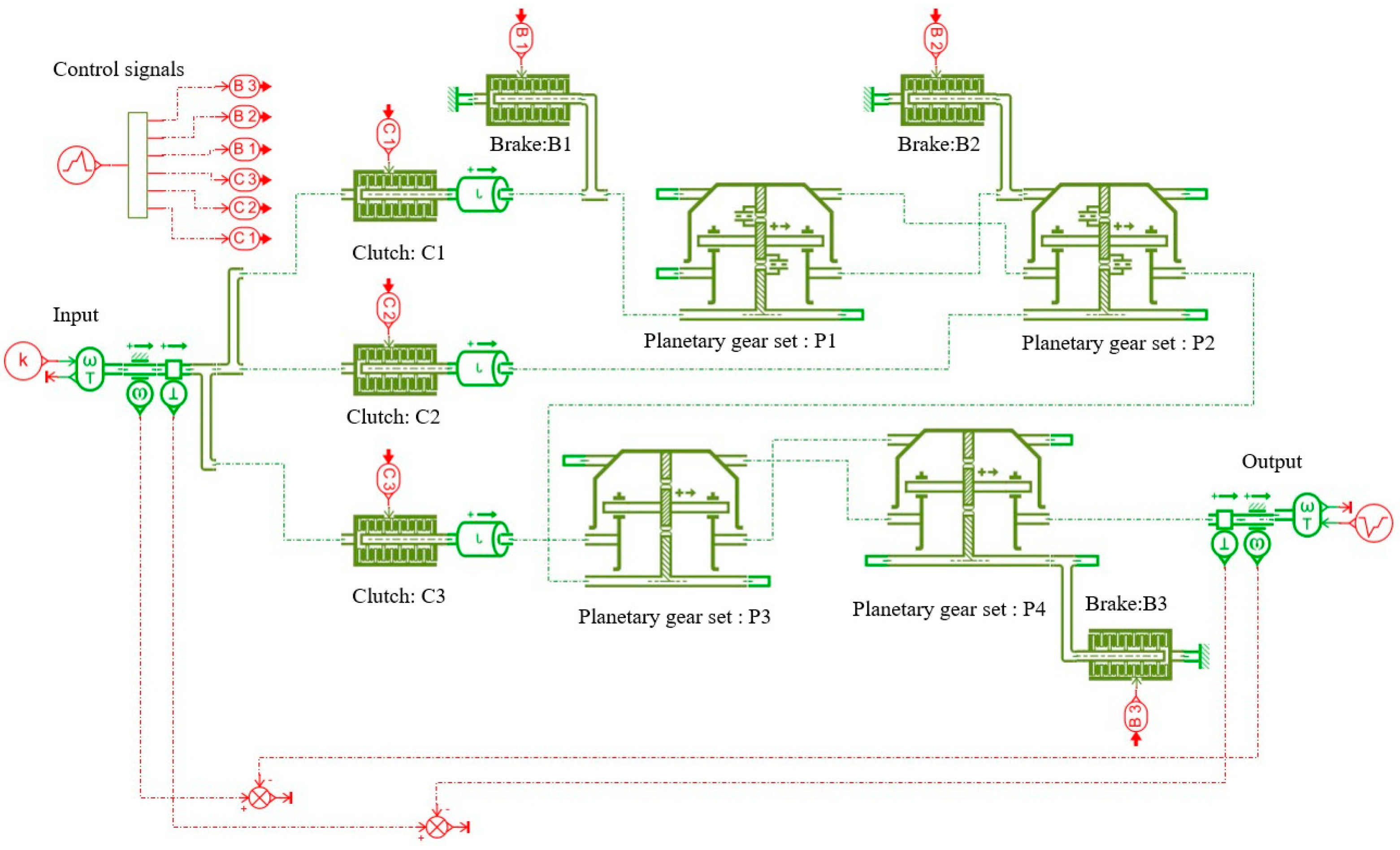
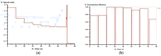
Figure A2.
Simulation result of speed ratio (a) and transmission efficiency (b) for each gear of Figure 11a.
Figure A2.
Simulation result of speed ratio (a) and transmission efficiency (b) for each gear of Figure 11a.
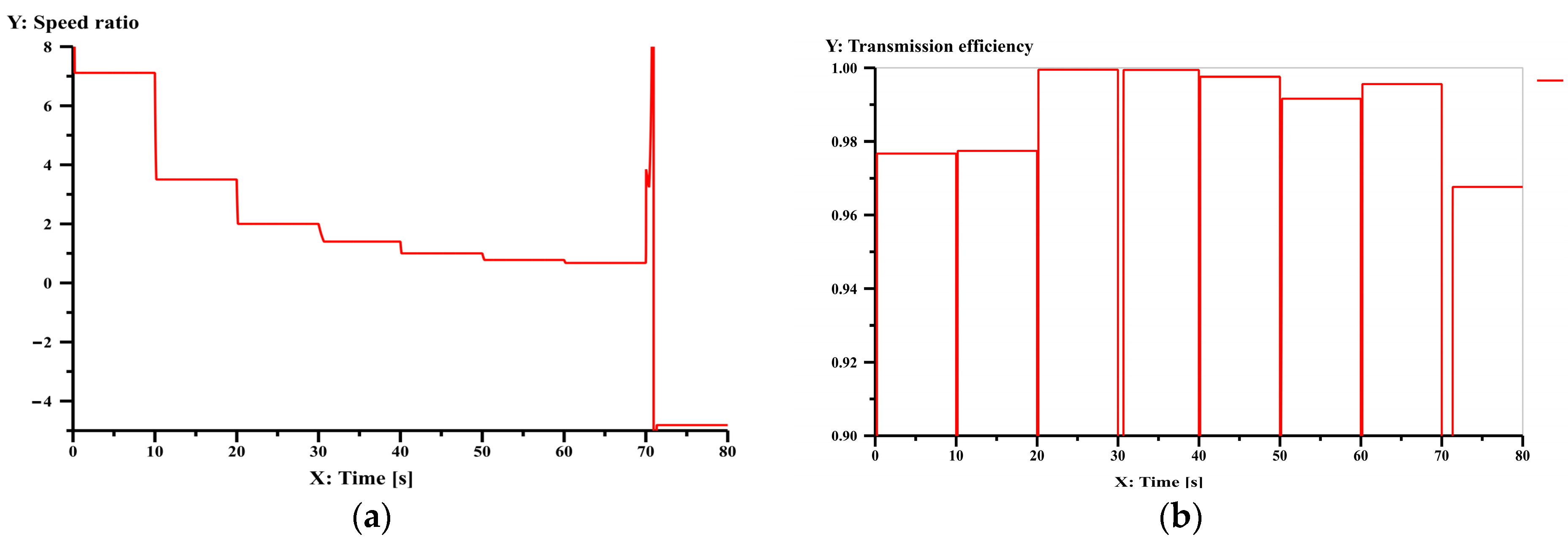
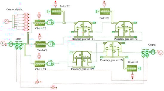
Figure A3.
AMESim simulation model of Figure 12a.
Figure A3.
AMESim simulation model of Figure 12a.
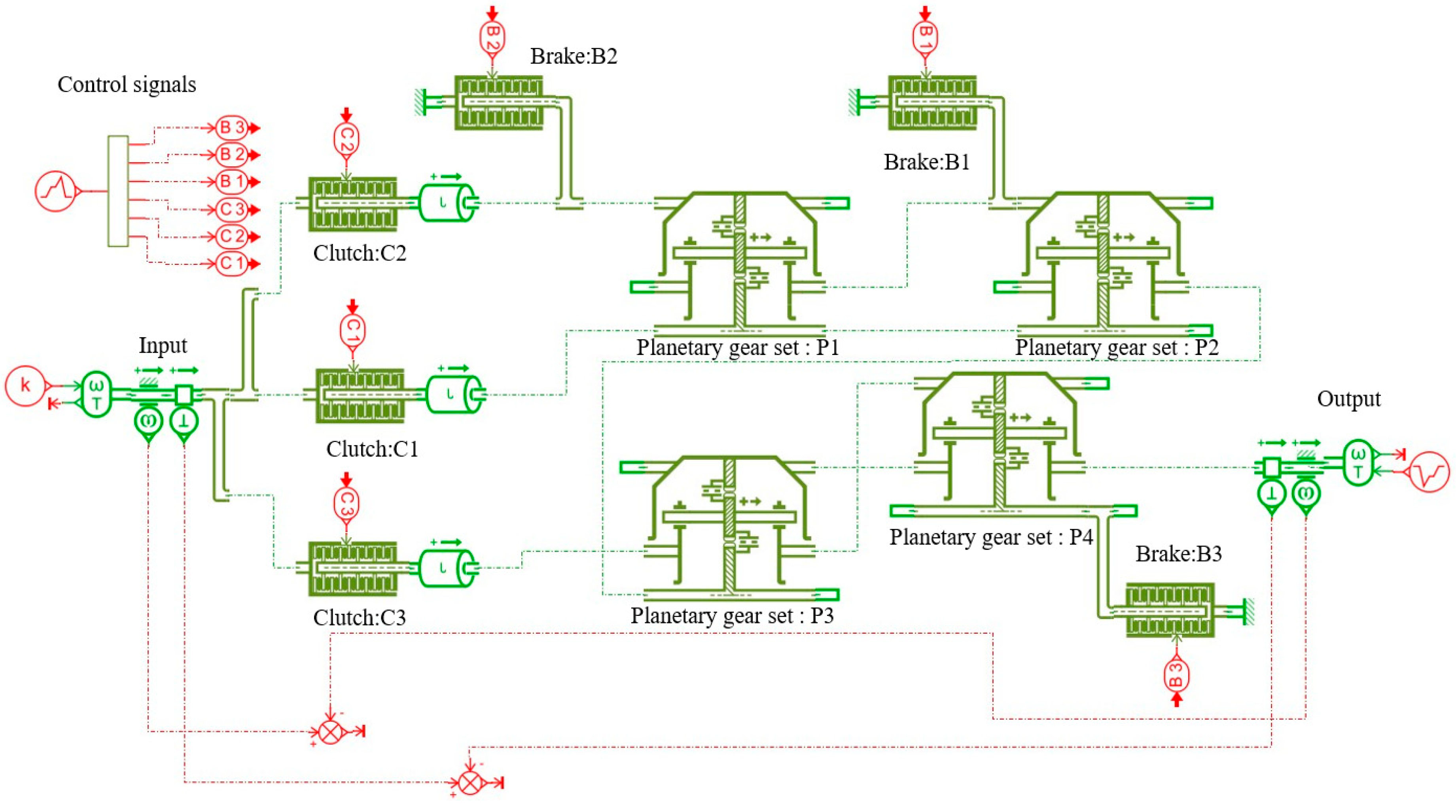
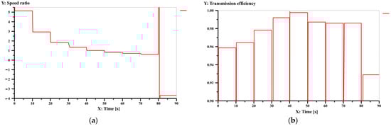
Figure A4.
Simulation result of speed ratio (a) and transmission efficiency (b) for each gear of Figure 12a.
Figure A4.
Simulation result of speed ratio (a) and transmission efficiency (b) for each gear of Figure 12a.
References
- Cooney, T.J. The New Allison HD4070 Transmission-Design, Development and Applications; SAE International: Warrendale, PA, USA, 1999. [Google Scholar]
- Xue, H.L.; Liu, G.; Yang, X.H. A review of graph theory application research in gears. Proc. Inst. Mech. Eng. Part C J. Mech. Eng. Sci. 2015, 230, 1697–1714. [Google Scholar] [CrossRef]
- Hsu, C.H.; Huang, R.H. Systematic design of six-speed automatic transmissions with an eight-link two-DOF Ravigneaux gear mechanism. ASME J. Mech. Des. 2009, 131, 011004. [Google Scholar] [CrossRef]
- Hwang, W.M.; Huang, Y.L. Connecting clutch elements to planetary gear trains for automotive automatic transmissions via coded sketches. Mech. Mach. Theory 2011, 46, 44–52. [Google Scholar] [CrossRef]
- Esmail, E.L. Nomographs for synthesis of epicyclic-type automatic transmissions. Meccanica 2013, 48, 2037–2049. [Google Scholar] [CrossRef]
- Xie, T.; Hu, J.; Peng, Z.; Liu, C. Synthesis of seven-speed planetary gear trains for heavy-duty commercial vehicle. Mech. Mach. Theory 2015, 90, 230–239. [Google Scholar] [CrossRef]
- Peng, Z.X.; Hu, J.B.; Xie, T.L.; Liu, C.W. Design of multiple operating degrees-of-freedom planetary gear trains with variable structure. ASME J. Mech. Des. 2015, 137, 093301. [Google Scholar] [CrossRef]
- Yang, F.; Feng, J.; Du, F. Design and power flow analysis for multi-speed automatic transmission with hybrid gear trains. Int. J. Automot. Technol. 2016, 17, 629–637. [Google Scholar] [CrossRef]
- Dong, P.; Liu, Y.; Tenberge, P.; Xu, X. Design and analysis of a novel multi-speed automatic transmission with four degrees-of-freedom. Mech. Mach. Theory 2017, 108, 83–96. [Google Scholar] [CrossRef]
- Liu, J.; Yu, L.; Zeng, Q.; Li, Q. Synthesis of multi-row and multi-speed planetary gear mechanism for automatic transmission. Mech. Mach. Theory 2018, 128, 616–627. [Google Scholar] [CrossRef]
- Hoang, N.T.; Yan, H.S. On the design of in-wheel-hub motor transmission systems with six-link mechanisms for electric vehicles. Energies 2018, 11, 2920. [Google Scholar] [CrossRef]
- Du, M.; Yang, L. A basis for the computer-aided design of the topological structure of planetary gear trains. Mech. Mach. Theory 2020, 145, 103690. [Google Scholar] [CrossRef]
- Ho, T.T.; Hwang, S.J. Configuration synthesis of novel hybrid transmission systems using a combination of a Ravigneaux gear train and a simple planetary gear train. Energies 2020, 13, 2333. [Google Scholar] [CrossRef]
- Buchsbaum, F.; Freudenstein, F. Synthesis of kinematic structure of geared kinematic chains and other mechanisms. ASME J. Mech. 1970, 5, 357–392. [Google Scholar] [CrossRef]
- Tsai, L.W. An application of the linkage characteristic polynomial to the topological synthesis of epicyclic gear trains. J. Mech. Transm. Autom. Des. 1987, 109, 329–336. [Google Scholar] [CrossRef]
- Tsai, L.W.; Lin, C.C. The creation of nonfractionated, two-degree-of-freedom epicyclic gear trains. J. Mech. Transm. Autom. Des. 1989, 111, 524–529. [Google Scholar] [CrossRef]
- Hsu, C.H.; Hsu, J.J. An efficient methodology for the structural synthesis of geared kinematic chains. Mech. Mach. Theory 1997, 32, 957–973. [Google Scholar] [CrossRef]
- Del Castillo, J.M. Enumeration of 1-DOF planetary gear train graphs based on functional constraints. ASME J. Mech. Des. 2002, 124, 723–732. [Google Scholar] [CrossRef]
- Rao, Y.V.D.; Rao, A.C. Generation of epicyclic gear trains of one degree of freedom. ASME J. Mech. Des. 2008, 130, 232–245. [Google Scholar] [CrossRef]
- Yang, W.; Ding, H. The complete set of 1-dof planetary gear trains with up to 9 Links. ASME J. Mech. Des. 2018, 141, 043301. [Google Scholar] [CrossRef]
- Yang, W.; Ding, H.; Kecskeméthy, A. Automatic structural synthesis of non-fractionated 2-DOF planetary gear trains. Mech. Mach. Theory 2021, 155, 104125. [Google Scholar] [CrossRef]
- Shanmukhasundaram, V.R.; Rao, Y.V.D.; Regalla, S.P. Enumeration of displacement graphs of epicyclic gear train from a given rotation graph using concept of building of kinematic units. Mech. Mach. Theory 2019, 134, 393–424. [Google Scholar] [CrossRef]
- Cui, R.; Ye, Z.; Sun, L.; Zheng, G.; Wu, C. Synthesis method for planetary gear trains without using rotation graphs. Proc. Inst. Mech. Eng. Part C J. Mech. Eng. Sci. 2021, 236, 972–983. [Google Scholar] [CrossRef]


Disclaimer/Publisher’s Note: The statements, opinions and data contained in all publications are solely those of the individual author(s) and contributor(s) and not of MDPI and/or the editor(s). MDPI and/or the editor(s) disclaim responsibility for any injury to people or property resulting from any ideas, methods, instructions or products referred to in the content. |
© 2023 by the authors. Licensee MDPI, Basel, Switzerland. This article is an open access article distributed under the terms and conditions of the Creative Commons Attribution (CC BY) license (https://creativecommons.org/licenses/by/4.0/).