Abstract
This paper presents a passive concentrator for single-phase inverters with a three-phase output, which uses magnetically coupled reactors. Due to the development of renewable energy systems, the proposed systems may enable the easier integration of converters in the form of inverters with the power system. Two variants of cooperation of the concentrator with single-phase voltage inverters were considered. The first variant proposed a system topology in which three single-phase full-bridge inverters were connected to the concentrator, while the other variant proposed six half-bridge inverters. A control system of the inverters that does not use PWM was developed. A common star point was created for the supply voltages in the form of a capacitive divider covering all the inverters. An analysis of the concentrator system was presented, taking into account the cooperation with inverters. The overall power of the TDSλ system was defined and the relationship for its determination was given. Simulation studies were described, presenting the obtained voltage and current waveforms. The impact of changing the supply voltage of the inverters on the operation of the concentrator and the shape of the output voltages was assessed. The proposed systems allow you to connect 3 or 6 single-phase inverters. The use of magnetically coupled reactors enables the use of a magnetic system of lower power and size. The described concentrators enable the generation of multi-level three-phase output voltage with a low THD content.
1. Introduction
The changes in renewable energy sources and electromobility are currently the main reasons driving development in power electronics, which are contributing to the emergence of circuit solutions geared toward the cooperation of different converters with each other and the conditioning of electricity. These aspects are particularly important when considering the possibilities of connecting the RES (Renewable Energy Source) network to the existing power system [1]. In renewable energy systems related to photovoltaics, the basic group of converters are voltage inverters. The vast majority of these are single-phase inverters [2,3,4].
In the cases mentioned, one of the most important components of the system is the inverter. The paper [5] provides a comprehensive overview of the different types of inverters currently used in various applications and variants of power systems. Generally, a traditional voltage-fed inverter is used, where two voltage levels can be generated [6]. For other applications, especially those requiring high power conversion (e.g., onshore power supply systems), multi-level inverters (MLIs) are used. An MLI is a converter system in which different types of power electronic devices are interconnected in such a way and are fed from DC systems to provide a waveform with more levels on the output side [7,8]. MLI circuits are desirable for a variety of applications due to intrinsic benefits, for example, low switching voltages, low DV/DT ratio on switches, reliability, lower cost, reduced complexity, improved THD, and exceptional performance when used in applications [9,10].
Since the use of multilevel inverters has begun, numerous layout changes have been made to the inverters. Their control strategies have also changed. This has resulted in increased circuit complexity, weight, and cost; stress on switches; electromagnetic compatibility (EMC)/electromagnetic interference (EMI) problems; and circuit losses. These effects lead to performance degradation and affect the nature of power in network/distribution systems. For this reason, traditional bilevel inverters are still very popular in low power systems [5].
Various modulation schemes are available and are used to build control strategies for inverter operations [11,12]. A significant proportion of the modulators used for inverters are based on pulse width modulation (PWM) modifications. Modulations using PWM mainly increase the switching losses of the electronic keys used in inverters [12,13,14,15].
As mentioned earlier, the use of multi-level inverters and appropriate control strategies allows for multiple levels of output voltages. Multi-level voltage is usually associated with lower THD and better power quality [16]. As it has been shown, obtaining such a voltage requires the use of complex inverter structures and complicated control strategies based on a large number of electronic key switches [17].
This paper describes a system that uses magnetically coupled reactors connected like a TDS circuit and single-phase inverters with a simple control strategy to provide multiple interfaces to low-power systems (such as photovoltaic panels) [18]. The proposed system, which has been dubbed a concentrator, also has the property of producing a three-phase and multi-level voltage system with the right control strategy.
The development of a concentrator with multiple inputs and outputs in the form of a three-phase system requires the analysis of systems that allow for the integration of multiple inverters in one system. For this purpose, systems based on transformers, multi-winding transformers, and systems using magnetically coupled reactors were compared [19,20,21,22,23,24]. The works [19,24] describe special multi-winding transformers that enable the conversion from three phases to five phases. Transformers of this type were mainly built to power multi-phase drives, e.g., five-phase. In these works, they were not combined with inverters. The works [19,20,21,22] indicate various structures of multi-winding transformers and their advantages/disadvantages. The largest advantage of this type of transformer is galvanic separation and conversion from a certain number of phases to another number of phases. The disadvantage of this type of transformer is the high cost in relation to the power. Another disadvantage of this type of transformer is its size. However, in [23], it is pointed out that it is still smaller than in the case of traditional transformers, especially if a multi-winding transformer is compared to an appropriate number of single-phase transformers. Magnetically coupled reactors have favorable properties when it comes to the relationship between size, weight, and power. Due to their simplified construction, their dimensions are much smaller than typical transformers or multi-winding transformers. However, ensuring the possibility of conversion from several phases to several other phases is possible by appropriately connecting reactors. The works [24,25] thoroughly analyzed the properties of reactors that can be used in power electronic systems or for connecting them with other systems.
According to the authors, it is important to connect inverters to each other and to the public power system so that this process is effective and ensures the conditioning of electricity, the result of which is maintaining high quality. In the context of the concentrator variants described in the article, efficiency would mean the number of electricity sources, e.g., photovoltaic strings, that can be connected to one concentrator. The more inverters that are connected, the better the concentrator that is used. Using magnetically coupled reactors and inverter control allows for obtaining multi-level-output voltage waveforms characterized by a low content of higher harmonics [18].
The described concentrator is a passive system. Its main advantage is that it does not need to be powered and is not controlled. The mentioned advantages make the concentrator much easier to use and more resistant to damage. The topology used to connect magnetically coupled reactors reduces their number in the proposed concentrator variants. Reducing the number of magnetic elements in power electronic devices is currently a desirable measure due to material costs and the tendency to minimize the dimensions of devices. The connection of the magnetically coupled reactors (MCRs) used is called TDSλ (three-phase coupled reactors in the lambda connection variant) and is described in more detail in [26]. A significant advantage of the TDSλ system is that its weight and size are significantly smaller for the same power compared to a transformer that would be designed for that power. On the other hand, a significant disadvantage of the TDSλ system is the lack of galvanic separation that transformers or multi-winding transformers have.
However, the most important advantage of the described solution is that by selecting the appropriate number of turns for the adopted topology of connecting reactors at the output of the structure, one obtains—with a simple control of single-phase inverters—three-phase multi-level waveforms, which translate into a very low THD content (Total Harmonic Distortion) for output voltages and currents [26].
2. A System of Magnetically Coupled Reactors as a Passive Coupling for Single-Phase Inverters
The three-phase coupled reactor (Harmonic Canceling Reactor, Harmonic Blocking Current Transformer) was patented in 1974 by Meier [26]. In 1989–1990, Depenbrock and Niermann published a 12-pulse rectifier system using three-phase reactors coupled for parallel operation of two three-phase bridge systems [27,28]. The system using magnetically coupled reactors of the TDSλ type was also used to build 12-, 18-, or 36-plus rectifiers as stable voltage sources for multi-level inverters in the papers [29,30,31]. The TDSλ structure is optimal in terms of the number of magnetic elements used. It is characterized by high efficiency (above 90%) and its main parameter dependent on the load is the overall power [26].
The three-phase coupled reactors, thanks to its appropriate design, blocks certain higher harmonics (of the orders of 5, 7, 11, 13, 17, 19, etc.) and also transforms two three-phase systems with a given mutual phase shift into one three-phase system.
The reactors (MCR) are composed of three separate magnetic cores with an appropriately selected number of turns (Nx, Ny, Nz). Thanks to the appropriately selected number of reactors windings, their output results in two three-phase and symmetrical voltage systems shifted in phase by an angle of π/6, but the mutual phase shift can be modified by changing the number of windings in a wide range. This possibility was used in the construction of multi-pole rectifiers, i.e., 18-, 24-, or 36-plus rectifiers [26]. These converters use several TDSλ structures simultaneously.
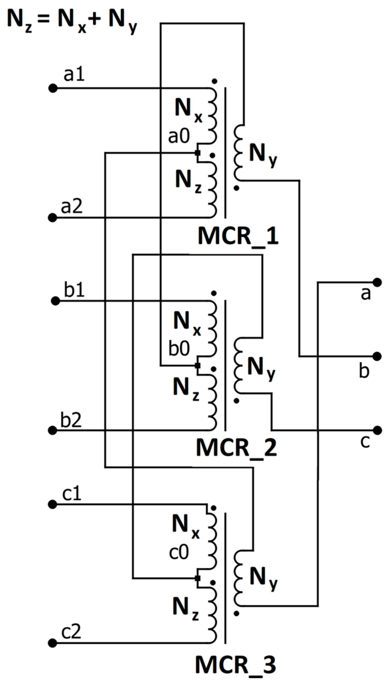
Using Equation (1), it is possible to select, for a given angle—in our case, the angle π/12—the number of turns Nx and Ny, because the number of turns denoted by Nz results from relationship (2). The value of the phase angle between the spatial vectors of the output voltages of the TDSλ system (Figure 1) directly depends on the ratio of the number of turns (Ny/Nz) of the appropriate windings. According to [9], the dependence of the reactor ratio p in the TDSλ system on the displacement angle α of three-phase supply voltage systems is obtained. The ratio of the number of turns that meets the above condition for the appropriate reactors of the TDSλ system is
where p is the gear ratio resulting from the ratio of the number of turns Nx to Ny of the appropriate reactors seen from the inverter side and from the load side, and α is the shift angle between the voltages at the reactor input of a given phase—in the case of a concentrator, it is an angle of π/12.
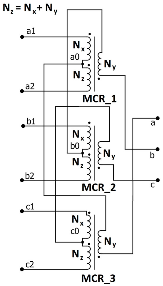
Figure 1.
Winding configuration for the coupled reactor system in the TDSλ system, where MCR1,2,3 are magnetically coupled reactors numbered 1, 2, 3, respectively; Nx, Ny, Nz—numbers of turns for reactors in the TDSλ system; a1, a2, b1, b2, c1, c2 are inputs of TDSλ; a0, b0, c0 are connections between reactors; a, b, c are outputs of TDSλ.
Magnetically coupled reactors play a similar role to converter transformers in this system. However, compared with converter transformers, they are characterized by a power several times lower but a more complex system of windings. The diagram of magnetically coupled reactors in the TDSλ system is shown in Figure 1.
The topology of the TDSλ system presented in Figure 1 enables various configurations of connecting single-phase inverters and then obtaining a three-phase voltage with a low THD content at the output. The presented reactor system introduces a constant shift, which creates three-phase voltage with a large number of levels at the reactor output.
Single-phase inverters connected to a TDSλ system require a dedicated control system. The classic control strategy for single-phase voltage inverters requires that the electronic keys in the inverters be switched every π, while in the proposed system, its control strategy should also take into account shifts of the angle π/12, which are introduced by the TDSλ system. To ensure a shift of the angle π/12 in the TDSλ system, an appropriate winding gear of the inductive elements must be selected [12]. In the case under consideration, these windings were selected in the following ratio: 3.72:1:2.72. For the purposes of the developed concentrator, first, the gears that will ensure the aforementioned shift in vectors were calculated. Then, for the assumed power, the number of windings was selected to not lead the core to saturation. For this number of windings, the self and mutual inductances were calculated. Further simulation studies and tests were performed for the following number of windings: 279:75:204, which corresponds to the design of the TDSλ system for 2 kW of power.
Taking into account the presented requirements regarding the input voltages for the TDSλ system—coming from single-phase inverters connected to reactors—two variants of connecting the inverters to the concentrator are considered in this paper.
An important feature of the described solution is the fact that the inverter control uses a basic on–off strategy for switching electronic keys. This strategy does not use PWM (Pulse-width Modulation). Thanks to this, losses resulting from switching electronic keys are minimized and the control system is very simple [32,33,34].
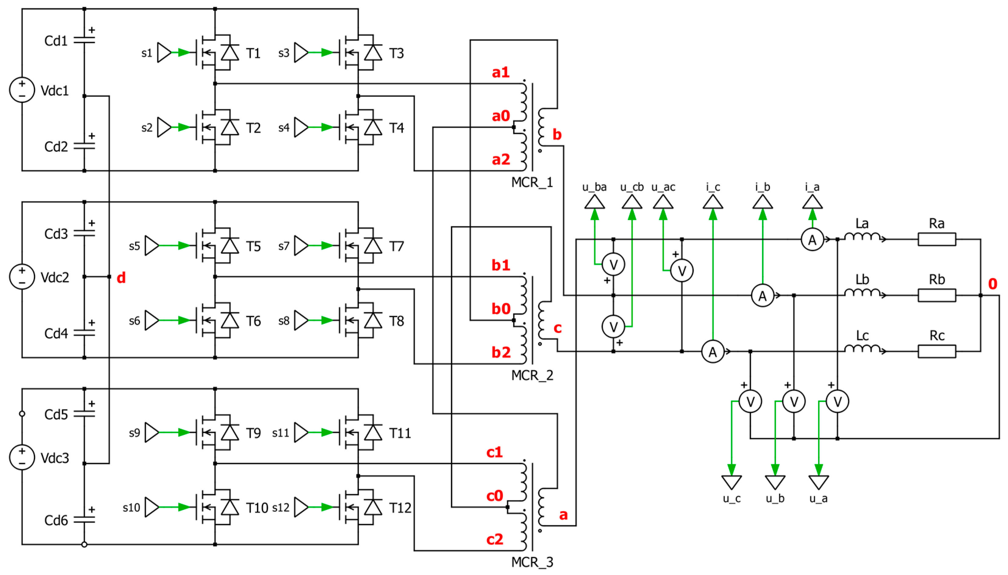
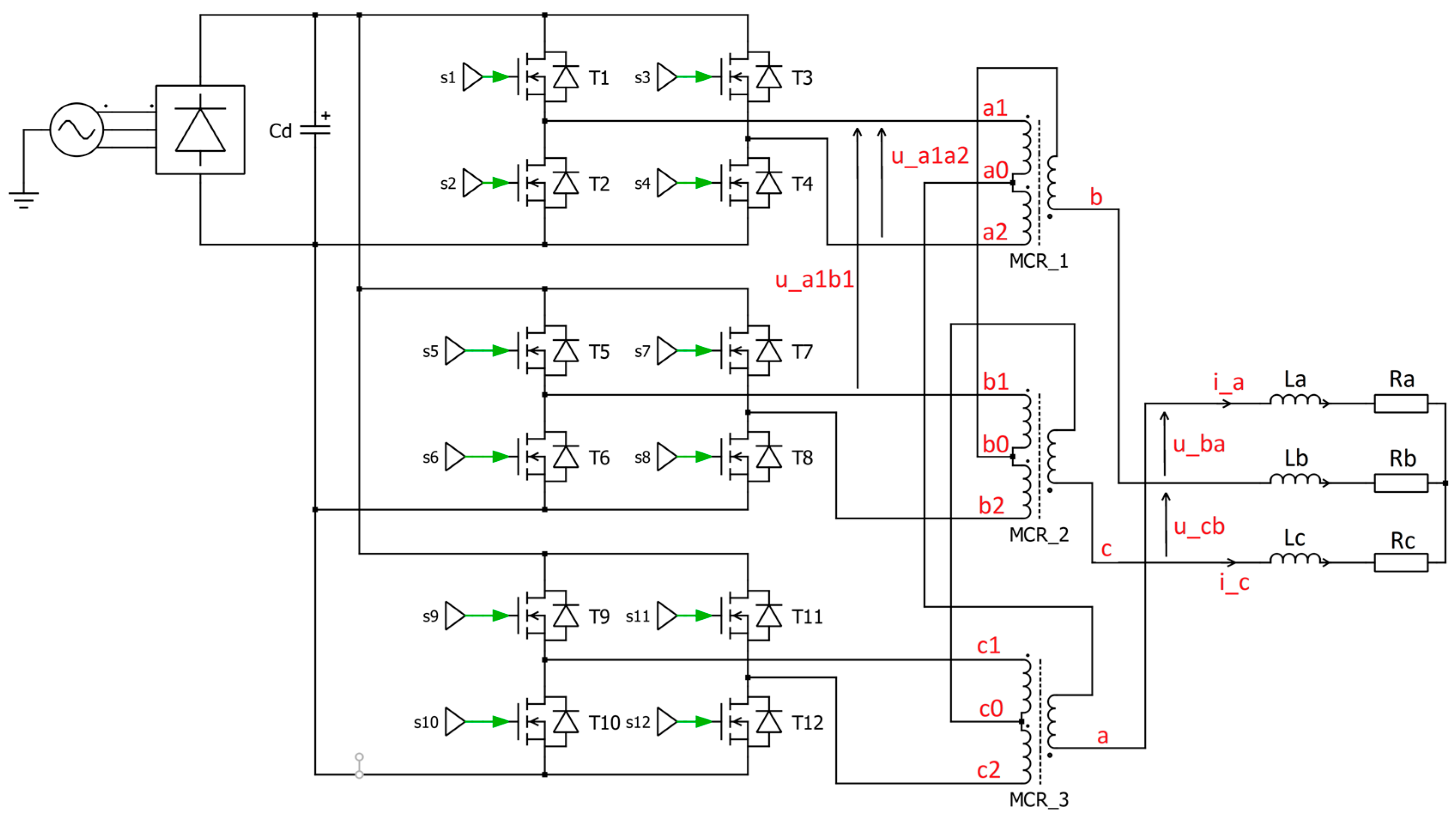
In the first variant, three single-phase inverters in an H-bridge system were connected to the TDSλ system (Figure 1). Figure 2 shows the topology of the concentrator with three of this type of inverter.
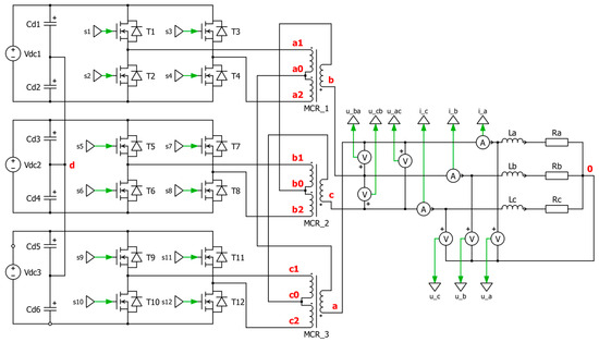
Figure 2.
Topology of a passive concentrator in a system with three single-phase inverters.
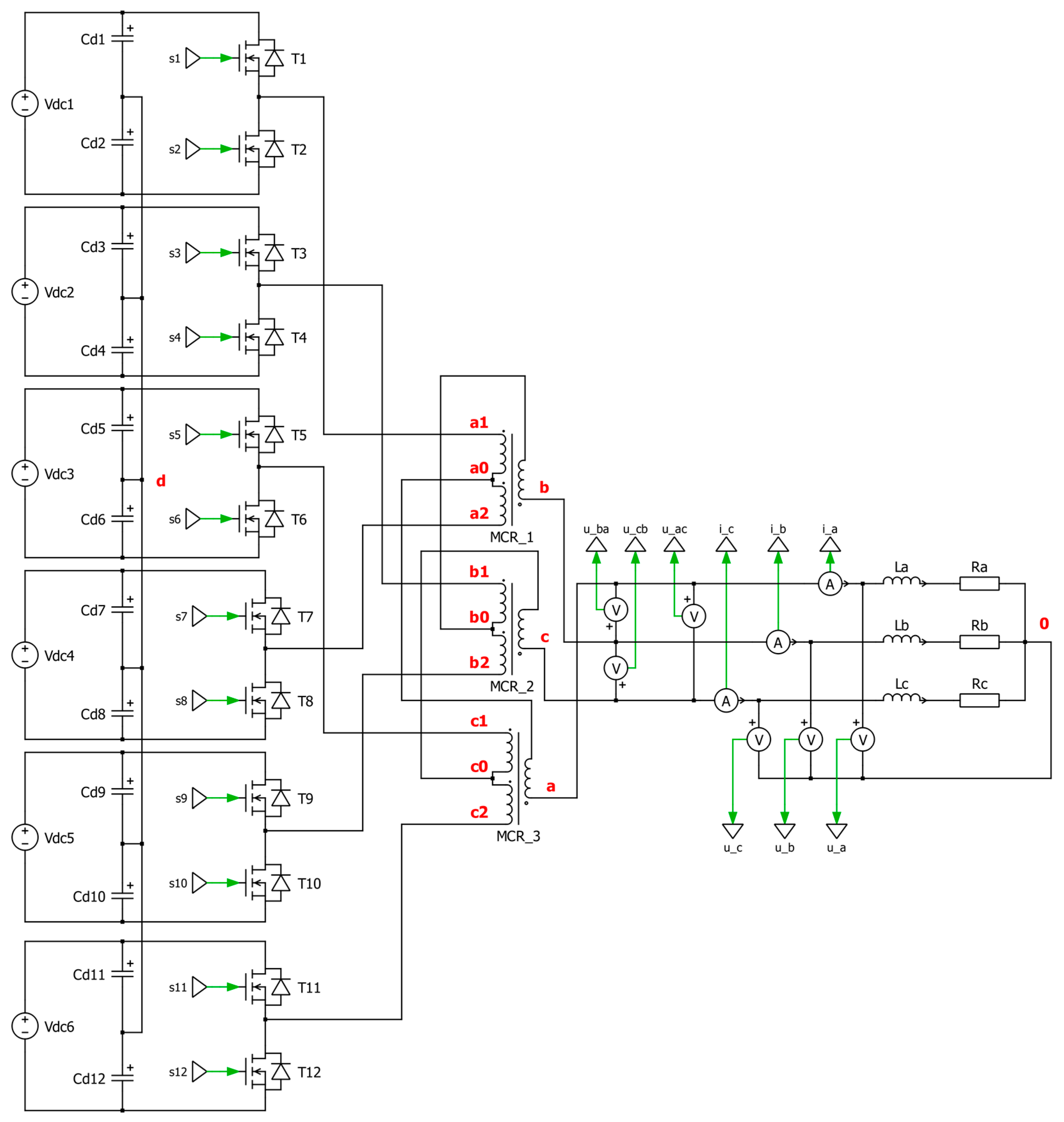
Figure 3 shows the other variant of the concentrator. In this version, six single-phase half-bridge inverters are connected to the TDSλ system, where there are two inverters for each reactor MCRi, where i is the reactor number with indexes from 1 to 3.
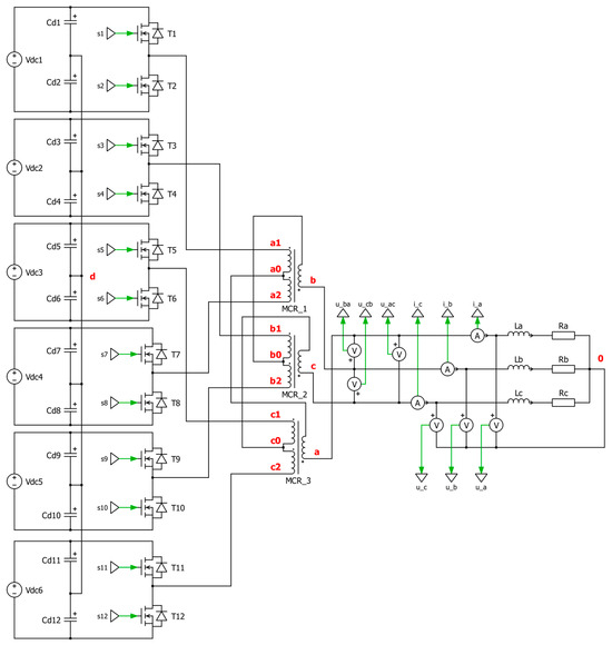
Figure 3.
Topology of a passive concentrator in a system with six single-phase inverters.
The characteristic points of the concentrator system are marked in the diagrams presented in Figure 2 and Figure 3. These points were used in the concentrator analysis to determine voltages important for the operation of the system: d—the star point of the capacitive voltage divider; a1, a2, b1, b2, c1, and c2—the inputs of the TDSλ system; a, b, and c—the outputs of the TDSλ circuit, which also correspond to the phases; and 0—the reference point for the load circuit. Characteristic points in the diagrams (Figure 2 and Figure 3) are additionally highlighted in red. A description of the analysis is included later in the article.
The topology of the single-phase inverter used is the main difference between the concentrator variants.
An important element in every diagram is the capacitive voltage divider (created by capacitors marked Cd1 = Cd2 = … = Cd12), which creates a common star point for all voltages in the intermediate circuits of single-phase inverters. The purpose of the capacitive divider is to create a connection for the alternating-current components in the power supply circuit while eliminating the direct components.
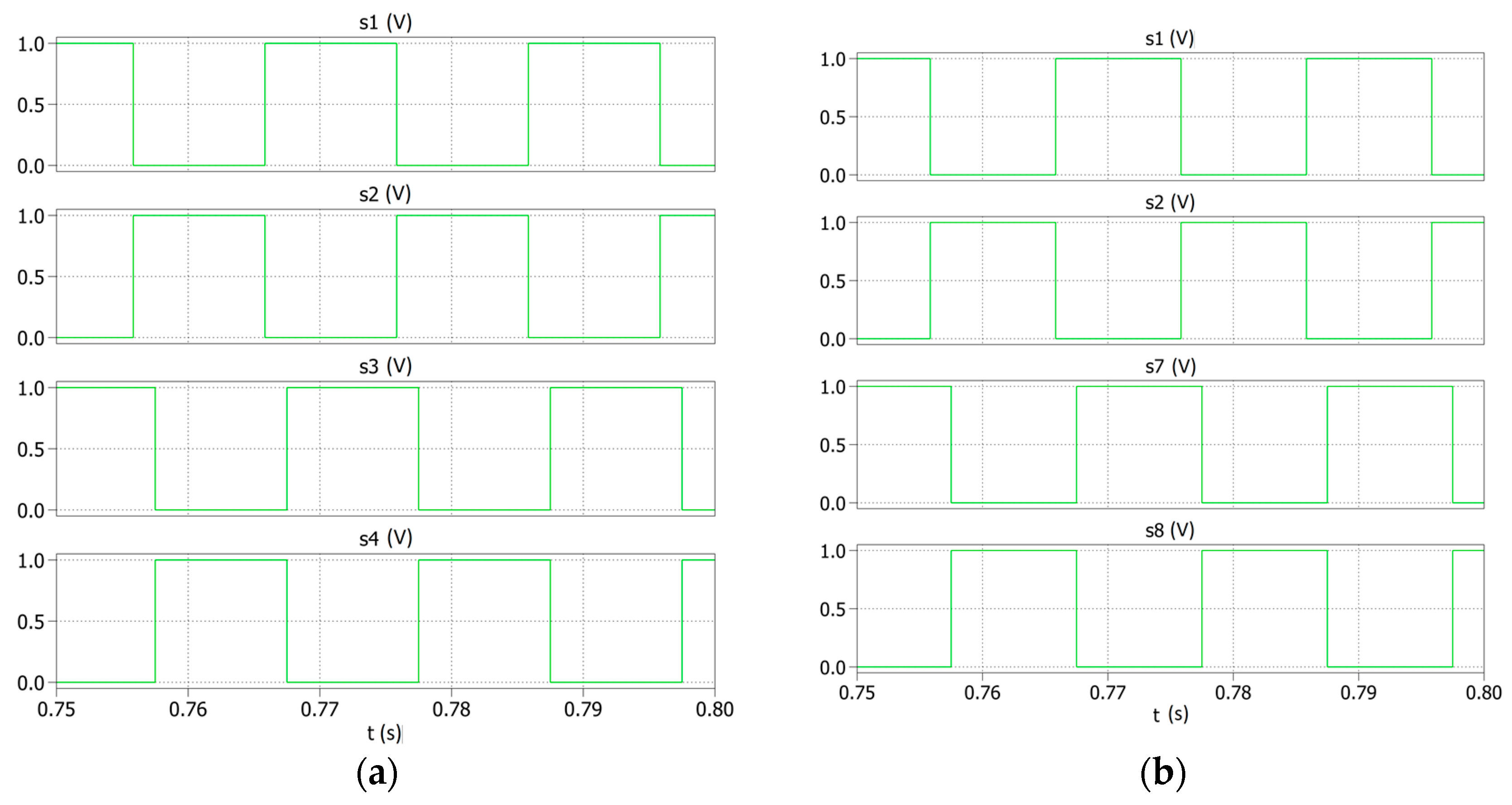
Figure 4a,b show example signals controlling electronic keys for inverters responsible for generating voltage on the reactor marked MCR1 in both the considered versions of the concentrator. The remaining inverters in these concentrator variants are controlled based on a similar principle, but the control signals (marked s1…12) are phase-shifted by 2π/3 and 4π/3 to ensure compatibility with the three-phase power system. In both the cases, the inverters shape the phase B voltage.
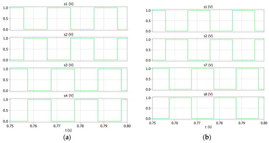
Figure 4.
Examples of signals controlling the inverters connected to the MCR1 reactors in (a) the first variant with full-bridge inverters and (b) the second variant with half-bridge inverters.
Simplifications are made for the purposes of the analysis. In the concentrator system with single-phase inverters, it is assumed that the supply voltages of the inverters are the same and meet the condition: Vdc1 = Vdc2 = … = Vdc6 = Vdc. In order to keep the analysis readable and transparent, we focus on the cooperation of the inverters with the first MCR1 reactor and the influence of the system on the “a” phase. In selected stages of the analysis, there also have to be references to other characteristic points of the concentrator. By making the aforementioned assumptions, the analysis allows for taking into account the operation of the systems presented in Figure 2 and Figure 3.
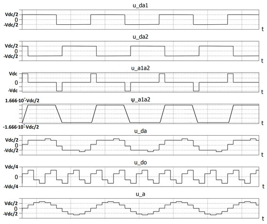
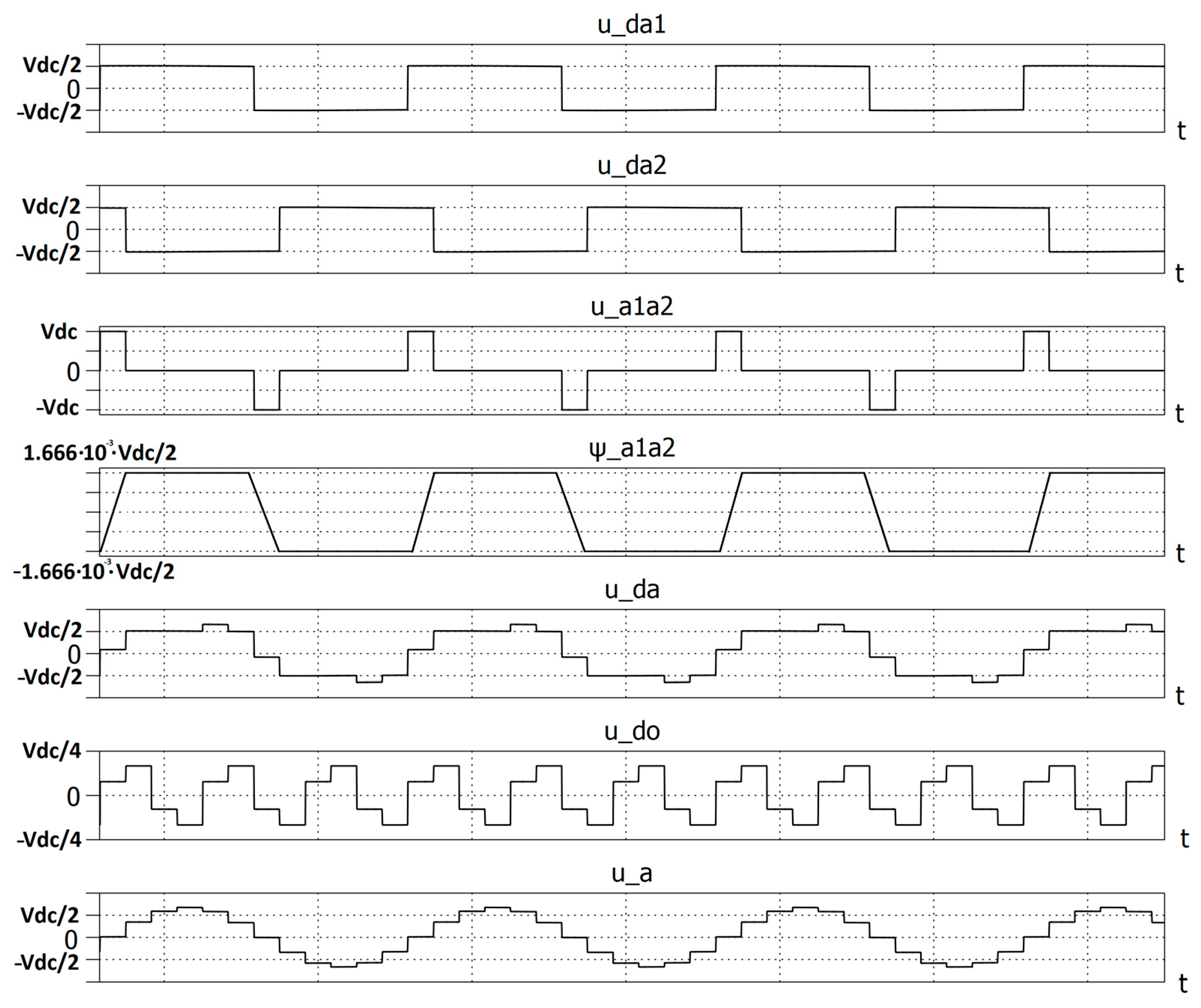
The voltage waveforms important for the operation of the system and the magnetic flux are illustrated in Figure 5.
The maximum value of the magnetic flux coupled to the windings connected between terminals a1 and a2 is determined using the following formula:
The voltages between points a, b, c, and d result from the following equations:
The voltage waveforms u_ad in phase a are illustrated in Figure 5. To determine the voltage waveforms, occurring between points a and 0, the zero-component voltage u_d0, between points 0 and d, must be determined.
The voltage measured between points a, b, c, and 0 is equal to:
The voltage waveforms u_d0 and u_a are shown in Figure 5. The voltages u_a,b,c thus have a twelve-phase waveform in period T. The fundamental harmonic of this voltage, u_am, has a value of 1.318 Vdc and the higher harmonics have amplitudes equal to u_aI/(12 k ± 1), k = 1, 2, 3.
In idle operation of the system, the amplitude of the fundamental harmonic of the twelve-step voltage is equal to the amplitude of the supply voltage.
When designing a TDSλ choke, it is necessary to start from its dimensional power, which can be determined by assuming that the magnetic flux of the choke is generated by a sinusoidal voltage of the mains voltage frequency f. The dimensional power is defined as the arithmetic average of the winding powers of the equivalent transformer (with two windings).
We are therefore entitled to write the following equation:
The effective value of this voltage is therefore equal to
where T is the period of the output voltage from the TDSλ system.
If m is the number of choke phases and IRMS is the RMS value of the current in the windings, SG can be expressed as follows:
The factor of 0.5 appearing in brackets on the right side of the equation results from the fact that the choke has no secondary windings.
The final result is obtained:
The higher harmonic currents generated by the input voltage of the chokes are attenuated by the inductances of the chokes included in the power source circuit and can therefore be neglected, which means that the effective values of the currents in the windings of the chokes are approximately equal to the effective values of the fundamental harmonics. The amplitude of the fundamental harmonic of a twelve-step voltage is expressed by the following formula:
where q = 12 is the pulsation of this voltage for the period T. Thus, from Equation (13), one obtains
Since the currents produced by the individual converters are shifted in phase with respect to the base harmonic of the twelve-step voltage by an angle of ±π/12, the following power equation is obtained:
where I1,1, I1,2, …, and I1,6 denote the effective harmonic values of the fundamental currents in the choke windings, derived from single-phase inverters.
The following two chapters present the results of simulation and experimental studies.
3. Simulation Studies
The simulation tests presented the basic waveforms of output voltages and currents with a resistive–inductive load with the following values: R1 = R2 = R3 = 10 Ω and L1 = L2 = L3 = 20 mH. Simulation tests were performed in the PLECS program. To show the basic capabilities of the system, simulations were performed in which the operation of the concentrator was presented when the inverters were powered with the DC voltage of Vdci = 400 V, where I denotes the consecutive number of the inverter and takes values from 1 to 6. This work also shows a scenario in which the first inverter connecting the voltage to the MCR1 reactors is reduced to Vdc1 = 200 V. This study aimed to illustrate how the concentrator reacts to a change in the supply voltage, which often occurs in photovoltaic subnets as a result of, for example, the darkening of the panel chain or damage to one of them.
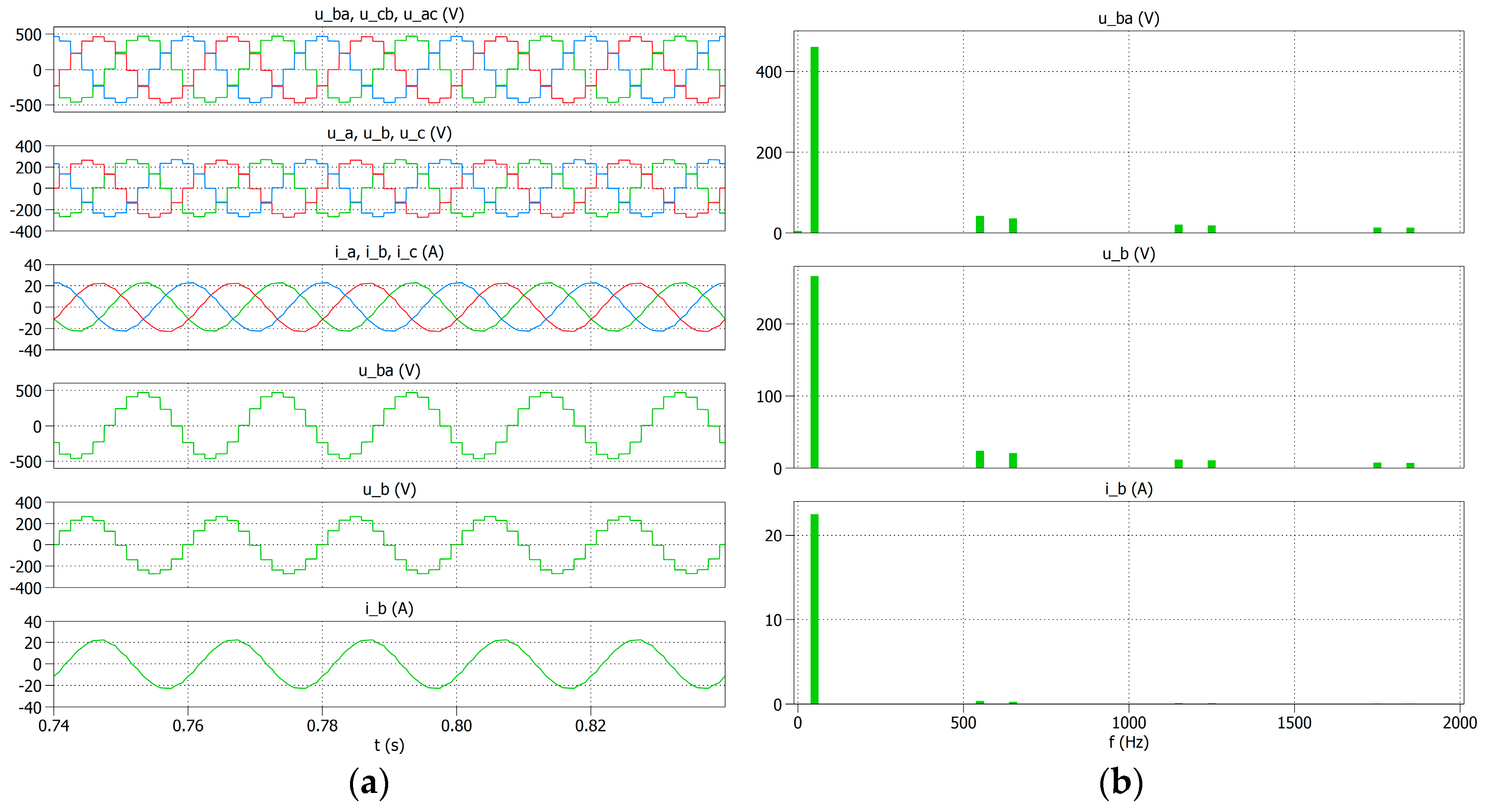
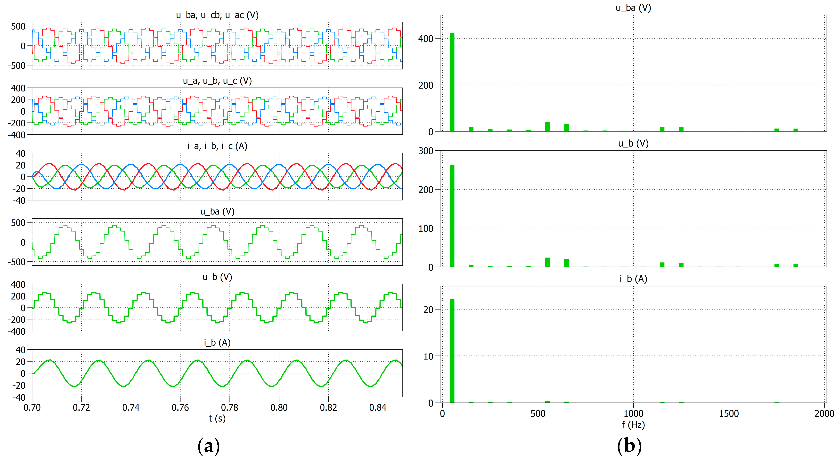
Figure 6a shows the voltage and current waveforms for phase B and RL loads in the first and second variants. Figure 6b shows the amplitude spectra of these waveforms. Although different inverters are used in both the variants of the concentrator, the voltage and current waveforms at the reactor output and their spectra are the same. Therefore, the simulation results are not separately presented for the two variants of the concentrator in its typical operation. This distinction was made in the second stage of the simulation research, in which the sensitivity of the concentrator variants to changes in the supply voltage was assessed.
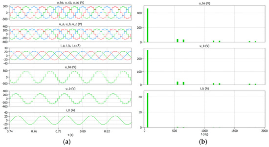
Figure 6.
Voltage and current waveforms at the output of the TDSλ system for the first variant of the concentrator in phase B (a) and the amplitude spectrum of this voltage and current (b).
The operation of the TDSλ system with three or six single-phase inverters and the Vdci inverter supply voltages of the same value allows for obtaining the same values and shapes of the output voltages and currents. The phase voltage is multi-level and the current is close to a sinusoidal waveform. The THD content for phase B voltage THD_ub is 15.1%, and for the current of this phase, the THD_ib is 2%. The amplitude spectra for phase B confirm the THD values presented above. There is a small content of 11th (9%) and 13th (7.5%) harmonics in the output voltage spectrum. For comparison, the same harmonics for the output current constitute 1.5% for the 11th harmonic and 1.1% for the 13th harmonic.
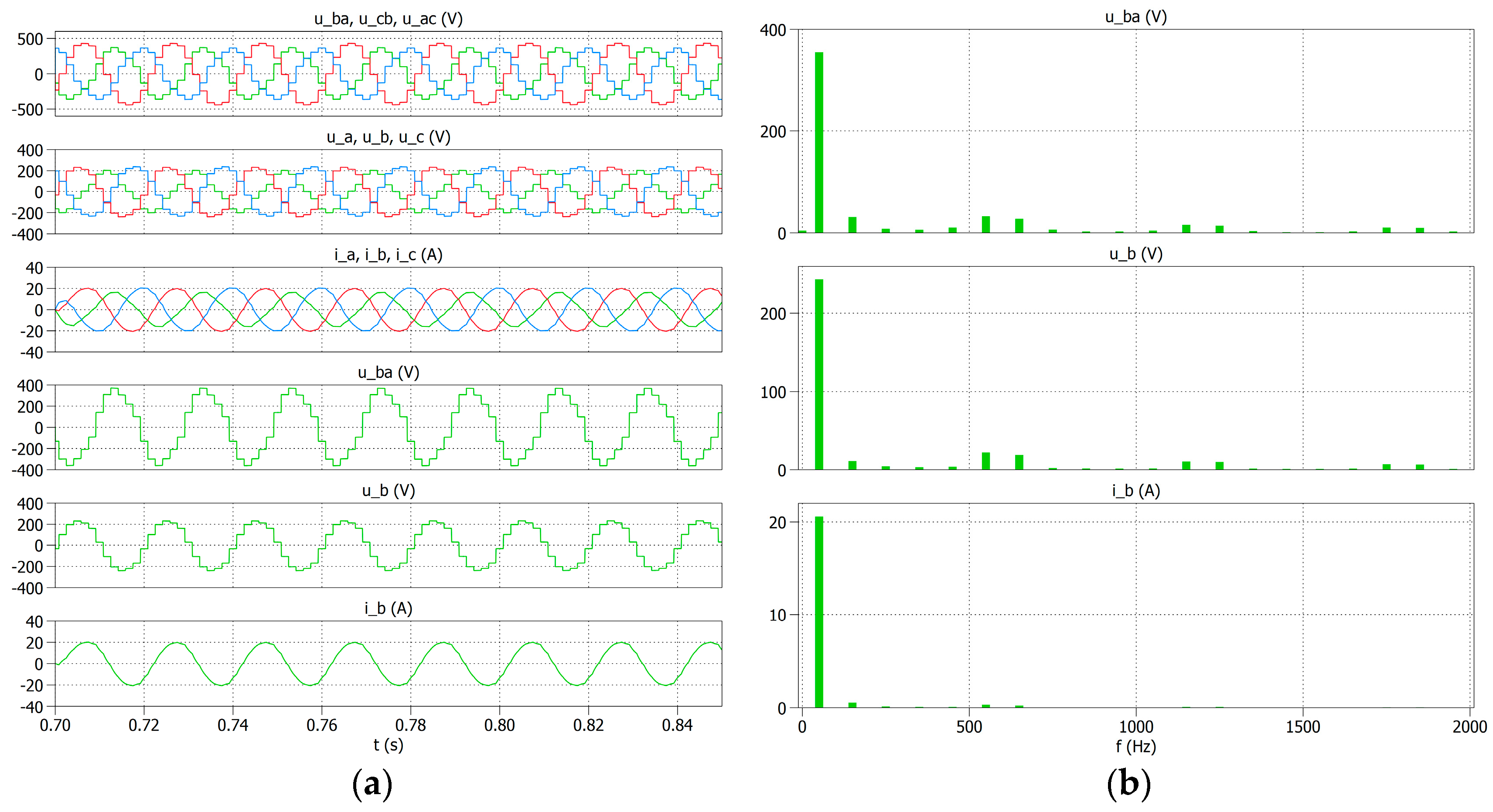
On the other hand, Figure 7 and Figure 8 show the waveforms of the output voltages and currents for both the variants of the concentrator in a situation where, for the first inverter (the first variant inverter with transistors T1, T2, T3, and T4, and the other variant inverter with transistors T1 and T2), the supply voltage was reduced to half, i.e., Vdc1 = 200 V. Reducing the supply voltage for one inverter in each of the considered concentrator variants caused a disturbance in the form of a change in the shape of the output voltage waveforms and a reduction in the amplitude of the currents. The resulting waveforms differ in the intensity of changes in the two variants.
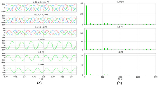
Figure 7.
Voltage and current waveforms in phase B at the output of the TDSλ system in the first variant of the concentrator for the reduced voltage Vdc1 = 200 V (a) and the amplitude spectrum (b).
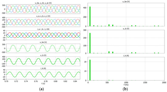
Figure 8.
Voltage and current waveforms in phase B at the output of the TDSλ system in the second variant of the concentrator for the reduced voltage Vdc1 = 200 V (a) and the amplitude spectrum (b).
In the first variant, the concentrator performed much worse after reducing the voltage to 200 V on the first inverter. This reaction of the concentrator results from the fact that in this case, a change in the supply voltage simultaneously influenced the output voltage of the entire second phase. However, a similar change in voltage for the first inverter in the second variant is not so significant for the concentrator and the shape and value of the output voltages. The effect of the voltage change is also noticeable in the amplitude spectral characteristics. In the first variant, in the voltage spectrum (Figure 7b) for phase B, the 3rd harmonic and other odd harmonics are visible, while in the current spectrum, the influence of the 3rd, 11th, and 13th harmonics is visible. In the case of the other variant, a change in voltage in the current spectral characteristics (Figure 8b) is practically imperceptible, while in the case of voltage, only the influence of the 3rd, 11th, and 13th harmonics is visible.
4. Experimental Studies
In the next stage, the adopted concept of the concentrator was verified in the first variant with three voltage inverters for the RL load. For this study, a three-phase power supply with a voltage of 3 × 400 V and a frequency of 50 Hz was used, which, in the DC circuit, allowed for obtaining a voltage of 560 V. The load consisted of three resistors with a value of 3 × 50 Ω and a three-phase reactor with a value of 3 × 50 mH.
The experimental system was built according to the diagram shown in Figure 9. When comparing the original topology of the concentrator in this version, shown in Figure 2, with the one used in the experimental study, a simplification was used, which involves changing the power source of the entire structure. The simplification results from the limited capabilities of the current laboratory station.
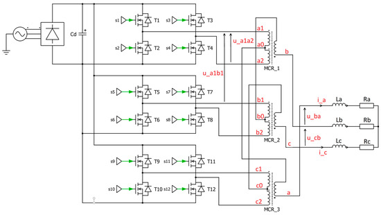
Figure 9.
Scheme of the system used in experimental research.
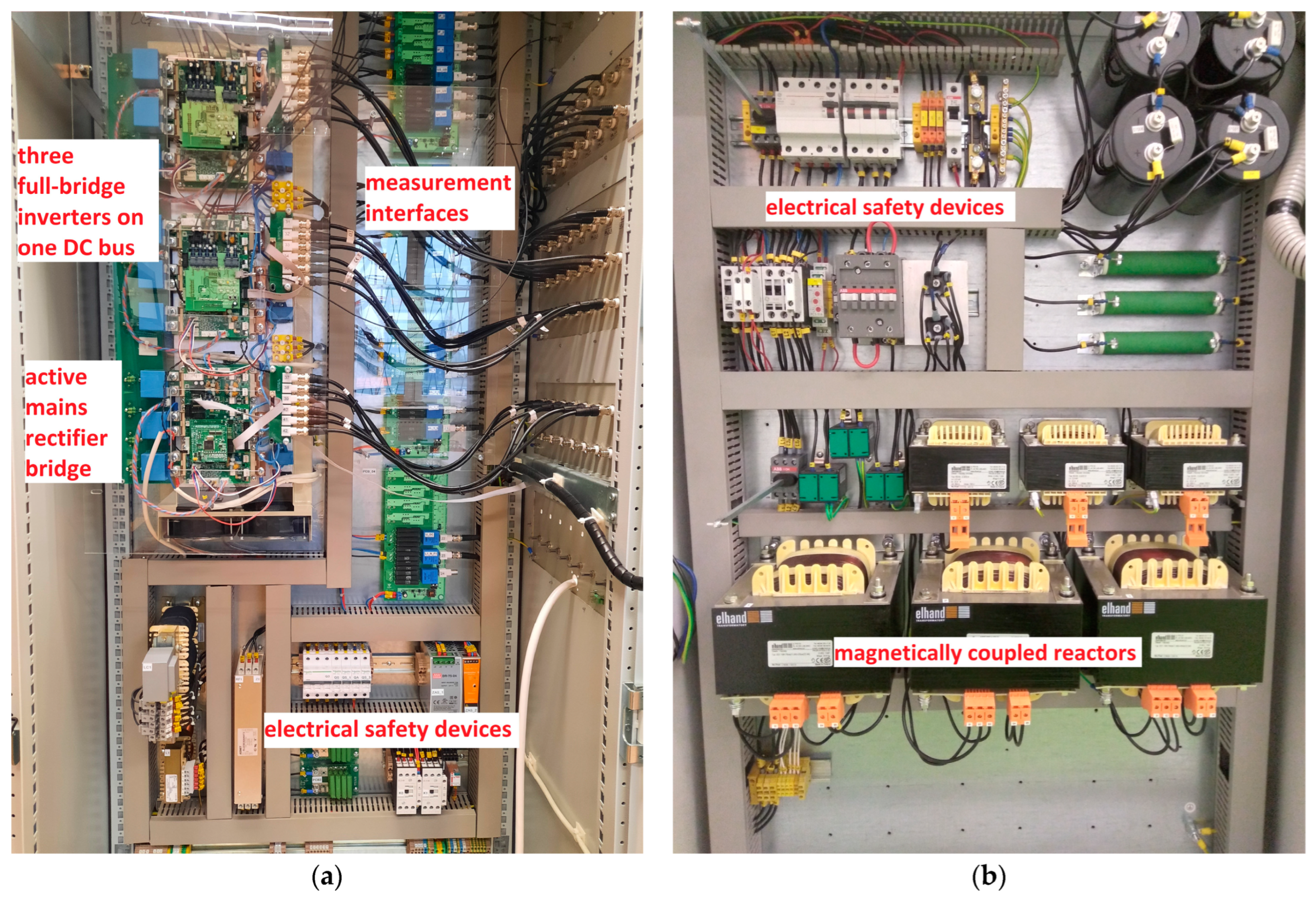
A test stand was adapted for the experiment, using a six-phase inverter on a single DC bus and magnetically coupled reactors in a TDSλ arrangement. The six branches of the inverter made it possible to create three single-phase full-bridge inverters. A photograph of the inverters and magnetically coupled reactors is shown in Figure 10.
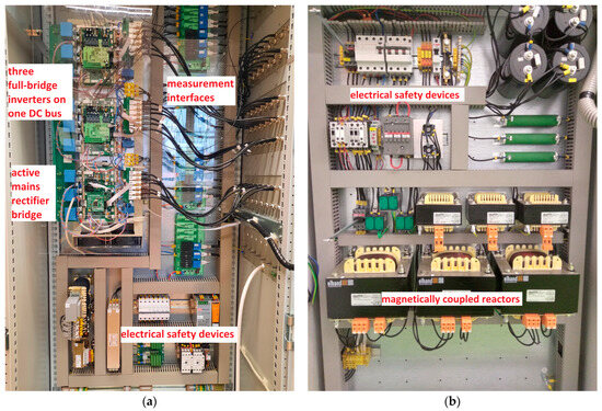
Figure 10.
Photo of three single-phase full-bridge inverters on a common DC bus (a) and photo of magnetically coupled reactors in the TDSλ system (b).
A microprocessor controller was used as a control system, a TI LaunchPadTM kit with C2000TM TMS320F28379D (LAUNCHXL-F28379D), which enabled the control of electronic keys in the inverters.
A Tektronix MSO4104 oscilloscope and voltage and current probes were used for the measurements. The voltage probe was a Tektronix THDP0200, 200 MHz, High-Voltage Differential Probe and the current probe was a Tektronix TCP0030, with ranges of 5 and 30 A, which were used to record voltage and current waveforms. Digital counts were used to record the control signals, using a Tektronix P6516 Logic Probe 16 Channels.
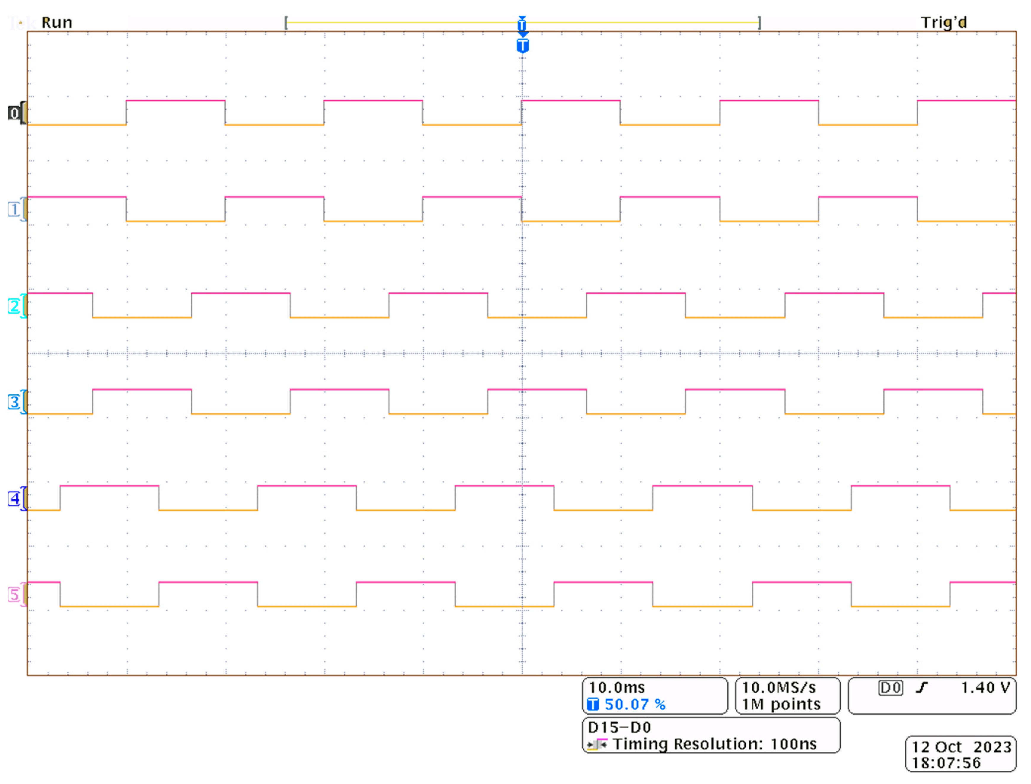
The following oscillograms (Figure 11) show examples of the control signal waveforms recorded for the electronic keys. The waveforms show the control signals for phases a, b, and c.
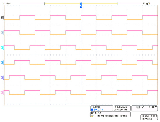
Figure 11.
The oscillograms show the key control signals. The first six waveforms show the control signals labeled s1, s2, s5, s6, s9, s10 (Figure 9).
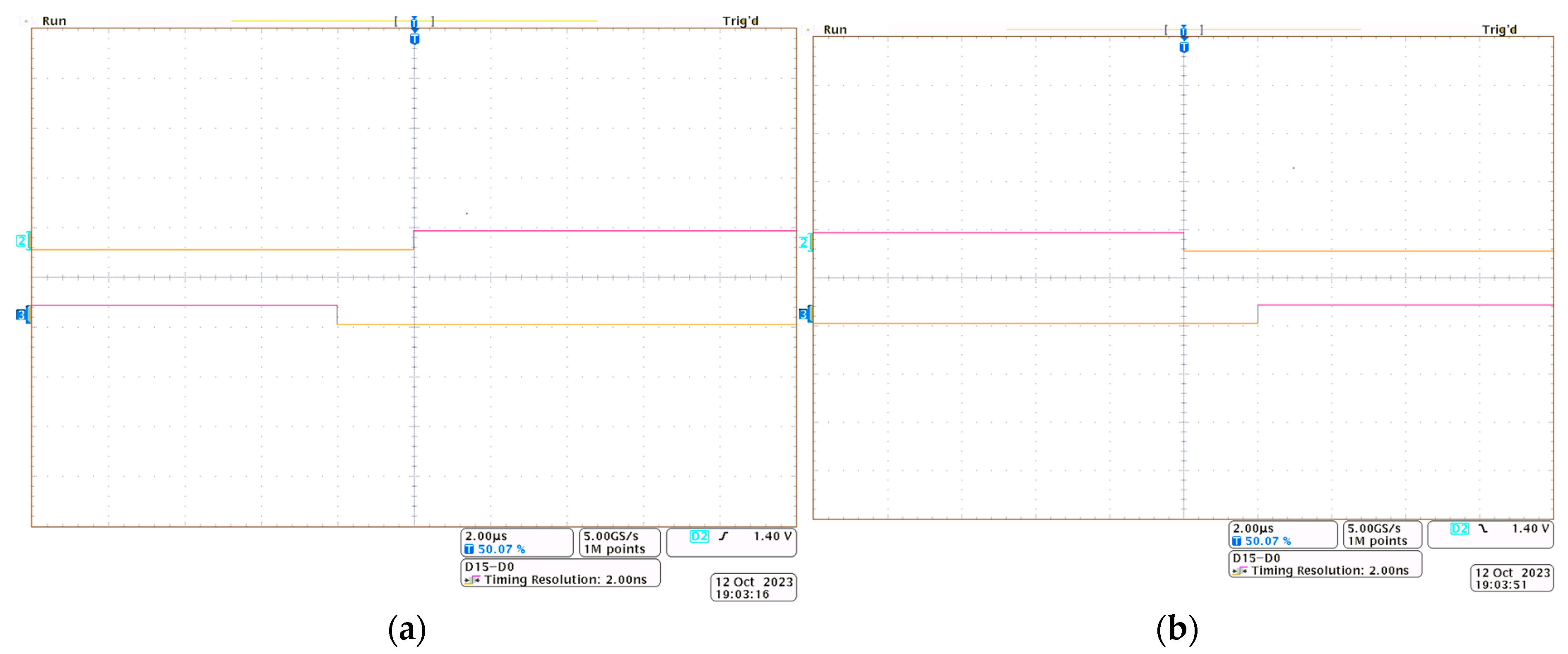
The following oscillograms (Figure 12a,b) show the control signals with the recorded dead time, which is necessary when implementing the adopted control strategy in the laboratory system. For the purposes of the test, the dead time was set to 2 µs.
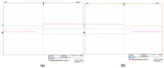
Figure 12.
The oscillograms show the dead time for the electronic key control signals for electronic keys T1 and T2 (Figure 9), where: (a) T1-off/on, T2-on/off; (b) T1-on/off and T2-off/on.
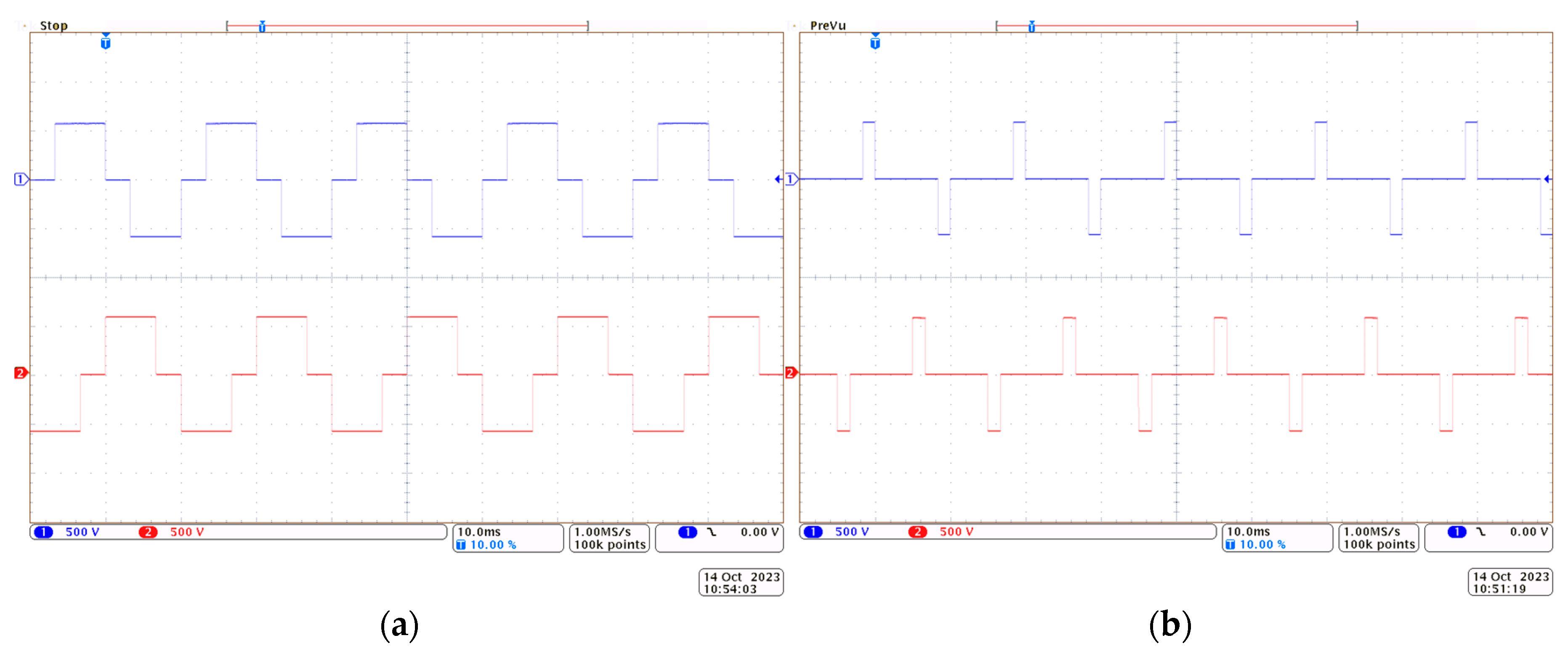
The following oscillograms show the voltage waveforms at the input of the magnetically coupled reactors at points a1-b1 (Figure 13a) and a1-a2 (Figure 13b). These are similar to those obtained in the simulation studies.
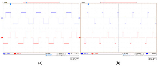
Figure 13.
Oscillograms showing the voltage waveforms at the input of the magnetically coupled reactors: (a) voltage u_a1b1 and (b) voltage u_a1a2.
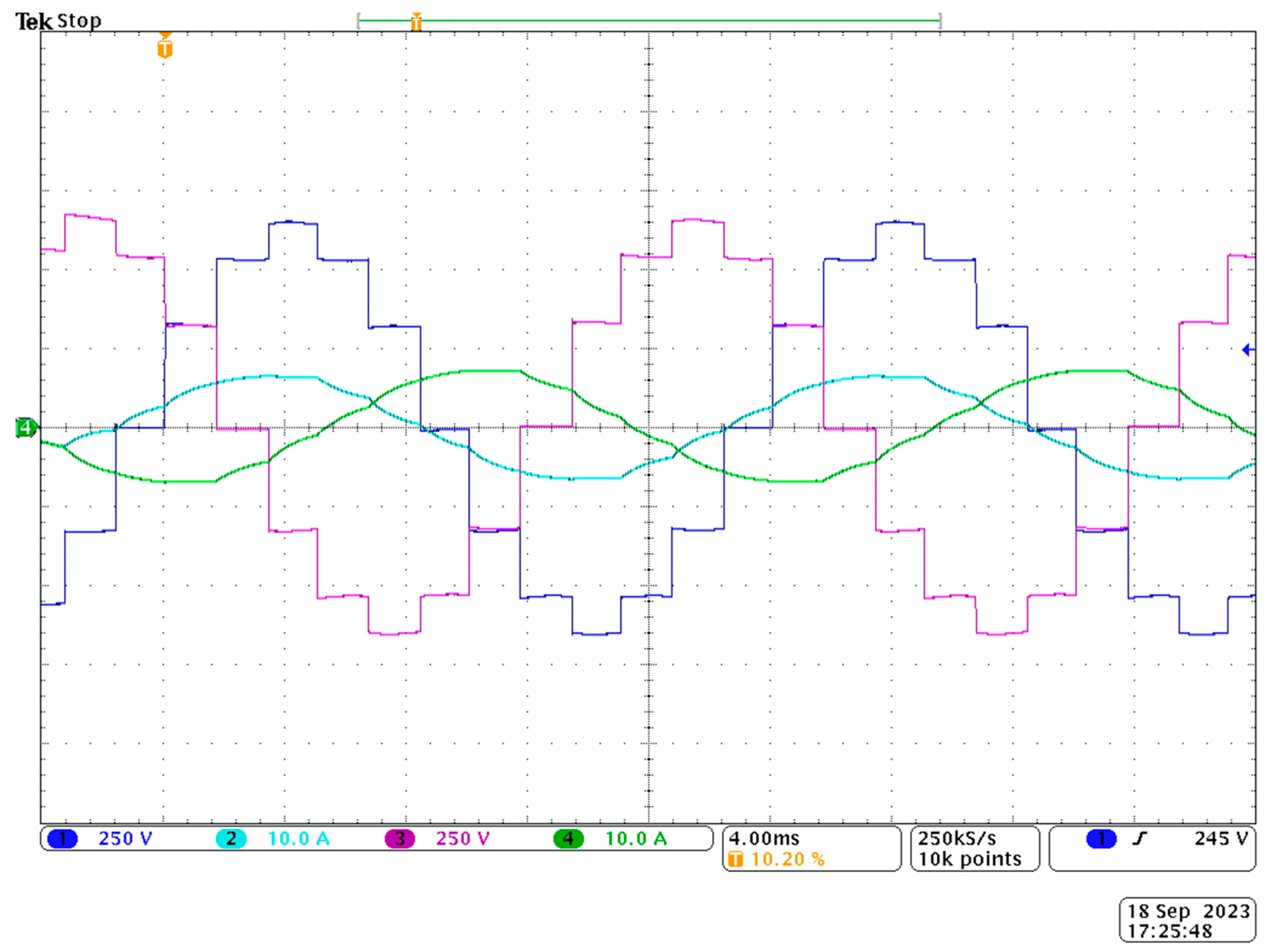
The oscillogram shown in Figure 14 shows the waveforms of output voltages and currents for two phases.
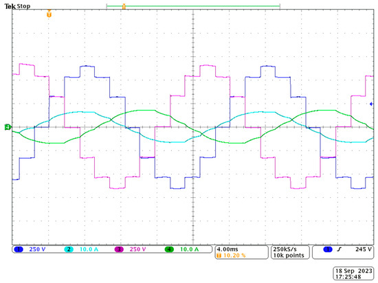
Figure 14.
Oscillograms with the voltage (u_ba, u_cb) and current (i_a, i_c) waveforms for two phases.
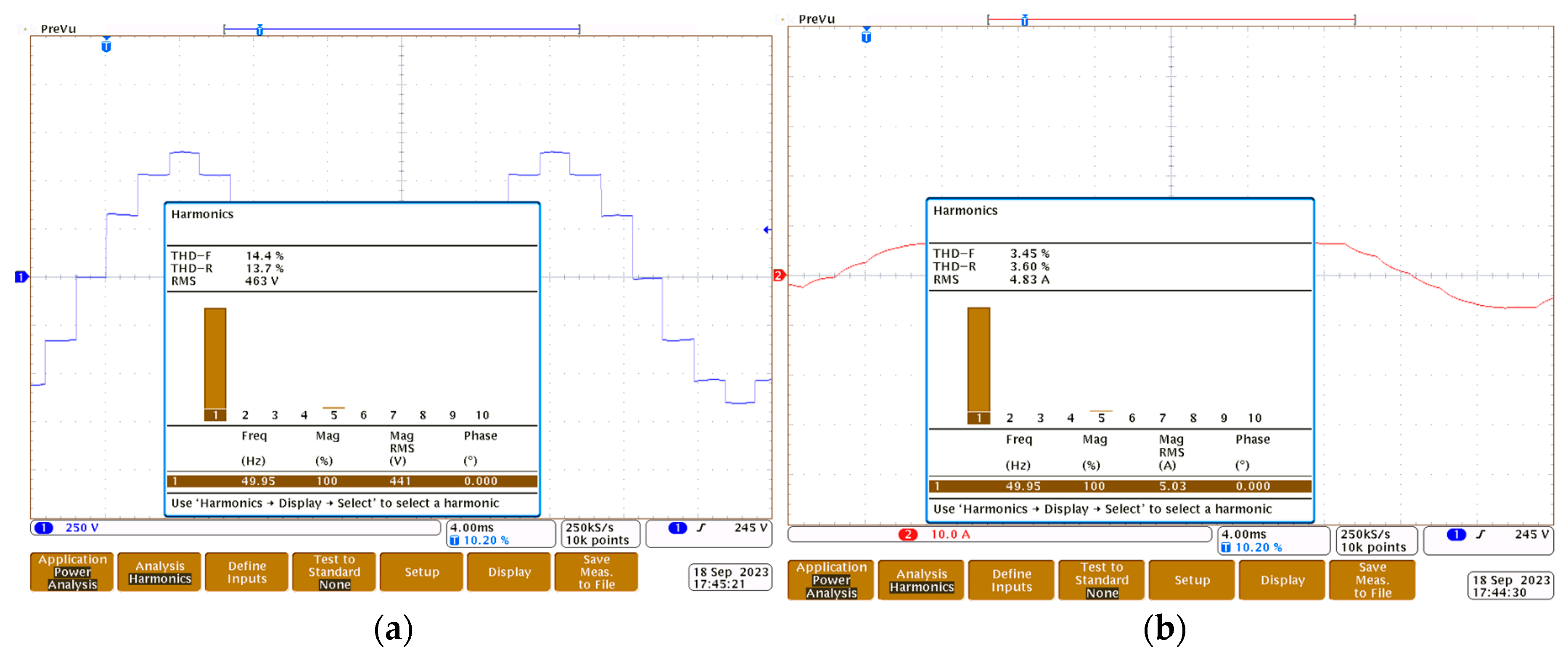
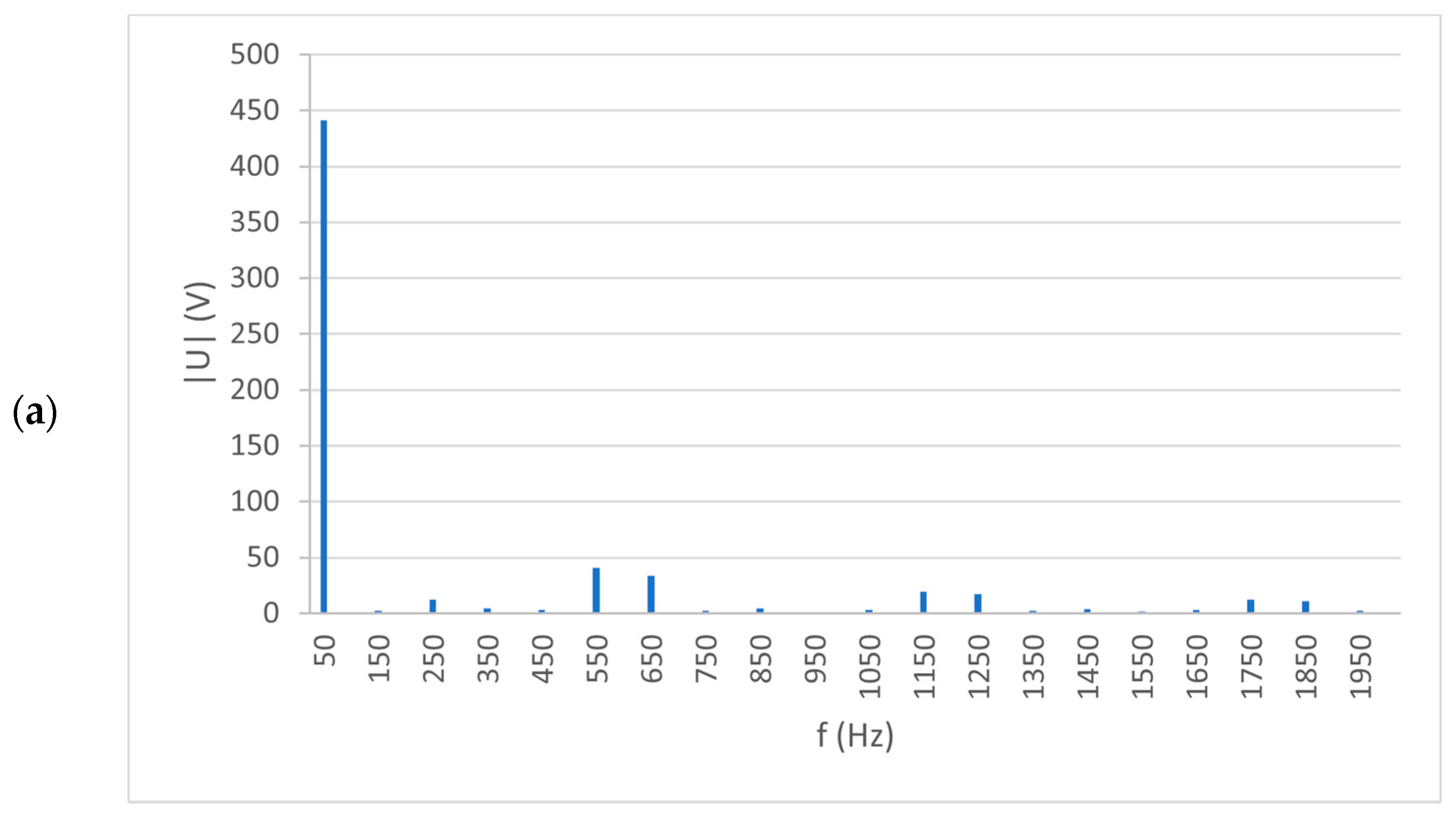
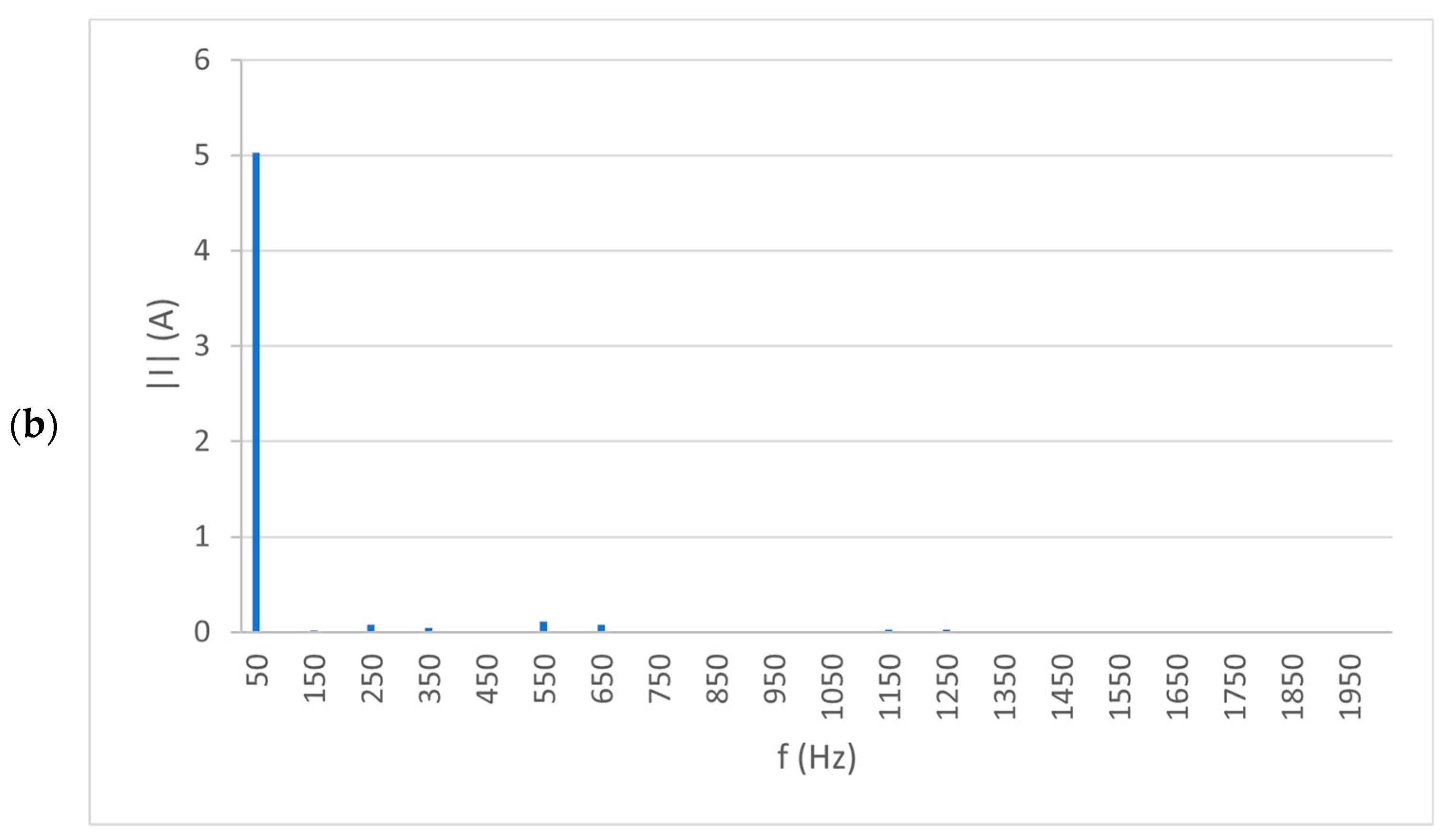
Figure 15a,b show an oscillogram with the voltage and current spectra of one of the phases for the 10th harmonic. As can be seen from this figure, the fundamental harmonic is dominant.
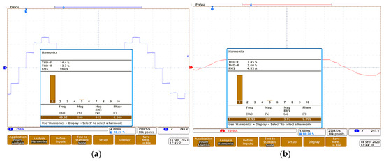
Figure 15.
Oscillograms with the spectra of the selected voltage (a) and current (b) waveforms at the system output.
Figure 16a,b shows, as a supplement, the spectral characteristics on the example voltage and current for the next 40 harmonics. At higher harmonic counts, there is a clear effect of the 11th (10%), 13th (8%), 25th (4.5%), and 25th (4%) harmonics and, to a much lesser extent (less than 2%), the effect of the 3rd, 35th, and 37th harmonics for the output voltages. In the case of currents, none of the higher harmonics represent more than 2%.
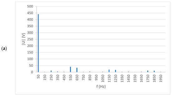
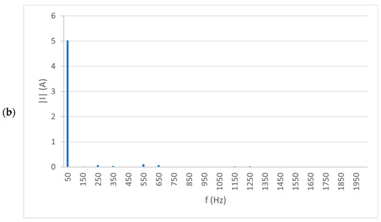
Figure 16.
Spectral characteristics for the selected voltage (a) and current (b) waveforms for 40 harmonics.
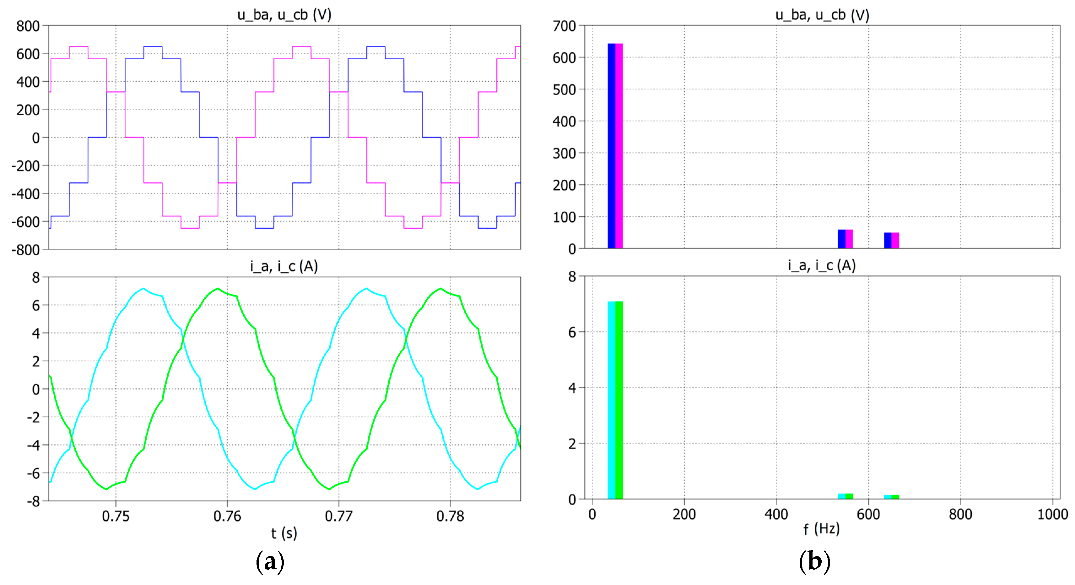
To compare the obtained experimental results with the simulation tests, a simulation was performed for the system in Figure 9 and the same power supply and load values were assumed. The examples of phase-to-phase voltage and current waveforms are shown in Figure 17a, and their spectra are shown in Figure 17b.
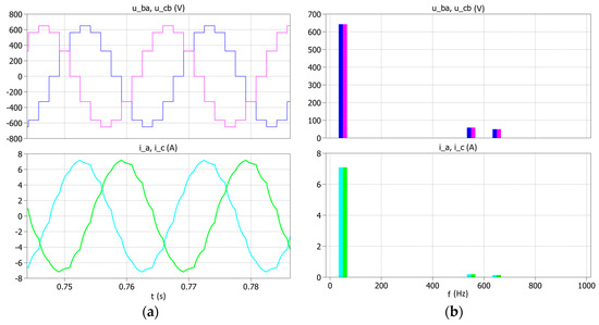
Figure 17.
Examples of the phase-to-phase voltage and current waveforms (a) and their spectra (b) obtained in simulation tests.
The simulation studies carried out are consistent with the results obtained in the experimental studies.
5. Conclusions
During the time of development of various types of microgrids, which are dedicated to ubiquitous renewable energy systems, the presented proposal of a concentrator enabling the connection of single-phase inverters and the conversion of single-phase voltages into a three-phase system seems to be an interesting proposal that also largely solves the problem of energy conditioning due to the reactors used and the multi-level nature of the output voltages. In the described concentrator variants, the single-phase inverter control strategies do not use PWM, which reduces the number of electronic switches and, at the same time, simplifies the control systems. The TDSλ system using magnetically coupled reactors is passive, which does not require the additional power supply and makes it less susceptible to damage.
The presented concepts of a concentrator with single-phase inverters are characterized by high flexibility, because they can be used both for simple cases with three photovoltaic strings and with six photovoltaic strings without major changes in the structure itself.
Capacitive dividers used in concentrators also ensure the elimination of the direct component of current in the power supply circuit.
The described variants of the concentrator with single-phase inverters are characterized by similar investment costs. Both solutions require the use of the same reactor structure and the same number of electronic keys, but the basic difference between them concerns the number of capacitors forming the capacitive divider. In the variant with full-bridge inverters, six capacitors must be used, and in the variant with half-bridge inverters, twice as many capacitors should be used. On the other hand, the variant with full-bridge inverters allows you to handle twice as many photovoltaic strings as the variant with full-bridge inverters.
Comparing the efficiency of both variants, it can be concluded that it is similar, but the variant with full-bridge inverters is more sensitive to changes in the supply voltage than the variant with half-bridge inverters.
An important parameter of the structure under consideration is the dimensional power of the reactors, which strongly depends on the load [6].
The proposed structures of concentrators based on magnetically coupled reactors and single-phase inverters require further research. The experimental tests carried out confirmed some of the obtained simulation results and created the possibility of further expansion of the control system in terms of cooperation with the power grid.
Author Contributions
Conceptualization, A.M.; methodology, A.M., A.K. and P.M.; formal analysis, A.M.; investigation, A.M. and A.K.; writing—original draft preparation, A.M.; supervision, A.M. All authors have read and agreed to the published version of the manuscript.
Funding
This project is financially supported under the framework of a program of the Ministry of Science and Higher Education (Poland) as “Regional Excellence Initiative” in the years 2019–2023, project number 006/RID/2018/19, amount of funding 11,870,000 PLN.
Conflicts of Interest
The authors declare no conflict of interest. The funders had no role in the design of the study; in the collection, analyses, or interpretation of data; in the writing of the manuscript, or in the decision to publish the results.
References
- Bose, B.K. Power Electronics, Smart Grid, and Renewable Energy Systems. Proc. IEEE 2017, 105, 2011–2018. [Google Scholar] [CrossRef]
- Gandoman, F.H.; Ahmadi, A.; Sharaf, A.M.; Siano, P.; Pou, J.; Hredzak, B.; Agelidis, V.G. Review of FACTS technologies and applications for power quality in smart grids with renewable energy systems. Renew. Sustain. Energy Rev. 2018, 82, 502–514. [Google Scholar] [CrossRef]
- Łebkowski, A. Steam and Oxyhydrogen Addition Influence on Energy Usage by Range Extender—Battery Electric Vehicles. Energies 2018, 11, 2403. [Google Scholar] [CrossRef]
- Lamnatou, C.; Chemisana, D.; Cristofari, C. Smart grids and smart technologies in relation to photovoltaics, storage systems, buildings and the environment. Renew. Energy 2022, 185, 1376–1391. [Google Scholar] [CrossRef]
- Eswar, K.N.D.V.S.; Doss, M.A.N.; Vishnuram, P.; Selim, A.; Bajaj, M.; Kotb, H.; Kamel, S. Comprehensive Study on Reduced DC Source Count: Multilevel Inverters and Its Design Topologies. Energies 2023, 16, 18. [Google Scholar] [CrossRef]
- Kumar, G.G.; Krishna, M.V.S.; Kumaravel, S.; Babaei, E. Multi-Stage DC-DC Converter Using Active LC2D Network With Minimum Component. IEEE Trans. Circuits Syst. II: Express Briefs 2021, 68, 943–947. [Google Scholar] [CrossRef]
- Raju, K.N.; Rao, M.V.G.; Raamoorthy, M. Hybrid moulation technique for neutral point claped inverter to eliminate neutral 500 point shift with minimum swithing loss. In Proceedings of the TENCON 2015—2015 IEEE Region 10 Conference, Macao, China, 1–4 November 2015; pp. 1–5. [Google Scholar] [CrossRef]
- Xu, Z.; Zheng, X.; Lin, T.; Yao, J.; Ioinvici, A. Switched-capacitr multilevel inverter with equal distrbution of the capacitors discharging phases. J. Electr. Eng. 2020, 6, 42–52. (In Chinese) [Google Scholar] [CrossRef]
- Yadav, A.K.; Gopakumar, K.; Umanand, L.; Bhattacharya, S.; Jarzyna, W. A Hybrid 7-Level Inverter Using Low-Voltage Devices and Operation With Single DC-Link. IEEE Trans. Power Electron. 2019, 34, 9844–9853. [Google Scholar] [CrossRef]
- Dorn-Gomba, L.; Guo, J.; Emadi, A. Multi-Source Inverter for Power-Split Hybrid Electric Powertrains. IEEE Trans. Veh. Technol. 2019, 68, 6481–6494. [Google Scholar] [CrossRef]
- GOoi, G.H.P.; Maswood, A.I.; Lim, Z. Five-Level Multiple-Pole PWM AC–AC Converters With Reduced Components Count. IEEE Trans. Ind. Electron. 2015, 62, 4739–4748. [Google Scholar] [CrossRef]
- Deepak, P.C.; Rao, S.N. Cascaded H-Bridge Multilevel Inverter Using Inverted Sine Wave PWM Technique. Int. J. Emerg. Trends Electr. Electron. 2013, 6, 39–44. [Google Scholar]
- SLee, S.S.; Chu, B.; Idris, N.R.N.; Goh, H.H.; Heng, Y.E. Switched-Battery Boost-Multilevel Inverter with GA Optimized SHEPWM for Standalone Application. IEEE Trans. Ind. Electron. 2016, 63, 2133–2142. [Google Scholar]
- Sarker, R.; Datta, A.; Debnath, S. A Modified PWM Technique to Reduce Harmonic Content of Multilevel NPC Topology 769 for Medium Voltage Electric Vehicle (EV) Applications. In Proceedings of the Michael Faraday IET International Summit 2020 (MFIIS 2020), Online, 3–4 October 2020; Volume 770, pp. 19–22. [Google Scholar]
- Por, T.R.; Rathd, A.A.; Patil, S.K. Performance Analysis of Cascaded H-Bridge Multilevel Inverter with Variable Frequency ISPWM Technique. In Proceedings of the 2019 Innovations in Power and Advanced Computing Technologies (i-PACT), Vellore, India, 22–23 March 2019. [Google Scholar]
- Muc, A.; Iwaszkiewicz, J. Scalar Voltage-Frequency Control of the OVT Inverter. Prz. Elektrotechniczny 2023, 99, 217–220. [Google Scholar] [CrossRef]
- Muc, A.; Iwaszkiewicz, J.; Piechowski, L. Single-phase Cascade Inverter Controlled by Signals Calculated on the Basis of the Haar Wavelet. Prz. Elektrotechniczny 2023, 99, 232–235. [Google Scholar] [CrossRef]
- Ayadi, F.; Colak, I.; Garip, I.; Bulbul, H.I. Impacts of Renewable Energy Resources in Smart Grid. In Proceedings of the 2020 8th International Conference on Smart Grid (icSmartGrid), Paris, France, 17–19 June 2020; pp. 183–188. [Google Scholar] [CrossRef]
- Jyothi, B.; Pandian, A.; Bhavana, P. Fabrication and experimental analysis of multiple-winding transformers for multiphase supply. Meas. Control. 2020, 53, 662–678. [Google Scholar] [CrossRef]
- Dorazio, T.F. High phase order transmission. In Proceedings of the 1990 IEEE technical conference on Southerntier, Binghamton, NY, USA, 25 April 1990; IEEE: New York, NY, USA. [Google Scholar]
- Zhang, W.; Sandberg, J.; Marneris, I. Multiphase Transformer Effect and Harmonic Response Analysis of Accelerator Power System. IEEE Trans. Appl. Supercond. 2008, 18, 1406–1410. [Google Scholar] [CrossRef]
- Singh, A.; Marti, J.R.; Srivastava, K.D. Circuit reduction techniques in multiphase modelling of power transformers. IEEE Trans. Power Deliv. 2010, 25, 1573–1579. [Google Scholar] [CrossRef]
- Munteanu, A.; Simion, A.; Hagianu, D.A.; Livadaru, L.; Bidei, D. Special three-phase to multiple different polyphase systems electric transformer. In Proceedings of the 2014 International Conference and Exposition on Electrical and Power Engineering (EPE), Iasi, Romania, 16–18 October 2014; IEEE: New York, NY, USA. [Google Scholar]
- Abdel-Khalik, A.S.; Elserougi, A.; Shafik, Z.; Ahmed, S.; Massoud, A. A Scott connection-based three-phase to five-phase power transformer. In Proceedings of the 39th Annual Conference of the IEEE Industrial Electronics Society (IECON’2013), Vienna, Austria, 10–13 November 2013; IEEE: New York, NY, USA. [Google Scholar]
- Detka, K.; Górecki, K.; Grzejszczak, P.; Barlik, R. Modeling and Measurements of Properties of Coupled Inductors. Energies 2021, 14, 4088. [Google Scholar] [CrossRef]
- Górecki, K.; Detka, K. Analysis of influence of losses in the core of the inductor on parameters of the buck converter. In Proceedings of the 2018 Baltic URSI Symposium (URSI), Poznań, Poland, 14–17 May 2018; IEEE: New York, NY, USA, 2018; pp. 129–132. [Google Scholar]
- Górecki, K.; Detka, K.; Kaczerski, K. The Influence of the Transformer Core Material on the Characteristics of a Full-Bridge DC-DC Converter. Energies 2022, 15, 6160. [Google Scholar] [CrossRef]
- Meier, H.U. Combining Inverters for Harmonic Reduction. US Patent 3792286, 2 December 1974. [Google Scholar]
- Depenbrock, M.; Niermann, C. Netzfreundliche Gleichrichterschaltung mit netzseitiger Saugdrossel (NSD)—Teil I: Theorie der Wechselspannungsverhältnisse. ETZ-Archiv 1989, 11, 241–243. [Google Scholar]
- Depenbrock, M.; Niermann, C. A New 12-Pulse Rectifier Circuit with Line-Side Interphase Transformer and Nearly Sinusoidal Line Current. In Proceedings of the 6th Conference on Power Electronics and Motion Control, Budapest, Hungary, 1–3 October 1990; pp. 374–378. [Google Scholar]
- Mysiak, P. A 24-pulse diode rectifier with coupled three-phase reactor. ISSN 0253-3839, National Taiwan University of Science and Technology. J. Chin. Inst. Eng. 2007, 30, 1189–1204. [Google Scholar]
- Iwaszkiewicz, J.; Muc, A.; Mysiak, P. A 12-pulse rectifier using coupled reactors for supplying three-inverters. Renew. Energy Power Qual. J. 2019, 17, 589–592. [Google Scholar] [CrossRef]
- Iwaszkiewicz, J.; Muc, A.; Mysiak, P. 18-pulse rectifier in arrangement with coupled three-phase reactor. Renew. Energy Power Qual. J. 2019, 17, 393–397. [Google Scholar] [CrossRef]
- Ourahou, M.; Ayrir, W.; EL Hassouni, B.; Haddi, A. Review on smart grid control and reliability in presence of renewable energies: Challenges and prospects. Math. Comput. Simul. 2020, 167, 19–31. [Google Scholar] [CrossRef]
Disclaimer/Publisher’s Note: The statements, opinions and data contained in all publications are solely those of the individual author(s) and contributor(s) and not of MDPI and/or the editor(s). MDPI and/or the editor(s) disclaim responsibility for any injury to people or property resulting from any ideas, methods, instructions or products referred to in the content. |
© 2023 by the authors. Licensee MDPI, Basel, Switzerland. This article is an open access article distributed under the terms and conditions of the Creative Commons Attribution (CC BY) license (https://creativecommons.org/licenses/by/4.0/).

