Abstract
The article analyzes the modern theory and practice of transportation and storage of compressed natural gas. The expediency of the inclusion of a floating storage berth for the loading of gas carriers and container ships into the infrastructure of marine transportation of compressed natural gas is considered. Requirements for storage berth are formulated. It is shown that without using a marine mooring storage facility, the loading time of a gas carrier will considerably increase, and the economic efficiency of compressed gas transportation will lower due to the considerable time of loading and unloading of a gas carrier. The construction of a storage berth is proposed, and calculations of storage parameters and calculation of its buoyancy are made. The possibility of using the REFPROP vs. 9.1 software package to automate the selection of the composition of a multicomponent hydrocarbon mixture for further use at the selected range of temperatures and pressures is substantiated. The use of the system is considered in the example of phase equilibrium of a multicomponent hydrocarbon mixture.
1. Introduction
In recent years, transportation of compressed natural gas (compressed natural gas—CNG) by specialized gas carriers, especially for distances from 250 to 1500 nautical miles, has been considered as an alternative to the transportation of natural gas by sea in the form of liquefied natural gas (LNG) and through offshore pipelines. This is cheaper than LNG transportation (taking into account the high costs of construction of LNG plants and terminals) and pipeline transportation (Figure 1) [1,2].
It should be noted at the outset that the compressed gas production and transportation industry is not perceived as an alternative to the liquefied natural gas (LNG) industry. There are opportunities in the global gas market for the effective application of both technologies in different market segments.
The study of problems of sea transportation of CNG and its storage at different times was carried out by the following authors: Vovk V.S., Novikov A.I., Glagolev A.I., Orlov Y.N., Udalov D.A., Votintsev A.V., Blinkov A.N., Vlasov A.A., Adamovich B.A., Svann Fillip L. Dzh., Terry R. McBride, Demeshko G.F., Pronin E.N., Podenok S.E., Wasserman A.A., Wagner J.V, Wagensveld S.V., Stenning D.G., Cran J.A., Patel H.N., Rynn P.L., Economides M.J., Dunlop J.P., Wood D.A., Mokhatab S.B., Broeker R.J., Nassar Y.M. et al. [3,4]. The research carried out by these authors focuses on analyzing the basic elements of the nascent compressed natural gas (CNG) transportation industry [5,6]. Within the framework of their work, an analysis of prerequisites for the development of CNG marine transportation and storage is provided, foreign technologies and modern projects of CNG transportation and storage are given, economic aspects of the implementation of such projects are analyzed, and models for estimation of the comparative efficiency of marine transportation of liquefied and compressed natural gas are proposed [7,8].
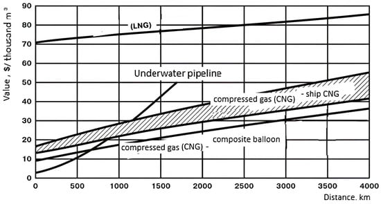
Figure 1.
Comparative tariffs for natural gas transportation [9].
The following foreign companies are most focused on the development of compressed natural gas marine transportation systems: EnerSea Transport LLC (Houston, TX, USA), USA; Knutsen OAS Shipping (Haugesund, Norway); Compressed Energy Technology AS (CETech) (Stavanger, Norway); TransCanada Pipeline Ltd. (Calgary, AB, Canada); Trans Ocean Gas Inc. (TOG) (St. John’s, NL, Canada); Sea NG Management Corporation (Calgary, AB, Canada) (Figure 2 and Figure 3) [9,10]. Each of the companies has conceptual designs of CNG vessels that have been approved (Approval in Principal) by DNV or ABS (American Classification Society classification societies [11,12].
CNG ships designed by the companies will have a capacity from 3 to 33 mln m3 of natural gas. As conceived by the developers, high-capacity vessels are intended for servicing large projects with a route length of 2000–2500 nautical miles [13]. Ships of small tonnage are to operate on short local routes [14,15].
In terms of basic shipbuilding parameters, CNG vessels will be, to a large extent, similar to modern LNG vessels. The principal dimensions of CNG vessels will be in the range of 280–320 m length, 55–60 m beam, 13.5–14.5 m. The full speed of CNG vessels will be 17.5–18.0 knots [16,17].
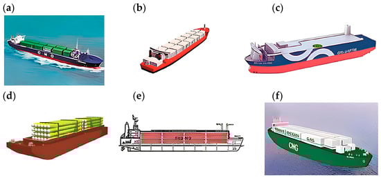
Figure 2.
CNG vessel projects of foreign companies [18,19]: (a)—EnerSea Transport LLC, CШA; (b)—Knutsen OAS Shipping, Hopвeгия; (c)—Compressed Energy Technology AS (CETech), Hopвeгия; (d)—TransCanada Pipeline Ltd., Kaнaдa; (e)—Sea NG Management Corporation, Kaнaдa; (f)—Trans Ocean Gas Inc. (TOG), Kaнaдa.
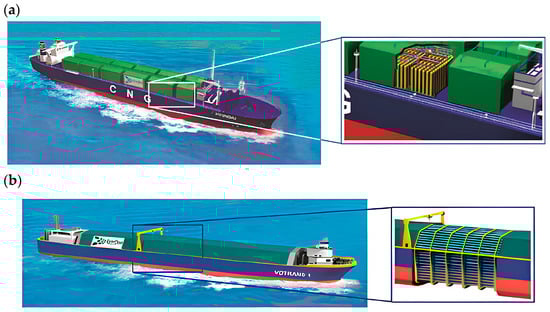
Figure 3.
Tanker for CNG transportation based on VOTRANS technology: (a)—with vertical tanks, (b)—with horizontal tanks [9,20].
The gas is transported on the ship in containers or pipes at high pressure at ambient temperatures or when cooled down to −50 °C. This saves the construction of costly liquefaction plants, which are usually located on the seashore. The compressor plant can be located either onshore or on the ship itself. This makes it possible to develop small and medium-sized fields more profitably and environmentally friendly, as well as gas condensate from gas condensate fields and associated gas from oil fields.
Today, there is a need to diversify gas supply routes [21,22]. When designing large-capacity gas carriers, it is important to take into account considerations of ensuring a high service life. The high cost of the ships must be compensated by a long period of intensive accident-free operation, which aggravates the problem of maintaining the fatigue strength of the structure, in particular, to a much greater extent (twice as much or more) for ice-sailing ships. It is necessary to take care of deck equipment for vessels of northern and ice navigation with a view to prolonged service life [23,24].
Thus, the main advantage of CNG transport over LNG transport is that expensive liquefaction plants, storage facilities, and regasification plants need not be built [14,25]. The storage facility is the vehicle itself—the ship—and the gas is injected using a compressor station, which can be installed both onshore and on the ship itself. To pay for the creation and transport of LNG, a large field and its development over 25 years is required.
According to the authors, sea transportation of CNG for the period of transportation involves raising its pressure to values of 175–275 bar when its density rises to 300 times. In this state, gas is transported on special CNG ships equipped with special high-pressure tanks, most often of cylindrical shape, made mainly of standard steel pipes (of high-strength steels, for example, X-70, X-80, X-90 type). The production of these pipes for gas transmission companies is well established, also in Russia. Such cylindrical cylinders have to be placed vertically or horizontally on the CNG vessel [15,26] (Figure 4).
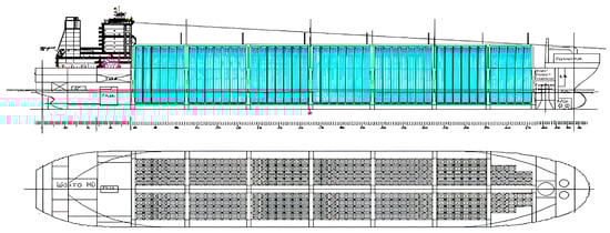
Figure 4.
Schematic arrangement of cylindrical cargo cylinders on a CNG vessel when installed in an upright position [13].
But despite the great interest shown in recent years in transporting compressed natural gas on the sea surface using gas carriers and container ships (Coselle and Vortrans technology), there are mostly only conceptual designs of ships to implement the technology [27,28]. One of the reasons for this is, in our opinion, the lack of attention to fast-loading technology for gas carriers with multiple compressed gas tanks [29].
The relevance lies in the fact that due to political, economic, and technological risks, as well as insufficient attention to the technology of fast loading of gas carriers with numerous tanks, there is a need for a method of transportation of CNG. The method of loading/unloading at sea is of the greatest interest. In this connection, a conceptual design of a floating storage berth with a capacity of 50–100 million m3 of gas is proposed. The use of the storage facility will reduce uneven gas withdrawal from the main gas pipeline (off-take), eliminate peak loads on the gas compression system, and accelerate the loading of CNG vessels. In addition, the storage facility cools the gas, so its capacity increases [9].
The objective of the article is to justify the possibility of the application of compressed natural gas floating storage with a high-pressure supply pipeline for fast loading of ships with CNG, to increase volumes of transported gas, to reduce technological and environmental risks, as well as to justify the selection of multicomponent hydrocarbon mixtures, such as CNG.
In order to achieve the set goal, the following tasks are solved:
- -
- to analyze available research and development in the field of marine transportation and storage of CNG;
- -
- to consider CNG gas carrier ships;
- -
- calculate the parameters of the storage facility;
- -
- to give recommendations on the use of marine storage.
2. Materials and Methods
Within the framework of scientific work, the authors analyzed similar projects and their non-disadvantages calculated parameters of the proposed storage [30,31]. And also the calculation of parameters of CNG storage in the program complex REFPROP [32].
COSELLE technology is known—US patent No 5839383 [2]. Describes the storage of compressed natural gas in a continuous pipe coiled into loops and layers and contained in a natural gas transport container. This technology is based on the transport of compressed gas at 275 atm in special coils with tubing.
The unit is designed to be placed in specialized gas carriers. The disadvantage of the system is that the method of arrangement of radial coiling of tubes on a spool (cassette) implies the occurrence of high stresses in the tube body, which reduces the service life. Also, this device is not corrosion-proof, with no corrosion protection.
The patented and approved by the ABS technology for transportation of compressed natural gas by EnerSea (US Patent No. 5803005—VOTRANS) involves the transport and storage of CNG in horizontally or vertically arranged large diameter pipes (Figure 3) [7,28]. The disadvantage of the system is increased metal consumption, the need for a large number of stop and control valves for each cylinder, the labor intensity of defectoscopy of pressure vessels, and the lack of the possibility of individual gas drying.
Transport of compressed gas in vertical or horizontal tanks-cylinders at a pressure of 90—130 atm and temperature of −20 ÷ −40 °C considered in the US patent No. 5207530 [21]. The low-temperature results in an increased density of compressed gas. A CNG vessel contains around 100 tube modules with a height of h = 24–36 m. Each module consists of 24 tubes of 1 m diameter. The total capacity of the vessel is 5.6–5.7 million m3 of CNG.
The disadvantage is that the system requires many additional and expensive components (e.g., use of refrigerated vessels) and is not suitable for on-site storage of large quantities of gas [33,34].
A method of storing natural gas and a device for its implementation (patent RU No. 2263248) for meeting peak gas demand is known [35]. The use of the invention will make it possible to store gas compressed to 400 atm in modular thin-walled tanks. The disadvantage is that composite-reinforced polyethylene is used for storage, the reliability of which in long-term operation has not been proved.
Also known as an installation for storing natural gas in pipes containing means for compressing natural gas; means for expanding natural gas; one or more fully enclosed storage systems in steel pipes for compressed storage of natural gas; means for holding gas inside said storage systems in steel pipes and controlling the flow in and out of said systems contains an injection valve, a holding valve and a delivery valve [36,37]. The disadvantage is the difficulty of transportation and the cost to move to consumers.
In turn, the authors propose a technical solution, which is that the use of a floating storage berth will reduce the unevenness of gas withdrawal from the main gas pipeline (off-take), eliminate peak loads on the gas compression system, and accelerate the process of CNG ship loading.
The basic concept of CNG technology involves compressing natural gas from a supply line or storage facility at a special compressor facility before loading it onto a specialized ship [38]. The key role here is played using two main parameters of the gas loaded on the ship: its temperature and pressure and their derivative—density, the increase of which is proportional to the value of overpressure compared to natural conditions [17,39].
Specialized ships, barges, and container ships deliver compressed natural gas to the receiving terminal. Mixtures of hydrocarbon gases (methane-gas condensate, methane-diesel fuel, etc.) allow to increase heat capacity [9,40].
In order to ensure the single-phase liquid state of hydrocarbons, it is necessary to choose the right parameters of transportation and storage: pressure P and temperature T. For this purpose, it is necessary to study the phase state of the hydrocarbon system by determining the critical parameters (critical pressure and critical temperature).
The authors’ studies use the purchased licensed specialized thermodynamic library of TFS and FR REFPROP [2,41]. Both thermodynamic properties and their derivatives, as well as transport properties (viscosity, thermal conductivity, surface tension, dielectric constant, and the higher and lower heat of combustion), are calculated (Figure 5) [42,43].
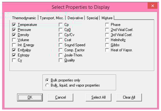
Figure 5.
Substance properties selection dialog box in the REFPROP.
The authors [44] analyze the applicability of the REFPROP software package for the automation of phase state studies of multicomponent hydrocarbon systems.
3. Results
3.1. Requirements for Compressed Gas Storage Berth
Based on the analysis of Russian and foreign conceptual designs of gas carriers for the transportation of compressed natural gas, the following requirements for a repository-berth are formulated [45,46].
- (1)
- Storage-berth for compressed natural gas (hereinafter referred to as «storage») should be located at least 1500 m away from seaport infrastructure and other oil and gas storage facilities (including LNG, gasoline, NGL, diesel fuel, etc.). The distance from the storage facility to the nearest facilities should comply with safety standards for the storage of a similar volume of LNG [47].
- (2)
- The volume of gas contained in the storage facility should be capable of simultaneously fuelling two COSELLE or VOTRANS vessels (20 million m3), a containerized gas carrier, or with a 20% reserve of 50 million m3. Gas pressure in storage tanks should not be less than the pressure in the tanks of COSELLE gas carriers or 275 atm.
- (3)
- Filling of each vessel’s CNG tanks should be performed simultaneously [48,49].
- (4)
- The storage facility can be used as a mooring facility for two CNG vessels at the same time.
- (5)
- The duration of each vessel’s CNG loading shall not exceed 48 h, and the duration of unloading shall not exceed 24 h.
- (6)
- Compressed gas shall be stored in steel (or composite) pipes isolated from ambient and seawater at 300 atm. The pipes shall be arranged in transverse layers, interconnected using high-pressure pipelines, and contain controllable safety and shut-off valves and devices for technical diagnostics.
- (7)
- The diagnostic tools should ensure the technical condition of the storage facility is monitored during its operation.
- (8)
- Measures should be provided to protect against fire and explosion, shrapnel, etc. [50,51].
- (9)
- The storage shall have variable buoyancy stability and shall be capable of being towed from the place of manufacture to the yard and, for repairs and other operations, shall have interchangeable pontoons and attachments.
- (10)
- The storage shall be filled with gas from a high-pressure double-stranded pipeline providing the required capacity via a booster compressor equipped with diagnostic facilities [52,53].
- (11)
- Provision should be made for filling the storage facility with both natural gas and methane-based energy gas mixtures. For this purpose, the next paragraph deals with the selection of blends of multicomponent hydrocarbons and the influence of the composition on the parameters (temperature and pressure) of their storage and transportation [54,55].
In the present paper, we will limit ourselves to a conceptual design of a CNG storage facility. The detailed design of the storage facility will be performed later in the detailed design.
3.2. Design of the Storage Facility
The developed apparatus concerns the field of compressed natural gas storage and can be used for its accumulation, storage, and discharge (Figure 6).
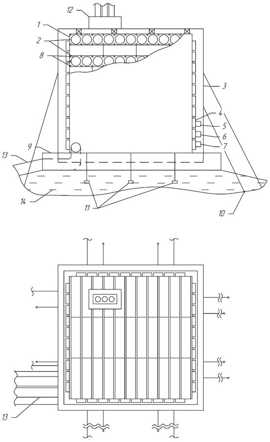
Figure 6.
Schematic diagram of CNG storage berth. 1—Gas storage facility; 2—Pipe assembly; 3—Kevlar coated support structure; 4—High pressure gas mains; 5—Equalisation valve; 6—Pressure relief valve; 7—Check valve; 8—Flame retardant gas pipes; 9—Weighting base; 10—Anchor system; 11—Aluminum-magnesium protectors; 12—Compressor; 13—Supply gas pipeline; 14—Water.
An appliance for storage of compressed natural gas at sea (marine storage) containing steel and/or composite pipes, tanks, or other tight reservoirs in which natural gas or a mixture of hydrocarbons is accumulated under pressure in the range of 50–300 atm, devices for hydrocarbons injection and discharge; what is remarkable in that in order to increase safety of storage and reduce area and volume occupied by storage, it is placed on the sea bottom, under or on the surface of sea or other reservoir at safe distance from ports. The design features of the CNG storage facility are summarized below.
- (1)
- Storage is divided into blocks (2) (layers) with the horizontal and mutually perpendicular arrangement of pipes in layers; the blocks are connected using high-pressure gas mains (4) with equalizing (5), safety (6) and check (7) valves, which provide maintenance of discharge pressure, maximum emptying of pipes with gas, and the capacity of gas in each layer is at least two times higher than the capacity of gas in the transported ship module [56,57].
- (2)
- Each storage layer is connected using a high-pressure line to the transport tanks (13).
- (3)
- Pipes or other devices (8) containing pressurized flame retardant gas (e.g., carbon dioxide) are placed between the pipes in the layer.
- (4)
- To ensure stability and to enable the device to move under or over the surface of the sea or other body of water, the marine storage shall contain removable weighing devices and anchoring systems to anchor (10) it to the bottom of the body of water.
- (5)
- Each pipe layer is connected to a gas loading/unloading device (12), which can be either vertical pipes or STL (submerged turret loading) buoys connected to compressed gas onshore storage facilities, trunk pipelines, vessels, or compressed gas containers.
- (6)
- In order to protect against corrosion, it contains a system of anode protection, e.g., in the form of aluminum-magnesium protectors (11) connected to each layer by electrical bonding, ensuring a negative potential of 0.6–0.8 V in each layer.
- (7)
- Each pipe layer is connected using high-pressure lines (4) to the natural gas source (pipeline, underground storage facility) and high-pressure compressor, and the high-pressure compressor can be located on the device itself.
- (8)
- Storage has variable buoyancy and contains means for changing its location in the vertical direction and means for autonomous movement within the water area of a seaport.
- (9)
- The device is coupled to a high-pressure booster compressor, which ensures that the pressure in the device is maintained as the tubes are emptied.
- (10)
- The surface of the repository is protected from debris in the event of a device explosion by Kevlar or other protection.
The storage facility shall consist of steel tanks for the storage of CNG 1. The CNG storage tanks are divided into blocks 2 and covered with Kevlar 3. The blocks are connected to each other by high-pressure gas lines 4 with equalization 5, safety 6, and check valves 7. Tubes 8, containing pressurized flame retardant gas, are placed between the tubes. The units themselves are connected to a weighted base 9. On the side, there are removable anchor systems to anchor the storage unit to the bottom of the reservoir 10. In order to protect against corrosion, aluminum-magnesium protectors 11, electrically bonded to each layer, are used. At the top of the reservoir, there is a gas injection and discharge device (high-pressure booster compressor) 12. At the bottom, there is a double-strand gas supply pipeline 13.
Natural gas, with a pressure 50–100 atm, goes to booster compressor 12 where it is pressurized to the required pressure (300 atm). Natural gas from the booster compressor under the pressure of 300 atm. comes to the marine gas storage 1 via high-pressure lines 4, the rated capacity of which is assumed to be 50 mln m3 of gas at a pressure of 1 atm., or 17 thou. M3 of compressed gas. Such capacity allows simultaneously fuelling two vessels with 20 mln m3 CNG. Pipes in the storage are located horizontally, and pipes in every layer 2 (or group of layers) are connected with each other using high-pressure lines 4 and represent a single vessel, and layers are mutually perpendicular to each other. Each pipe layer is connected to piping 4, which provides the required pressure in the pipes. As the pressure decreases (critical decrease is 10%), compressor 12 is started, which again increases pressure to nominal. In this way, the number of tanks on the vessel equal to the number of pipe layers is filled at the same time. The process ends when the transport tanks on the CNG ship are filled with gas at the required pressure.
A schematic of the storage device is shown in Figure 7.
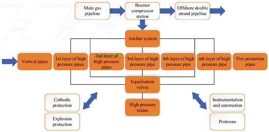
Figure 7.
Scheme of the storage facility construction [9].
3.3. Storage Parameters
Calculation of the number of pipes in the storage [9].
Input data:
Vst = 50 mln m3;
D = 1220 mm;
t = 39 mm;
p = 275 atm.
- Volume of natural gas at 1 atm., which falls on 1 m of pipe:
- 2.
- Volume of compressed gas per 1 m of pipe:
- 3.
- The storage volume by convention is 50 million m3, so the total length of all pipes will be:
- 4.
- Calculate the total number of pipes in each layer and the height of the storage.
The longitudinal pipes layer has a length of 96 m:
The cross pipes layer with a length of 48 m accounts for:
Total length of longitudinal pipes of one layer:
The total length of the cross pipes of one layer is the same:
The number of storage tube layers will be:
Then, the height of the storage facility will be:
Thus, storage of compressed gas (methane) is carried out in steel pipes. The external diameter of the pipes is 1220 mm, the wall thickness is 39 mm, the internal diameter is 1142 mm, and the length of the section is 12 m. Weight of one pipe without insulation—744.43 kg. Internal cross-sectional area—0.431 m2. Dimensions of the storage facility: length—100 m, width—50 m, height—60 m. The total length of the pipes in the storage facility—177.506 km. Estimated storage capacity of 50 million m3 (including COSELLE or VOTRANS mooring for 2 CNG vessels). The design gas pressure is 275 atm (Table 1).

Table 1.
Storage parameters.
Table 2 summarises the technical characteristics of the pipes that make up each layer of the projected storage facility.
Table 2.
Technical specifications of the pipes.
Drawing of the storage in two views in the next section.
Calculation of the buoyancy of the storage tank [9].
Volume of the storage tank (including high-pressure lines):
Mass of all pipes:
The force of gravity acting on the storage:
Since the ejection force is greater than gravity, the storage vessel will float. An anchoring system is provided to keep it on the bottom.
3.4. Rationale for Selection of Hydrocarbon Mixtures for Their Transportation and Storage
The research was conducted for CNG; component composition is presented in Table 3. The analysis of phase states of hydrocarbon mixtures at low temperatures was carried out for pumping and storage [58,59].
Table 3.
Component composition of the multicomponent hydrocarbon mixture used in this study.
Phase diagram P-T (pressure-temperature) of the multicomponent hydrocarbon mixture (Figure 8) constructed in REFPROP vs. 9.1 [60,61]. Figure 9 shows a tabular variation of phase states of a mixture of hydrocarbons at different temperatures T1 = −55 °C, T2 = 0 °C, and T3 = 55 °C as the pressure changes [62,63].
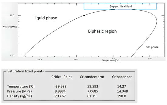
Figure 8.
Pressure-temperature diagram of a hydrocarbon mixture, determination of critical parameters of a multicomponent hydrocarbon mixture of a given composition.
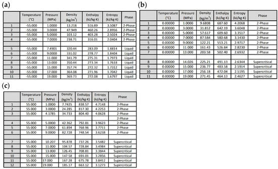
Figure 9.
Tables of phase state changes of a model mixture of hydrocarbons at T1= −55 °C (a), T2 = 0 °C (b), and T3 = 55 °C (c) when varying pressure.
Thus, this study of phase states of multicomponent hydrocarbon mixtures using the numerical experiment method allows to refuse a large number of laboratory tests, as well as to determine changes in the parameters of hydrocarbon mixtures depending on the composition of the pumped mixture and determine these parameters for further transportation. In further studies, we will consider changes in the thermal properties of multicomponent hydrocarbon mixtures depending on their composition [64].
4. Conclusions
The following results have been achieved in the process of accomplishing the work:
- Existing research and developments in the field of CNG transportation and storage are analyzed, and CNG carrier ships are considered.
- Technical solutions for marine transportation of compressed natural gas and its storage have been proposed.
- Calculations of storage of compressed gas have been made; requirements for offshore storage are formulated.
- The study of phase states of multicomponent hydrocarbon mixtures using the method of numerical experiment allows to refuse a large number of laboratory tests, as well as to determine the change of parameters of hydrocarbon mixtures depending on the composition of the pumped mixture and to determine the parameters (pressure and temperature) for further transportation.
- Recommendations for the use of storage are given.
With a number of competitive advantages, natural gas is becoming one of the most popular primary energy sources. The development of compressed natural gas production and transportation technologies opens up new niches for natural gas applications. Following a review of the promising applications of offshore compressed natural gas transportation, great opportunities for CNG technologies in existing markets have been uncovered. The technological simplicity of CNG transportation and storage makes it possible to implement this project with minimal financial risks and in a relatively short period of time.
Author Contributions
Conceptualization, G.Z. and E.K.; methodology, A.B. (Anastasia Berezovskaya); software, E.K.; validation, G.Z., E.K., A.B. (Anastasia Berezovskaya) and A.B. (Artem Borisov); formal analysis, G.Z., A.B. (Anastasia Berezovskaya) and A.B. (Artem Borisov); investigation, G.Z., E.K., A.B. (Anastasia Berezovskaya) and A.B. (Artem Borisov); resources, E.K.; data curation, G.Z.; writing—original draft preparation, E.K.; writing—review and editing, G.Z.; visualization, A.B. (Anastasia Berezovskaya) and A.B. (Artem Borisov); supervision, E.K.; project administration, G.Z. and A.B. (Anastasia Berezovskaya); funding acquisition, G.Z., A.B. (Anastasia Berezovskaya) and A.B. (Artem Borisov). All authors have read and agreed to the published version of the manuscript.
Funding
This research received no external funding.
Data Availability Statement
The data presented in this study are available on request from the corresponding author.
Acknowledgments
The authors gratefully acknowledge the support of the Department of Transport and Storage of Oil and Gas, Saint Petersburg Mining University.
Conflicts of Interest
The authors declare that they have no conflict of interest.
Nomenclature
| p | pressure (Pa) |
| T | temperature (°C) |
| ρ | density (kg/m3) |
| ν | kinematic viscosity coefficient (m2/s) |
| μ | coefficient of dynamic viscosity (Pa∙s) |
| υ | velocity (m/s) |
| V | capacity(m3/s) |
| D | diameter (m) |
| length (m) | |
| height (m) | |
| H | enthalpy (kJ/kg) |
| S | entropy (kJ/kg·°C) |
References
- Economides, M.J.; Sun, K.; Subero, G. Compressed Natural Gas (CNG): An Alternative to Liquefied Natural Gas (LNG). SPE Prod. Oper. 2006, 21, 318–324. [Google Scholar] [CrossRef]
- Wasserman, A.A.; Lavrenchenko, G.K. Analysis of methods of marine transportation of gases. Tech. Gases 2014, 2, 57–65. [Google Scholar]
- Votintsev, A.V. Transportation of compressed natural gas. GAS Ind. Russ. 2007, 2, 62–65. [Google Scholar]
- Blinkov, A.N.; Vlasov, A.A.; Litsis, A.V. Sea transportaton of compressed gas. Marit. Mark. 2006, 3, 82–87. [Google Scholar]
- Vlasiev, M.V. Technical and Economic Feasibility Study of Ships for Transportation of Natural Gas in a Compressed State. Ph.D. Thesis, Peter the Great St. Petersburg Polytechnic University, Saint Petersburg, Russia, 2015; 27p. [Google Scholar]
- Rynn, P.G.; Patel, H.; Serratella, C. ABS Development of a Guide for Compressed Natural Gas Carrier. In Proceedings of the Offshore Technology Conference, Houston, TX, USA, 30 April–3 May 2007. [Google Scholar] [CrossRef]
- Wagner, J.V.; Wagensveld, S. Marine Transportation of Compressed Natural Gas Aviable Alternative to Pipeline or LNG. In Proceedings of the 2002 Asia Pacific Oil & Gas Conference and Exhibition, Melboume, Australia, 8–10 October 2002. [Google Scholar] [CrossRef]
- Litvinenko, V.S.; Petrov, E.I.; Vasilevskaya, D.V.; Yakovenko, A.V.; Naumov, I.A.; Ratnikov, M.A. Assessment of the role of the state in the management of mineral resources. J. Min. Inst. 2023, 259, 95–111. [Google Scholar] [CrossRef]
- Krapivskiy, E.I.; Sokolov, T.; Volkova, A.V.; Ryzhkova, E.V. Substantiation of expediency and the possibility of transporting compressed natural gas by gas vessels across the Black sea from Russia to Southern Europe. Gorn. Informatsionno-Anal. Byulleten 2017, 1, 291–304. [Google Scholar]
- Vimpel. Design Bureau for Ship Design. Nizhny Novgorod. Available online: www.vympel.ru (accessed on 25 May 2023).
- Company “GasServiceComposite”. Available online: https://en.gassc.com (accessed on 25 May 2023).
- Stenning, D.G. Cosselle CHG: Economics and Oppotunites. In A New Way to Ship Natural Gas by Sea; Cran & Stenning Technology Inc.: Calgary, AB, Canada, 2000; Available online: http://www.ivt.ntnu.no/ept/fag/tep4215/innhold/LNG%20Conferences/2000/Data/Papers/Stenning.pdf (accessed on 25 May 2023).
- Demeshko, G.F.; Vlasiev, M.V. Determination of dimensions and characteristics of CNG-ships with vertical arrangement of cargo cassettes. Proc. KSTU 2016, 43, 229–238. [Google Scholar]
- Novikov, A.I.; Glagolev, A.I.; Udalov, D.A. Marine Transportation of Compressed Natural Gas. Modern State and Prospects; OOO Gazprom Expo: Moscow, Russia, 2010; 120p. [Google Scholar]
- CNG Compressed Natural Gas CNG Marine Transport. EnerSea. 2013. Available online: http://www.enersea.com (accessed on 10 May 2023).
- Compressed Natural Gas Transportation, CNG Transport. Sea NG. 2013. Available online: http://www.coselle.com (accessed on 10 May 2023).
- Trans Ocean Gas CNG Compressed Natural Gas Transportation by Ship. 2013. Available online: www.transoceangas.com (accessed on 25 May 2023).
- TransCanada PipeLines Limited. 2013. Available online: www.transcanada.com (accessed on 10 May 2023).
- Blinkov, A.N.; Vlasov, A.A.; Litsis, A.V.; Shurpyak, V.K. CNG–a new technology of marine gas transportation: Status, prospects, problems. Sci. Tech. Collect. Russ. Marit. Regist. Shipp. 2007, 30, 127–162. [Google Scholar]
- Dunlop, J.; White, C.N. CNG Transport Technology is Delivering on Promises. In Proceedings of the SPE Annual Technical Conference and Exhibition, Denver, Colorado, 5–8 October 2003. [Google Scholar] [CrossRef]
- Brooks, G.L.; Zimmer, L.W.; Fullerton, A.B.; Morris, R.L. Underground Compressed Natural Gas Storage and Service System. U.S. Patent No. 5207530, 4 May 1993. [Google Scholar]
- Nguyen, V.T.; Pham, T.V.; Rogachev, M.K.; Korobov, G.Y.; Parfenov, D.V.; Zhurkevich, A.O.; Islamov, S.R. A comprehensive method for determining the dewaxing interval period in gas lift wells. J. Pet. Explor. Prod. Technol. 2023, 4, 1163–1179. [Google Scholar] [CrossRef]
- Bakhtizin, R.N.; Dorozhkin, V.Y.; Teregulov, R.K.; Mastobaev, B.N. LNG ONSHORE and OFFSHORE. Production, Storage, Transportation, Regasification; Nedra: Saint-Petersburg, Russia, 2016; 428p. [Google Scholar]
- Palyanitsina, A.N.; Safiullina, E.U.; Byazrov, R.V.; Podoprigora, D.G.; Alekseenko, A.V. Environmentally Safe Technology to Increase Efficiency of High-Viscosity Oil Production for the Objects with Advanced Water Cut. Energies 2022, 15, 753. [Google Scholar] [CrossRef]
- Perri; Glen, F. Method of Transporting Cooled Natural Gas. Patent of Russia No. 2296266 C2, 27 March 2007. [Google Scholar]
- Klymentiev, A.Y.; Knizhnikov, A.A. Liquefied Natural Gas (LNG) Gasification Potential of the Arctic Zone of the Russian Federation; World Wildlife Fund (WWF): Moscow, Russia, 2018; 84p. [Google Scholar]
- Stenning, D.G.; Cran, J.A. Ship Based Gas Transport System. U.S. Patent No. 5839383A, 24 November 1998. [Google Scholar]
- Stenning, D.G.; Cran, J.A. Ship Based System for Compressed Natural Gas Transport. U.S. Patent No. 5803005, 8 September 1998. [Google Scholar]
- Tsvetkov, P.S.; Fedoseev, S.V. Analysis of project organization specifics in small-scale LNG production. J. Min. Inst. 2020, 246, 678–686. [Google Scholar] [CrossRef]
- Mokhatab, S.; Mak, J.Y.; Valappil, J.V.; Wood, D.A. Handbook of Liquefied Natural Gas. Gulf Professional Publishing; Elsevier Inc.: Amsterdam, The Netherlands, 2014; 589p. [Google Scholar]
- Nassar, I. Comparisons and advantages of marine CNG Transportation. SPE Proj. Facil. Constr. 2010, 5, 225–229. [Google Scholar] [CrossRef]
- Zemenkova, M.Y.; Chizhevskaya, E.L.; Zemenkov, Y.D. Intelligent monitoring of the condition of hydrocarbon pipeline transport facilities using neural network technologies. J. Min. Inst. 2022, 258, 933–944. [Google Scholar] [CrossRef]
- Hlyupin, L.A. Mooring devices for loading ships with compressed natural gas. Ed. Vestn. (Herald) Admiral S.O. Makarov State Marit. River Fleet Univ. 2016, 1, 123–129. [Google Scholar]
- Dzhemilev, E.; Shammazov, I.A.; Sidorkin, D.; Mastobaev, B.; Gumerov, A. Developing technology and device for the main pipelines repair with cutting out their defective sections. Oil Ind. 2022, 10, 78–82. [Google Scholar] [CrossRef]
- Adamovich, B.A.; Dudov, V.I.; Derbichev, A.-G.B.; Trubitsyn, A.P. Method of and Device for Storing Natural Gas. RU Patent No. 2263248, 27 October 2005. [Google Scholar]
- Fillip, S.; Dzh, L. Plant for Storing Natural Gas in Pipes. RU Patent No. 2314454, 10 January 2008. [Google Scholar]
- Terry, R. McBride. Underground Storage System for Natural Gas. U.S. Patent No. 5333465, 02 August 1994. [Google Scholar]
- Shagiakhmetov, A.M.; Lvova, D.V.; Seregin, B.I.; Vasiliev, A.V. Facilities Construction Engineering for the Avaldsnes Section of the Johan Sverdrup Field in the North Sea. Energies 2022, 15, 4388. [Google Scholar] [CrossRef]
- Bardanov, A.I.; Vasilkov, O.S.; Pudkova, T.V. Modeling the process of redistributing power consumption using energy storage system with various configurations to align the electrical loads schedule. J. Phys. Conf. Ser. 2021, 1753, 012013. [Google Scholar] [CrossRef]
- Marine CNG Transportation. Platts Caribbean Energy Conference. Available online: http://www.platts.com/IM.Platts.Content/ProductsServices/ConferenceandEvents/2013/pc302/presentations/Lyndon_Ward.pdf (accessed on 25 May 2023).
- Khibino, K.; Khonma, N.; Terasima, J.; Sinozava, T.; Okui, T.; Inomata, K. Storage System for Dissolved Methane-Based Gas. Patent of Russia No. 2224171 C2, 20 February 2004. [Google Scholar]
- Beronich, E.L.; Hawboldt, K.; Abdi, M.A. Improving phase behaviour predictions for applications in marine transport of compressed natural gas. J. Nat. Gas Sci. Eng. 2009, 1, 31–38. [Google Scholar] [CrossRef]
- Wang, Z.; Sharafian, A.; Mérida, W. Non-equilibrium thermodynamic model for liquefied natural gas storage tanks. Energy 2020, 190, 116412. [Google Scholar] [CrossRef]
- Krapivskiy, E.I.; Zakirova, G.S. Application of REFPROP software package for examinations automation of phase states of multicomponent hydrocarbon systems. J. Phys. Conf. Ser. 2018, 1118, 012052. [Google Scholar] [CrossRef]
- Yushkova, E.A.; Lebedev, V.A. The use of pinch analysis technology to assess the energy efficiency of oil refining technologies. Int. J. Exergy 2023, 40, 108–127. [Google Scholar] [CrossRef]
- Shakeri, O.; Barati, A. Морская Транспортировка Компримированного Природного Газа; The 3rd Iran Gas Forum, Iranian Fuel Conversation Organization (IFCO): Tehran, Iran, 2009; 36p. [Google Scholar]
- Britton, P.S.; Dunlop, J.P. SS: CNG and Other LNG Alternatives–CNG Marine Gas Transport Solution: Tested and Ready. In Proceedings of the Offshore Technology Conference, OTC 18702, Houston, TX, USA, 30 April–3 May 2007; pp. 1–7. [Google Scholar] [CrossRef]
- Marine CNG: Technically Sound, Commercially Viable, and Imminent; Offshore Technology Conference: Houston, TX, USA, 2007; Available online: http://www.academia.edu/8148039/Ma-rine_CNG_Technically_Sound_Commercially_Viable_and_Imminent (accessed on 25 May 2023).
- Paton, B.Y.; Kryzhanivskyi, Y.l.; Savytskyi, M.M.; Piatnychko, O.I.; Zaytsev, V.V.; Mandryk, O.M. Barge-Plate for Compressed Natural Gas Transportation. Ukrainian Patent No. u201113979, 28 November 2012. [Google Scholar]
- Hussain, T. CNG Arrives—Finally. Fairplay Int. Shipp. Wkly. 2004, 352, 16–19. [Google Scholar]
- Lothe, P. The Knutsen OAS Shipping Pressurized Natural Gas–An Efficient and Reliable CNG Solution for Offshore Gas Transportation. In Proceedings of the Offshore Technology Conference, Houston, TX, USA, 2–5 May 2005. [Google Scholar] [CrossRef]
- Duryagina, A.M.; Talovina, I.V.; Lieberwirth, H.; Ilalova, R.K. Morphometric parameters of sulphide ores as a basis for selective ore dressing. J. Min. Inst. 2022, 256, 527–538. [Google Scholar] [CrossRef]
- Kim, D.; Hwang, C.; Gundersen, T.; Lim, Y. Process design and economic optimization of boil-off-gas re-liquefaction systems for LNG carriers. Energy 2019, 173, 1119–1129. [Google Scholar] [CrossRef]
- Haaland, A.C.; Kunz, R.C. Comformable CNG Tanks FOR Increased Vecicle Range. In Proceedings of the NGV2000, Yokohama, Japan, 17–19 October 2000; pp. 111–116. [Google Scholar]
- Ruppin, U.; Noetzold, N.; Pentschew, P.; Kaeding, P. CNG–Technologies: A comparison study. In Proceedings of the ISOPE International Ocean and Polar Engineering Conference, Maui, HI, USA, 19–24 June 2011. [Google Scholar]
- Kuzmin, A.M.; Buslaev, G.V.; Morenov, V.A.; Tseneva, S.N.; Gavrilov, N.A. Improving the energy-efficiency of small-scale methanol production through the use of microturboexpander units. J. Min. Inst. 2022, 258, 1038–1049. [Google Scholar] [CrossRef]
- Mauro, F.; Braidotti, L.; Trincas, G. Determination of an Optimal Fleet for a Cng Transportation Scenario in the Mediterranean Sea. Business 2019, 70, 3. [Google Scholar] [CrossRef]
- Moshfeghian, M. Variation of Properties in the Dense Phase Region; Part 2–Natural Gas. Available online: http://www.jmcampbell.com/tip-of-the-month/2010/01/variation-of-properties-in-the-dense-phase-region-part-2-%E2%80%93-natural-gas (accessed on 25 May 2023).
- Mandryk, O.; Artym, V.; Shtohry, M.; Zaytsev, V. Scientific Rationale for the Movable Pipeline Technology for Transporting CNG by Sea. Manag. Syst. Prod. Eng. 2020, 28, 168–177. [Google Scholar] [CrossRef]
- Vagapova, E.A.; Ivanov, S.L.; Ivanova, P.V.; Khudyakova, I.N. Hydraulic miner with dewatering of peat in travelling magnetic field. MIAB. Min. Inf. Anal. Bull. 2023, 7, 21–36. [Google Scholar] [CrossRef]
- Shammazov, I.A.; Batyrov, A.M.; Sidorkin, D.I.; Van Nguyen, T. Study of the Effect of Cutting Frozen Soils on the Supports of Above-Ground Trunk Pipelines. Appl. Sci. 2023, 13, 3139. [Google Scholar] [CrossRef]
- Pshenin, V.V.; Liagova, A.A.; Razin, A.; Scorobogatov, A.; Komarovsky, M. Robot Crawler for Surveying Pipelines and Metal Structures of Complex Spatial Configuration. Infrastructures 2022, 7, 75. [Google Scholar] [CrossRef]
- Ivanik, S.A.; Ilyukhin, D.A. Flotation extraction of elemental sulfur from gold-bearing cakes. J. Min. Inst. 2020, 242, 202–208. [Google Scholar] [CrossRef]
- Korshak, A.A.; Korshak, A.A.; Pshenin, V.V. Calculation of phase transitions in condensation units for recovery of oil and oil products vapors. Oil Ind. 2021, 6, 98–101. [Google Scholar] [CrossRef]
Disclaimer/Publisher’s Note: The statements, opinions and data contained in all publications are solely those of the individual author(s) and contributor(s) and not of MDPI and/or the editor(s). MDPI and/or the editor(s) disclaim responsibility for any injury to people or property resulting from any ideas, methods, instructions or products referred to in the content. |
© 2023 by the authors. Licensee MDPI, Basel, Switzerland. This article is an open access article distributed under the terms and conditions of the Creative Commons Attribution (CC BY) license (https://creativecommons.org/licenses/by/4.0/).