
An Energy Consumption Estimation Method for the Tool Setting Process in CNC Milling Based on the Modular Arrangement of Predetermined Time Standards


Abstract
:1. Introduction
2. A Brief Introduction to the MODAPTS
3. Energy Consumption Estimation Method in the Tool Setting Process
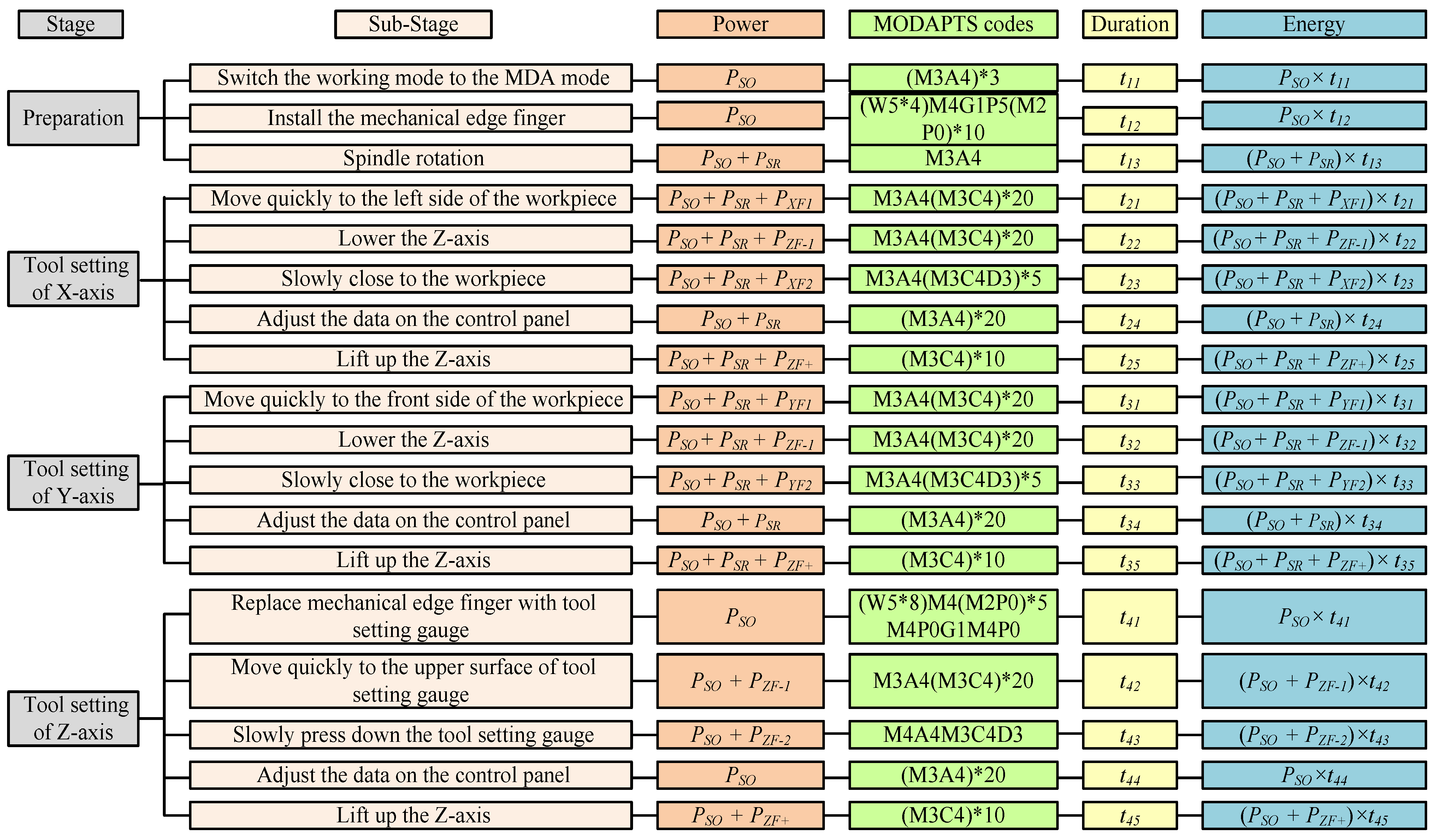
3.1. Operations Decomposition and the MODAPTS Codes Determination for the Tool Setting Process
3.2. Power Modeling of the Basic Action Elements of the Machine Tool
- (1)
- Standby operating power
- (2)
- Spindle rotating power
- (3)
- X-axis feeding power
- (4)
- Y-axis feeding power
- (5)
- Z-axis feeding power
3.3. Energy Consumption Estimation Modeling Based on the MODAPTS for the Tool Setting Process
4. Case Study
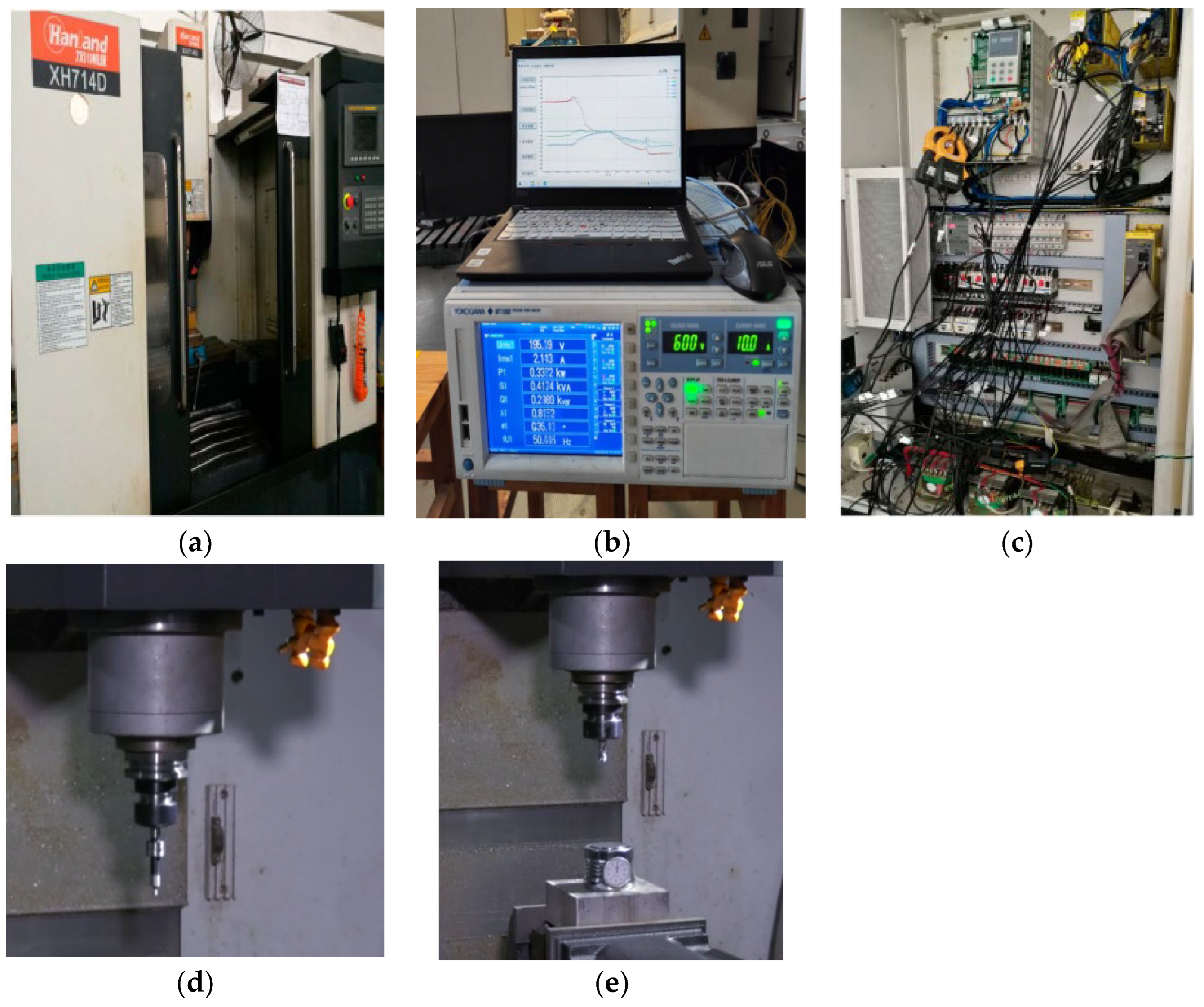
4.1. Experiment Details
4.2. Results
- (1)
- Standby operating power
- (2)
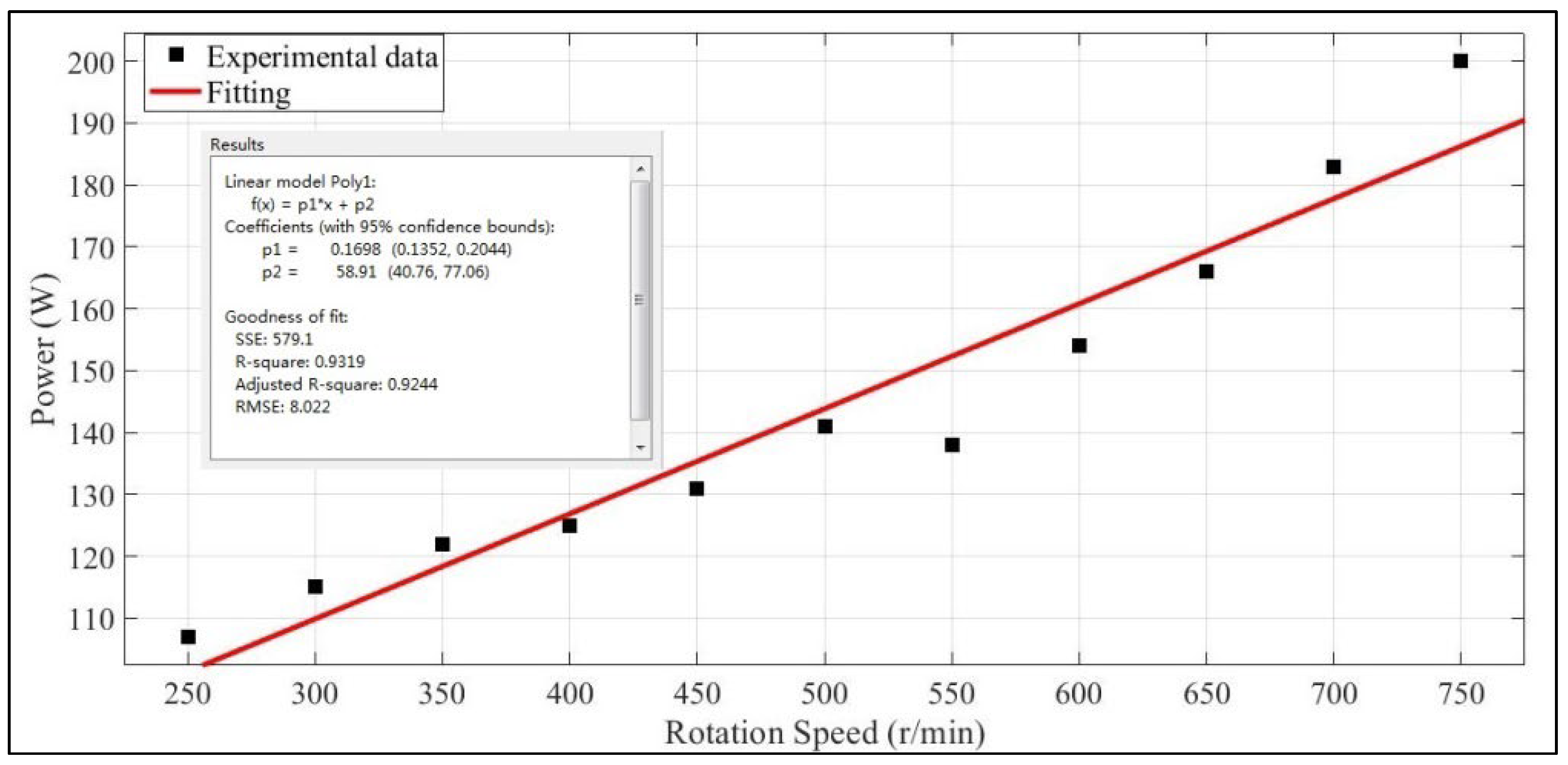
- Spindle rotating power
- (3)
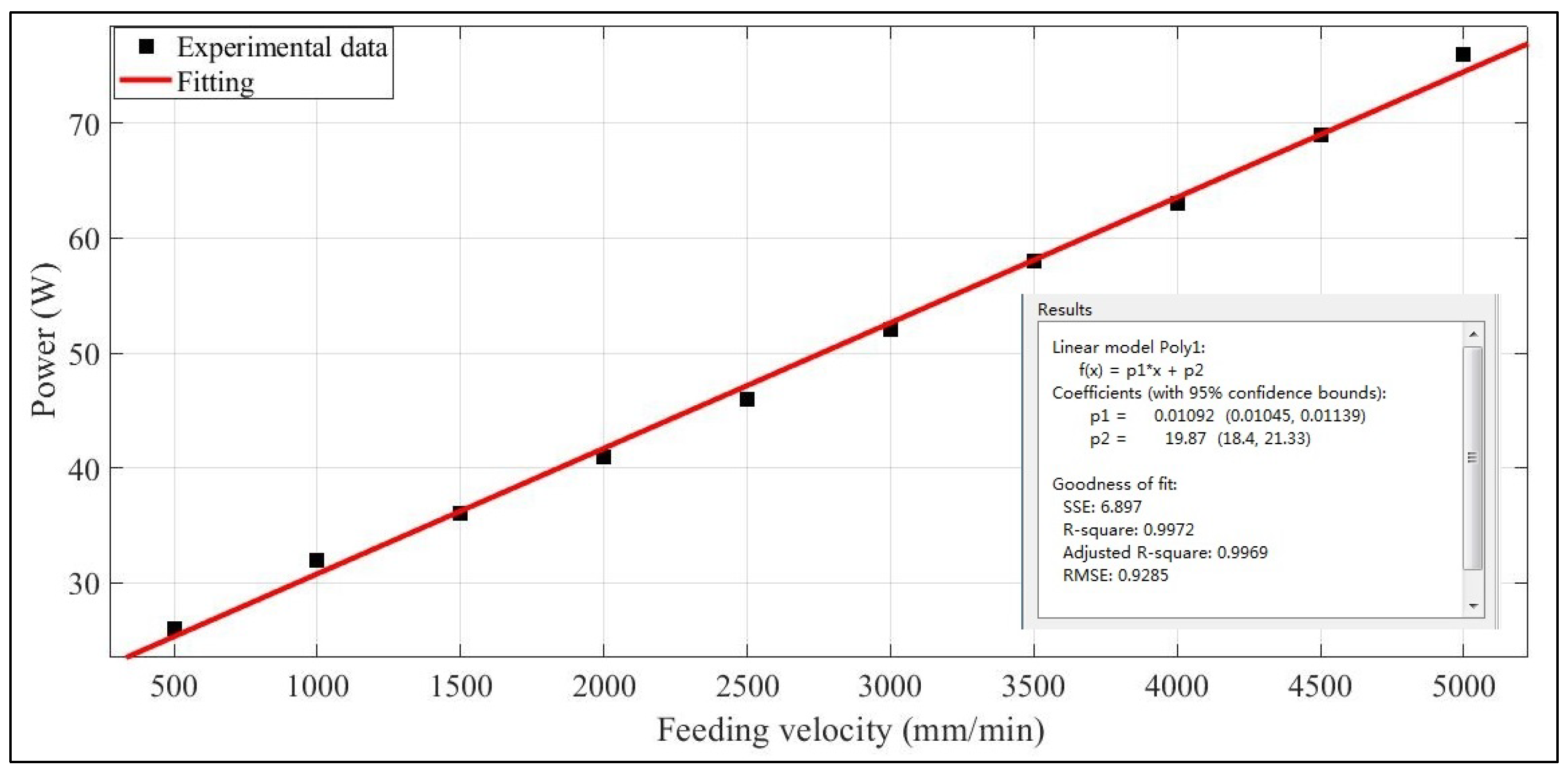
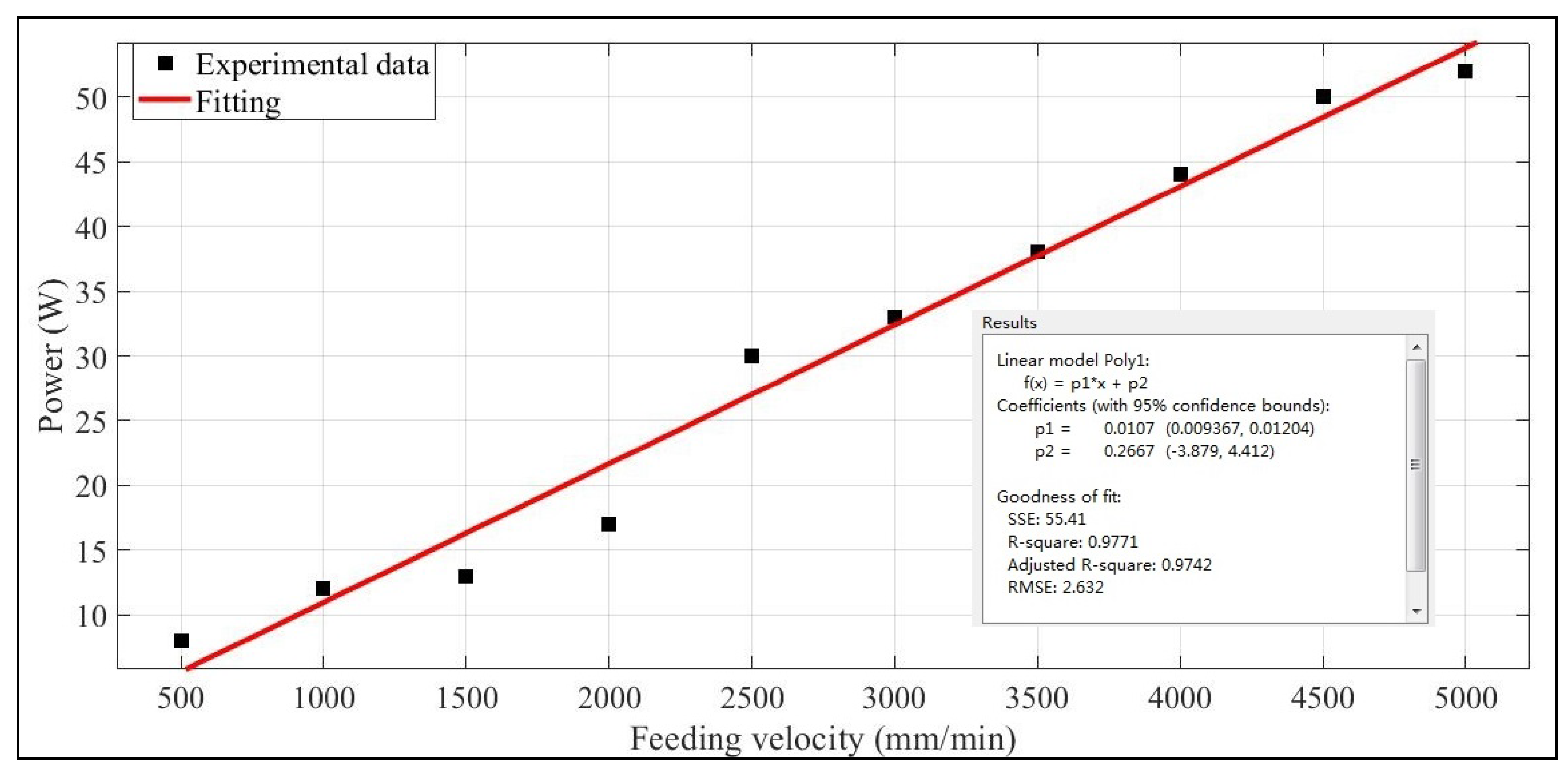
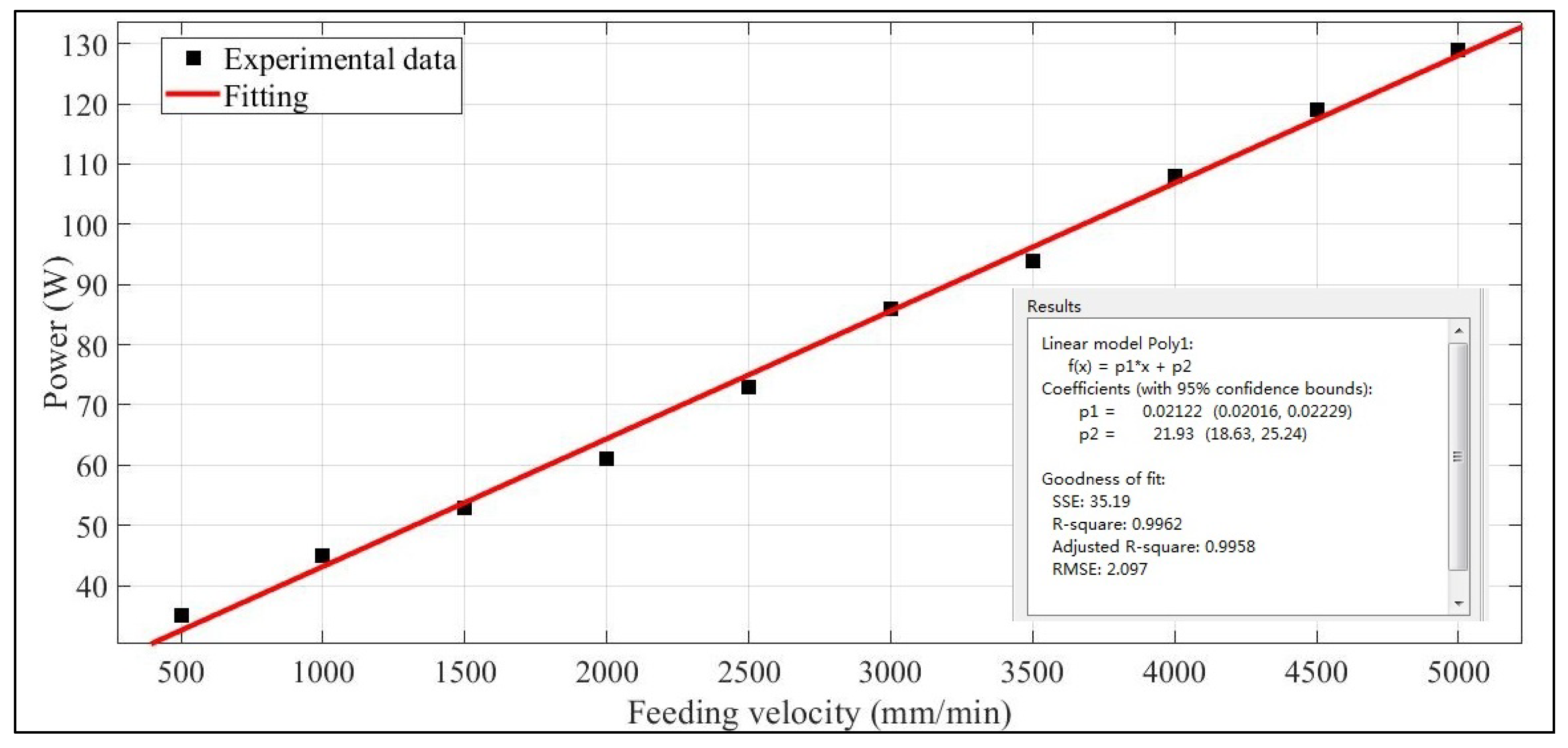
- Feeding power of the X-, Y-, and Z-axes
Energy Consumption Estimation
5. Discussion
6. Conclusions
- The energy consumption of the tool setting process is considered for the first time.
- Human operations in the tool setting process are decomposed into basic actions as defined in the MODAPTS. Based on these, the operating times are determined without any measurements.
- Detailed power models for the machine tool are established from the perspective of the basic action elements.
- The energy consumption estimation model is established based on action decomposing both for the operator and the machine tool.
Author Contributions
Funding
Data Availability Statement
Acknowledgments
Conflicts of Interest
References
- Solnørdal, M.; Foss, L. Closing the energy efficiency gap—A systematic review of empirical articles on drivers to energy efficiency in manufacturing firms. Energies 2018, 11, 518. [Google Scholar] [CrossRef]
- Energy Information Administration (EIA). International Energy Outlook 2017; U.S. Energy Information Administration: Washington, DC, USA, 2017; p. 76. [Google Scholar]
- Wang, J.; Cai, B. Striving for Carbon Dioxide Peaking and Carbon Neutrality. QIU SHI 2022, 3, 43–49. [Google Scholar]
- Salahi, N.; Jafari, M.A. Energy-performance as a driver for optimal production planning. Appl. Energy 2016, 174, 88–100. [Google Scholar] [CrossRef]
- Giampieri, A.; Ling-Chin, J.; Ma, Z.; Smallbone, A.; Roskilly, A. A review of the current automotive manufacturing practice from an energy perspective. Appl. Energy 2020, 261, 114074. [Google Scholar] [CrossRef]
- Li, C.; Liu, F.; Cao, H. Energy Efficiency Theory and Technology of Machining and Manufacturing Systems; China Machine Press: Beijing, China, 2022; p. 5. (In Chinese) [Google Scholar]
- Gutowski, T.G.; Branham, M.S.; Dahmus, J.; Jones, A.J. Thermodynamic Analysis of Resources Used in Manufacturing Processes. Environ. Sci. Technol 2009, 43, 1584–1590. [Google Scholar] [CrossRef]
- Liu, P.; Liu, F.; Qiu, H. A novel approach for acquiring the real-time energy efficiency of machine tools. Energy 2017, 121, 524–532. [Google Scholar] [CrossRef]
- Jia, S.; Yuan, Q.; Lv, J.; Liu, Y. Therblig-embedded value stream mapping method for lean energy machining. Energy 2017, 138, 1081–1098. [Google Scholar] [CrossRef]
- Cai, W.; Wang, L.; Li, L.; Xie, J.; Jia, S.; Zhang, X.; Jiang, Z. A review on methods of energy performance improvement towards sustainable manufacturing from perspectives of energy monitoring, evaluation, optimization and benchmarking. Renew. Sustain. Energy Rev. 2022, 159, 112227. [Google Scholar] [CrossRef]
- Jia, S.; Yuan, Q.; Cai, W. Establishment of an Improved Material-Drilling Power Model to Support Energy Management of Drilling Processes. Energies 2018, 11, 2013. [Google Scholar] [CrossRef]
- Jia, S.; Yuan, Q.; Cai, W.; Lv, J.; Hu, L. Establishing prediction models for feeding power and material drilling power to support sustainable machining. Int. J. Adv. Manuf. Technol. 2019, 100, 2243–2253. [Google Scholar] [CrossRef]
- Mori, M.; Fujishima, Y.; Inamasu, Y.; Oda, Y. A study on energy efficiency improvement for machine tools. CIRP Ann. Manuf. Technol. 2011, 60, 145–148. [Google Scholar] [CrossRef]
- Li, L.; Yan, J.H.; Xing, Z.W. Energy requirements evaluation of milling machines based on thermal equilibrium and empirical modelling. J. Clean. Prod. 2013, 52, 113–121. [Google Scholar] [CrossRef]
- Khan, A.M.; Jamil, M.; Salonitis, K.; Shoaib, S.; Zhao, W.; He, N.; Mia, M.; Zhao, G. Multi-Objective Optimization of Energy Consumption and Surface Quality in Nanofluid SQCL Assisted Face Milling. Energies 2019, 12, 710. [Google Scholar] [CrossRef]
- Yan, W.; Zhang, H.; Jiang, Z.; Hon, K.K.B. A new multi-source and dynamic energy modeling method for machine tools. Int. J. Adv. Manuf. Technol. 2018, 95, 4485–4495. [Google Scholar]
- Hernández, A.E.B.; Tomas, B.; Claes, F. Energy and cost estimation of a feature-based machining operation on HRSA. Procedia CIRP 2017, 61, 511–516. [Google Scholar] [CrossRef]
- Zhou, Y.; Zhang, H.; Yan, W.; Ma, F.; Li, G.; Cheng, W. Energy consumption prediction model of plane grinder processing system based on BP neural network. Int. J. Wirel. Mob. Comput. 2018, 14, 320–327. [Google Scholar] [CrossRef]
- Kahraman, A.; Kantardzic, M.; Kahraman, M.M.; Kotan, M. A data-driven multi-regime approach for predicting energy consumption. Energies 2021, 14, 6763. [Google Scholar] [CrossRef]
- Kim, Y.M.; Shin, S.J.; Cho, H.W. Predictive modeling for machining power based on multi-source transfer learning in metal cutting. Int. J. Precis. Eng. Manuf. Green Technol. 2022, 9, 107–125. [Google Scholar] [CrossRef]
- Qin, J.; Liu, Y.; Grosvenor, R. Multi-source data analytics for AM energy consumption prediction. Adv. Eng. Inform. 2018, 38, 840–850. [Google Scholar] [CrossRef]
- Brillinger, M.; Wuwer, M.; Hadi, M.A.; Haas, F. Energy prediction for CNC machining with machine learning. CIRP J. Manuf. Sci. Technol. 2021, 35, 715–723. [Google Scholar] [CrossRef]
- Balogun, V.A.; Edem, I.F.; Adekunle, A. Specific energy based evaluation of machining efficiency. J. Clean. Prod. 2016, 116, 187–197. [Google Scholar] [CrossRef]
- Cai, W.; Liu, F.; Hu, S. An analytical investigation on energy efficiency of high-speed dry-cutting CNC hobbing machines. Int. J. Sustain. Eng. 2018, 11, 412–419. [Google Scholar] [CrossRef]
- Liu, Z.; Guo, Y. A hybrid approach to integrate machine learning and process mechanics for the prediction of specific cutting energy. CIRP Ann.—Manuf. Technol. 2018, 67, 57–60. [Google Scholar] [CrossRef]
- Heinzel, C.; Kolkwitz, B. The impact of fluid supply on energy efficiency and process performance in grinding. CIRP Ann. Manuf. Technol. 2019, 68, 337–340. [Google Scholar] [CrossRef]
- Ma, F.; Zhang, H.; Gong, Q.; Hon, K.K.B. A novel energy efficiency grade evaluation approach for machining systems based on inherent energy efficiency. Int. J. Prod. Res. 2021, 59, 6022–6033. [Google Scholar] [CrossRef]
- Liu, P.J.; Zhang, Z.; Wang, X.; Li, X.; Wang, X.; Tuo, J. A generalized method for the inherent energy performance modeling of machine tools. J. Manuf. Syst. 2021, 61, 406–422. [Google Scholar] [CrossRef]
- Tuo, J.; Liu, F.; Liu, P.; Zhang, H.; Cai, W. Energy efficiency evaluation for machining systems through virtual part. Energy 2018, 159, 172–183. [Google Scholar] [CrossRef]
- Tuo, J.; Liu, F.; Liu, P. Key performance indicators for assessing inherent energy performance of machine tools in industries. Int. J. Prod. Res. 2019, 57, 1811–1824. [Google Scholar] [CrossRef]
- Hou, B.; Zhang, C.; Yang, S. Computer Vision Tool-Setting System of Numerical Control Machine Tool. Sensors 2020, 20, 5302. [Google Scholar] [CrossRef]
- Zhao, L.; Cheng, J.; Yin, Z.; Yang, H.; Chen, M.; Yuan, X. Research on precision automatic tool setting technology for KDP crystal surface damage mitigation based on machine vision. J. Manuf. Process. 2021, 64, 750–757. [Google Scholar] [CrossRef]
- Zhou, T.; Zhang, Z.; Zhou, J.; Zhao, B. Study of quadrifoliate tool-setting method for diamond milling of microlens array. Precis. Eng. 2023, 83, 170–180. [Google Scholar] [CrossRef]
- Zhou, J.; Zhou, T.; Wang, T.; Ruan, B.; Zhao, W.; Wang, X. Study on the tool setting for microlens array machining via swing cutting. J. Manuf. Process. 2023, 85, 636–644. [Google Scholar] [CrossRef]
- Jana, D.R.; Mandal, T. Mathematical Calculation of Effects on Tool Setting on Tool Cutting Angle. In Proceedings of the International MultiConference of Engineers and Computer Scientists 2008, Hong Kong, China, 19–21 March 2008; pp. 1–3. [Google Scholar]
- Kumari, K.V.S.; Jana, D.R.; Kumar, A. Effects of Tool Setting on Tool Cutting Angle on Turning Operation. ARPN J. Eng. Appl. Sci. 2010, 5, 27–31. [Google Scholar]
- Lee, E.S.; Lee, C.H.; Kim, S.C. Machining Accuracy Improvement by Automatic Tool Setting and On Machine Verification. Key Eng. Mater. 2008, 381, 199–202. [Google Scholar]
- Yu, X.; Zhang, Z.; Tian, X.; Huang, L. Method of calculating Assistant Mechanic Time Based on MOD. Mach. Electron. 2009, 4, 68–70. (In Chinese) [Google Scholar]
- Pang, M.; Wang, Z. Research on Wheel Assembly of Speed Governor Based on Model Method. J. Shijiazhuang Tiedao Univ. 2019, 32, 43–47. (In Chinese) [Google Scholar]
- Chen, J.; Zhou, D.; Kang, L.; Ma, L.; Ge, H. A maintenance time estimation method based on virtual simulation and improved modular arrangement of predetermined time standards. Int. J. Ind. Ergon. 2020, 80, 103042. [Google Scholar] [CrossRef]
- Wu, S.; Wang, Y.; BolaBola, J.Z.; Qin, H.; Ding, W.; Wen, W.; Niu, J. Incorporating motion analysis technology into modular arrangement of predetermined time standard (MODAPTS). Int. J. Ind. Ergon. 2016, 53, 291–298. [Google Scholar] [CrossRef]
- Chan, A.H.S.; Hoffmann, E.R.; Chung, C.M.W. Subjective estimates of times for assembly work. Int. J. Ind. Ergon. 2017, 61, 149–155. [Google Scholar] [CrossRef]
- Cho, H.; Park, J. Motion-based method for estimating time required to attach self-adhesive insulators. Comput. Aided Des. 2014, 56, 68–87. [Google Scholar] [CrossRef]
- Alkan, B.; Vera, D.; Ahmad, M.; Ahmad, B.; Harrison, R. A model for complexity assessment in manual assembly operations through predetermined motion time systems. Procedia CIRP 2016, 44, 429–434. [Google Scholar] [CrossRef]
- Vladimir, P.; Yvan, B. Work-Time Identification and Effort Assessment: Application to Fenestration Industry and Case Study. IFAC PapersOnLine 2018, 51, 569–574. [Google Scholar]
- Jia, S.; Tang, R.; Lv, J. Therblig-based modeling methodology for cutting power and its application in external turning. Comput. Integr. Manuf. Syst. 2013, 19, 1015–1024. (In Chinese) [Google Scholar]
- Feng, Z.; Zhang, H.; Li, W.; Yu, Y.; Guan, Y.; Ding, X. Exergy Loss Assessment Method for CNC Milling System Considering the Energy Consumption of the Operator. Processes 2023, 11, 2702. [Google Scholar] [CrossRef]
- Jia, S.; Yuan, Q.; Ren, D.; Lv, J. Energy Demand Modeling Methodology of Key State Transitions of Turning Processes. Energies 2017, 10, 462. [Google Scholar] [CrossRef]
- Cao, J.; Xia, X.; Wang, L.; Zhang, Z.; Liu, X. A Novel CNC Milling Energy Consumption Prediction Method Based on Program Parsing and Parallel Neural Network. Sustainability 2021, 13, 13918. [Google Scholar] [CrossRef]
- Cai, W.; Liu, F.; Zhou, X.; Xie, J. Fine energy consumption allowance of workpieces in the mechanical manufacturing industry. Energy 2016, 114, 623–633. [Google Scholar] [CrossRef]
- Zhou, X.; Liu, F.; Cai, W. An energy-consumption model for establishing energy-consumption allowance of a workpiece in a machining system. J. Clean. Prod. 2016, 135, 1580–1590. [Google Scholar] [CrossRef]


| Movement Actions | Terminal Actions | Auxiliary Actions | |||||
|---|---|---|---|---|---|---|---|
| Definition | Code | Definition | Code | Definition | Code | Definition | Code |
| Finger movement | M1 | Touch | G0 | Weight factor | L1 | Eye use | E2 |
| Wrist movement | M2 | Grasp easily | G1 | Walk | W5 | Correct | R2 |
| Forearm movement | M3 | Grasp with attention | G3 | Bend and rise | B17 | Judge and react | D3 |
| Whole arm movement | M4 | Place easily | P0 | Stand and sit | S30 | Press | A4 |
| Unbend arm movement | M5 | Place with attention | P2 | Foot acts on the footboard | F3 | Circular movement | C4 |
| Place with assembly | P5 | ||||||
| Substages | Description of Actions | Action Code | Frequency | Substage Code | MODs |
|---|---|---|---|---|---|
| Move quickly to the left side of the workpiece | Press the button | M3A4 | 1 | M3A4(M3C4)*20 | 147 |
| Rotate the handwheel | M3C4 | 20 | |||
| Lower the Z-axis | Press the button | M3A4 | 1 | M3A4(M3C4)*20 | 147 |
| Shake the wheel | M3C4 | 20 | |||
| Slowly close to the workpiece | Press the button to reduce the feeding rate | M3A4 | 1 | M3A4(M3C4D3)*5 | 57 |
| Rotate the handwheel, and judge the position of the edge finger | M3C4D3 | 5 | |||
| Adjust the data on the control panel | Press the button frequently | M3A4 | 20 | (M3A4)*20 | 140 |
| Lift up the Z-axis | Rotate the handwheel | M3C4 | 10 | (M3C4)*10 | 70 |
| No. | Basic Action Elements | Code | Description |
|---|---|---|---|
| 1 | Standby operating | SO | Switch on the main power and keep the electrical control system, the CNC system, lubricating system, etc., running |
| 2 | Spindle rotating | SR | Rotate the spindle at a certain speed without cutting a workpiece |
| 3 | X-axis feeding | XF | Feed in the X-axis of the feeding system at a certain speed without cutting a workpiece |
| 4 | Y-axis feeding | YF | Feed in the Y-axis of the feeding system at a certain speed without cutting a workpiece |
| 5 | Z-axis feeding | ZF | Feed in the Z-axis of the feeding system at a certain speed without cutting a workpiece |
| Items | Spindle Speed Range [r/min] | Spindle Power [KW] | Distance of Travel XYZ [mm] | Maximum Feeding Velocities [mm/min] |
|---|---|---|---|---|
| Values | 60–8000 | 7.5 | 650 × 400 × 500 | 20,000 |
| Items | n [r/min] | vx [mm/min] | vy [mm/min] | vz+ [mm/min] | vz− [mm/min] | |||
|---|---|---|---|---|---|---|---|---|
| vx1 | vx2 | vy1 | vy2 | vz−1 | vz−2 | |||
| Values | 700 | 1500 | 500 | 1500 | 500 | 1500 | 1500 | 500 |
| Items | Values | ||||||||||
|---|---|---|---|---|---|---|---|---|---|---|---|
| Spindle rotation speed [r/min] | 250 | 300 | 350 | 400 | 450 | 500 | 550 | 600 | 650 | 700 | 750 |
| Measured power [W] | 107 | 115 | 122 | 125 | 131 | 141 | 138 | 154 | 166 | 183 | 200 |
| Power Models | R-Square |
|---|---|
| PSO = 530 W | - |
| PSR = 58.909 + 0.1698n | 0.9319 |
| PXF = 19.867 + 0.0109vx | 0.9972 |
| PYF = 0.2667 + 0.0107vy | 0.9771 |
| PZF+ = 21.933 + 0.0212vz+ | 0.9962 |
| PZF- = 2.6667 + 0.0048vz− | 0.9648 |
| Items | Values | ||||||||||
|---|---|---|---|---|---|---|---|---|---|---|---|
| Feeding velocity [mm/min] | 500 | 1000 | 1500 | 2000 | 2500 | 3000 | 3500 | 4000 | 4500 | 5000 | |
| Measured X-axis feeding power [W] | 26 | 32 | 36 | 41 | 46 | 52 | 58 | 63 | 69 | 76 | |
| Measured Y-axis feeding power [W] | 8 | 12 | 13 | 17 | 30 | 33 | 38 | 44 | 50 | 52 | |
| Measured Z-axis feeding power [W] | Z+ | 35 | 45 | 53 | 61 | 73 | 86 | 94 | 108 | 119 | 129 |
| Z− | 6 | 8 | 10 | 13 | 13 | 14 | 20 | 21 | 25 | 28 | |
| Power [W] | PSO | PSR | PXF | PYF | PZF+ | PZF− | |||
|---|---|---|---|---|---|---|---|---|---|
| PXF1 | PXF2 | PYF1 | PYF2 | PZF−1 | PZF−2 | ||||
| Values | 530 | 177.85 | 36.22 | 25.32 | 16.32 | 5.62 | 53.73 | 9.87 | 5.07 |
| Stages | Substages | tij [s] | Pij [W] | TSECij [J] | TSECi [J] |
|---|---|---|---|---|---|
| Stage 1 (preparation) | Substage 1 | (M3A4)*3 = 2.709 | 530 | 1435.77 | 5493.46 |
| Substage 2 | (W5*4)M4G1P5(M2P0)*10 = 6.45 | 530 | 3418.50 | ||
| Substage 3 | M3A4 = 0.903 | 707.85 | 639.19 | ||
| Stage 2 (tool setting of the X-axis) | Substage 1 | M3A4(M3C4)*20 = 18.963 | 744.07 | 14,109.80 | 52,771.76 |
| Substage 2 | M3A4(M3C4)*20 = 18.963 | 717.72 | 13,610.12 | ||
| Substage 3 | M3A4(M3C4D3)*5 = 7.353 | 733.17 | 5391.00 | ||
| Substage 4 | (M3A4)*20 = 18.06 | 707.85 | 12,783.77 | ||
| Substage 5 | (M3C4)*10 = 9.03 | 761.58 | 6877.07 | ||
| Stage 3 (tool setting of the Y-axis) | Substage 1 | M3A4(M3C4)*20 = 18.963 | 724.17 | 13,732.44 | 52,062.38 |
| Substage 2 | M3A4(M3C4)*20 = 18.963 | 707.85 | 13,422.96 | ||
| Substage 3 | M3A4(M3C4D3)*5 = 7.353 | 713.47 | 5246.14 | ||
| Substage 4 | (M3A4)*20 = 18.06 | 707.85 | 12,783.77 | ||
| Substage 5 | (M3C4)*10 = 9.03 | 761.58 | 6877.07 | ||
| Stage 4 (tool setting of the Z-axis) | Substage 1 | (W5*8)M4(M2P0)*5M4P0G1M4P0 = 8.127 | 530 | 4307.31 | 30,354.08 |
| Substage 2 | M3A4(M3C4)*20 = 18.963 | 539.87 | 10,237.55 | ||
| Substage 3 | M4A4M3C4D3 = 1.806 | 535.07 | 966.34 | ||
| Substage 4 | (M3A4)*20 = 18.06 | 530 | 9571.80 | ||
| Substage 5 | (M3C4)*10 = 9.03 | 583.73 | 5271.08 | ||
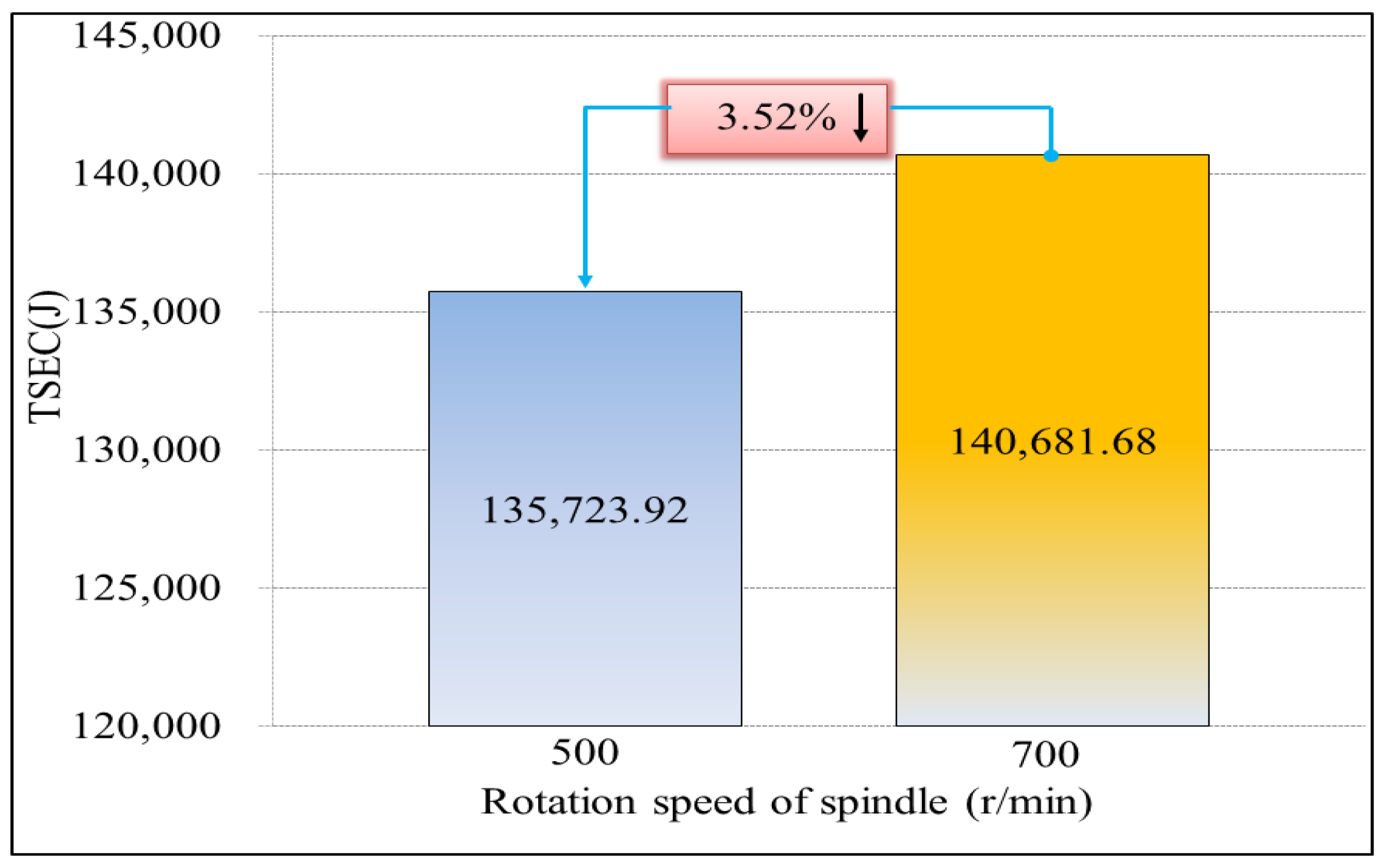
| Total | 210.786 | / | 140,681.68 | 140,681.68 | |
Disclaimer/Publisher’s Note: The statements, opinions and data contained in all publications are solely those of the individual author(s) and contributor(s) and not of MDPI and/or the editor(s). MDPI and/or the editor(s) disclaim responsibility for any injury to people or property resulting from any ideas, methods, instructions or products referred to in the content. |
© 2023 by the authors. Licensee MDPI, Basel, Switzerland. This article is an open access article distributed under the terms and conditions of the Creative Commons Attribution (CC BY) license (https://creativecommons.org/licenses/by/4.0/).
Share and Cite
Feng, Z.; Ding, X.; Zhang, H.; Liu, Y.; Yan, W.; Jiang, X. An Energy Consumption Estimation Method for the Tool Setting Process in CNC Milling Based on the Modular Arrangement of Predetermined Time Standards. Energies 2023, 16, 7064. https://doi.org/10.3390/en16207064
Feng Z, Ding X, Zhang H, Liu Y, Yan W, Jiang X. An Energy Consumption Estimation Method for the Tool Setting Process in CNC Milling Based on the Modular Arrangement of Predetermined Time Standards. Energies. 2023; 16(20):7064. https://doi.org/10.3390/en16207064
Chicago/Turabian StyleFeng, Zhaohui, Xinru Ding, Hua Zhang, Ying Liu, Wei Yan, and Xiaoli Jiang. 2023. "An Energy Consumption Estimation Method for the Tool Setting Process in CNC Milling Based on the Modular Arrangement of Predetermined Time Standards" Energies 16, no. 20: 7064. https://doi.org/10.3390/en16207064
APA StyleFeng, Z., Ding, X., Zhang, H., Liu, Y., Yan, W., & Jiang, X. (2023). An Energy Consumption Estimation Method for the Tool Setting Process in CNC Milling Based on the Modular Arrangement of Predetermined Time Standards. Energies, 16(20), 7064. https://doi.org/10.3390/en16207064