Review

Dual-Motor Dual-Source High Performance EV: A Comprehensive Review

by
Chi T. P. Nguyen
1,2,
Bảo-Huy Nguyễn
3,
Minh C. Ta
1,3 and
João Pedro F. Trovão
1,4,*
1
e-TESC Laboratory, Département de Génie Électrique et de Génie Informatique, Faculté de Génie, University of Sherbrooke, Sherbrooke, QC J1K 2R1, Canada
2
Faculty of Electrical Engineering, Thainguyen University of Technology, Thainguyen 250000, Vietnam
3
CTI Laboratory, Hanoi University of Science and Technology, Hanoi 100000, Vietnam
4
IPC-ISEC and INESC Coimbra, 3030-199 Coimbra, Portugal
*
Author to whom correspondence should be addressed.
Energies 2023, 16(20), 7048; https://doi.org/10.3390/en16207048
Submission received: 1 September 2023 / Revised: 3 October 2023 / Accepted: 5 October 2023 / Published: 11 October 2023
(This article belongs to the Section E: Electric Vehicles)

Abstract

:
Electric vehicles (EVs) have been regarded as one of the promising alternatives to zero-emission transportation. New EV registrations have increased as a result of government policies and consumers’ awareness of climate change. Moreover, EV technology is being improved through ongoing research and development efforts. Among these, a powertrain with a combination of two electric motors has been proposed for high driving and efficiency performance. The study presents a comprehensive state-of-the-art review of architectures and energy distribution for a dual-motor equipped with dual-source EV system. In detail, various dual-motor configurations, and energy management strategies (EMSs) used in the literature are investigated and categorized. A comparison of the benefits and drawbacks of existing topologies and the EMSs of hybrid energy storage systems (HESSs) is also discussed. Following that, research gaps have been considered. This study can be used as a reference for researchers who are interested in the design and optimal control of the dual-motor dual-source EVs.

1. Introduction

Over the last decade, rising pollution levels and the necessity to reduce dependence on fuel have promptly shifted fossil fuel-based vehicles towards vehicles powered by electric motors, known as electric vehicles (EVs). Among EV types, battery EVs (BEVs) are seen as a long-term solution. Without an internal combustion engine, they are completely powered by electricity stored in high-capacity batteries and emit zero emissions. Since the middle of 2010, EV success has been rising quickly. Around 10.5 million new BEVs and plug-in hybrid EVs (PHEVs) were delivered in total in 2022, up +55% from 2021 [1]. By 2050, it is anticipated that EV sales will dominate 10% of the market. Although light-duty vehicles are the initial focus of vehicle electrification, medium- and heavy-duty vehicles are also electrifying at a significant rate thanks to improvements in battery technologies, unique charging infrastructures, and government-supportive policies. According to [2], there were approximately 700,000 medium- and heavy-duty commercial EVs in use worldwide as of the end of 2019.
Based on their powertrain configurations, specifically the number of motors used, EVs can be divided into two main categories: single-motor and multi-motor (dual-motor or four-motor) [3]. In a single-motor EV, both the front and rear wheels are propelled by the same electric motor. This configuration is simpler and more cost-effective. The electric motor is generally good with high efficiency and a wide torque-speed range. Low torque and low speed ranges, though, still exhibit low efficiency. Additionally, its performance is restricted to meet high power demands or difficult driving conditions. Dual-motor EVs with two electric motors are commonly known as an all-wheel drive (AWD). With power delivered to both the front and rear axles, dual-motor powertrains offer better acceleration and improved traction in challenging situations. Furthermore, this powertrain enables the integration of ideal energy management strategies (EMSs), where the operating points of two motors are selected for high efficiency. Each wheel is individually propelled by its own electric motor in a four-motor powertrain. Thus, the highest level of control is available in this configuration, which can achieve exceptional acceleration and handling precision. Nonetheless, design and manufacture are complex and costly. A dual-motor powertrain system is a good balance between performance, cost, and efficiency. It is preferred over single-motor setups for its improved driving and efficiency performance, as well as AWD capability. When compared to four-motor configurations, a dual-motor setup can offer similar benefits while being more practical in terms of price and packaging. Therefore, the dual-motor powertrain is selected in this study.
As previously mentioned, this dual-motor powertrain provides the benefits of a high-performance system. This implies that the energy storage system is under considerable stress. When using only the batteries, high current magnitude/fluctuation tends to accelerate battery degradation. A solution is to combine batteries with supercapacitors (SCs) to create hybrid energy storage systems (HESS). Compared with batteries, SCs are more able to handle high power demands and repeated charging/discharging cycles. As a result, the SCs can protect the batteries from frequent and peak power demands, thereby extending the battery lifetime [4]. Additionally, during acceleration, the vehicle can supply sudden power because of the quick charging and discharging of SCs energy. This leads to a more dynamic driving experience and improved responsiveness.
There are numerous studies reviewing either dual-motor EVs or battery/SCs HESS. For example, a comprehensive review of the dual-motor powertrain for BEVs was carried out by Zhenzhen et al. [3]. This study focuses on describing several coupling configurations, discussing parameter design optimization, and summarizing energy control methodologies. Meanwhile, review articles on HESS are becoming increasingly popular. Ref. [5] provides an overview of the passive and active HESS topologies. Rezaei et al. [6] conducted a survey on the benefits, drawbacks, and trends of EMSs for battery/SCs HESS. Refs. [4,7] evaluated and discussed the structures and EMSs of HESS, integrating batteries and SCs based on a summary and analysis of the previous literature.
Based on the analysis above, we can see that combining a dual-motor powertrain with a dual-source HESS can create a hybrid vehicle with effective driving and efficiency performance across different driving conditions. So far, there has been a lack of review studies involving the system-level design for dual-motor dual-source configurations. According to [8,9], a system design procedure of a dual-motor powertrain with HESS EV includes different levels, as shown in Figure 1.
First, the topologies of dual-motor powertrain and HESS are derived based on the driving EV requirements, priorities, and trade-off between cost and performance. According to a proper topology selection, the optimal parameters of the dual-motor powertrain, including the motor power and gear ratios connected to the motors, are designed. Then, an EMS is applied in accordance with the selected topology and parameter design to minimize an objective function concerning energy loss or power consumption.
This study provides a comprehensive review of each level of the system design framework mentioned in the existing literature. To the best of our knowledge, this is the first review paper to consider the dual-motor powertrain combined with a HESS. The contributions of this paper are as follows: (a) an overview of various topologies involved in dual-motor powertrains and battery/SCs HESSs; (b) insights on parameter design methods in the dual-motor powertrains; (c) a review of the power distribution approaches between two motors and two energy storage systems; and (d) the challenges and research gaps of this system.
The remainder of the study is organized as follows. Section 2 analyzes different topologies composed of a dual-motor powertrain and the battery/SCs HESS, their characteristics, and their applications. Section 3 summarizes the parameter design of the dual-motor powertrain. Section 4 classifies and analysis the advantages and disadvantages of various EMSs applied in dual-motor couplings and battery/SCs HESSs. Section 5 discusses challenges and research gaps. Finally, some conclusions are drawn in Section 6.

2. Configuration

2.1. Dual-Motor Coupling Powertrain

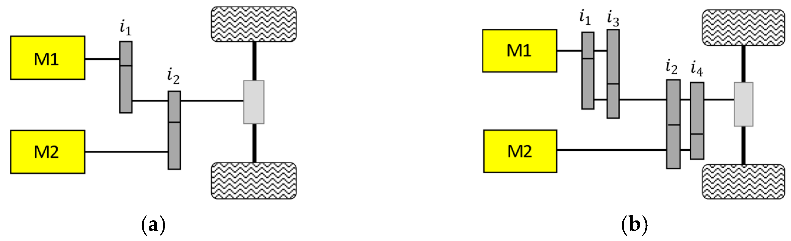
2.1.1. Two Motors Coupled through Gear Pairs

This configuration uses gear pairs to physically connect two electric motors to the drivetrain of the vehicle. The gear pairs act as mechanical links between the motors and the wheels, enabling coordinated power delivery and torque distribution (see Figure 2).
Figure 2a depicts the system configuration of a two-motor, two-speed electric drivetrain [10,11]. Two electric motors are connected to a common shaft through a gear arrangement. The maximum torque of the output shaft is calculated by the sum of the maximum torques of two electric motors (M1 and M2) multiplied by their corresponding gear ratios [12] as follows:
T o u t = T m a x 1 i 1 + T m a x 2 i 2
where T o u t is the output torque; T m a x 1 and T m a x 2 are the maximum torques of M1 and M2, respectively; and i 1 and i 2 are the gear ratios connected to M1 and M2, respectively.
According to (1), two input torques can be changed to produce a specific output torque. For instance, if M1 and M2 are connected to inputs 1 and 2, respectively, and driven wheels are connected to the output, the M1 torque can be used to modify M2 torque while satisfying the required output torque. This enables the M2 to be operated at its optimal torque.
As seen in Figure 2b, a multi-speed gearbox is used to integrate M1 and M2 into the common shaft (presented in [13,14,15,16]). This way, different gear ratios can be selected based on driving conditions and performance requirements. Higher gear ratios maximize top-speed performance, while lower gear ratios provide better acceleration.

2.1.2. Two Motors Coupled via a Planetary Gear

The planetary gear system has three main parts: the sun gear, the ring gear, and the carrier. In general, in this configuration [11,17,18,19],, one motor (e.g., M1) is attached to the sun gear. The other motor (e.g., M2) is coupled to the ring gear. Meanwhile, the output shaft is connected to the planet carrier (Figure 3a).
By controlling the rotation of the different components of the planetary gear system (sun gear, planet carrier, and ring gear), different gear ratios can be achieved. As a result, the output torque and speed can have various values. It should be noted that, to control the operation modes, two wet clutches can be added to the ring gear and sun gear. As a result, three operating modes are available for the system: dual-motor, motor-S only, and motor-R only. When operating in dual-motor mode, both motors are active, and their coupled speed can satisfy the vehicle high-speed requirement [12]:
ω c = ω s 1 + i s r + i s r ω r 1 + i s r
where ω c , ω s , and ω r are the angular velocities of carrier, sun gear and ring gear, respectively; i s r gear ratio that represents the ratio between the tooth number of the sun gear and ring gear.
As seen in (2), the angular velocity of the carrier is equal to the sum of the angular velocities of the sun gear and ring gear. The angular velocity of the ring gear or the sun gear can be changed at a given carrier angular velocity. As M1 is coupled to the ring gear, M2 to the sun gear, and the carrier to the driven wheels, M2 can be sped up or down by M1. This allows M2 to run within its optimal speed range.
Beside the speed coupling, the planetary gear also allows a torque coupling by utilizing a synchronizer (SY) sleeve. As shown in Figure 3b, as presented in [20,21,22], the sun gear is connected to M1. Depending on the position of the SY sleeve, M2 could connect to the sun gear or the ring gear. By engaging and disengaging the clutches and adjusting the SY sleeve position, the dual-motor powertrain can operate in one of four driving modes: single M1 drive, single M2 drive, dual-motor torque coupling drive, or dual-motor speed coupling drive.
As presented in [23,24,25], the planetary gear is recognized in coaxial motor coupling. A two-gear planetary transmission couples the two motors M1 and M2 in a coaxial arrangement. Similarly, the Simpson planetary gear set powertrain is introduced by [26,27,28] and consists of two planetary gearsets (PGS). The sun gears of PGS1 and PGS2 are connected, and the carrier of PGS2 is connected to the ring gear of PGS1. The sun gear of PGS1 is where M1 is connected, and the ring gear of PGS2 is where M2 is connected. These configurations can achieve six different driving modes, including four single-motor driving modes and two dual-motor driving modes.

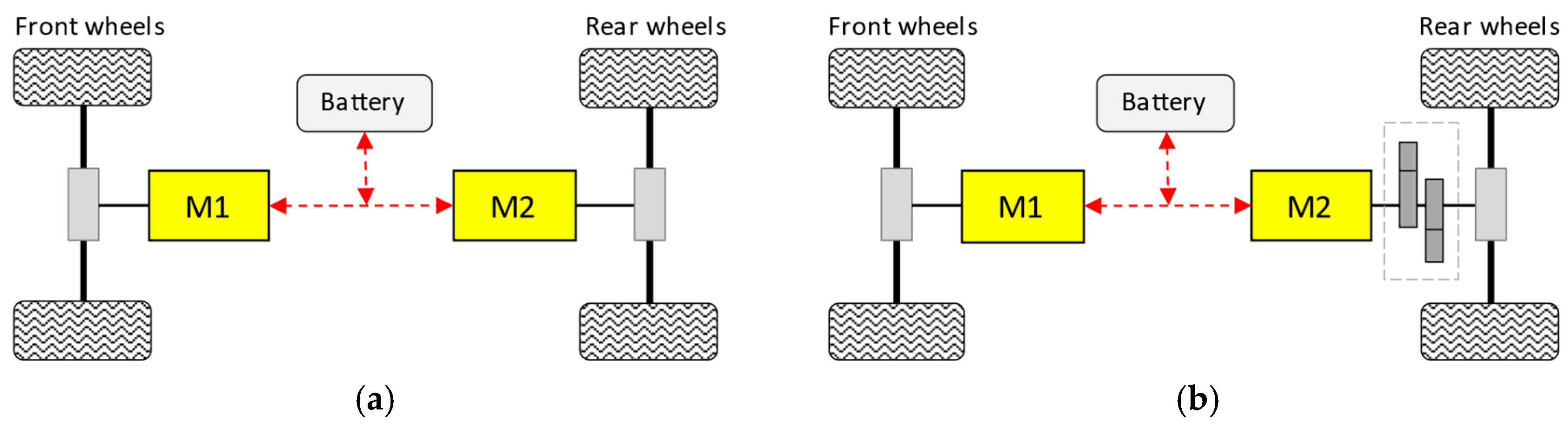
2.1.3. Front-and-Rear Driven Dual Motor Coupling Powertrain

The front-and-rear-drive type in Figure 4 adopts separate motors at the front and rear axles. By having motors at both the front and rear axles, EVs can achieve AWD capabilities. This greatly improves traction and stability, especially in challenging road conditions such as slippery surfaces, uneven terrain, or adverse weather.
Ref. [29] investigates the powertrain system of the dual-motor EV shown in Figure 4a, which consists of an interior permanent magnet (IPM) synchronous machine and an induction machine (IM) located at the front and rear axles, respectively. The power flows in each electric machine are managed by a controller and traction inverter. In [30,31,32], two permanent magnet (PM) motors are connected via a differential to the front and back axles. The dual-motor configuration for an electric bus in [33,34] includes M1 and M2 mounted at the front and rear axles, respectively. In order to detach M2 when the road load is low, a clutch is added between M2 and the rear axle.
The proposed dual-motor 4WD configuration with a two-speed transmission aims to resolve the traditional trade-off between driving performance and efficiency. By leveraging the advantages of dual motors and variable gear ratios, this setup can deliver strong acceleration and traction while optimizing energy consumption during different driving scenarios. The structure of dual-motor and two-speed is shown in Figure 4b. Propelling motors are the front motor (M1) and rear motor (M2). The front motor drives the front wheels through a fixed-ratio reducer, and the rear motor drives the rear wheels via a two-speed transmission [35,36,37].

2.1.4. Comparison

Table 1 provides an overview of the performance of each coupling form in terms of smoothness, structural complexity, coupling effectiveness, control difficulty, cost, and application.
In the first configuration, two motors are directly coupled by a gearset. This is mechanically simpler in design, leading to lower manufacturing and maintenance costs. However, because the available gear ratios are limited, the output speed change is within a narrow range. Thus, the driving requirements may not be satisfied under different conditions. It is noted that while the operating points of two motors can achieve high efficiency at low speed and heavy loads, the energy-saving at high-speed low torque are less clear. Moreover, torque ripples can occur when shifting the individual gears. On the contrary, the planetary gear offers a wide range of gear ratios, allowing for enhanced performance and smoother transitions between gears. Another advantage of the planetary gear-based coupling is advanced torque vectoring, which offers benefits in terms of stability and traction. Nonetheless, this design has limitations due to a complex structural and decreased efficiency caused by mechanical losses. The third configuration, which uses a front-and-rear drive, provides the best stability and traction, even under challenging conditions. Moreover, independent motor control improves system efficiency by maximizing each motor’s efficiency. However, its disadvantages include the mechanical complexity brought on by extra components and the requirement for optimal control methods. From electric sedans to SUVs and trucks, several automakers offer dual-motor EVs suitable for commercial use. The Tesla Model S is one of the first EVs with a dual-motor AWD system [38]. It controls the torque going to the front and back wheels separately and has an IM on the front and a permanent magnet synchronous motor (PMSM) on the rear axles. The time from 0 to 100 km/h is 2.1 s, and the range extends up to 600 km on a single full charge. Similar to the Tesla Model S, the Audi e-tron Quattro is an all-electric SUV with AWD capability [39]. There is a front IM and a rear PMSM. The driving range and acceleration are increased up to 349 miles (worldwide harmonized light-duty vehicles test cycles (WLTC)) and 0–62 mph (0–100 km/h) in 5.4 s, respectively, by adding a new PMSM for the rear axle. According to Nio [40], the ES6 is the first electric SUV with a 210 kW rear IM and a 150 kW front PMSM. The ES6 can reach speeds of 0 to 62 mph in 4.5 s and can travel 510 km on a single charge. The 2022 Jaguar I-Pace electric SUV [41] provides the overall 394 horsepower from its AWD dual motors, one per axle. It can travel up to 292 miles on WLTC and accelerate from 0 to 60 mph in 4.5 s. Rivian introduced the Rivian R1S electric SUV and R1T electric pickup truck in dual-motor versions [42]. The front-and-rear motor powertrain using dual PMSMs produces 533 horsepower, resulting in a predicted 0–60 mph time of 4.5 s for both the R1S and R1T. Two upsized PMSMs, one at each axle of the standard Mustang Mach-E GT [43], provide a combined 480 horsepower, range of 260 miles, and take 3.6 s to reach 60 mph.
Depending on the specific goals, expected performance, and design priorities, the configuration suitable for each research project can be selected. Dual-motor powertrain coupled by a gearset may be appropriate if direct torque coupling and simplicity are priorities. If advanced torque vectoring and efficiency optimization are priorities, front-and-rear drive or planetary gear configurations may be preferable.

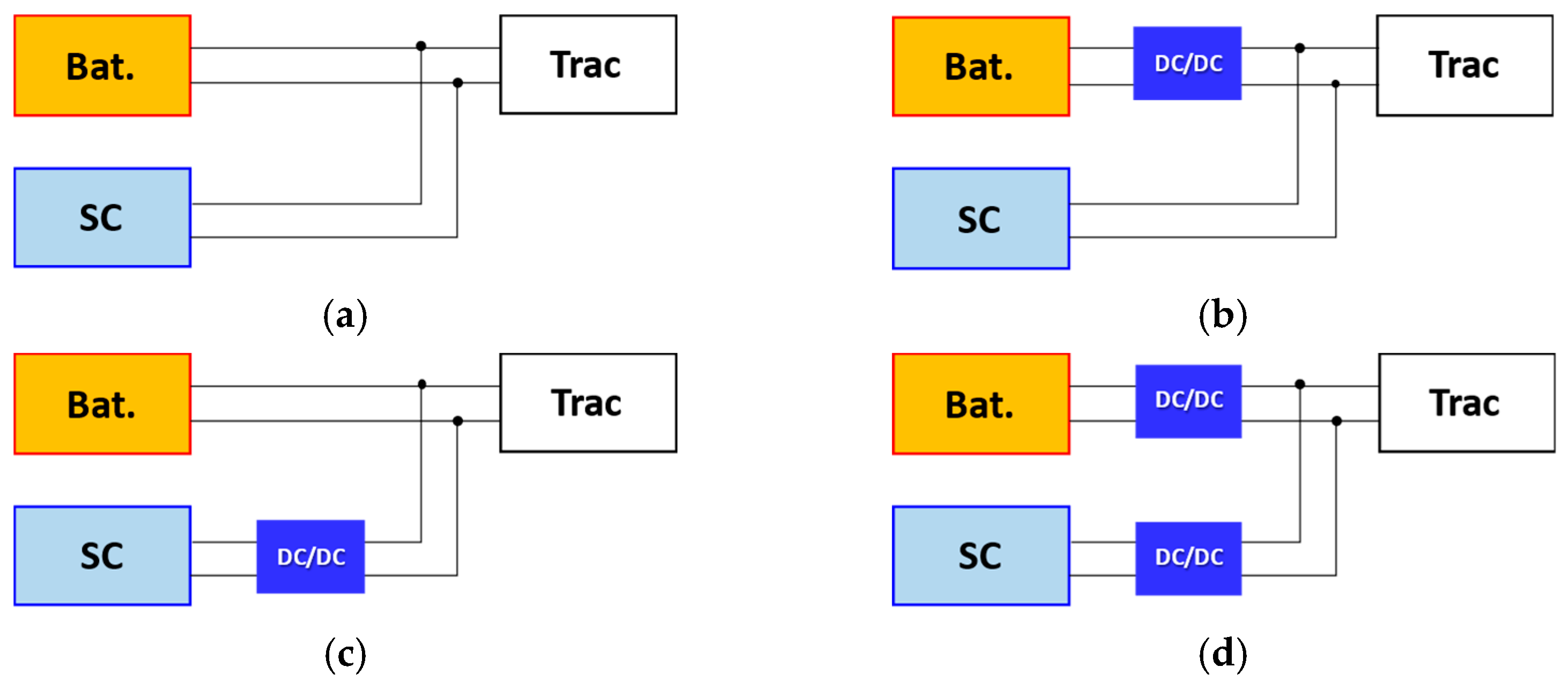
2.2. Battery/SC HESSs

The most widely used energy storage systems (ESSs) are batteries. However, changes in current and cell temperatures have an impact on battery lifespan. Limited power density also results in an increase in size and weight. According to expectations, an ESS for EVs should have a long-life cycle, stable voltage, high energy and power density, quick responses, and quick charging times. It is obvious that a single ESS cannot satisfy all these requirements. Therefore, hybridization high energy-density batteries with high power-density SCs are suggested. SCs are more able to handle high power demands and frequent charging/discharging cycles than the batteries are. As a result, the SCs can protect the batteries from fluctuations and peak power demands, thereby increasing battery lifespan [44]. Regarding battery/SCs HESS topology, there are three major types: passive, semi-active, and fully-active topology, as described in Figure 5 [5].

2.2.1. Passive Topology

Passive topology (Figure 5a) is the simplest hybridization between the batteries and SCs banks and does not require the use of an electronic converter. The voltage of the SCs bank is tied to the battery voltage, which slightly changes during operation. Therefore, passive HESS performance is compromised because SCs cannot be used effectively.

2.2.2. Semi-Active Topology

Among these topologies, semi-active is commonly used. It is a trade-off between passive topology and fully active topology, with medium energy loss, cost, and weight. A DC/DC converter is used to decouple two distinct sources in semi-active HESS. Depending on where the DC/DC converter is connected to SCs or batteries, there are two types: battery semi-active and SC semi-active.
  • Battery semi-active topology
In this topology, as seen in Figure 5b, the SCs are directly connected to the DC bus, while the batteries are separately controlled via a DC/DC converter [45,46,47,48,49,50,51]. Because the nominal voltage of the SCs pack is identical to the bus, many SCs modules in series are required to provide a high bus voltage. The consequence is an increase in SCs volume and cost. In addition, the voltage of SCs cannot change too much because the large corresponding voltage variation of the DC bus can challenge the motor and inverter.
  • SC semi-active topology
As transformed from the battery semi-active topology, the SC semi-active one is obtained by swapping the position of the batteries and SCs pack [52,53,54,55,56,57,58,59,60,61,62]. A DC/DC converter decouples the SCs from the batteries and load. Because the nominal voltage of the battery pack is the same as the nominal bus voltage, the stability of the bus voltage can be maintained. Secondly, the operating voltage of the SCs pack in this topology can vary within a wide range since the DC/DC converter can manage the voltage fluctuation. This also implies that this DC/DC converter is larger than that of the battery/SCs topology.

2.2.3. Fully Active Topology

Using bidirectional DC/DC converters, the fully active topology decouples the batteries and SCs [63,64,65,66,67,68]. One of the benefits of fully active HESSs is that they enable the optimal operation of each energy storage unit, enhancing performance and extending battery life. Nonetheless, this topology demands a larger number of DC/DC converters, which adds more weight, cost, and control complexity.

2.2.4. Comparison

The passive topology has the advantages of simplicity and low cost due to the absence of additional components and its controls. For this reason, it limits the HESS performance to optimize the energy management between batteries and SCs. On the other hand, the fully active topology guarantees the most efficient energy distribution and utilization of SCs for long-term battery protection. This topology requires an increase in cost and control complexity. Semi-active HESS represents a balanced approach between passive and fully active topologies. This compromise can provide improved energy management and efficiency compared to passive systems while avoiding the high complexity and cost of fully active systems. The HESS EMSs can be used for power sharing control between batteries and SCs in both semi-active and fully active topologies.

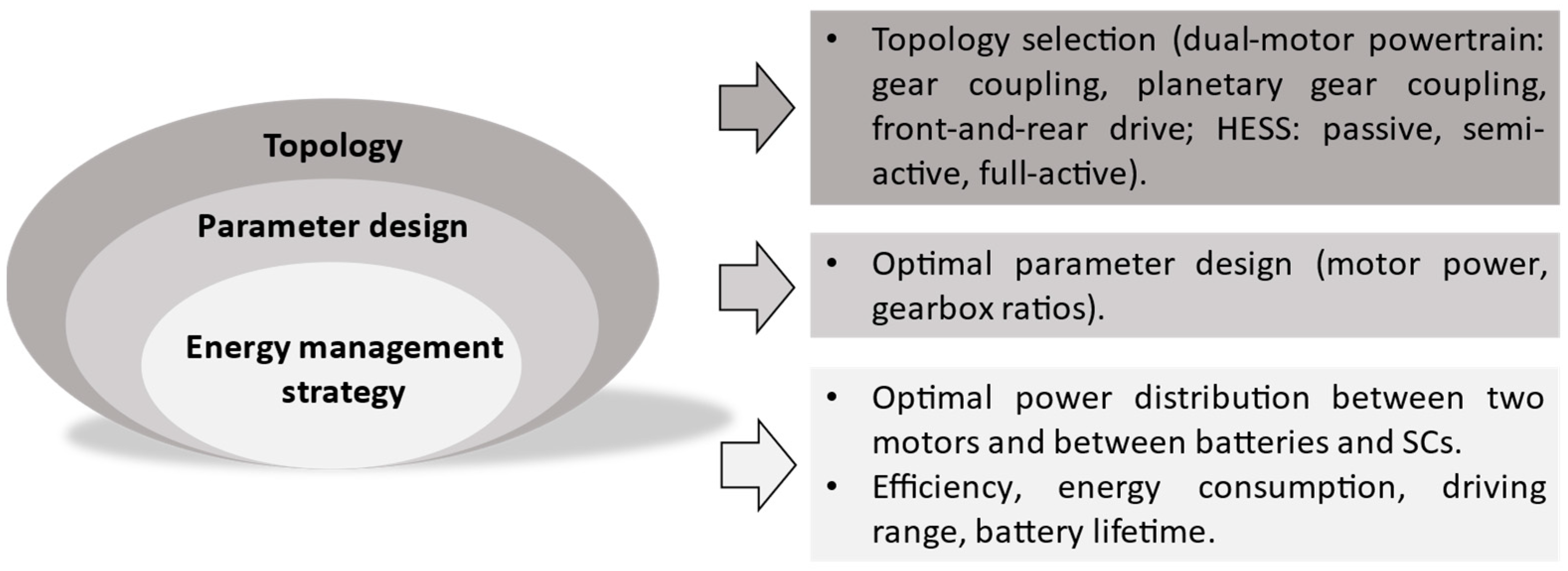
3. Parameter Design of the Dual-Motor Coupling Powertrain

The dual-motor configuration can achieve improved driving and energy performance through motor selection and gearbox ratio design. In other words, the purpose of designing parameters for a dual-motor powertrain system is to deliver superior performance compared to conventional single-motor setups. The design methods in this section can be classified into two groups: empirical- and optimization-based methods. The parameters are determined using an empirical approach based on driving performance metrics like desired acceleration, top speed, and gradeability, whereas an optimization approach can find the best values via cost functions and constraints.

3.1. Empirical-Based Method

With respect to the selected dual-motor coupling configurations, the component parameter design is then carried out using dynamic performance standards (such as top speed, acceleration, and gradeability). For example, the two-speed transmission with rear PMSM is built on the idea of maintaining top speed while offering comparable accelerating and climbing capabilities to the Volkswagen e-Golf, a commercial BEV model [36]. The maximum vehicle speed is used to determine upper limit, while the maximum climbing angle at climbing speed is used to determine the lower limit of the gear ratio. Once the restrictions have been determined, the first gear ratio is set as 11 and the next as 8. For dual-motor propulsion in [11], the gear ratios with planetary transmission and with parallel axle transmission are selected to satisfy the dynamic performance requirements. This vehicle is expected to reach a top speed of 180 km/h, an acceleration time of 10 s (0–100 km/h), and a 40% gradeability. Based on the dynamic constraints, the gear ratios are calculated corresponding to each value of the power distribution ratio. In [69], the gear ratios of the two-speed dual clutch transmission are designed in three aspects, namely top speed, maximum grade, and acceleration time, to meet the vehicle performance requirements. The first gear is chosen for accelerating and climbing; the second gear is used for high-speed cruising. Following several calculations, 2.15 and 1.46 are determined as the first and second gears, respectively.

3.2. Optimization-Based Method

The gear ratios in the dual motor coupling powertrain connected to four speeds are obtained to minimize this function of acceleration time and total electric consumption [13]. It is noted that acceleration performance occurs more frequently than high speed and road grade performance; the acceleration time is considered the objective function. Regarding multi-objective optimization, the non-dominated sorting genetic algorithm II (NSGA-II) principle is employed to reduce computational effort. Compared to the single-motor powertrain, driving ability is improved and the energy consumption is reduced by 5.08%. In [18], a bi-level controller with two optimization loops was developed. By adopting a quadratic Lagrangian nonlinear programming algorithm, the outer loop selects optimal design parameters like gear ratios and the rated power of the ring motor and sun motor. The inner loop then employs the dynamic programming (DP) algorithm to identify the best control approach, where the cost function is the overall energy loss. The simulation results demonstrated that the new design topology can reduce energy loss by 12.4% when compared to the original design. Hong et al. [26] optimized the design variables, which include motor power and gear ratios, of a Simpson planetary gearset-based dual motor powertrain. The optimal objective is to find the minimum required total motor power using a genetic algorithm (GA). In this paper, the dynamic requirements are set as the driving constraints. Also, the GA is employed to find the optimal speed ratios of a two-speed transmission connected to the rear PMSM in [35], aiming at minimizing power consumption. To obtain the optimal parameters of motor scaling powers and gear ratios between the ring gear and sun gear of the Simpson planetary gearset, a neural network fitting (NNF) is proposed in [27] to obtain the continuous Pareto front. In this process, the acceleration ability is considered the dynamic performance indicator (DPI), while the maximum speed and maximum gradeability are used as the dynamic constraints. Tian et al. [23] describe the particle swarm optimization (PSO)-based gear ratio optimization based on both dynamics performance and minimal total power of the two motors. The gear ratio design is optimized using DP for energy consumption minimization [70]. The vehicle dynamic constraints such as the maximum vehicle speed and maximum grade ability are used for two inequality constraints.
Designing the parameters for a proper dual-motor coupling configuration is a crucial step to ensure optimal performance in terms of dynamics and energy consumption. Based on empirical knowledge and experience, the empirical-based method finds gear ratios that align with EV requirements for top speed, acceleration, and gradeability. Meanwhile, the second optimization method formulates the gear ratio selection as an optimization problem, where the objective function combines both dynamics and energy performance metrics. Advanced optimization techniques, such as nonlinear optimization or numerical optimization algorithms, are used. The reviews of parameter design methods for dual-motor powertrains are summarized in Table 2.

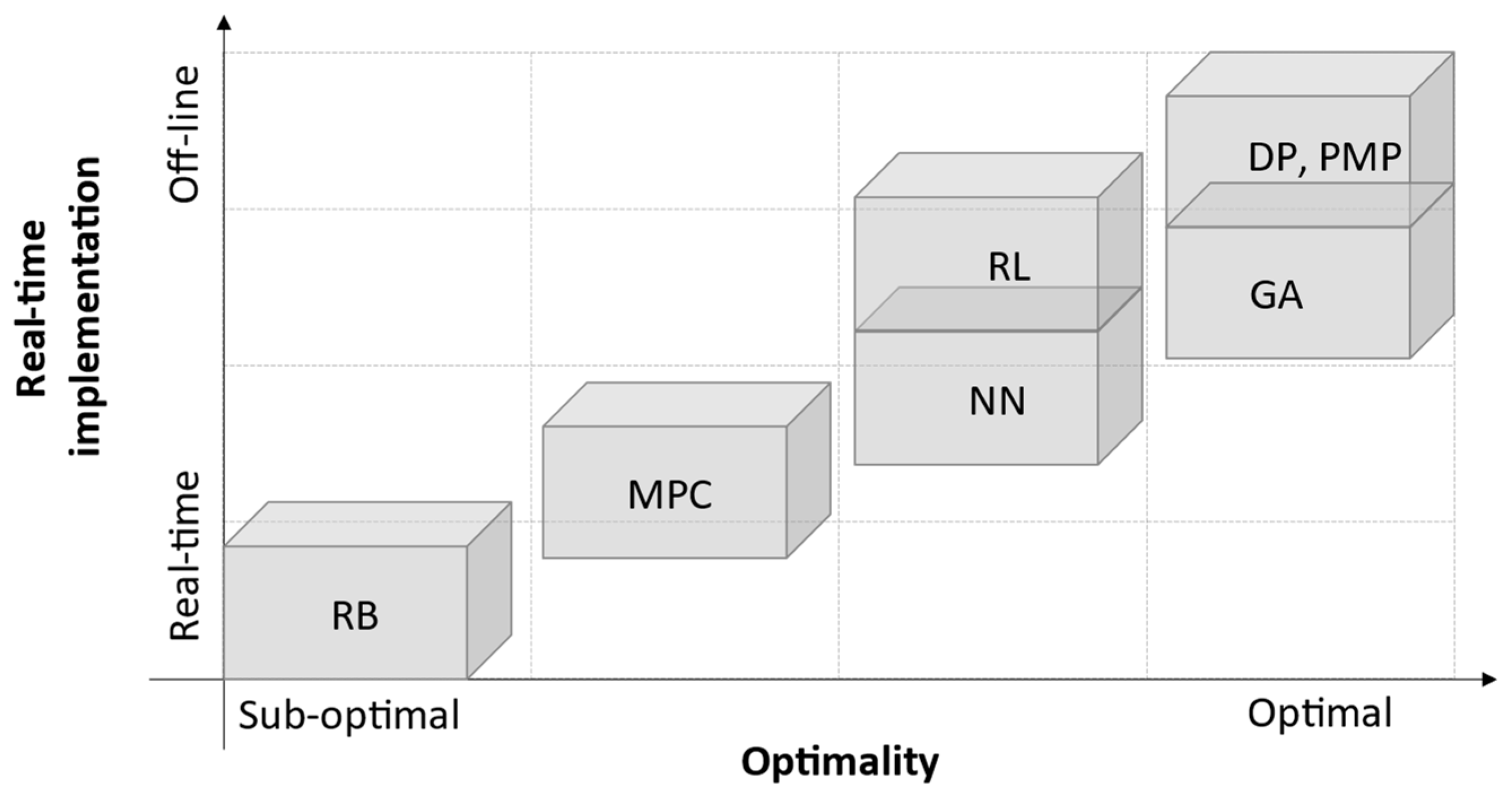
4. Energy Management Strategy

Energy management is a key component of a dual-motor powertrain coupled with a HESS. With more than two power sources, the power flow needs to be controlled to maximize the system performance, overall efficiency, and energy usage. As summarized in Figure 6, a variety of EMSs, including rule-based and optimization-based strategies, have been reviewed in various publications [3,6,7,71].

4.1. Rule-Based Strategy

Rule-based strategy (RBS) is a control strategy that is based on empirical or heuristic knowledge. The approach consists of deterministic rule-based, fuzzy logical, and wavelet transform techniques. It benefits from simple control, robustness, and low computational complexity. Therefore, they are widely used in real-time applications. However, because these rules are pre-defined in accordance with particular cycles, their findings may not guarantee optimum results, and their utilization is limited to various conditions.
By using efficiency maps of electric motors, deterministic minimization, and engineering expertise, a deterministic rule-based strategy is designed for the EMS of dual-motor configurations. Thereafter, if-then rules, look-up tables, and pre-defined maps are generated to determine how much torque or power is shared between two motors.
The papers [21,72] introduce four modes (single motor 1 drive, single motor 2 drive, dual-motor torque coupling drive, and dual-motor speed-coupling drive). Corresponding to each mode, based on analyzing the efficiency of operating points in the motor efficiency map, the power demand is split between two motors by selecting high-efficiency torque-speed pairs. Likewise, by using the motor efficiency map in [32], the torque line configures the power line at the corresponding speed. The power line reveals the power consumption in accordance with the torque distribution ratio of the front and rear wheel motors. The target torques are derived through the lowest power consumption point. By minimizing the total motor demand power, the torque of the second motor is determined in the feasible region [28,32]. Then, using the enumeration algorithm (EA), all possible solutions that satisfy the problem constraints are found. The torque allocation ratio is chosen by a map created offline via EA that corresponds to the values of the pedal position and velocity. To find the approximated global optimum, the enumerating approach is employed as presented in [13,26,73]. Potential solutions to the torque and speed of motor 1 can be explored for the consumed power minimization of two motors. In addition, the limitations of component acceleration and the mechanical power of the planetary gear set are added to the optimization model to avoid the large influence of the gearbox. The increase in energy efficiency as compared to conventional EVs with single-speed transmission is shown over three driving cycles (Louisiana highway 92 (LA 92), new European driving cycle (NEDC), and highway fuel economy cycle (HWFET)). Yuan et al. [30] and Wu et al. [74] found the optimal torque distribution for the total loss minimization of two motors. They consider the total copper loss, iron loss, and friction-bearing loss. As the derivative of P l o s s with respect to T1 is zero, the ideal torque of two motors is half the torque demand, assuming that two motors are identical. According to the experiment results, the equal torque distribution between the two motors illustrates a 4% efficiency improvement under NEDC. The EMS used in the work [37] is based on offline optimization results that minimized the drivetrain power loss, taking into account the power loss contributions from the electric motors, drives, and transmissions. To implement the online EMS, a look-up table obtained by the potential solutions was used. The estimated vehicle speed and total wheel torque demand are the two most important inputs in the look-up tables. As presented in [31], the torque distribution coefficients of the front and rear motors can be adjusted during braking to reduce overall energy loss and improve energy recovery. According to simulation results, this strategy increases the energy recovery over WLTC cycles by 3.35% when compared to the average distribution strategy. Kwon et al. [10] optimized the torque distribution coefficient to reduce the energy consumption of the motors. At each grid point, at specific vehicle speeds and driver commands, the optimization is carried out. As a result, these optimal coefficients during the driving cycles are obtained in a matrix (C). Then, the matrix is applied to the data of the motor model for various gear ratio combinations. Because two motors are identical, they use the same efficiency maps in [11]. The power distribution ratio is heuristically selected at three values as β = 0.5 ;   β = 0.65 ; a n d   β = 0.8 . The comparative simulation results illustrate that the dual-motor with planetary gear transmission and parallel axle transmission has the highest efficiency at β = 0.8 in the three examined cycles of LA92, NEDC, and HWFET. The braking force distribution ratio in [75] between the front and rear motors is presented as a function of the total energy loss. During the braking process, the minimization of the cost function identifies the optimal coefficient values for the specified braking force and initial vehicle speed. When braking conditions (vehicle speeds and demand decelerations) change, a map is plotted that shows the torque distribution ratios at each point on the grid.
On the other hand, the logic threshold strategy and the frequency-based filtering strategy are two common deterministic rules used to distribute power between batteries and SCs. A simple logic threshold is introduced in [51,58,61]. The thresholds of power demand ( P d e m ) and state-of-charge of the SCs ( S o C S C ) are used to define the values of battery power and SCs power. It should be noted that there are two cases where the power of SCs is zero. In driving conditions ( P d e m > 0 ): if S o C S C 0.5 , the SoC of the SCs is at the lower limit and the total power demand is supplied by the batteries only, while the SCs does not output power. Also, if the braking ( P d e m < 0 ), SoC of SCs is at the upper limit as S o C S C 0.9 , then the braking energy is delivered by the batteries to prevent the SCs from overcharging. In addition, the limit voltage of the batteries is considered with the limit voltage of SCs [76]. The rules are defined as follows: if the SoC of the batteries is below 50% and the SoC of the SCs is below 80%, the braking power will charge the SCs. The batteries are plugged in to charge while the vehicle is parked, to up to 90% of its SoC. The articles [49,64] present the general criteria of RBS according to the load power demand. Traction condition ( P d e m 0 ): while P d e m is less or lower than average power ( P a v e ), and SCs do not need to output power. Otherwise, the average power is supplied by the batteries, and the remaining power demand (the rest of the demand power) is supplied by SCs. Braking condition ( P d e m < 0 ): the regenerative braking energy is a priority to charge the SCs because this can reduce the frequent charging current for the batteries.
A frequency-based strategy decouples the demand power into low- and high-frequency components. In HESS, the high-frequency power is provided by SCs, while the low-frequency power is supplied by the batteries. The frequency-based approach can be realized by a simple low-pass filter, or a wavelet transform (WT). Hu et al. [77] incorporated a driving pattern recognition (DPR)-based design into adaptive wavelet transform-based EMSs. Unlike the other studies that adopted a fixed decomposition level, the decomposition levels are identified through DPR, since aggressive patterns are characterized by high power demand and high frequency. Urban, suburban, and highway conditions are represented by levels 2, 3, and 4, respectively. This can restrict battery power within a suitable range and cut down a battery’s current maximum by 58.2%. A real-time power split of HESS is implemented based on wavelet transformation in [52,55]. The power demand is decoupled into high- and low-frequency components by the Harr transformation function with three or five decomposition levels using the urban dynamometer driving schedule (UDDS) cycle. Rule-based EMSs are designed for HESS in [78,79]. The power allocation rules between batteries and SCs are built based on power demand, battery power thresholds, and SC voltages following the general rules in [49,64]. For comparison, a filter is also utilized to separate the power demand into low-frequency (for batteries) and high-frequency (for SCs) components. Based on the results of the simulation, 0.016 Hz is chosen as the cut-off frequency. Two current references of the batteries and SCs are produced as the total load current passes through a low-pass filter. In [66,80], the cut-off frequency was determined adaptively by cutting the frequency spectrum of the load current with the allocation ratio. By using an artificial potential field, the range limit of the SoC of SCs could thus be guaranteed. In [81], an adaptive low pass filter (LPF) structure was developed to realize power coordination between the batteries and SCs. The instantaneous cutoff frequency was self-updated by the length of historic data for each main-loop cycle. A filter-based algorithm was applied in [82] to optimize the energy management between two energy storages. However, the conventional strategy was calculated with a constant cut-off frequency. Hence, an adaptive filtering strategy based on the SCs “ability” was proposed via three driving schemes. Three methods of the rule-based strategy were analyzed and compared in [65], namely LPF, moving average filtering (MAF), and WT. The results of the simulation and experiment demonstrate that the WT has the best power allocation effect, outperforming MAF and LPF.
To implement a fuzzy logic control (FLC), the membership functions of input and output variables are defined in linguistic terms. Then, the if-then rules are established to demonstrate the relationship between the inputs and outputs according to the engineers’ knowledge. The basic components of a FLC include fuzzification, fuzzy rules, an inference engine, and defuzzification; as shown in Figure 7, in the control design process, a precise mathematical model of the objects is not required. In addition, the fuzzy sets and rules can be easily tuned. This provides the FLC with strong adaptability to different conditions and robustness in real-time applications.
Ref. [3] reviews regenerative braking force distribution of a dual-motor configuration. The results demonstrate that the proposed FLC-based EMS cooperating with the driving pattern recognition can improve the braking energy efficiency.
The FLC is employed in [78] to find the sequence of power split ratios between the battery power and SCs power. Three variables, such as SCs voltage ( V S C ), power demand, and C r a t e , are taken as inputs. When V S C and P d e m are high, the relationship between the fuzzy sets and rules reveals that the SCs contribute more energy. Otherwise, the batteries are more active. In order to use effectively the battery energy while respecting the range of SoC of SCs, Trovao et al. [67] investigated a real-time fuzzy rule-based EMS. The SoC of SCs and ratio between the power demand and maximum power of the batteries are two inputs to control the output power of SCs. According to the experiment results, compared to a system using only batteries, the proposed approach reduces the battery current root mean square (RMS) by 12%.

4.2. Optimization-Based Strategy

The optimization-based strategy (OBS) is used to find optimal solutions by minimizing an objective function while respecting the dynamic state constraints. In terms of the dual-motor problem, the power of two motors or the power split ratio can be calculated by minimizing the power consumption or energy cost. In the power management problem of a HESS, the cost functions can be battery energy consumption, the RMS, or the maximum of the battery current. The OBSs can be divided into two categories: offline global optimization and online optimization strategies.

4.2.1. Offline Global Optimization Strategy

Offline strategies are also well-known as global optimization strategies. In this process, prior knowledge of the driving cycle is required in advance. Since their outcomes are determined over a whole cycle for cost function minimization, they can be considered the best possible solutions. Therefore, these strategies are widely used to provide a benchmark in comparison or guide near-optimal solutions in real-time. There are several algorithms adopted in offline optimization.
  • Dynamic programming (DP).
DP is a numerical algorithm that divides the optimal control problem into sub-problems and solves them at each stage [83]. The sub-problem of the last stage is processed first, then the last two stages, etc. The cost function computed in the final stage N is:
J N * x N = min L x N , u N
Then, the optimal cost-to-go function at intermediate stage “k” is calculated backwards based on Bellman’s principle:
J k * x k = m i n u N 1 [ L x k ,   u k + J k + 1 * x k + 1 ]
where L x k , u k is the cost-to-go function from the initial state k t h to the next state k + 1 t h , and J   x k + 1 k + 1 * is the optimum cost function from the state k + 1 t h to the end of the driving cycle.
Figure 8 demonstrates the DP process with two calculation parts. In the backward part, the cost function is minimized, and the optimal control is obtained at the current stage, depending on the cost function optimized in the next stage and the final stage. Meanwhile, the forward calculation determines the optimal functions and optimal control trajectory from the starting to the end stage.
Since a back-step calculation requires the driving information to be known previously, with high computational costs, the DP implementation is not suitable for real-time applications. However, global optimality makes DPs a benchmark to assess other EMSs.
A torque split strategy for a dual-motor coupling system is developed based on DPs, in which the cost function of battery power consumption is determined by the relationship between the state variable (the battery SoC) and the control variable (the torque split ratio) [24,27,84]. Wang et al. [16,85] employ the DP method to calculate the optimal motor torques of coaxial series dual-motor configuration. The objective of the control strategy is to minimize the cost function of battery energy cost under the constraint condition. The DP-based results reduce the energy consumption by 8.8% compared to conventional strategy. To validate the energy-saving performance of proposed EMSs for a dual-motor four-wheel drive, an offline DP is adopted as a benchmark [25,86]. The results obtained by the proposed EMSs can reach more than 90% of the DP performance.
In HESS [87], the power demand is distributed to batteries and SCs by the DP algorithm. A function built to include the cost of batteries, cost of SCs, and cost of DC/DC is selected as the cost function of DP to find the optimal battery power sequence. The authors of [88,89] introduce a battery lifetime model for the HESS. The EMS then adopts DP to obtain the power split ratio between the batteries and SCs. As a result, the battery lifetime and the system cost were significantly improved compared to a rule-based approach.
  • Pontryagin’s Minimum Principle (PMP).
Several global optimization-based EMSs for EVs are designed using the PMP approach. The PMP provides optimal solutions that are close to the DP results with a smaller computation load than DP. The principle of PMP is to find the optimum control solution by minimizing a Hamiltonian function and satisfying the necessary conditions. The Hamilton function is defined by:
H x t , u t , λ t , t = L x t , u t , t + λ t . f ( x t , u t , t )
where x ( t ) is the state variable; u ( t ) control variable; λ ( t ) co-state variable; L ( x ( t ) , u ( t ) , t ) is the cost function; and f ( x ( t ) , u ( t ) , t ) is a state function.
It is noted that the co-state variable λ ( t ) has a significant effect on PMP performance. This variable can be initialized and kept fixed for the sake of simplicity. Alternatively, the PMP calculation is carried out at the initial λ ( t ) value. Then, the co-state is adjusted to increase or decrease within an acceptable range.
The PMP is employed in [19] to identify the optimal control strategy of a dual-motor propulsion system. Through the minimization of the Hamiltonian function and considering the total energy loss, the power split ratio is indicated. In this process, the shooting method is used to realize the initial co-state value.
The aim is to determine the optimal sequence of battery power. Zheng et al. [56] proposed PMP-based EMSs for HESSs to minimize battery lifespan. Therefore, the Hamiltonian is a function of the integrated square of the battery current and the co-state variable. In addition, three necessary conditions are satisfied so that the optimal solution trajectories can be obtained for the entire driving. An alternative approach to PMP (Alt-PMP) was introduced by Nguyen et al. [90]. The Hamiltonian function is reformulated in terms of power and energy. This function is independent of the state variable E s c , thus the co-state variable is a constant value. The battery peak power of the Alt-PMP is found to be a 10.4% reduction compared to DP, while its computation time is 500 times faster.
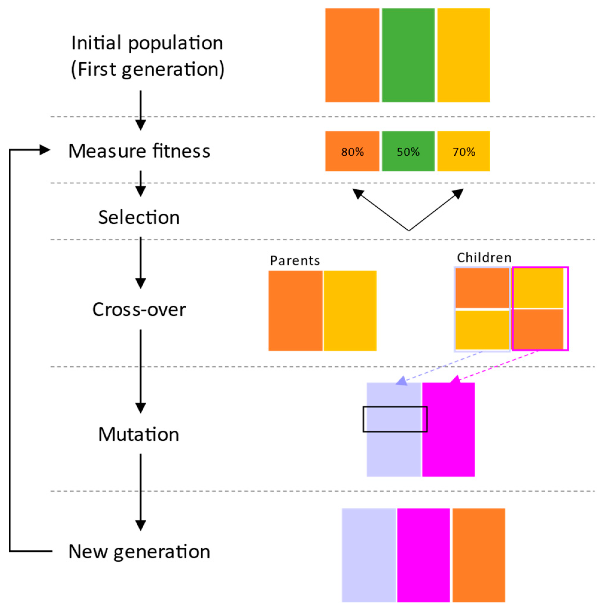
  • Genetic Algorithm (GA).
The GA is an optimization algorithm that is inspired by the evolution process of living organisms to solve complex optimization problems [91]. The GA process is described in Figure 9.
In the first generation, a population is randomly generated S = { s 1 , s 2 ,…, s n }, where n is population size and s represents chromosomes. Different colors of orange, green, and yellow are used to describe these chromosomes as shown in Figure 9. Then, each chromosome in the population S is evaluated based on a fitness function: f 1 , f 2 ,... f n . The chromosomes with higher fitness scores are selected to be parents (the orange and yellow ones). After the parents are selected, their genes are separated and recombined to form new offspring. As the best individuals are selected, new solutions (the blue and purple chromosomes) tend to resemble one another after a few generations. To deal with that problem, a mutation operator is introduced, in which a gene location in a sequence of the blue chromosome is changed. This can help increase the diversity of the population and prevent premature convergence. The process is repeated until the solution with the best fitness is found. In addition, as an extension of the basic GA, the NSGA-II and -III focus on solving multi-objective optimization problems by maintaining non-dominated solutions. This method is commonly used in the parameter design and EMSs of dual-motor configurations and HESSs.
In [14], the torque distribution between motor 1 and motor 2 is adjusted to guarantee optimal energy consumption and shift shock. These two objectives are optimized by the NSGA-II to define the torque distribution coefficient of motor 1. Under different driving cycles, the energy consumption of the proposed strategy differs from that of the benchmark strategy by 2.13%, 11.28%, and 4.73%. Furthermore, the average shift shock is reduced by 5.24%, 12.485%, and 3.52%. By adopting NSGA-II to the dual-motor powertrain in [22], the optimal acceleration is found as a result of a multi-objective function including acceleration duration, energy consumption, and driving comfort. The optimized strategy can save 37.44% of energy consumption.
The authors of [51] discuss the multi-objective optimization strategy for the HESS EV. The optimal distribution of the output powers of batteries and SCs is coupled with the sizing parameters of the HESS components. To solve challenging and multi-objective optimization issues, the GA algorithm is employed.

4.2.2. Online Optimization Strategy

  • Model Predictive Control (MPC).
MPC is introduced to deal with the offline DP optimization since all the information for the entire cycle is known in advance.
As can be seen in to Figure 10, the future output (state variable: x t ) is forecast based on the control law ( u t ) and the predicted model on a future prediction horizon ( N p ). Thereafter, the optimal control law minimizing the cost function over the future control horizon ( N c ). However, the current control law is only imposed on the system. At time t, the control optimizer computes for a relatively short time horizon in the future [ t , t + T ]. Only the first step of control is implemented. Then, the plant is sampled and calculated from the new current state, yielding a new control and a new predicted state. The prediction horizon keeps being shifted forward. The main merit of MPC is its current control law, which considers future predictions. However, MPC optimizes the cost function at each iteration, and the computation increases with a nonlinear predicted model.
An optimal torque allocation problem for front- and rear-axle dual motors is formulated based on the MPC framework [29]. During optimality, energy consumption is minimized based on the inverter loss model. Due to the computational complexity of MPC, PMP is then used to deal with the necessary conditions. Starting with the initial state x ( k ) and the initial co-state λ ( k ) , the co-state is predicted on the N p horizon. If the predicted λ ( k + N p ) satisfies the condition, the optimal control trajectory is obtained.
Chen et al. [45] combined speed prediction and optimal EMS for HESSs. At each time step, the vehicle speed is estimated via the long short-term memory (LSTM) algorithm. The power demand obtained from the speed prediction is used for optimal power allocation from the batteries and the SCs based on MPC. The total energy dissipation of the batteries, the SCs, and the DC/DC converter is selected as the objective function. The SCs voltage is controlled within the voltage range reference. A multi-horizon MPC is proposed in [58] for developing optimal EMS for battery/SC HESSs. The control objective is to find the optimal I S C trajectory so that the battery capacity loss is minimized for a given driving cycle. There are two prediction horizons that are considered. The short horizon is concerned with quick power responses, whereas the long one is concerned with velocity dynamics (acceleration or braking). The multi-objective optimization EMS of the HESS is solved via nonlinear MPC [62]. The goals of the control problem are to lower the battery peak current, reduce the battery current variations, and maintain the SCs voltage near a desired voltage. Additionally, predicting the power demand using an auto-regressive model and a Kalman filter improves MPC performance. Based on a dynamic battery degradation model, the study [78] introduces a novel MPC compared to a rule-based FLC. The power of batteries and SCs is determined via a quadratic solver to minimize the battery current amplitude and variations. In addition, the SCs voltage is controlled to follow the reference. Along with NEDC, the HESS life cost can be reduced by 23% with MPC. However, the MPC is not preferred in practical applications due to heavy calculations. In [92,93], a battery/SCs HESS for an electric bus was designed with a hierarchical EMS. The global DP optimization is implemented in the cloud platform, where the power demand and SoC of SCs are output. The vehicle control unit uses MPC to predict a power split on a predictive horizon based on DP results. The planning of the SoC of SCs and energy losses are included in the cost function of MPC.

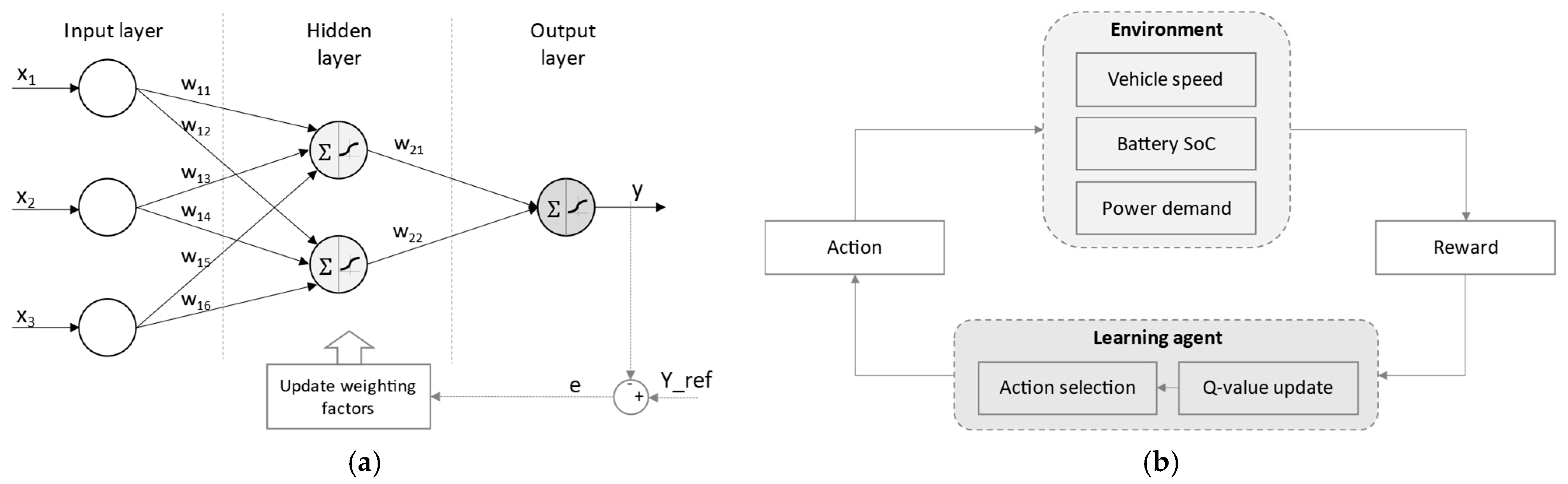
4.2.3. Learning-Based Strategy

Learning-based EMS can be designed to imitate intelligent human behavior through machine learning techniques. These begin with data gathering, which includes various types of information. The learning algorithms are utilized to develop optimal control laws based on this training dataset. After training, the predicted outcome is compared to the target data. If there is a mismatch, the system is retrained multiple times. The rules are adjusted to minimize prediction errors. The retraining process continues until certain predefined criteria are met. To evaluate the generalization capacity to handle the unseen data, the model is tested with a testing dataset. There are several commonly used algorithms, such as reinforcement learning (RL) and neural networks (NNs).
A NN system consists of interconnected nodes, referred to as artificial neurons, and three layers (i.e., input layer, hidden layers, and output layer) (see Figure 11a). Inputs are delivered to each node and multiplied by corresponding weights. The output of the node is then calculated by adding these weighted inputs and then passing through an activation function. During the training process, the weights connecting nodes are adjusted to minimize the difference between the predicted and the reference output [94].
A learning agent interacting with the environment makes up a RL system [95]. As demonstrated in Figure 11b, at each step, the agent receives state information from the environment. Based on the updated Q-value, a new action is created, which is then fed into the environment. As the environment changes to its new state, the agent receives feedback and a reward that has been determined. The agent receives a reward, which is collected as the optimal control policy.
An advanced EMS for dual-motor structures based on delayed deep deterministic policy gradient (TD3) is discussed in [36]. The torque of M1 is chosen as the control action, and the reward is to improve the energy efficiency by controlling the battery SoC consumption. This strategy is accomplished by using a double Q-learning technique, which can prevent Q-value overestimation. According to the simulation results, the energy efficiency of the dual-motor, two-speed powertrain with TD3-based EMS is 6.44% better than that of the single-motor, single-speed powertrain. In [33], a dual-motor EMS based on the deep deterministic policy gradient (DDPG) algorithm is investigated to increase energy efficiency. Maximizing the reward based on SoC consumption yields the optimal torque delivered to the front motor. A novel real-time reward is developed to prevent the effect of coefficient selection on the conventional reward. The torque distribution between dual motors is optimized using the DDPG algorithm [24,86]. After receiving the state observation variables, the action network chooses the appropriate action. Then, the critic network computes a Q value based on the action output of the action network. The loss function of the Q value outputs of the critic network and target critic network is calculated. By minimizing the loss function, the weighting factors in the action network and critic network are updated using the gradient ascent method.
Liu et al. [46] proposes an EMS for the battery/SCs based on a twin-delayed deep deterministic policy gradient algorithm. To reduce training time, the driving condition recognition method is integrated into the EMS framework. The simulation results indicate that the economic difference between the proposed EMS and the DP method is reduced to 3%. The studies [49,50] apply RL to the power management of a battery/SCs HESS. The Q-value is processed while maximizing the reward matrix of the total energy losses in a Markov environment. Compared to the other strategies, the power management strategy based on RL algorithm can save 10% of the energy. As presented in [53,57], firstly, the load demand is effectively distributed between the batteries and SCs by employing DP. This algorithm finds the converter current while minimizing power losses and battery current magnitude variations. Optimal current split sequences are obtained using DP, and then they are used to train a NN. Compared to the batteries-only energy storage system, the proposed energy management controller extends the battery lifetime by 64.8% during the New York driving cycles.

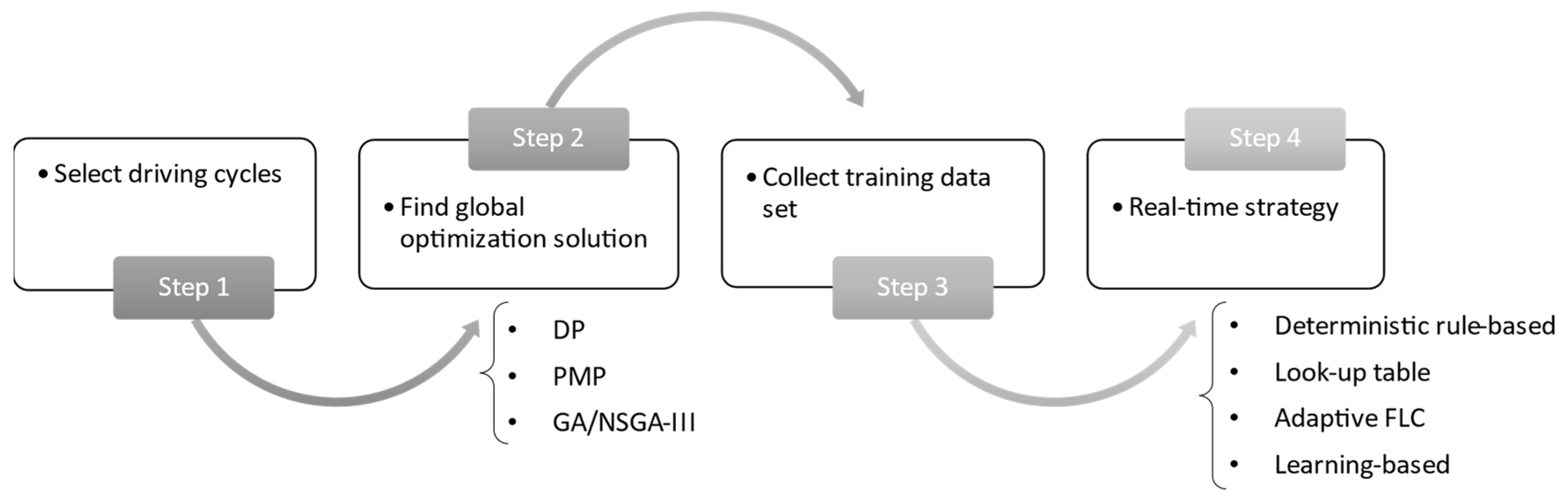
4.2.4. Optimization of Rule-Based Strategy

As mentioned earlier, predefined rules and heuristics are used in rule-based methods, which do not result in the best possible solution. To cope with this restriction, optimization- or learning-based techniques can be employed to optimize control parameters and produce close to optimal outcomes in the EMS [6]. To do so, as shown in Figure 12, the control parameters (such as cut-off frequency, thresholds, and fuzzy parameters) can be modified using optimization techniques like GA and PSO that focus on optimizing a particular objective function. Additionally, control rules based on optimization results can be extracted using learning-based algorithms.
After the vehicle speed is predicted by MPC, the DP algorithm is applied to optimize the power management between two motors with the goal of reducing the total energy loss of dual-motor propulsion system [17]. Next, a NN-based EMS is introduced to avoid the high computational burden in the DP optimization process. Based on the outcomes of the DP calculation during three driving cycles, the training dataset is provided to NN. Ref. [84] introduces a rule-based technique with a stratify-classify-cluster process to efficiently extract the overlapping working points of DP under various conditions. To cluster data, the self-organizing feature map (SOM) and recursive k-means method are used. The optimal shift rules are successfully identified under various driving conditions. The HIL experiment results show that compared to the initial strategy, the blended optimal strategy reduced energy consumption by 29.02%. In [96], analyzing the DP results can help to improve power split control between the main motor and auxiliary motor of the preliminary rule-based algorithm. The split ratio tends to fluctuate around 0.77 when the speed is greater than 20 km/h, as can be seen from the new power split curve. Energy loss can be reduced by the DP by 36.9%, while it can be reduced by the improved rule-based control strategy by about 22%.
The article [68] proposes an LPF-based EMS that considers DPR. The real-time driving patterns are predicted using a supervised learning NN. Then, the PSO algorithm optimizes the cut-off frequency of the filter for each driving pattern to reduce the overall cost, including battery degradation and energy. According to the DPR, DP-based EMS is adopted for the battery/SCs HESS [97], in which the energy loss and the battery usage range are formulated for a cost function. In the DP results analysis, the power split rules are extracted for different driving cycles related to DPR, SoC, power demand, and temperature. The simulation results indicate that the proposed new control rule based on DP optimization improves the system efficiency by 10% compared with the original rule-based system. In [63], the NSGA-III is expected to update offline the FLC parameters while minimizing energy consumption and battery current fluctuation, subjected to constraints on the SoC of the supercapacitor. The fine-tune FLC is used to distribute power to the batteries during the online control phase. According to the experimental results, the optimal fuzzy EMS has good adaptive power distribution capability under different driving conditions. In order to optimize the fuzzy membership functions, Wang et al. [47] employed GA for the energy loss minimization of the HESS as an objective. According to the results, the GA-optimized strategy performs better than the non-optimization strategy. The GA-optimized FLC-based EMS is also validated at various environmental temperatures. The DP approach is used in [54] to optimally distribute the total power to the battery pack and SCs pack. The DP determines the optimal SCs power according to each value of power demand based on operating cost minimization. Then, the threshold for battery–SCs power splitting is predicted by the NN, while the rule-based strategy attempts to mimic the DP solutions. An adaptive EMS with low computational cost targeting hybrid battery/SCs HESS is presented by [98]. Driving patterns are classified throughout the offline training phase using the K-means clustering approach. According to each pattern, control rules are extracted based on the guidance of DP solutions for the online phase. Near-optimal rules are extracted from the DP results by [48,99,100,101] under different battery SoHs. By analyzing the optimization findings, the ideal trajectory for charging/discharging the battery pack and the SCs pack is to consider the battery degradation cost and electricity cost. Finally, the proposed control strategy can reduce total energy loss under different driving types compared to the original strategy.

4.2.5. Other Strategies

In this paper [34], an approach based on convex programming is developed for a dual-motor-driven electric bus powertrain. According to comparative results, this strategy has been demonstrated to maximize electrical efficiency through effective power flow management. Ergodic optimization is used for optimal EMS for a dual-motor two-speed transmission to determine the torque distribution of the front and rear axle motors considering switching gears [35]. Through globally traversing optimization, two sets of torque distribution coefficients are obtained that minimize the power consumption of the motors, corresponding to two transmission gears. The results demonstrate that the proposed strategy can reduce vehicle energy consumption by 9.13% and 11.4%, respectively, in WLTC and UDDS, in comparison to fixed torque distribution. The power distribution strategy of a novel dual-motor coupling–propulsion powertrain system is based on mode division [72,74]. The system efficiency maps, and mode distribution are obtained after calculating the motor power model in various driving modes. These efficiency maps are projected onto the coordinate plane of speed acceleration. For a specific point on the speed–acceleration plane, the optimal driving mode is chosen to maximize system efficiency. The authors of [102] developed a sliding mode control method for controlling the wheel slip ratio, which is the basis for the power distribution between the front and rear motors. Simulations on low friction coefficient roads confirm the effectiveness of the proposed control strategy. The driving torque of the front and rear motors can be independently controlled [103]. The goal is to maximize overall motor efficiency. The objective function is solved using four nonlinear constraint optimization algorithms. It is concluded that PSO is likely to enter the local optimal solution. Adaptive GA improves the global optimal solution by increasing the crossover probability and mutation probability when the optimal solution tends to the local optimal solution, in comparison to PSO. As a result, under most simulation scenarios, adaptive GA performs better overall. However, it takes the longest computational time because the entire population moves to the optimal region. The computational process of the quasi-Newtonian Lagrangian multiplier method and sequential quadratic programming is faster. An optimization function with two objectives is developed for enhancing the dynamic performance and energy consumption of a dual-motor drive system [104]. The quantum genetic intelligence algorithm that combines the quantum algorithm and GA is used for convergence-guaranteed optimization calculations. To increase the overall operating efficiency of two motors, a three-layer EMS consisting of demanded torque calculation, mode decision, and torque split is developed in [105]. The optimal torque allocation using an adaptive nonlinear PSO is embedded in the torque split layer.
For the EMS of HESS, Trovao et al. [106] also used the simulated annealing approach to optimize the energy distribution between the batteries and SCs for short-term EMS (tactical level), while the RB was adopted for long-term EMS (strategic level). The battery/SCs power distribution problem with constrained nonlinearity was successfully solved using a pseudo-spectral approach in [107,108]. Because HESS efficiency is primarily focused on, the optimal control problem considers the minimum HESS energy loss an objective function. The performance of the pseudo-spectral method is found to be superior to the logic threshold control strategy through comparisons. Sliding mode control principles are introduced by Ayad et al. [109] to create a robustness control strategy for the two hybrid sources using SCs and fuel cells, with and without batteries. Multiple variables, including the load current, SCs voltage and current, and DC link voltage and current, are defined on the sliding surface.
In brief, RBS succeeds in real-time implementation due to its simplicity and efficiency. However, RBS can lead to sub-optimal solutions, particularly when there is no integration of constraints. It lacks adaptability to changing conditions or unexpected situations as it relies on predefined rules. Also, calibrating rules and parameters in RBS can be complicated. By contrast, the offline OBS involves heavy computational processing, making it a challenge for online applications. Nonetheless, global optimization approaches aim to find the optimal solution by considering the entire search space and constraints. The MPC is a widely used real-time control strategy known for its effectiveness in handling complex dynamics and constraints in various applications. However, in principle, control decisions are obtained by directly solving an optimization problem in real-time. The complex computations challenge the hardware processor. Besides, the important role of the learning-based EMSs cannot be denied. Their strong learning ability and adaptability to changing conditions have shown exceptional performance in optimizing energy usage and making real-time decisions. However, their effectiveness is often tied to the availability of training data and the complexity of their learning structures. A comparison in terms of the advantages and disadvantages of the main reviewed EMSs is summarized in Table 3.

5. Challenges and Research Gaps

The dual-motor coupling powertrain has demonstrated significant promise in enhancing EV performance, efficiency, and driving experience. However, there are still challenges and gaps that the dual-motor powertrain is facing:

5.1. The Selection of Dual-Motor Coupling Configuration

Choosing between direct gear coupling, planetary gear coupling, or a front-and-rear-driven dual-motor setup may lead to a challenge. It involves trade-offs based on driving performance, efficiency, and complexity. A planetary gear coupling may be appropriate if simplicity is not a concern and high torque, and flexible speed control are required. A direct-gear coupling might be preferred if simplicity is the top priority. If individual control over each motor is important, the front-and-rear-driven dual-motor configuration should be selected. In addition, selecting the appropriate electric motors for a dual-motor coupling configuration EV is an important decision that directly affects the EV performance and efficiency. There are a variety of electric motors available on the market, each with their own advantages and disadvantages. It is possible to use two identical motors for simplicity of control and management since both motors share the same characteristics. Moreover, combining different motors with complementary characteristics can optimize overall efficiency and power delivery across a wider range of operating conditions. An analysis needs to be performed to determine whether selected electric motors are compatible with the specific objectives of the EV design.

5.2. Parameter Design Optimization

According to the configuration, the parameters are designed based on the driving performance requirements. Eventually, the parameter design aims to enhance both driving and economic performance. Hence, a combination of parameter design and EMS still challenges the engineers. In addition, in the parameter design process, the power envelope of motors has not been considered. A power envelope outlines the power requirements of the EV. This envelope indicates the maximum power needed for acceleration, cruise speed, and other driving conditions. The parameters involved in the power envelope determine torque-speed characteristics, maximum power outputs, and efficiency profiles for each motor. This can ensure that these parameters align with the power envelope’s requirements and efficiency improvements.

5.3. Optimal Real-Time EMS

According to the EMSs described in the Section 4, an exploitable gap is identified between the optimization capabilities and real-time implementation, as seen in Figure 13. RB-based strategy is an ideal method for real-time application, but it suffers from suboptimal solutions. Meanwhile, optimization-based strategy provides an optimal solution, but it carries a heavy computational burden. None of these can solely mitigate all requirements. Therefore, different approaches are mixed to improve EMS performance. This combination allows the building of rules based on the global optimization results. Still, there is a large amount of room to develop an optimal real-time approach.

5.4. Dual-Motor Powertrain Equipped with Battery/SC HESS for Off-Road EVs

Since torque distribution between the two motors can be managed in dual-motor systems, this configuration enables improved traction on challenging terrains such as mud, sand, and rocks. Furthermore, two motors have the potential to produce more torque, allowing vehicles to handle off-road conditions well. In fact, the intense acceleration and deceleration of an off-road EV can lead to high power demands and fluctuations. By integrating a HESS in the dual-motor configuration, SCs absorb power spikes and fluctuations, which can extend the battery’s lifespan. Also, due to the handling of rapid power fluctuations in SCs, the power demand must respond quickly, boosting acceleration. In brief, off-road EVs with dual-motor coupling and battery/SCs HESS are a relatively novel idea that could lead to significant improvements in off-road performance.

5.5. Multi-Agent System

A dual-motor powertrain coupled with HESS can be considered a multi-agent system (Figure 14) that consists of multiple individual agents, such as electric motors, batteries, supercapacitors, control units, and the environment, such as road conditions, temperature, and driver behavior. Agents gather data from the environment and communicate with each other to achieve certain goals. This multi-agent system, therefore, optimizes energy management, enhances vehicle performance, and ensures efficient operation in various driving conditions. Appropriate algorithms are employed to set rules that guide the agents’ actions to achieve optimal performance.
On the other hand, considering a dual-motor powertrain coupled with a HESS as a multi-agent system can bring complexity and challenges. The optimization problem is solved with various objectives such as performance, efficiency, emissions, and constraints. Also, it is not easy for agents to learn and adapt in real-time based on changing conditions. Future research should focus on an optimization algorithm design that can handle multiple objectives and adapt to changing priorities.

6. Conclusions

Researchers are increasingly drawn to the design of powertrains and EMSs for dual-motor EVs, as indicated by the growing body of literature on the subject. A proper topology corresponding to optimal EMSs can improve drivability and energy consumption. This paper presents a comprehensive review involved in dual-motor configurations, focusing on three aspects: topology selection, parameter optimization, and EMS. In addition, topologies, and the EMSs for the battery/SCs HESS are considered. Classification, comparison, advantages, and drawbacks of different configurations and EMSs are thus provided. Based on this analysis, research gaps are identified, drawing on advanced techniques for future studies.

Author Contributions

Conceptualization C.T.P.N. and J.P.F.T.; writing—original draft preparation, C.T.P.N.; writing—review and editing, B.-H.N., J.P.F.T. and M.C.T.; supervision, J.P.F.T.; project administration, J.P.F.T. All authors have read and agreed to the published version of the manuscript.

Funding

This work was supported in part by grant 950-230672 of the Canada Research Chairs Program and also in part by the FCT—Portuguese Foundation for Science and Technology project UIDB/00308/2020.

Data Availability Statement

The bibliographic data associated with this paper are available online, in bib, ris, and xml formats. The three corresponding files can be downloaded from the following link: https://github.com/PhuongChi91/DMDSHP_EV_Review, (accessed on 2 October 2023).

Conflicts of Interest

The authors declare no conflict of interest.

References

  1. EV Volumes. 2022. Available online: https://www.ev-volumes.com/ (accessed on 10 September 2023).
  2. IEA. 2020. Available online: https://www.iea.org/reports/global-ev-outlook-2020 (accessed on 10 September 2023).
  3. Wang, Z.; Zhou, J.; Rizzoni, G. A review of architectures and control strategies of dual-motor coupling powertrain systems for battery electric vehicles. Renew. Sustain. Energy Rev. 2022, 162, 112455. [Google Scholar] [CrossRef]
  4. Kouchachvili, L.; Yaïci, W.; Entchev, E. Hybrid battery/supercapacitor energy storage system for the electric vehicles. J. Power Sources 2018, 374, 237–248. [Google Scholar] [CrossRef]
  5. Zimmermann, T.; Keil, P.; Hofmann, M.; Horsche, M.F.; Pichlmaier, S.; Jossen, A. Review of system topologies for hybrid electrical energy storage systems. J. Energy Storage 2016, 8, 78–90. [Google Scholar] [CrossRef]
  6. Rezaei, H.; Abdollahi, S.E.; Abdollahi, S.; Filizadeh, S. Energy managment strategies of battery-ultracapacitor hybrid storage systems for electric vehicles: Review, challenges, and future trends. J. Energy Storage 2022, 53, 105045. [Google Scholar] [CrossRef]
  7. Xiong, R.; Chen, H.; Wang, C.; Sun, F. Towards a smarter hybrid energy storage system based on battery and ultracapacitor—A critical review on topology and energy management. J. Clean. Prod. 2018, 202, 1228–1240. [Google Scholar] [CrossRef]
  8. Tran, D.D.; Vafaeipour, M.; El Baghdadi, M.; Barrero, R.; Van Mierlo, J.; Hegazy, O. Thorough state-of-the-art analysis of electric and hybrid vehicle powertrains: Topologies and integrated energy management strategies. Renew. Sustain. Energy Rev. 2020, 119, 109596. [Google Scholar] [CrossRef]
  9. Silvas, E.; Hofman, T.; Murgovski, N.; Etman, L.P.; Steinbuch, M. Review of Optimization Strategies for System-Level Design in Hybrid Electric Vehicles. IEEE Trans. Veh. Technol. 2016, 66, 57–70. [Google Scholar] [CrossRef]
  10. Kwon, K.; Seo, M.; Min, S. Efficient multi-objective optimization of gear ratios and motor torque distribution for electric vehicles with two-motor and two-speed powertrain system. Appl. Energy 2020, 259, 114190. [Google Scholar] [CrossRef]
  11. Wu, J.; Liang, J.; Ruan, J.; Zhang, N.; Walker, P.D. Efficiency comparison of electric vehicles powertrains with dual motor and single motor input. Mech. Mach. Theory 2018, 128, 569–585. [Google Scholar] [CrossRef]
  12. Gao, Y.; Ehsani, M. A torque and speed coupling hybrid drivetrain—Architecture, control, and simulation. IEEE Trans. Power Electron. 2006, 21, 741–748. [Google Scholar]
  13. Nguyen, C.T.; Walker, P.D.; Zhou, S.; Zhang, N. Optimal sizing and energy management of an electric vehicle powertrain equipped with two motors and multi-gear ratios. Mech. Mach. Theory 2022, 167, 104513. [Google Scholar] [CrossRef]
  14. Lin, X.; Li, Y.; Zhang, G. Bi-objective optimization strategy of energy consumption and shift shock based driving cycle-aware bias coefficients for a novel dual-motor electric vehicle. Energy 2022, 249, 123596. [Google Scholar] [CrossRef]
  15. Ge, S.; Hou, S.; Yao, M. Electromechanical Coupling Dynamic Characteristics of the Dual-Motor Electric Drive System of Hybrid Electric Vehicles. Energies 2023, 16, 3190. [Google Scholar] [CrossRef]
  16. Zhao, M.; Shi, J.; Lin, C.; Zhang, J. Application-oriented optimal shift schedule extraction for a dual-motor electric bus with automated manual transmission. Energies 2018, 11, 325. [Google Scholar] [CrossRef]
  17. Zhang, C.; Zhang, S.; Han, G.; Liu, H. Power management comparison for a dual-motor-propulsion system used in a battery electric bus. IEEE Trans. Ind. Electron. 2017, 64, 3873–3882. [Google Scholar] [CrossRef]
  18. Zhang, S.; Xiong, R.; Zhang, C.; Sun, F. An optimal structure selection and parameter design approach for a dual-motor-driven system used in an electric bus. Energy 2016, 96, 437–448. [Google Scholar] [CrossRef]
  19. Zhang, S.; Xiong, R.; Zhang, C. Pontryagin’s Minimum Principle-based power management of a dual-motor-driven electric bus. Appl. Energy 2015, 159, 370–380. [Google Scholar] [CrossRef]
  20. Hu, M.; Chen, S.; Zeng, J. Control Strategy for the Mode Switch of a Novel Dual-Motor Coupling Powertrain. IEEE Trans. Veh. Technol. 2018, 67, 2001–2013. [Google Scholar] [CrossRef]
  21. Hu, M.; Zeng, J.; Xu, S.; Fu, C.; Qin, D. Efficiency Study of a Dual-Motor Coupling EV Powertrain. IEEE Trans. Veh. Technol. 2015, 64, 2252–2260. [Google Scholar] [CrossRef]
  22. Lin, X.; Lin, Z.; Wei, S. Multi-objective optimized driving strategy of dual-motor EVs using NSGA-II as a case study and comparison of various intelligent algorithms. Appl. Soft Comput. 2021, 111, 107684. [Google Scholar] [CrossRef]
  23. Tian, Y.; Zhang, Y.; Li, H.; Gao, J.; Swen, A.; Wen, G. Optimal sizing and energy management of a novel dual-motor powertrain for electric vehicles. Energy 2023, 275, 127315. [Google Scholar] [CrossRef]
  24. Yu, X.; Lin, C.; Tian, Y.; Zhao, M.; Liu, H.; Xie, P.; Zhang, J. Real-time and hierarchical energy management-control framework for electric vehicles with dual-motor powertrain system. Energy 2023, 272, 127112. [Google Scholar] [CrossRef]
  25. Zhao, M.; Zhang, R.; Lin, C.; Zhou, H.; Shi, J. Stochastic Model Predictive Control for Dual-Motor Battery Electric Bus Based on Signed Markov Chain Monte Carlo Method. IEEE Access 2020, 8, 120785–120797. [Google Scholar] [CrossRef]
  26. Hong, X.; Wu, J.; Zhang, N.; Wang, B.; Tian, Y. The dynamic and economic performance study of a new Simpson planetary gearset based dual motor powertrain for electric vehicles. Mech. Mach. Theory 2022, 167, 104579. [Google Scholar] [CrossRef]
  27. Hong, X.; Wu, J.; Zhang, N.; Wang, B. Energy efficiency optimization of Simpson planetary gearset based dual-motor powertrains for electric vehicles. Energy 2022, 259, 124908. [Google Scholar] [CrossRef]
  28. Tan, S.; Yang, J.; Zhao, X.; Yang, W.; Yu, W.; Khajepour, A. Power Distribution Strategy Development and Optimization of an Integrated Dual-Motor Transmission for Electric Dump Truck. IEEE Trans. Transp. Electrif. 2021, 7, 1964–1975. [Google Scholar] [CrossRef]
  29. Guo, L.; Yang, B.; Ye, J. Predictive Energy Management for Dual-Motor BEVs Considering Temperature-Dependant Traction Inverter Loss. IEEE Trans. Transp. Electrif. 2021, 8, 1501–1515. [Google Scholar] [CrossRef]
  30. Yuan, X.; Wang, J. Torque distribution strategy for a front- and rear-wheel-driven electric vehicle. IEEE Trans. Veh. Technol. 2012, 61, 3365–3374. [Google Scholar] [CrossRef]
  31. He, Q.; Yang, Y.; Luo, C.; Zhai, J.; Luo, R.; Fu, C. Energy recovery strategy optimization of dual-motor drive electric vehicle based on braking safety and efficient recovery. Energy 2022, 248, 123543. [Google Scholar] [CrossRef]
  32. Kim, H.W.; Amarnathvarma, A.; Kim, E.; Hwang, M.H.; Kim, K.; Kim, H.; Choi, I.; Cha, H.R. A Novel Torque Matching Strategy for Dual Motor-Based All-Wheel-Driving Electric Vehicles. Energies 2022, 15, 2717. [Google Scholar] [CrossRef]
  33. Cui, H.; Ruan, J.; Wu, C.; Zhang, K.; Li, T. Advanced deep deterministic policy gradient based energy management strategy design for dual-motor four-wheel-drive electric vehicle. Mech. Mach. Theory 2023, 179, 105119. [Google Scholar] [CrossRef]
  34. Hu, X.; Li, Y.; Lv, C.; Liu, Y. Optimal Energy Management and Sizing of a Dual Motor-Driven Electric Powertrain. IEEE Trans. Power Electron. 2019, 34, 7489–7501. [Google Scholar] [CrossRef]
  35. Wang, J.; Zhang, C.; Guo, D.; Yang, F.; Zhang, Z.; Zhao, M. Drive-cycle Based Configuration Design and Energy Efficiency Analysis of Dual-Motor 4WD System with Two-speed Transmission for Electric Vehicles. IEEE Trans. Transp. Electrif. 2023, 1. [Google Scholar] [CrossRef]
  36. Ruan, J.; Wu, C.; Cui, H.; Li, W.; Sauer, D.U. Delayed Deep Deterministic Policy Gradient-based Energy Management Strategy for Overall Energy Consumption Optimization of Dual Motor Electrified Powertrain. IEEE Trans. Veh. Technol. 2023, 72, 11415–11427. [Google Scholar] [CrossRef]
  37. De Pinto, S.; Camocardi, P.; Sorniotti, A.; Gruber, P.; Perlo, P.; Viotto, F. Torque-Fill Control and Energy Management for a Four-Wheel-Drive Electric Vehicle Layout With Two-Speed Transmissions. IEEE Trans. Ind. Appl. 2017, 53, 447–458. [Google Scholar] [CrossRef]
  38. Tesla Model S. Available online: https://www.tesla.com/en_AE/models (accessed on 10 September 2023).
  39. 2025 Audi Q4 E-Tron EV Updates Suggest Range Boost, Sportier Tuning. Available online: https://www.greencarreports.com/news/1140889_2025-audi-q4-e-tron-ev-updates-suggest-range-boost-sportier-tuning (accessed on 10 September 2023).
  40. Nio’s ES6 Electric SUV Has a 510-km Range. Available online: https://driving.ca/auto-news/news/nios-es6-electric-suv-has-a-510-km-range-starts-at-70000 (accessed on 10 September 2023).
  41. Jaguar Reveals Improved 2021 I-PACE: Faster AC Charging, but No Increase in Range. Available online: https://insideevs.com/news/430211/2021-jaguar-i-pace-improved/ (accessed on 10 September 2023).
  42. 2024 Rivian R1S/R1T Dual Motor Review: Towing, Off-Roading, and Tech. Available online: https://www.motortrend.com/reviews/2024-rivian-r1s-r1t-dual-motor-first-drive-review/ (accessed on 10 September 2023).
  43. 2021 Ford Mustang Mach-E GT Performance Edition First Test: Yes, It’s a Mustang. Available online: https://www.motortrend.com/reviews/2021-ford-mustang-mach-e-gt-performance-edition-first-test-review/ (accessed on 10 September 2023).
  44. Nguyen, B.H.; German, R.; Trovão, J.P.F.; Bouscayrol, A. Real-time energy management of battery/supercapacitor electric vehicles based on an adaptation of pontryagin’s minimum principle. IEEE Trans. Veh. Technol. 2019, 68, 203–212. [Google Scholar] [CrossRef]
  45. Chen, H.; Xiong, R.; Lin, C.; Shen, W. Model predictive control based real-time energy management for hybrid energy storage system. CSEE J. Power Energy Syst. 2021, 7, 862–874. [Google Scholar]
  46. Liu, R.; Wang, C.; Tang, A.; Zhang, Y.; Yu, Q. A twin delayed deep deterministic policy gradient-based energy management strategy for a battery-ultracapacitor electric vehicle considering driving condition recognition with learning vector quantization neural network. J. Energy Storage 2023, 71, 108147. [Google Scholar] [CrossRef]
  47. Wang, C.; Liu, R.; Tang, A. Energy management strategy of hybrid energy storage system for electric vehicles based on genetic algorithm optimization and temperature effect. J. Energy Storage 2022, 51, 104314. [Google Scholar] [CrossRef]
  48. Zhang, S.; Xiong, R.; Cao, J. Battery durability and longevity based power management for plug-in hybrid electric vehicle with hybrid energy storage system. Appl. Energy 2016, 179, 316–328. [Google Scholar] [CrossRef]
  49. Xiong, R.; Duan, Y.; Cao, J.; Yu, Q. Battery and ultracapacitor in-the-loop approach to validate a real-time power management method for an all-climate electric vehicle. Appl. Energy 2018, 217, 153–165. [Google Scholar] [CrossRef]
  50. Xiong, R.; Cao, J.; Yu, Q. Reinforcement learning-based real-time power management for hybrid energy storage system in the plug-in hybrid electric vehicle. Appl. Energy 2018, 211, 538–548. [Google Scholar] [CrossRef]
  51. Xiao, G.; Chen, Q.; Xiao, P.; Zhang, L.; Rong, Q. Multiobjective Optimization for a Li-ion Battery and SuperCapacitor Hybrid Energy Storage Electric Vehicle. Energies 2022, 15, 2821. [Google Scholar] [CrossRef]
  52. Zhang, L.; Hu, X.; Wang, Z.; Sun, F.; Deng, J.; Dorrell, D.G. Multiobjective Optimal Sizing of Hybrid Energy Storage System for Electric Vehicles. IEEE Trans. Veh. Technol. 2018, 67, 1027–1035. [Google Scholar] [CrossRef]
  53. Shen, J.; Khaligh, A. A supervisory energy management control strategy in a battery/ultracapacitor hybrid energy storage system. IEEE Trans. Transp. Electrif. 2015, 1, 223–231. [Google Scholar] [CrossRef]
  54. Zhu, T.; Wills, R.G.; Lot, R.; Ruan, H.; Jiang, Z. Adaptive energy management of a battery-supercapacitor energy storage system for electric vehicles based on flexible perception and neural network fitting. Appl. Energy 2021, 292, 116932. [Google Scholar] [CrossRef]
  55. Eldeeb, H.H.; Elsayed, A.T.; Lashway, C.R.; Mohammed, O. Hybrid Energy Storage Sizing and Power Splitting Optimization for Plug-In Electric Vehicles. IEEE Trans. Ind. Appl. 2019, 55, 2252–2262. [Google Scholar] [CrossRef]
  56. Zheng, C.; Li, W.; Liang, Q. An Energy Management Strategy of Hybrid Energy Storage Systems for Electric Vehicle Applications. IEEE Trans. Sustain. Energy 2018, 9, 1880–1888. [Google Scholar] [CrossRef]
  57. Shen, J.; Khaligh, A. Design and Real-Time Controller Implementation for a Battery-Ultracapacitor Hybrid Energy Storage System. IEEE Trans. Ind. Inform. 2016, 12, 1910–1918. [Google Scholar] [CrossRef]
  58. Wilberforce, T.; Anser, A.; Swamy, J.A.; Opoku, R. An investigation into hybrid energy storage system control and power distribution for hybrid electric vehicles. Energy 2023, 279, 127804. [Google Scholar] [CrossRef]
  59. Wu, Y.; Huang, Z.; Zheng, Y.; Liu, Y.; Li, H.; Che, Y.; Peg, J.; Teodorescu, R. Spatial–temporal data-driven full driving cycle prediction for optimal energy management of battery/supercapacitor electric vehicles. Energy Convers. Manag. 2023, 277, 116619. [Google Scholar] [CrossRef]
  60. Robayo, M.; Mueller, M.; Sharkh, S.; Abusara, M. Assessment of supercapacitor performance in a hybrid energy storage system with an EMS based on the discrete wavelet transform. J. Energy Storage 2023, 57, 106200. [Google Scholar] [CrossRef]
  61. Hu, L.; Tian, Q.; Zou, C.; Huang, J.; Ye, Y.; Wu, X. A study on energy distribution strategy of electric vehicle hybrid energy storage system considering driving style based on real urban driving data. Renew. Sustain. Energy Rev. 2022, 162, 112416. [Google Scholar] [CrossRef]
  62. Asensio, E.M.; Magallán, G.A.; Pérez, L.; De Angelo, C.H. Short-term power demand prediction for energy management of an electric vehicle based on batteries and ultracapacitors. Energy 2022, 247, 123430. [Google Scholar] [CrossRef]
  63. Gao, R.; Tao, J.; Zhang, J.; Ma, L.; Xu, M. NSGA-III-SD based Fuzzy energy management system optimization for lithium battery/supercapacitor HEV. Appl. Soft Comput. 2023, 142, 110280. [Google Scholar] [CrossRef]
  64. Yang, B.; Wang, J.; Zhang, X.; Wang, J.; Shu, H.; Li, S.; He, T.; Lan, C.; Yu, T. Applications of battery/supercapacitor hybrid energy storage systems for electric vehicles using perturbation observer based robust control. J. Power Sources 2020, 448, 227444. [Google Scholar] [CrossRef]
  65. Chen, F.; Ge, C.; Tang, D.; Ding, S.; Gong, X. Energy management and nonlinear control strategy of hybrid energy storage system for electric vehicle. Energy Rep. 2022, 8, 11161–11173. [Google Scholar] [CrossRef]
  66. Wu, Y.; Huang, Z.; Liao, H.; Chen, B.; Zhang, X.; Zhou, Y.; Liu, Y.; Li, H.; Peng, J. Adaptive power allocation using artificial potential field with compensator for hybrid energy storage systems in electric vehicles. Appl. Energy 2020, 257, 113983. [Google Scholar] [CrossRef]
  67. Trovão JP, F.; Roux, M.A.; Ménard, É.; Dubois, M.R. Energy- and power-split management of dual energy storage system for a three-wheel electric vehicle. IEEE Trans. Veh. Technol. 2017, 66, 5540–5550. [Google Scholar] [CrossRef]
  68. Zhang, Q.; Deng, W.; Li, G. Stochastic Control of Predictive Power Management for Battery/Supercapacitor Hybrid Energy Storage Systems of Electric Vehicles. IEEE Trans. Ind. Inform. 2018, 14, 3023–3030. [Google Scholar] [CrossRef]
  69. Ruan, J.; Walker, P.; Zhang, N. A comparative study energy consumption and costs of battery electric vehicle transmissions. Appl. Energy 2016, 165, 119–134. [Google Scholar] [CrossRef]
  70. Gao, B.; Liang, Q.; Xiang, Y.; Guo, L.; Chen, H. Gear ratio optimization and shift control of 2-speed I-AMT in electric vehicle. Mech. Syst. Signal Process. 2015, 50–51, 615–631. [Google Scholar] [CrossRef]
  71. Rimpas, D.; Kaminaris, S.D.; Aldarraji, I.; Piromalis, D.; Vokas, G.; Papageorgas, P.G.; Tsaramirsis, G. Energy management and storage systems on electric vehicles: A comprehensive review. Mater. Today Proc. 2022, 61, 813–819. [Google Scholar] [CrossRef]
  72. Hu, J.; Zheng, L.; Jia, M.; Zhang, Y.; Pang, T. Optimization and model validation of operation control strategies for a novel dual-motor coupling-propulsion pure electric vehicle. Energies 2018, 11, 754. [Google Scholar] [CrossRef]
  73. Wu, J.; Liang, J.; Ruan, J.; Zhang, N.; Walker, P.D. A robust energy management strategy for EVs with dual input power-split transmission. Mech. Syst. Signal Process. 2018, 111, 442–455. [Google Scholar] [CrossRef]
  74. Wu, J.; Wang, B.; Hong, X. Driving Torque Control of Dual-Motor Powertrain for Electric Vehicles. Actuators 2022, 11, 320. [Google Scholar] [CrossRef]
  75. Ruan, J.; Song, Q. A novel dual-motor two-speed direct drive battery electric vehicle drivetrain. IEEE Access 2019, 7, 54330–54342. [Google Scholar] [CrossRef]
  76. Azeem, M.K.; Armghan, H.; Ahmad, I.; Hassan, M. Multistage adaptive nonlinear control of battery-ultracapacitor based plugin hybrid electric vehicles. J. Energy Storage 2020, 32, 101813. [Google Scholar] [CrossRef]
  77. Hu, J.; Liu, D.; Du, C.; Yan, F.; Lv, C. Intelligent energy management strategy of hybrid energy storage system for electric vehicle based on driving pattern recognition. Energy 2020, 198, 117298. [Google Scholar] [CrossRef]
  78. Song, Z.; Hofmann, H.; Li, J.; Hou, J.; Han, X.; Ouyang, M. Energy management strategies comparison for electric vehicles with hybrid energy storage system. Appl. Energy 2014, 134, 321–331. [Google Scholar] [CrossRef]
  79. Castaings, A.; Lhomme, W.; Trigui, R.; Bouscayrol, A. Comparison of energy management strategies of a battery/supercapacitors system for electric vehicle under real-time constraints. Appl. Energy 2016, 163, 190–200. [Google Scholar] [CrossRef]
  80. Asensio, E.M.; Magallan, G.A.; De Angelo, C.H.; Serra, F.M. Energy Management on Battery/Ultracapacitor Hybrid Energy Storage System based on Adjustable Bandwidth Filter and Sliding-mode Control. J. Energy Storage 2020, 30, 101569. [Google Scholar] [CrossRef]
  81. Sun, L.; Feng, K.; Chapman, C.; Zhang, N. An adaptive power-split strategy for battery-supercapacitor powertrain-design, simulation, and experiment. IEEE Trans. Power Electron. 2017, 32, 9364–9375. [Google Scholar] [CrossRef]
  82. Nguyen, H.L.T.; Nguyễn, B.H.; Vo-Duy, T.; Trovão, J.P.F. A comparative study of adaptive filtering strategies for hybrid energy storage systems in electric vehicles. Energies 2021, 14, 3373. [Google Scholar] [CrossRef]
  83. Kirk, D.E. An Introduction to Dynamic Programming. IEEE Trans. Educ. 1967, 10, 212–219. [Google Scholar] [CrossRef]
  84. Yu, X.; Lin, C.; Zhao, M.; Yi, J.; Su, Y.; Liu, H. Optimal energy management strategy of a novel hybrid dual-motor transmission system for electric vehicles. Appl. Energy 2022, 321, 119395. [Google Scholar] [CrossRef]
  85. Wang, W.; Zhang, Z.; Shi, J.; Lin, C.; Gao, Y. Optimization of a Dual-Motor Coupled Powertrain Energy Management Strategy for a Battery Electric Bus Based on Dynamic Programming Method. IEEE Access 2018, 6, 32899–32909. [Google Scholar] [CrossRef]
  86. Zhang, K.; Ruan, J.; Li, T.; Cui, H.; Wu, C. The effects investigation of data-driven fitting cycle and deep deterministic policy gradient algorithm on energy management strategy of dual-motor electric bus. Energy 2023, 269, 126760. [Google Scholar] [CrossRef]
  87. Zhu, T.; Lot, R.; Wills, R.G.; Yan, X. Sizing a battery-supercapacitor energy storage system with battery degradation consideration for high-performance electric vehicles. Energy 2020, 208, 118336. [Google Scholar] [CrossRef]
  88. Santucci, A.; Sorniotti, A.; Lekakou, C. Power split strategies for hybrid energy storage systems for vehicular applications. J. Power Sources 2014, 258, 395–407. [Google Scholar] [CrossRef]
  89. Masih-Tehrani, M.; Ha’iri-Yazdi, M.R.; Esfahanian, V.; Safaei, A. Optimum sizing and optimum energy management of a hybrid energy storage system for lithium battery life improvement. J. Power Sources 2013, 244, 2–10. [Google Scholar] [CrossRef]
  90. Nguyen, B.H.; Vo-Duy, T.; Ta, M.C.; Trovão, J.P.F. Optimal Energy Management of Hybrid Storage Systems Using an Alternative Approach of Pontryagin’s Minimum Principle. IEEE Trans. Transp. Electrif. 2021, 7, 2224–2237. [Google Scholar] [CrossRef]
  91. Yang, X.-S. Chapter 6—Genetic Algorithms. In Nature-Inspired Optimization Algorithms, 2nd ed.; Yang, X.-S., Ed.; Academic Press: Cambridge, MA, USA, 2021; pp. 91–100. [Google Scholar]
  92. Hou, J.; Song, Z. A hierarchical energy management strategy for hybrid energy storage via vehicle-to-cloud connectivity. Appl. Energy 2020, 257, 113900. [Google Scholar] [CrossRef]
  93. Nguyen, N.D.; Yoon, C.; Lee, Y.I. A standalone energy management system of battery/supercapacitor hybrid energy storage system for electric vehicles using model predictive control. IEEE Trans. Ind. Electron. 2022, 70, 5104–5114. [Google Scholar] [CrossRef]
  94. Koziel, S. Computational Optimization, Methods and Algorithms; Springer: Berlin/Heidelberg, Germany, 2016. [Google Scholar]
  95. Wang, X.; Wang, S.; Liang, X.; Zhao, D.; Huang, J.; Xu, X.; Dai, B.; Miao, Q. Deep Reinforcement Learning: A Survey. IEEE Trans. Neural Networks Learn. Syst. 2022, 1–15. [Google Scholar] [CrossRef] [PubMed]
  96. Zhang, S.; Zhang, C.; Han, G.; Wang, Q. Optimal Control Strategy Design Based on Dynamic Programming for a Dual-Motor Coupling-Propulsion System. Sci. World J. 2014, 2014, 958239. [Google Scholar] [CrossRef] [PubMed]
  97. Wang, C.; Liu, F.; Tang, A.; Liu, R. A dynamic programming-optimized two-layer adaptive energy management strategy for electric vehicles considering driving pattern recognition. J. Energy Storage 2023, 70, 107924. [Google Scholar] [CrossRef]
  98. Shi, J.; Xu, B.; Shen, Y.; Wu, J. Energy management strategy for battery/supercapacitor hybrid electric city bus based on driving pattern recognition. Energy 2022, 243, 122752. [Google Scholar] [CrossRef]
  99. Song, Z.; Li, J.; Hou, J.; Hofmann, H.; Ouyang, M.; Du, J. The battery-supercapacitor hybrid energy storage system in electric vehicle applications: A case study. Energy 2018, 154, 433–441. [Google Scholar] [CrossRef]
  100. Song, Z.; Hofmann, H.; Li, J.; Han, X.; Ouyang, M. Optimization for a hybrid energy storage system in electric vehicles using dynamic programing approach. Appl. Energy 2015, 139, 151–162. [Google Scholar] [CrossRef]
  101. Song, Z.; Hofmann, H.; Li, J.; Han, X.; Zhang, X.; Ouyang, M. A comparison study of different semi-active hybrid energy storage system topologies for electric vehicles. J. Power Sources 2015, 274, 400–411. [Google Scholar] [CrossRef]
  102. Chih-Hsien, Y.; Chyuan-Yow, T.; Chih-Ming, C. Study on power train of two axles four wheel drive electric vehicle. Energy Procedia 2012, 14, 1528–1535. [Google Scholar] [CrossRef]
  103. Yang, Z.; Wang, J.; Gao, G.; Shi, X. Research on Optimized Torque-Distribution Control Method for Front/Rear Axle Electric Wheel Loader. Math. Probl. Eng. 2017, 2017, 7076583. [Google Scholar] [CrossRef]
  104. Wang, Y.; Sun, D. Powertrain matching and optimization of dual-motor hybrid driving system for electric vehicle based on quantum genetic intelligent algorithm. Discrete Dyn. Nat. Soc. 2014, 2014, 956521. [Google Scholar] [CrossRef]
  105. Zheng, Q.; Tian, S.; Zhang, Q.; Chen, C.H. Optimal Torque Split Strategy of Dual-Motor Electric Vehicle Using Adaptive Nonlinear Particle Swarm Optimization. Math. Probl. Eng. 2020, 2020, 1204260. [Google Scholar] [CrossRef]
  106. Trovão JP, F.; Santos, V.D.; Pereirinha, P.G.; Jorge, H.M.; Antunes, C.H. A simulated annealing approach for optimal power source management in a small EV. IEEE Trans. Sustain. Energy 2013, 4, 867–876. [Google Scholar] [CrossRef]
  107. Yang, G.; Li, J.; Fu, Z.; Fang, L. Optimization of logic threshold control strategy for electric vehicles with hybrid energy storage system by pseudo-spectral method. Energy Procedia 2018, 152, 508–513. [Google Scholar] [CrossRef]
  108. Li, J.Q.; Fu, Z.; Jin, X. Rule Based Energy Management Strategy for a Battery/Ultra-capacitor Hybrid Energy Storage System Optimized by Pseudospectral Method. Energy Procedia 2017, 105, 2705–2711. [Google Scholar] [CrossRef]
  109. Ayad, M.Y.; Becherif, M.; Henni, A. Vehicle hybridization with fuel cell, supercapacitors and batteries by sliding mode control. Renew. Energy 2011, 36, 2627–2634. [Google Scholar] [CrossRef]
Figure 1. System-level design.
Energies 16 07048 g001
Figure 2. Two motors coupled by gear pair configuration. (a) Two-motor, two-speed. (b) Two-motor, multi-speed.
Energies 16 07048 g002
Figure 3. Two motors coupled using the planetary gear configuration. (a) Speed-coupling. (b) Torque-coupling.
Energies 16 07048 g003
Figure 4. Front-and-rear driven dual motor coupling powertrain. (a) Without two-speed transmission. (b) With two-speed transmission.
Energies 16 07048 g004
Figure 5. Battery/SCs HESS topologies. (a) Passive topology. (b) Battery semi-active topology. (c) SC semi-active topology. (d) Fully active topology.
Energies 16 07048 g005
Figure 6. Energy management strategies.
Energies 16 07048 g006
Figure 7. Schematic diagram of FLC.
Energies 16 07048 g007
Figure 8. Optimal calculation process in DP.
Energies 16 07048 g008
Figure 9. Structure of GA.
Energies 16 07048 g009
Figure 10. Schematic diagram of MPC.
Energies 16 07048 g010
Figure 11. Schematic diagram of NN and RL. (a) NN. (b) RL.
Energies 16 07048 g011
Figure 12. Diagram of optimization process of rule-based strategy.
Energies 16 07048 g012
Figure 13. Comparison of studied EMSs.
Energies 16 07048 g013
Figure 14. Multi-agent system.
Energies 16 07048 g014
Table 1. Summary on configurations of dual-motor coupling powertrain (source [3]).
Coupling FormsSmoothnessStructural
Complexity
Coupling
Efficiency
Control
Difficulty
CostApplication
Dual-motor coupled by gearsetWorstLowMediumLowLowTorque-coupling simplicity
Dual-motor coupled by planetary gearBetterMediumMediumMediumMediumOptimal torque vectoring and versatile gear ratios
Front-and-rear-drive configurationBestMediumHighVery HighMediumEnhanced traction, stability, and efficiency
Table 2. Summary of parameter design methods for dual-motor powertrains.
Strategy TypesMethodMain ResultsReference
Empirical-based methodDynamics performance-based
-
The maximum design climbing degree, the maximum design climbing speed, and the maximum design speed of a BEV are 16.7°, 30 km/h, and 140 km/h, respectively.
-
The motors can operate at their most efficient operating points. Compared to the single-motor single-speed powertrain, the energy consumption of the dual-motor two-speed AWD is reduced by 6.44%.
[36]
This vehicle is expected to reach a top speed of 180 km/h, an acceleration time of 10 s (0–100 km/h), and a 40% gradeability.[11]
-
Two speeds DCT offers top speed of 150 km/h, a 0–100 km/h acceleration time of 15, and a maximum gradeability of 30%.
-
It has a higher chance of operating at a high efficiency level and using less energy. Under HWFET, the second gear is crucial because it saves 14% of the battery energy.
[69]
Optimization-basedNSGA-II
-
Finding the optimal motor sizes and transmission ratios is performed by combining the global search method and NSGA-II.
-
The energy efficiency is influenced by the choice of motor sizes and gear ratios. Compared to a single-motor powertrain, there is a 5.08% reduction in electric consumption.
[13]
Quadratic Lagrangian nonlinear programming algorithm
-
In comparison with the original design, the parameter optimization resulted in a 12.4% reduction in overall energy loss.
-
The best performance is shown by the dual-motor, two-clutch topology (100.0223 kWh/100 km), while the original system used 103.1790 kWh/100 km.
[18]
GA
-
The dynamic and economic performances of the dual motor powertrain based on a novel Simpson planetary gearset are superior to those of the parallel axle-based dual motor powertrain.
-
More driving modes provide the motors with more opportunities to operate in their high efficiency regions, enhancing economic performance.
[26]
In comparison to a dual-motor with a fixed gear ratio, a dual-motor with a two-speed transmission design can reduce vehicle energy consumption by 9.13% and 11.04% in WLTC and UDDS, respectively.[35]
NNFWhen compared to TCDMPs, SPGDMPs can cut energy use by at least 5.02% and total motor power by 14.56–20.48% while maintaining the same acceleration performance.[27]
PSO
-
An acceleration of 0 to 100 km/h in 7.9 s, top speed of 170 km/h, and maximum slope of 40.
-
The average efficiency is increased by 4.47% in NEDC.
[23]
DPCompared to a fixed-ratio gearbox, the results demonstrate that the proposed two-speed AMT has a significantly better performance in terms of acceleration ability, top speed, and energy efficiency.[70]
Table 3. Summary of main EMSs.
Strategy TypeMethodAdvantagesDisadvantagesApplication in EMS
Rule-basedDeterministicSimple control
Low computational complex
High Reliability
Robustness
Design requires expert knowledge
Not guarantee optimum results
Parameter calibration
Poor adaptability to complex and changing environments.
Online application: [10,11,13,21,26,28,30,31,32,37,49,51,52,55,58,61,64,65,66,72,73,74,75,76,77,78,79,80,81,82]
FLCHigh Reliability
Robustness
Without mathematical model
Online application: [3,47,63,67,78]
Offline global optimizationDPGlobal optimal solution
Optimized control benchmark
Suitable for nonlinear optimization problem
Heavy computational burden
Not suitable for online application
Offline global optimization: [16,24,27,84,85,87,88,89]
Control benchmark: [25,86,97]
Extract control strategy: [17,48,54,84,96,98,99,100,101]
PMPOffline global optimization: [19,56,90]
GAGlobal optimization solution
Adaptability
Suitable for in complex and multi-objective optimization
Slow convergence
Coding is complex
Parameter tuning is important
Not suitable for online application
Offline global optimization: [14,22,51]
Online optimizationMPCHandle complex dynamics and constraints
Good robustness
Suitable for online application
Heavy computational burden
Require accurate model
Online application: [29,45,58,62,78,92,93]
Learning-basedRLRobustness
Excellent control performance
Adaptability
Require large amount of training data
Heavy computational burden
Online application: [24,33,36,46,49,50,86]
NNAdaptability
Strong learning ability
Low computational complex
Data-hungry
Time-consuming training
Online application: [17,53,54,57]
Disclaimer/Publisher’s Note: The statements, opinions and data contained in all publications are solely those of the individual author(s) and contributor(s) and not of MDPI and/or the editor(s). MDPI and/or the editor(s) disclaim responsibility for any injury to people or property resulting from any ideas, methods, instructions or products referred to in the content.

