Abstract
As the next generation of advanced adiabatic compressed air energy storage systems is being developed, designing a novel integrated system is essential for its successful adaptation in the various grid load demands. This study proposes a novel design framework for a hybrid energy system comprising a CAES system, gas turbine, and high-temperature solid oxide fuel cells, aiming for power generation and energy storage solutions. The overall model of the hybrid power generation system was constructed in Aspen PlusTM, and the mass balance, energy balance, and thermodynamic properties of the thermal system were simulated and analyzed. The results demonstrate that the hybrid system utilizes the functional complementarity of CAES and solid oxide fuel cells (SOFCs), resulting in the cascade utilization of energy, a flexible operation mode, and increased efficiency. The overall round-trip efficiency of the system is 63%, and the overall exergy efficiency is 67%, with a design net power output of 12.5 MW. Additionally, thermodynamic analysis shows that it is advisable to operate the system under lower ambient temperatures of 25 °C, higher compressor and turbine isentropic efficiencies of 0.9, a higher fuel utilization of 0.62, and optimal SOFC/MGT split air flow rates of 1.1 kg/s. The results of this article provide guidance for designing innovative hybrid systems and system optimization.
1. Introduction
For nearly a century, the use of traditional fossil fuels has provided a stable and significant contribution to the progress of human civilization. But with a growing population and improved living standards, energy demand is expected to increase dramatically. According to statistics, it is estimated that the global population will reach 10 billion by 2100. Meanwhile, various emissions will increase correspondingly if immediate action is not taken. As of today, the world releases approximately 51 billion tons of greenhouse gases into the atmosphere annually. To mitigate climate disasters, nations globally have instituted pertinent policies and initiatives aimed at curbing carbon emissions, with the goal of achieving carbon neutrality by 2050 [1]. The zero-carbon objectives are established with the aim of substantially diminishing emissions. Simultaneously, the objective is to guarantee universal access to clean, dependable, and economical energy worldwide. In China today, carbon emissions stemming from electricity generation make up 34%, while manufacturing contributes to 45% of carbon dioxide emissions [2]. This underscores that the foremost and critical task over the next three decades in China is to enhance the efficiency of current energy systems and bolster the proportion of renewable energy in the energy sector.
Nonetheless, the incorporation of renewable energy sources comes with uncertainties and instabilities, primarily stemming from environmental variables like wind and solar radiation. The integration of extensive renewable energy resources into the power grid can exert substantial effects on grid reliability and potentially undermine the quality of electrical energy. This poses substantial challenges for maintaining power balance and ensuring stability control in the grid. To address these challenges, energy storage technologies have emerged as essential solutions. Energy storage technologies offer the capability for large- and medium-scale energy storage and rapid response. When integrated into comprehensive energy systems that encompass conventional fossil fuel power generation and renewable energy sources, energy storage technologies play a pivotal role in maintaining power and energy balance across various operating conditions. Consequently, energy storage holds crucial implications for enhancing grid security, facilitating economic operation, and maximizing the utilization of renewable energy sources [3].
Among various energy storage technologies, advanced adiabatic compressed air energy storage (AA-CAES) technology has gained significant attention from researchers in the past decade due to its advantages of large-scale energy storage, high energy efficiency, and zero emissions [4]. However, the operation of AA-CAES requires the storage of compressed heat during the energy storage period and the utilization of compressed heat to heat the air during the energy release period [5]. This trait places significant demands on the capacity, efficiency, and control of the heat exchangers and thermal storage systems.
Hence, to enhance the overall efficiency of compressed air energy storage (CAES) and curtail emissions, a potential solution lies in investigating the utilization of alternative thermal sources within the integrated energy system to achieve superior energy grade utilization [6]. In addition, the integration of different thermal sources within the comprehensive energy system allows for greater flexibility and versatility in energy generation and utilization. It enables the system to adapt to varying energy demands and optimize the use of available resources based on specific conditions or requirements [7]. As one of the large-scale energy storage technologies, the compressed air energy storage system is a feasible method to alleviate fluctuations, an important way to realize load following and peak shaving functions, and it can also restore the balance between power supply and load demand [8]. It can be seen from Table 1 that compared with direct electric energy storage, the compressed air energy storage system has the advantages of relatively low investment cost and can be applied on a large scale. Compared with electrochemical batteries, CAES is more environmentally friendly and safer, and compared with pumped storage, the AA-CAES system has lower requirements on terrain constraints and has higher flexibility [9]. In 1978, the first compressed air system began commercial operation. The research on CAES technology also started from this. At present, CAES systems can be divided into three categories, namely D (diabatic)-CAES, AA (advanced adiabatic)-CAES, and I (isothermal)-CAES. Huntorf German is a typical traditional D-CAES system, which requires an external heat source to make the turbine work normally and efficiently during the expansion process. However, CO2 emissions will be present in this working process. In addition, the cycle efficiency of the whole system is low (40~50%) due to the exergy loss of the compressor and screen [10]. In order to solve the above problems, adiabatic CAES (A-CAES) was proposed. An additional thermal storage system (TES) was introduced in A-CAES to absorb the heat of compression to heat the air before flowing into the turbine, which avoids the supplement of fuel and can effectively improve cycle efficiency (60~70%) [11]. However, some studies have shown a lower value of the round-trip efficiency and exergy efficiency associated with A-CAES systems. Isobaric CAESs (I-CAESs) are compressed air energy storage systems that operate by compressing and expanding air at nearly constant temperature, which can provide optimal efficiency and energy density [12]. Hartmann et al. [13] and Guo et al. [14] developed a thermodynamic model in Matlab Simulink software to analyze the performance of the adiabatic compressed air energy storage (A-CAES) system, taking into account the dynamic behavior of the compressed air storage. The results provide valuable insights for the design and operation of A-CAES plants, particularly in optimizing energy density and round-trip efficiency.
The emergence of fuel cells can be traced back to the invention in 1839 by British physicist William Robert Grove [15]. Since it uses hydrogen or any other hydrocarbons that can be decomposed into hydrogen in the process of converting chemical energy into electrical energy, only water and a very small amount of pollution are emitted according to different fuel products. The energy efficiency of fuel cells is usually 40–70%, and if the waste heat emitted by them is further utilized properly, the energy efficiency of cogeneration can be as high as 85% or even higher [16]. Fuel cells can be divided into six categories according to the working electrolyte, electrode, and fuel: AFC, PAFC, SOFC, MCFC, PEMFC, and DMFC. Among them, SOFCs can be well applied to large-scale distributed power generation systems of hundreds of megawatts. Typically, an SOFC operates at a high temperature range of 800–1000 °C with capabilities of high energy conversion rate, high current density and power density, wide fuel applicability, good electrode economy, modular assembly, and low emission. In particular, the SOFC has strong reaction kinetics and is hardly poisoned by impurities such as CO and its by-products, so it has received widespread attention from researchers all over the world. In order to better improve efficiency and reduce costs and emissions, a promising approach is to combine fuel cells with other clean and efficient power cycles [17]. In May 2002, Siemens-Westinghouse cooperated with the University of California to install the first 220 kw SOFC-MGT coupled power generation system, and achieved an energy conversion efficiency of 58%, which is expected to further increase to 70% [18]. After that, the General Electric Company of the United States, Mitsubishi Heavy Industries Nagasaki Shipbuilding Institute of Japan, Kyushu Electric Power Company, Heidelberg Central Research Institute of Germany, German Aviation Center, British Energy Technology Support Agency, National Energy Technology Laboratory of the United States Department of Energy, University of Genoa, and many other global research institutions have carried out further research on SOFC coupling systems [16,17,18,19,20,21,22,23]. However, since the system is composed of two subsystems that are highly coupled with each other in different time and space scales, this poses a challenge to the stable operation of the system. As a result, the research and large-scale application of this coupling system still need further optimization and improvement [24].
Since fuel cells generally use hydrogen and related compounds as fuel, some scholars are currently trying to combine new energy power generation systems, hydrogen storage, and energy storage with fuel cells. The basic idea is to use the surplus electricity of the renewable energy power generation system to produce hydrogen, thereby further improving the cycle efficiency of the overall system and realizing low-carbon, low-pollution power generation [25]. However, due to the instability and intermittent nature of the renewable energy system, it not only reduces the efficiency of power production, but also buries possible risks for the stability of the entire power generation system [26].
Nonetheless, commercially available solid oxide fuel cells (SOFCs) are limited to safe operation in steady-state mode. Therefore, their integration with an energy storage system is imperative for their application in load-following scenarios. Lee et al. [27] conducted an exergetic and exergoeconomic analysis of a CHP system utilizing SOFCs. Their findings indicated that the integrated systems achieved electrical and thermal efficiencies of 52% and 69%, respectively. Nease and Adams [28] proposed a coal-fueled SOFC plant integrated with compressed air energy storage (CAES) that had no CO2 emissions. And then they referred to a two-stage rolling horizon optimization (RHO) framework to optimize an SOFC/CAES integrated power plant, achieving optimal year-round peaking power with zero emissions and significantly improving load-following performance by up to 90% [29]. Roushenas proposed a novel integrated system based on a combination of a solid oxide fuel cell (SOFC) with compressed air energy storage (CAES) and a turbocharger, aiming to achieve peak shaving applications by concurrently producing domestic hot water and power at the scale of retail buildings. The results indicate that the new system exhibits superior cycle efficiency, exergy efficiency, and emissions performance compared to standalone SOFC systems [30]. Li designed an integrated hybrid power system comprising solid oxide fuel cells (SOFCs), solid oxide electrolysis cells (SOECs), and compressed air energy storage (CAES) for gas turbine power plants. This system enables the tri-generation of hydrogen, heat, and electricity. The results indicate that the introduction of energy storage leads to a reduction in net power output but enhances system flexibility. The recovery of waste heat from SOFCs can improve the overall efficiency of the system and provides a direction for future optimization [31]. Furthermore, severe wind and solar curtailment will cause the mismatch between electricity production and demand on time scales of hours. The application of large-scale energy storage systems can well solve the above problems and alleviate the contradiction between supply and demand. Existing mature energy storage can be divided into three types: physical energy storage, direct electrical energy storage, and chemical energy storage [14,15]. Barbour used a packed-bed model for numerical simulations and experimental validation of adiabatic compressed air energy storage (A-CAES) systems. The results suggest that using a packed bed can achieve efficiencies greater than 70% compared to A-CAES systems with indirect contact heat exchangers. Analysis of the compressor and expander revealed these components as the primary sources of energy losses [16]. These studies indicate that improving the thermal source and thermal storage system for AA-CAES can enhance the overall cycle efficiency. Exploring this approach further may prove to be economically advantageous. The merits and drawbacks of each energy storage technology are presented in Table 1. In order to evaluate the potential of compressed air energy storage (CAES) in enhancing renewable energy integration, researchers have developed a comprehensive approach by merging a fixed efficiency model and a detailed thermoelectric model of CAES with unit commitment and economic dispatch algorithms [32]. Han et al. [33] investigated the thermodynamic behavior of the system under various charge–discharge operation modes. The findings revealed that mode 4, where both the energy storage and energy release processes operate under sliding pressure conditions, exhibited the highest exergy efficiency at 55.71%. Luo et al. [34] conducted an in-depth investigation into strategies to enhance system efficiency through parametric analysis. Optimal design studies on low-temperature A-CAES systems indicated that the system cycle efficiency and heat energy recycling efficiency have the potential to reach approximately 68% and 60%, respectively. These results affirm that the presently modest efficiency of CAES systems can be elevated, addressing a primary concern in CAES system design and implementation. Liu et al. [35] conducted a detailed thermodynamic analysis of the multi-stage AA-CAES system, analyzing key factors affecting its operational efficiency and proposing fundamental guidelines for AA-CAES system design. Szablowski et al. [36] established a system model for energy and exergy analysis of the AA-CAES system, with simulation analysis indicating that increasing the stages of compressors, expanders, and heat exchangers can enhance the system’s efficiency to a certain extent. Similarly, Tessier et al. [37], focusing on AA-CAES systems with phase-change thermal storage, constructed a system exergy analysis model and conducted exergy analysis. Efficiency is a paramount concern in the design and research application of compressed air energy storage systems. It serves as the bottleneck that constrains widespread adoption and implementation [38]. Unlike the efficiency evaluation methods used for pumped hydro, battery energy storage, and similar technologies, CAES efficiency evaluation possesses distinctive features involving multi-energy flow input, multi-energy flow output, and a close correlation with the duration of charge and discharge cycles. The specific manifestations are on the energy input side: electric energy can be introduced through the compression link; heat energy can be introduced through the fuel supplementary combustion link or coupled with renewable energy systems; and the remaining compression heat, exhaust preheating, etc., can be used for energy cascade utilization [39]. To achieve a more stable and mature solution while maintaining high efficiency and low emissions, this paper introduces an innovative integration of fuel cells, gas turbines, renewable energy generation, and a CAES system. This integration, rarely explored in the literature, aims to identify optimal thermodynamic parameters for maximizing efficiency. Through extensive modeling, a sensitivity analysis is conducted to assess the influence of various key thermodynamic parameters on the overall system efficiency.
This study aims to determine the interaction between an SOFC/MGT system and an AA-CAES system by considering the energy and exergy balance. This study also investigates the impact of different input parameters on novel system performance. The contributions of this work are summarized below.
First, in this paper, a novel hybrid system is introduced, specifically the AA-CAES system integrated with the SOFC/MGT system. While some scholars have previously explored similar integrations, their approaches were often simplistic, involving the mere superposition of subsystems. In this article, the system integration is more comprehensive, and the interplay between subsystems is more precise. This is primarily evident in the thermal coupling between subsystems, which is designed based on each subsystem’s inherent characteristics. In other words, this paper not only achieves the cascading utilization of energy based on temperature differences but also considers the safety and operational requirements of the subsystems. Furthermore, unlike other similar systems, the CAES system in this paper precedes the SOFC/MGT, addressing control issues associated with the interconnection of compressors and turbines and establishing a deep coupling with SOFC, which is a departure from traditional SOFC/MGT systems.
Secondly, when evaluating round-trip efficiency and exergy efficiency, distinct analysis methods are introduced due to the time-segmented nature of energy storage systems. This approach takes into account not only the system’s performance under various operating modes but also the inherent characteristics of different subsystems.
Finally, the investigation into the influence of key parameters on system performance not only facilitates the objective of system optimization but also enhances the practical engineering utility of the entire system.

Table 1.
Main characteristics of energy storage technologies [10,40].
Table 1.
Main characteristics of energy storage technologies [10,40].
| Technology | Energy Density (Wh/L) | Power Rating (MW) | Lifetime (Year) | Suitable Storage Duration | Discharge Time | Cost Energy (USD/kWh)/Power (USD/kW) | Commercial Maturity/Cost Certainty |
|---|---|---|---|---|---|---|---|
| PHS | 0.5–2 | 30–5000 | 40–60 | h–Mon | 1–24 h+ | 10/1000 | ◆/◆ |
| Flywheel | 20–80 | 0.1–20 | 15–20 | S–min | s–15 min | 1000–125,000/300–333 | ▲/▲ |
| NC-CAES | 2–6 | 1–350 | 20–40 | h–Mon | 1–24 h | 120–400/550–1500 | ■/■ |
| SMES | 0.2–6 | 0.1–10 | 20–30 | Millis–h | ≥30 min | 1000–10,000/200–450 | ▲/▲ |
| Hydrogen fuel cell | 500–3000 | 0.1–50 | 5–20 | h–Mon | s–24 h+ | 15/1500 | ■/◆ |
| Li-ion | 150–500 | 0–100 | 5–15 | min–Days | min–h | 400–2000/200–4000 | ◆/■ |
| Lead-acid | 50–90 | 0–40 | 5–15 | min–Days | s–h | 50–400/200–400 | ◆/◆ |
| Super capacitor | 2–6 | 0–0.05 | 1–10 | s–h | Millis–1 h | 30,000/300 | ■/■ |
| Symbol | Commercial Maturity | Cost Certainty | |||||
| ◆ | Mature products, many sold | Price list available | |||||
| ▲ | Commercial products, multiple units in the field | Price quotes available | |||||
| ■ | Prototype units ordered, under construction, or in the field | Costs determined for each project | |||||
2. System Overview
The working process of the integrated system used for this work can be seen in Figure 1. Firstly, it is assumed that the SOFC-MGT system consistently operates as the base load. In case of peak load, the compressors utilize surplus electricity generated from renewable sources to compress air into the storage tank in the charging mode. The intercooling heat exchangers transfer the heat to a hot water tank.
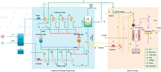
Figure 1.
Overview of the CAES-SOFC/MGT hybrid system.
Meanwhile, the first compressor of the charge chain works for the SOFC. The compressed air without cooling supplies the cathode. Additionally, prior to entering the fuel cell, the high-pressure air is heated using exhaust gas from the gas turbine, effectively utilizing the waste heat. The fuel cell generates power to the grid and the high-pressure, high-temperature by-product with the remaining fuel flows into the turbine to generate power too. In the discharge mode, the air turbines are also working in four stages. The gases coming into the air turbines are heated up by the transfer fluid in both the hot water tank and gas turbine. The cooling water goes to the cold water tank driven by the pump system.
2.1. CAES-SOFC/MGT Hybrid System Configuration and Description
The main working process of the advanced adiabatic compressed air energy storage system (AA-CAES) is divided into two separate processes, one is the charge process and the other is the discharge process. During off-peak periods, the air is pressurized and storage in the storage tank is maintained under a pressure of 100 bar. During peak periods, the compressed air is expanded to release back the stored energy through four air turbines to support the electrical grid. This paper mainly studies the dynamic characteristics of its discharge process, and the basic structure is shown in Figure 1. This system consists of a multi-stage turbine with inter-heating (four stages), a pump, an air storage tank, two fluid tanks (one for hot fluid and the other for cold fluid), an electric main air valve, and two pneumatically regulated air valves (parallel). The main air valve is used to cut off the intake air quickly in an emergency, and the pneumatic control valve is used for the rushing and power adjustment. The heat exchange medium in the hot tank heats the inlet air of the expanders through the inter-stage heat exchangers, which greatly improves the thermal efficiency of the system. The working process of the hybrid power generation system of compressed air energy storage, fuel cells, and gas turbines is mainly divided into two parts: the energy storage stage and the energy release stage.
As shown in Figure 1, the power generation energy storage system coupled with fuel cells and compressed air energy storage includes two subsystems. The compressed air energy storage system includes an air compressor unit, an energy release turbine unit, a cold water heat storage tank, a hot water heat storage tank, a gas storage tank, a generator, a motor, and a regenerator, of which the fuel cell power generation system includes a start-up burner, reactor, fuel cell body, post-combustor, post-combustion turbine, and generator.
The driving end of the motor is connected to the air compressor unit. When the power grid has surplus power, the motor is powered to drive the air compressor unit to compress the air. The air compressor unit includes multiple air compressors connected in series and two adjacent air compressors are connected through a heat exchanger. The input end of the air compressor unit is connected to the atmosphere, the first output end is connected to the input end of the gas storage device through a heat exchanger, and finally the high-pressure air is sent into the gas storage device. The gas storage device includes the first output end and the second output end, the gas storage device is connected with the energy release turbine group through the regenerator, and the energy release turbine group includes four energy release turbine groups in series. Between two adjacent energy release turbines, a heat exchanger is connected to provide enough heat to improve the inlet temperature of the turbines. The output end of the energy release turbine group is connected with the atmosphere through the energy release heat exchanger, and the driving end of the energy release turbine group is connected with the generator. The generator is connected to the grid, the anode of the fuel cell body is connected to the grid through an DC/AC converter, and the cathode and anode of the fuel cell body are connected to the input end of the afterburner.
In this study, the SOFC/MGT system consistently operates in a power generation state as the primary power generation system. The first-stage compressor is equipped with a spilt pipe that can supply high-pressure air to the fuel cell’s anode during system operation. Prior to entering the fuel cell, the high-pressure air undergoes heating through waste heat recovery from the microturbine’s exhaust.
The CAES system switches between different working states based on different requirements for energy storage and energy release. Generally speaking, some components in these operating states will not operate at the same time; for example, because energy storage and release do not occur at the same time, the air compressor and expander will not operate at the same time. Since the operation of the energy storage system has a time difference, in order to better analyze the operation of each component in each stage, this paper divides the operation of the entire system into five states, which can be seen from Figure 2.
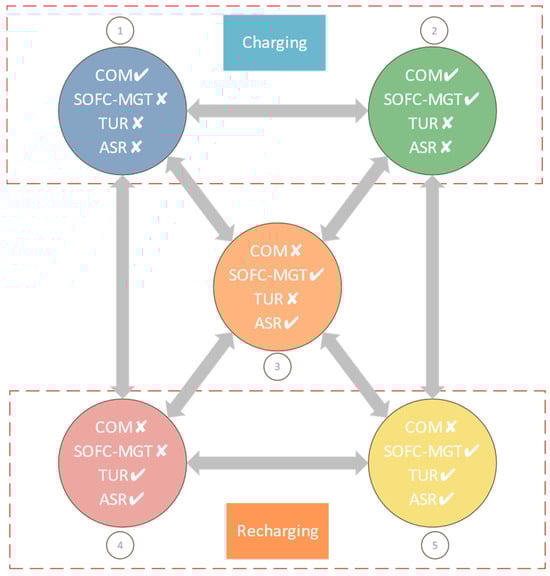
Figure 2.
Working states of the CAES-SOFC/MGT hybrid system. (COM: Compressors of CAES; SOFC-MGT: Solid oxide fuel cell and Micro gas turbine; TUR: Turbines of CAES; ASR: Air storage reservoir; Check mark: Subsystem is running; Cross mark: Subsystem is not running).
- Charging:
When the grid load is in its trough period, the grid supplies power to drive the air compressor unit. This unit compresses the air and stores it in the gas storage tank. During compression, the cold water from the tank’s cold water tank flows into the heat exchanger to cool the compressed air, and then flows into the hot water tank.
State 1 serves as a testing state used to assess the operational state of the compression chain when it operates independently. At this state, the air storage reservoir is in the energy storage stage, while other subsystems are inactive.
State 2 is the normal energy storage state of the system. At this state, excess power from the grid drives the compressor to produce compressed air. Some of the compressed air is stored in the air tank, while the rest is used as the cathode inlet air of the fuel cell, serving as the SOFC-MGT air source.
- 2.
- Black start:
State 3 serves as a testing state and represents the minimum system output power condition. It is utilized to assess the operational state of the SOFC-MGT system when it operates independently. In this state, the air tank serves as the air source of the SOFC-MGT system, and the compressed air is used as the cathode inlet of the fuel cell. When the air tank is fully charged, the SOFC-MGT system can provide compressed air to the entire system for hours or even days, depending on its capacity. Therefore, this state can be used as a reference for black start situations, where the energy storage system provides users with the minimum necessary output power when the external power grid is paralyzed.
- 3.
- Recharging:
State 4 is designed as a test state to evaluate the energy release chain’s working status when it operates independently. In this state, the compressed air from the air tank is supplied to the air turbine, and the hot water in the hot water tank and the regenerator between each stage heat the compressed air. This process allows the compression heat in the compression stage to be fully utilized.
State 5 characterizes the standard energy release state and corresponds to the system’s maximum output power. In this state, the compressed air in the air tank is split into two streams, of which one stream directly drives the air turbine to generate electricity, while the other stream serves as the anode inlet air for the SOFC-MGT system. Unlike state 4, the high-temperature exhaust gas at the outlet of the SOFC-MGT system heats the inlet air of the first-stage air turbine, allowing for the full utilization of the waste heat from the exhaust gas.
2.2. Assumption and Main Characteristics
The following assumptions are made to simplify the whole system modeling.
- (a)
- The composition of air in the CAES system and SOFC cathode inlet consists of 79% N2 and 21% O2 (mole fraction).
- (b)
- The parameters in each calculation area are evenly distributed (such as temperature, pressure, and gas composition).
- (c)
- The heat and pressure loss in the pipes connecting all the components can be negligible.
- (d)
- The inlet enthalpy of the throttle valve is identical to that of the outlet.
- (e)
- All the kinetic and potential effects are ignored.
- (f)
- The storage tank is adiabatic during the charging and discharging process.
- (g)
- Due to the high conductivity of the connecting material, the effect of the connecting material on the ohmic polarization loss is negligible.
- (h)
- The water–gas reaction is in a state of chemical equilibrium.
- (i)
- The fuel reforming reaction occurs on the surface of the SOFC anode material.
- (j)
- The effect of radiation heat transfer is not considered.
- (k)
- Heat conduction between air streams is negligible.
- (l)
- The system operates under steady-state conditions.
- (m)
- The isentropic efficiency of each compressor and turbine is fixed.
Basic geometric and operating parameters of this hybrid system are shown in Table 2 and Table 3. The SOFC geometric parameters were taken from [41].
Table 2.
Basic operating parameters for CAES.
Table 3.
Basic operating parameters for SOFC/GT hybrid system.
2.3. Compressor
The system comprises four air compressors connected in series, featuring interstage coolers between each compressor and an aftercooler following the fourth air compressor. The outlet pressure of the air compressor can be calculated using the following formula [13]:
where is the inlet pressure of the compressor, is the compression ratio of the air compressor, and the inlet pressure of the first stage compressor is atmospheric pressure. The outlet temperature of the compressor is
where is the inlet temperature and is the isentropic efficiency of the compressor. K is the specific heat ratio. The power consumed by the compressor is
where is the inlet air mass flow rate of the air compressor in the energy storage stage, and and are the specific enthalpy of the outlet and inlet air, respectively.
2.4. Heat Exchanger
The heat generated during compression is transferred to the heat storage device through the inter-stage heat exchanger. This paper employs a counter-flow heat exchanger for this purpose. Prior to entering the interstage cooler, the water temperature is approximately at ambient temperature. From the law of conservation of energy [14]:
where and are the air-specific enthalpy at the inlet and outlet of the interstage cooler, respectively; and are the specific enthalpy of the water in the heat storage system at the inlet and outlet of the interstage cooler, respectively; is the thermal conductivity of the heat exchanger; is the heat transfer area; and is the average temperature difference between air and water.
Each turbine is equipped with a regenerator, similar to the energy storage component, and it functions as a counter-flow heat exchanger. Within the regenerator, hot water from the hot water tank is used to heat the air as it exits the air storage tank, and then the air is cooled to ambient temperature in the cold water tank.
where and are the specific enthalpy of air at the inlet and outlet of the regenerator, respectively; and and are the specific enthalpy of water at the inlet and outlet of the regenerator, respectively.
2.5. Turbine
In this paper, four turbines are connected in series. The outlet pressure of the turbine can be calculated using the following formula [13,42]:
where is the inlet pressure of the turbine, is the expansion ratio of the turbine, and the inlet pressure of the first stage turbine is the outlet pressure of the gas storage tank. The outlet temperature of the turbine is
where is the inlet temperature of the turbine and is the isentropic efficiency of the turbine. k is the specific heat ratio. Turbine work can be calculated using the following formula:
2.6. Air Storage Tank
After flowing out of the interstage cooler, the hot water absorbing the heat of compression will be stored in the hot water tank.
In this paper, the gas storage device adopts the gas storage tank. In order to study the performance of the gas storage tank, according to the law of mass conservation and energy conservation [42,43]:
where and are the rates of transferred heat; is the air flow rate; tc and tt are the charge time and discharge time, respectively; and the subscript split represents air split from tank in mode 5.
2.7. SOFC
The SOFC power generation system comprises four primary components: a fuel processing system, a fuel cell stack, a recirculation system, and a DC/AC conversion system. The process begins with desulfurized natural gas and superheated water vapor undergoing reforming in an ATR (Autothermal Reformer) before entering the SOFC’s anode. This transformation converts the fuel into a hydrogen-rich gas. Simultaneously, pressurized and heated air enters the cathode and dissociates oxygen into oxygen ions, which are transported through the solid oxide electrolyte to the anode. At the anode, hydrogen and oxygen ions combine with electrons from an external circuit, producing both electricity and water. The exhaust gas from the battery stack, containing unreacted fuel, is combusted in a burner, and the turbine captures the flue gas to generate the electric energy. The exhaust heat from the turbine is used to heat the feedwater, producing the steam necessary for the reforming reaction. Additionally, the waste heat from the exhaust gas is employed to incrementally heat the air, fuel, and water vapor to achieve the required reaction temperature. Finally, the direct current generated by the battery stack is converted into alternating current by a high-efficiency inverter, supplying power to external alternating current devices or the grid.
The SOFC model used the lumped parameter method to calculate the local current density, distribution temperature distribution, Nernst potential, and electrochemical loss of the whole fuel cell. The chemical kinetic model was used to calculate the water–gas-shift reaction, steam methane reforming reaction, and electrochemical reaction. The SOFC model was created in an ACM and imported into Aspen PlusTM. The current density can be calculated based on the feed flow rate of each component of the inlet fuel and the set fuel utilization rate. The operating conditions of the fuel cell are modeled in terms of inlet and outlet average temperatures, pressures, and stream composition. The cell voltage is calculated using the Bulter–Volmer formula, and the power output of a fuel cell can be calculated based on the total reaction area of the cell and the total number of cells. Liese E A, et al. published a detailed description of the model and validation work. The electrochemical loss and cell voltage calculations are expressed by the following equations [44].
This paper uses the ACM model in the Aspen Plus TM software (V12.1) model library to establish the SOFC battery model. Before flowing into the cathode, part of the air is split into the reformer, combusted with part of the fuel to make the reformer an autothermal reformer and ensure the temperature of the fuel at the anode inlet. The remaining air is discharged after exchanging heat with SOFC’s outlet flue gas in the heat exchanger, while ensuring the inlet temperature of the after burner. At the anode, the natural gas undergoes a reforming reaction, and the produced hydrogen reacts electrochemically with the air from the cathode to generate electricity.
The input data for natural gas, air volume, and water vapor required for the stack model were determined using the calculator model of Aspen Plus TM. Assuming that the cells in the stack are connected in parallel, the voltage of each battery is the same. The current of the fuel cell stack is equal to the current per cell multiplied by the number of cells, which was calculated in the SOFC ACM model.
2.8. Validation of the CAES and SOFC/MGT Models
The developed models for the compressed air storage reservoir were validated by performing a comparative analysis with the results presented in [42], where a numerical methodology based on thermodynamic considerations was used to estimate the exergy storage capacity in caverns. This methodology was validated using operational data from a CAES plant in China. Table 4 presents a comparison between the results obtained through the developed models and those available in [42]. As the system in this article is a new system, the design of the compressor chain and turbine chain take into account the supply of compressed air to the SOFC. Therefore, the compression ratio and expansion ratio are slightly different from those values in the reference literature. In this system, the first-stage compressor functions not only as the first stage in the compression chain, but also to provide compressed air for subsequent compressors. Another function of the first-stage compressor is to provide a certain flow rate of compressed air to the SOFC during the gas storage stage. It is worth noting that, as can be seen in the system schematic diagram in Figure 1, the first-stage compressor has a split flow. In order to better provide the required pressure (rated 3.9 bar) for the SOFC, the design of the first-stage compressor in this article is different from the traditional AA-CAES. In addition, when the pressure ratio of the first-stage compressor is high, the temperature of the compressed air at the outlet is also high, which can reduce the heat required for the airflow to the SOFC cathode inlet to reach the rated temperature, reduce the load on the heat exchanger, and further reduce exergy loss of the SOFC section heat exchanger. Furthermore, although the first-stage compressor does more work when the pressure ratio is higher, the pressure ratios of subsequent stages of compressors can be reduced, thereby reducing the pressure fluctuations in the gas storage tank. However, the trend of the operational data indicates that it is consistent with the reference literature. It was concluded that the CAES model is valid for the present study. From a system operation trend perspective, the design of this model is reliable.
Table 4.
Comparison of CAES model results and the results available in [42].
This study employs an autothermal reformer (ATR), a system in which fuel and air are pre-heated before entering the reactor. Inside the ATR, they react with steam under high temperature and pressure, resulting in the production of gases like hydrogen, carbon monoxide, and carbon dioxide. The heat generated during this reaction helps maintain the reactor’s temperature, achieving self-heating. One notable advantage of the ATR device is its capability to simultaneously perform combustion and reforming reactions, leading to enhanced production efficiency and higher hydrogen yield. The ATR model utilized in this research is constructed using the Gibbs free energy reactor within Aspen Plus TM. This particular reactor employs the Gibbs free energy minimization method to calculate the mole fraction of each component in the equilibrium state of the chemical reaction. The changes in the outlet components at different ATR temperatures in this paper can be seen in Figure 3. Under the operating conditions of a working temperature of 727 °C and working pressure of 390 kPa, the reactants of CH4/H2O=1/2 were passed into the Aspen Plus TM Gibbs free energy reactor and the reformer model (reformer model) constructed above. The comparison results with [41] are shown in Table 5, and the maximum absolute error of the calculation results is shown in the N2 mole fraction. This is because the reference uses a 1-D ATR model, considering the kinetic reaction and reaction equilibrium constants. Thus, the outlet composition of the reformer also varies with temperature, as shown in Figure 3. It can be seen from the figure that the main fuel for the SOFC, hydrogen, reaches its highest level at 727 to 800 °C with a mole fraction of about 35%.
Table 5.
Results’ comparison of the literature and Aspen Plus TM reformer model.
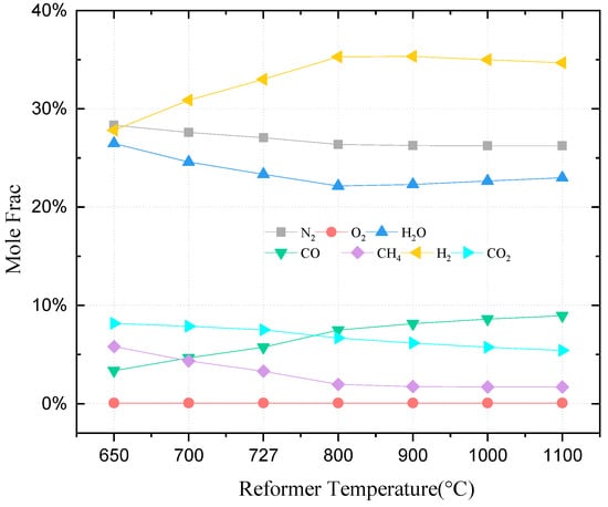
Figure 3.
Impacts of fuel reforming temperature on ATR composition.
Figure 3 illustrates the polarization curve comparison between the fuel cell model and the reference literature. The fuel cell operates at an average temperature of 725 °C, atmospheric pressure, and a fuel utilization of 62.5%. The anode gas composition is set as the ATR outlet composition above. To achieve a power density of about 0.5 W cm2, which is a realistic performance for a methane-fueled SOFC, a nominal single-cell voltage of 0.78 V is chosen. This voltage and power density correspond to a current density of about 0.67 A/cm2. The SOFC stack is designed to operate at this nominal voltage, generating about 1 MW net power. Figure 4 demonstrates that the model proposed in this study and the values reported in the reference literature exhibit a high degree of consistency in both the relative error of the data and overall trend.
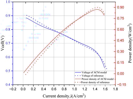
Figure 4.
SOFC model polarization curve for comparison with the literature [45] data.
3. Thermodynamic Model
The hybrid energy system under examination is a highly intricate energy system, amenable to characterization via both energy and exergy efficiency evaluations. These evaluations are conducted through energy and exergy analyses, collectively known as thermodynamic analysis methods. Energy analysis hinges on the first law of thermodynamics, primarily considering the quantity of energy within the system. However, it is limited in its ability to reveal the quality of energy wasted due to inefficiencies in the system’s components. On the other hand, exergy analysis, grounded in the second law of thermodynamics, delves deeper into the assessment of the thermodynamic perfection of energy-using equipment. It unveils details such as the size, location, and factors contributing to the loss of energy quality. Exergy analysis has found extensive utility across various engineering domains, including investigations into heat pumps, air conditioning refrigeration systems, building energy systems, power generation systems, and various types of equipment. Exergy analysis is a process energy analysis method based on the second law of thermodynamics. It not only quantifies the amount of energy, but also defines the quality of energy. By analyzing the exergy loss and distribution in the various components of the system, the improvement direction and feasibility of the system can be better revealed in Figure 5. The exergy value is calculated based on the environmental reference state, which refers to the state of the reference material system at a specified temperature and pressure. The standard for exergy specifies that the reference state temperature is 298.15 K (25 °C), and the reference state pressure is 1 atm. Table 6 presents the energy balance and exergy balance of components in the hybrid system, while Table 7 shows the standard exergy and standard enthalpy of system reaction compounds [46].
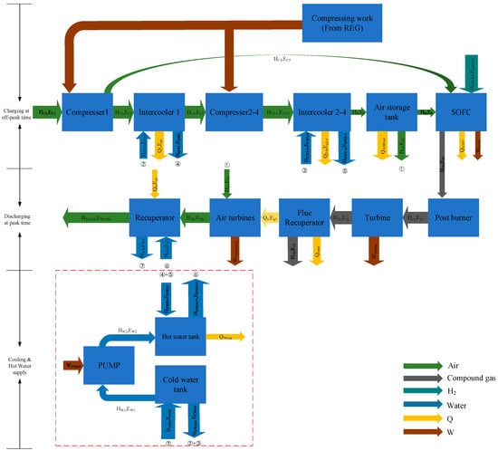
Figure 5.
Energy flow diagram of CAES-SOFC/MGT hybrid system.
Table 6.
Energy and exergy balance of each component of the hybrid system [46].
Table 7.
Standard exergy and standard enthalpy of system reaction compounds [46].
Analyzing a hybrid power system that incorporates an energy storage component presents a challenge when attempting to establish a precise efficiency value. This complexity arises due to the charging and discharging phases occurring at distinct times within the system’s operation. In such cases, the system’s round-trip efficiency (RTE) is used as a metric. RTE is the ratio of total electrical energy output to the total fuel and electrical energy input for a full charge/discharge cycle and can be calculated using the following formula:
where is the electricity output, is the energy input, is the electricity generation for expanders, is the electricity generation for the turbine, and is the excess heat load in the hot water tank for the end user. is the electricity generation for an SOFC, is the electricity consumption of compressors, is the mass flow of inlet CH4, is the lower heating value of CH4, is the discharge time, is the charge time, and is the one-cycle time.
Similar to the definition of system cycle efficiency, total exergy efficiency (TEE) is defined as the total net exergy output in the discharging process to the total net exergy input in the charging process. As the heating exergy is not considered in the reference, TEE can be presented as
where is the total exergy of expanders, is the total exergy of compressors, is the total exergy of SOFC, is the total exergy of the turbine, and is the total exergy of fuel.
4. Results and Discussion
4.1. Influence of Ambient Temperature
A rise in the temperature of the environment results in a corresponding increase in the temperature of the inlet air, inlet water, and inlet fuel for this system. The density of air decreases as temperature increases, requiring more energy to compress the same amount of air to the same pressure, which can be seen from Figure 6. This leads to a decrease in the RTE, as compressor electricity consumption increases. Meanwhile, the rising trend in temperature of fuel and water will reduce the heat load, resulting in the power generated by the SOFC growing marginally, while the power generated by the MGT increases slightly due to the rising inlet temperature. The air turbines remain relatively stable. Figure 7 and Figure 8 illustrate the impact of ambient temperature on the hybrid system’s RTE and exergy efficiency. Figure 8 shows the effect of expansion valve outlet pressure on the total exergy efficiency. In the figure, nECOM represents the exergy efficiency of the compressor, nETUR represents the exergy efficiency of the expander, nESOFC-MGT represents the exergy efficiency of SOFC-MGT, and EXALL represents the exergy efficiency of the system total exergy efficiency.
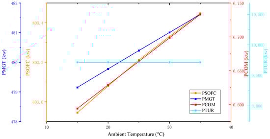
Figure 6.
Effect of ambient temperature on main components.
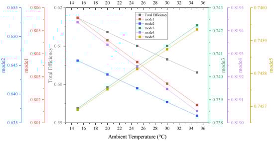
Figure 7.
Effect of ambient temperature on RTE.
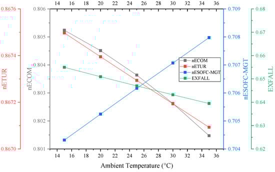
Figure 8.
Effect of ambient temperature on TEE.
The overall exergy efficiency decreases slightly when the ambient temperature increases from 15 °C to 35 °C. Based on Figure 8, it can be inferred that the rise in environmental temperature exhibits a minor influence on the aggregate exergy efficiency of the system as a whole. The reference ambient temperature used for calculating the exergy of each component is adjusted to correspond with the temperature of the air, fuel, and water entering the system. If the heat lost to the ambient temperature of the heat exchanger, air storage tank, and SOFC is disregarded, the impact on the exergy difference of each component is minimal. However, the TEE decreases with the increase in ambient temperature, while the temperature change may have varying impacts on different sub-modes and components. In general, lower ambient temperatures benefit the hybrid system’s performance more.
Considering the different working states of the hybrid system, in the process of analyzing the RTE and TEE process, this article also calculates the performance of the system under different modes (corresponding to state1–state5). Regarding compression stage mode 1 and mode 2, elevated temperatures are deleterious to the exergy efficiency of the subsystems. In mode 4, which maintains a constant-air-turbine-inlet-temperature setting, an upsurge in ambient temperature may result in a reduction in RTE due to the decline in temperature difference across the intercooler, hence decreasing exergy loss in the heat exchanger. Nevertheless, a temperature rise also leads to an elevation in the air turbine inlet temperature.
As for mode 3 and mode 5, a temperature rise exhibits a more significant positive impact on the MGT and SOFC, and thus, the RTE of these two modes increases slightly. Overall, under the current system configuration, the RTE of a complete cycle is marginally reduced with an increase in ambient temperature. Consequently, this effect could be considered in engineering applications, which indicates from a typical daily perspective that when the power grid is in the nighttime low-peak period, the lower environmental temperature is advantageous for energy storage. The system performance will be reflected in in seasonal and regional differences as well.
4.2. Influence of Outlet Pressure of Expansion Valve
In the discharging process, the air from the ASR passes through the expansion valve so that a specific pressure will be set, which makes the turbines operate at steady and high-efficiency conditions. The change in the required pressure has a direct influence on the turbines’ performance. The power output of the turbine and the mass flow rate of air increase with increasing pressure behind the expansion valve. However, the operating range of the turbine narrows, and the discharge time decreases sharply. The 0-D system model lacks a control mechanism, resulting in changes in mass flow rate in response to pressure variations. As shown in Figure 9, modes 4 and mode 5’s efficiencies rise with increasing post-valve pressure. The throttle valve has no impact on the operation of the compression chain and SOFC/MGT subsystems. Hence, the efficiencies of modes 1, 2, and 3 remain unchanged. As pressure behind the valve rises gradually, the system RTE drops from 65.9% to 49.6%. The reason is that although the turbine does more work per unit of time, the release time for energy decreases, which reduces the working range of the air storage tank, ultimately decreasing the total work done by the turbine.
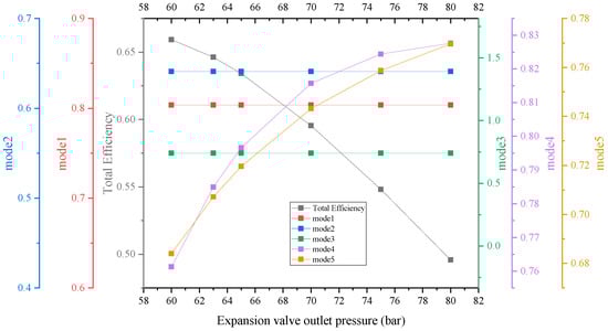
Figure 9.
Effect of expansion valve outlet pressure on RTE.
It should be emphasized that this experiment is not feasible at a pressure of 60 bar behind the valve without additional heating for the turbine regenerator. This is due to the possibility that the combined heat generated by compression and supplied by the SOFC/MGT system may not be sufficient to meet the heat requirements of the turbine reheater. Based on calculations, the system configuration in its current state can operate without additional heat input when the pressure after the expansion valve is set to 62 bar. However, the heat load delivered to users at this operating point is zero.
As seen from Figure 10, the TEE of the compressor chain and SOFC/GT subsystem remain constant as well. But turbine chain subsystem’s TEE increases with the varying expansion valve outlet pressure from 60 bar to 80 bar. It is evident that when the inlet pressure is increased, each turbine performs more work, leading to an increase in exergy efficiency. While the flow rate also rises, requiring more hot water heat and leading to greater exergy loss in the turbine chain’s regenerator, these effects are relatively minor in comparison to the gain in exergy efficiency resulting from the increased work done by the turbines. However, TEE exhibits a clear downward trend. This is due to the significant reduction in the energy release time, despite the increase in work done per unit time by the turbine. Compared to the aforementioned effects, the energy discharge time has a greater impact on the total output exergy. In conclusion, the highest achievable values of the overall system’s round-trip efficiency and exergy efficiency are obtained when the heat load output to the user approaches zero, while the turbine maximizes the use of the compression heat and SOFC/MGT exhaust waste heat.
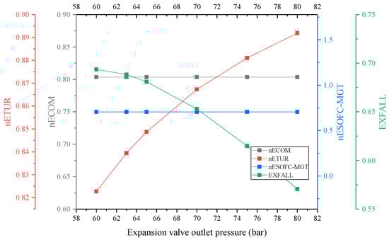
Figure 10.
Effect of expansion valve outlet pressure on TEE.
4.3. Influence of Compressor Isentropic Efficiency and Turbine Isentropic Efficiency
Based on the literature [32], it is evident that both the compressor and turbine’s isentropic efficiency is a critical parameter that significantly affects system efficiency. The isentropic efficiency of either component can be enhanced to increase the RTE of the system, as shown by Figure 11 and Figure 12, when the isentropic efficiency of the compressor and the turbine ranges between 80% and 90%. Notably, the compressor is more affected by changes in isentropic efficiency compared to the air turbine due to its upstream position in the system, directly influencing the heat of compression and the compressed air inlet temperature of the SOFC/MGT subsystem.
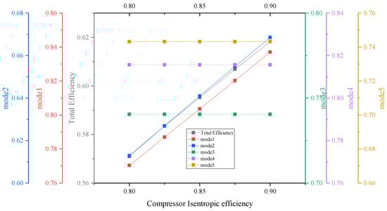
Figure 11.
Effect of compressor isentropic efficiency on RTE.
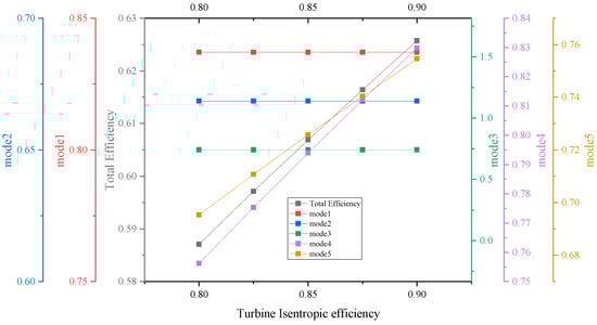
Figure 12.
Effect of turbine isentropic efficiency on RTE.
The isentropic efficiency of both the compressor and turbine has a direct impact on the exergy efficiency of the system. This is due to the fact that the closer the process approaches the isentropic adiabatic process, the lower the exergy losses of both the compressor and turbine. Figure 13 and Figure 14 indicate that the TEE of the system increases with the enhancement in the isentropic efficiency of both components. It is worth noting that, similar to the finding on RTE, the increase in the isentropic efficiency of the compressor has a more significant impact on the increase in exergy efficiency. Indeed, the isentropic efficiency of compressors and turbines is a critical factor for achieving high system efficiency in practical engineering applications. As such, design optimization of these components can be pursued to enhance RTE and TEE. This optimization can include impeller design optimization and control optimization of working conditions, among others. By considering these factors during the design and manufacture of the components, it is possible to improve their isentropic efficiency and thereby enhance the overall performance of the system.
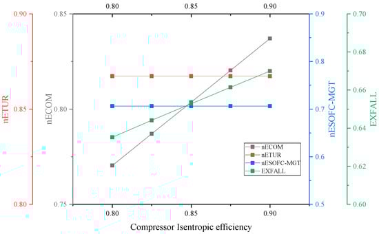
Figure 13.
Effect of compressor isentropic efficiency on TEE.
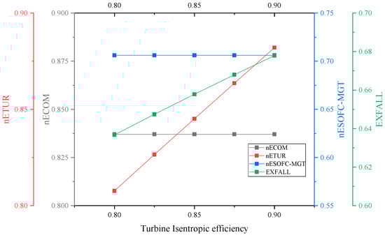
Figure 14.
Effect of turbine isentropic efficiency on TEE.
4.4. Influence of Fuel Utilization Factor and Air Mass Flow on SOFC/MGT System
Figure 15 presents a comprehensive analysis of the impact of varying the fuel utilization factor and SOFC/MGT air inlet mass flow on the efficiency of the hybrid system in different operating modes. Specifically, the figure demonstrates the effect of changing the aforementioned parameters on the overall efficiency of the hybrid system as well as the efficiencies of the individual subsystems in different operating modes. As illustrated in Figure 15a, the compressed air flow rate is the main factor affecting mode 1, which refers to the compression chain of the CAES system. When the compressed air flow rate diverted to the SOFC/MGT system increases, the flow rate of the compressor decreases. Consequently, the power consumption of stages 2–4 of the compressor decreases, along with a reduction in the compression heat. However, this also leads to a significant decrease in the energy stored per unit time, resulting in a reduction in the efficiency of mode 1. Because the efficiency reduction of the compressor is so large that even though the efficiency of the SOFC/MGT system has increased due to the change in Uf, the efficiency in mode 2 is still reduced, a higher Uf will result in higher efficiency, as shown in Figure 15b. The efficiency of mode 3 is directly affected by the variation in Uf and the SOFC/MGT inlet flow rate. A high fuel utilization rate can reduce the fuel cell efficiency, and a large anode air flow can lower the average temperature of the fuel cell. However, since the compressed air in mode 3 mainly comes from the CAES subsystem’s compressor, a high fuel utilization rate leads to higher efficiency in mode 3. On the other hand, an increase in SOFC anode air reduces the heat output from the SOFC/MGT subsystem to the downstream, resulting in a decrease in efficiency. As shown in Figure 15d, the increase in system efficiency is observed only at the energy release end of the CAES system. This is because the work done by the turbine per unit time remains unchanged, but the heat output to the turbine decreases. Combining the turbines with the SOFC/MGT, it can be seen that the efficiency reduction of the SOFC/MGT subsystem has a greater impact, so the efficiency under mode 5 is reduced. Overall, the hybrid system’s efficiency increases as fuel utilization increases, considering the changes in energy storage and release times due to variations in air flow. When fuel utilization is low, the SOFC/MGT subsystem’s air flow has a positive effect on RTE. However, at high fuel utilization rates, the SOFC/MGT subsystem’s air flow has a negative effect on RTE.
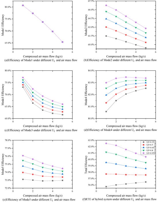
Figure 15.
Effects of different fuel utilization rates and cathode compressed air flow rates on the RTE of hybrid systems.
Figure 16 depicts the exergy efficiency of each subsystem and the overall system as a function of Uf and the inlet air flow rate to the SOFC/MGT subsystem, while Figure 17 shows the variation in exergy loss of each main component and its proportion in the system under different combinations of Uf and inlet air flow rate. In these figures, Uf varies between 0.35 and 0.95, and the inlet air flow rate changes from 1 kg/s to 5 kg/s. The performance of the SOFC is strongly affected by Uf, which, in turn, impacts the performance of downstream components, such as the afterburner, MGT, and turbine chain. As shown in Figure 16, the exergy efficiency of the SOFC/MGT subsystem increases with Uf since a higher fuel utilization rate results in higher hydrogen reacting in the SOFC and, consequently, a higher electric energy output. Additionally, the outlet temperature of the fuel cell is also higher, which reduces the combustible gas entering the combustion chamber downstream, leading to a reduction in the exergy loss of the combustion chamber. Consequently, the exergy loss of the MGT also decreases, and the degree of decrease has little effect on the decrease in the MGT’s output work compared to the increase in the output work brought by the increase in the turbine inlet flow. The highest exergy efficiency of the solid SOFC/MGT subsystem is achieved when Uf is 95% and the inlet air flow rate is 5 kg/s.
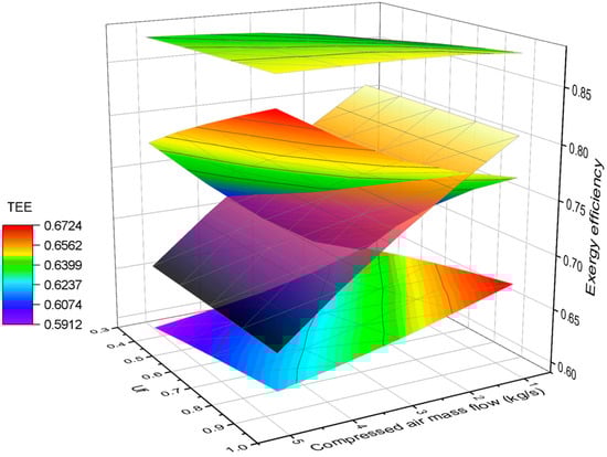
Figure 16.
Effect of variation in SOFC/MGT Uf and inlet air mass flow on TEE.
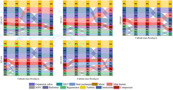
Figure 17.
Percentage contribution of exergy destruction by each component with rise in air mass flow to SOFC/MGT subsystem at varying fuel utilization factors.
When the air flow to the SOFC/MGT subsystem increases, the flow rate of the 2–4 stage compressors in the compression chain of the CAES system decreases, and the power consumption also decreases, leading to a significant reduction in the compression heat of the entire compression chain. Furthermore, the exergy loss of the interstage cooler is reduced. As a result, the total exergy efficiency of the compression chain increases with an increase in the air flow diverted to the SOFC/MGT system. However, after a complete cycle, the split air flow rate reaches 5 kg/s, and the difference between the heat of compression and the heat required for expansion of the entire system is negative, indicating that the system can no longer operate completely without additional external heat supply. For the energy release chain of CAES, the input work of the turbine remains unchanged since the turbine inlet temperature and air flow rate remain constant. However, due to the reduction in the exhaust gas temperature of the SOFC/MGT system, the exergy loss of the heat exchanger between the compressed gas tank and the turbine chain is reduced, and the exergy efficiency of the solid-release energy chain slightly increases. Based on the analysis above, combined with Figure 17, it can be concluded that for the entire hybrid system, the compression chain exergy loss of CAES is more sensitive to air flow changes, while SOFC/MGT has little effect on the exergy loss of the entire system. Therefore, the highest total exergy efficiency is 67.24%, which increases with the increase in Uf and inlet air flow rate of the SOFC/MGT.
5. Conclusions
This study presents a thermodynamic analysis of a novel hybrid CAES/SOFC/MGT generation system. A reliable static model of the system was established using ASPEN Customer Modeler TM and Aspen Plus TM, and simulation experiments were conducted on key parameters to investigate the operating conditions of different subsystems and the overall system, in order to establish a reliable power generation and energy storage system. The following are some of the main results:
- When the atmospheric temperature is 25 °C, the atmospheric pressure is 1 atm, Uf = 0.62, kg/s, kg/s, the hybrid system RTE of this system is 59.6%, and the TEE is 65.2% under design conditions. Although RTE may be slightly lower than traditional AA-CAES, the new hybrid system in this paper has a higher flexibility and better utilization of waste heat.
- The influence of different parameters on the performance of the hybrid system was evaluated using a parametric analysis. This study’s findings suggest that to enhance the system’s RTE and TEE, it is advisable to operate the system under lower ambient temperatures of 25 °C, higher compressor and turbine isentropic efficiencies of 0.9, a higher fuel utilization of 0.62, and optimal SOFC/MGT split air flow rates of 1.1 kg/s. Indeed, while these data may be influenced by environmental temperature, it is important to acknowledge that other parameters could vary depending on the specific design of the system. However, as a general principle, the direction of increase in round-trip efficiency (RTE) and total exergy efficiency (TEE), as well as the reduction in exergy losses, will invariably be closely linked to the design values of these critical parameters within the context of this paper. These findings can be employed in future system design and modeling endeavors to perform multi-objective optimization, leading to superior system performance.
- The effects of changes in multiple key system input parameters on efficiency and exergy efficiency were analyzed under different working modes and subsystems, which can better help to perform individual optimization of the actual operating conditions of the entire system.
The results offer valuable insights into the optimal operating conditions and design parameters for the system and can aid in the development of more efficient and cost-effective energy storage and generation solutions. Nevertheless, the static analysis approach proposed in this study provides valuable guidance for future system improvement and optimization. Furthermore, the model results obtained in this study not only serve as a valuable data source for dynamic model establishment, but also lay a foundation for multi-objective optimization of the system. Therefore, the value of the system designed parameters should be selected wisely. Moreover, based on the findings of this study, the commercial potential of the system warrants further exploration. However, in light of potential practical applications of our system in the future, it becomes imperative to address power coordination between the power generation and energy storage components during the system’s construction phase. This entails that during the initial system design stage, careful consideration must be given to the local electrical grid, user load requirements, and the proportion of renewable energy sources integrated into the broader grid context.
Subsequently, upon determination of the load patterns within the electrical grid, calculations for the energy storage system’s capacity can be accurately computed. Furthermore, meticulous power matching for the SOFC/MGT system, which functions as the base load provider, can be systematically achieved. In summation, it is essential to underscore that all of these intricate calculations can be corroborated and referenced based on the substantive findings delineated within this research endeavor.
Author Contributions
Conceptualization, C.Y. and L.S.; methodology, C.Y.; software, L.S. and H.C.; validation, C.Y. and L.S.; formal analysis, C.Y.; investigation, C.Y.; resources, C.Y.; data curation, C.Y. and L.S.; writing—original draft preparation, C.Y. and Xiaosheng; writing—review and editing, C.Y.; visualization, L.S. and H.C.; supervision, C.Y.; project administration, C.Y.; funding acquisition, C.Y. All authors have read and agreed to the published version of the manuscript.
Funding
This work was supported by the National Natural Science Foundation of China, grant number 51876011.
Data Availability Statement
Data available on request due to restrictions eg privacy or ethical. The data presented in this study are available on request from the corresponding author. The data are not publicly available due to the privacy involved in the project.
Acknowledgments
The authors extend their appreciation to the National Nature Science Foundation of China through grant number 51876011.
Conflicts of Interest
The authors declare no conflict of interest.
Nomenclature
| Abbreviations | |
| CAES | Compressed air energy storage |
| SOFC | Solid oxide fuel cell |
| MGT | Micro gas turbine |
| AFC | Alkaline fuel cell |
| PAFC | Phosphoric acid fuel cells |
| MCFC | Molten carbonate fuel cell |
| PEMFC | Proton exchange membrane fuel cell |
| DMFC | Direct-methanol fuel cells |
| A-CAES | Adiabatic compressed air energy storage |
| AA-CAES | Advanced adiabatic compressed air energy storage |
| I-CAES | Isothermal compressed air energy storage |
| D-CAES | Diabatic compressed air energy storage |
| AC | Alternating current |
| DC | Direct current |
| LHV | Lower heating value (kJ∙mol) |
| RTE | Round-trip efficiency |
| TEE | Total exergy efficiency |
| Parameters | |
| P | Pressure (Pa) |
| T | Temperature (K) |
| W | Work (J) |
| EX | Exergy (kW) |
| h | enthalpy (kJ∙kg−1) |
| π | Compression ratio |
| k | Specific heat ratio |
| m | Mass flow (kg/s) |
| Cp | Heat capacity at constant pressure (J/K) |
| Q | Amount of heat (kJ) |
| λ | Efficiency |
| A | Area (m2) |
| μ | Thermal conductivity (W/m·K) |
| V | Voltage (V) |
| η | Polarization loss (V) |
| Χ | Mole fraction |
| α | Transmission coefficient |
| I | Exergy loss (kW) |
| Uf | Fuel utilization |
| E | Potential (V) |
| R | Molar gas constant (J·K−1·mol−1) |
| F | Faraday constant (C∙mol−1) |
| i | Current density (A/cm2) |
| Subscripts | |
| out | Outlet |
| in | Inlet |
| c | Compressor |
| inter | Intercooler |
| re | Regenerator |
| t | Turbine |
| Nernst | Nernst potential |
| act | Activation |
| con | Concentration |
| ohm | Ohmic |
| split | Split after 1st compressor |
References
- IPCC. Climate Change 2022: Mitigation of Climate Change. Contribution of Working Group III to the Sixth Assessment Report of the Intergovernmental Panel on Climate Change; Shukla, P.R., Skea, J., Slade, R., Al Khourdajie, A., van Diemen, R., McCollum, D., Pathak, M., Some, S., Vyas, P., Fradera, R., et al., Eds.; Cambridge University Press: Cambridge, UK; New York, NY, USA, 2023. [Google Scholar] [CrossRef]
- Gates, B. How to Avoid a Climate Disaster; Diversified Publishing: Murfreesboro, TN, USA, 2021; pp. 196–197. ISBN 978-0593215777. [Google Scholar]
- Bazdar, E.; Sameti, M.; Nasiri, F.; Haghighat, F. Compressed air energy storage in integrated energy systems: A review. Renew. Sustain. Energy Rev. 2022, 167, 112701. [Google Scholar]
- Zhang, W.; Xue, X.; Liu, F.; Mei, S. Modelling and experimental validation of advanced adiabatic compressed air energy storage with off-design heat exchanger. IET Renew. Power Gener. 2020, 14, 389–398. [Google Scholar] [CrossRef]
- Grazzini, G.; Milazzo, A. Thermodynamic analysis of CAES/TES systems for renewable energy plants. Renew. Energy 2008, 33, 1998–2006. [Google Scholar] [CrossRef]
- Menéndez, J.; Ordóñez, A.; Álvarez, R.; Loredo, J. Energy from closed mines: Underground energy storage and geothermal applications. Renew. Sustain. Energy Rev. 2019, 108, 498–512. [Google Scholar]
- Li, Y.; Miao, S.; Yin, B.; Han, J.; Zhang, S.; Wang, J.; Luo, X. Combined heat and power dispatch considering advanced adiabatic compressed air energy storage for wind power accommodation. Energy Convers. Manag. 2019, 200, 112091. [Google Scholar] [CrossRef]
- Olabi, A.G. Renewable energy and energy storage systems. Energy 2017, 136, 1–6. [Google Scholar]
- Luo, X.; Wang, J.; Dooner, M.; Clarke, J. Overview of current development in electrical energy storage technologies and the application potential in power system operation. Appl. Energy 2015, 137, 511–536. [Google Scholar]
- Wang, J.; Lu, K.; Ma, L.; Wang, J.; Dooner, M.; Miao, S.; Li, J.; Wang, D. Overview of compressed air energy storage and technology development. Energies 2017, 10, 991. [Google Scholar] [CrossRef]
- Sciacovelli, A.; Li, Y.; Chen, H.; Wu, Y.; Wang, J.; Garvey, S.; Ding, Y. Dynamic simulation of Adiabatic Compressed Air Energy Storage (A-CAES) plant with integrated thermal storage–Link between components performance and plant performance. Appl. Energy 2017, 185, 16–28. [Google Scholar]
- Mohamed, A. Isothermal Compressed Air Energy Storage (I-CAES). Master’s Thesis, Vienna University of Technology, Vienna, Austria, 2018. [Google Scholar]
- Hartmann, N.; Vöhringer, O.; Kruck, C.; Eltrop, L. Simulation and analysis of different adiabatic compressed air energy storage plant configurations. Appl. Energy 2012, 93, 541–548. [Google Scholar] [CrossRef]
- Guo, C.; Xu, Y.; Zhang, X.; Guo, H.; Zhou, X.; Liu, C.; Qin, W.; Li, W.; Dou, B.; Chen, H. Performance analysis of compressed air energy storage systems considering dynamic characteristics of compressed air storage. Energy 2017, 135, 876–888. [Google Scholar] [CrossRef]
- Grove, W.R. XXIV. On voltaic series and the combination of gases by platinum. Lond. Edinb. Dublin Philos. Mag. J. Sci. 1839, 14, 127–130. [Google Scholar] [CrossRef]
- Saikia, K.; Kakati, B.K.; Boro, B.; Verma, A. Current Advances and Applications of Fuel Cell Technologies. In Recent Advancements in Biofuels and Bioenergy Utilization; Springer: Singapore, 2018; pp. 303–337. [Google Scholar]
- Chen, H.; Yang, C.; Zhang, B.; Zhou, N.; Harun, N.F.; Oryshchyn, D.; Tucker, D. Coupling effects of fuel reforming process and fuel utilization on the system performance of a natural gas solid oxide fuel cell/gas turbine hybrid system. Int. J. Energy Res. 2021, 45, 17664–17690. [Google Scholar] [CrossRef]
- Williams, M.C.; Strakey, J.P.; Singhal, S.C. U.S. distributed generation fuel cell program. J. Power Sources 2004, 131, 79–85. [Google Scholar] [CrossRef]
- Barbour, E.; Mignard, D.; Ding, Y.; Li, Y. Adiabatic compressed air energy storage with packed bed thermal energy storage. Appl. Energy 2015, 155, 804–815. [Google Scholar] [CrossRef]
- Williams, M.C.; Strakey, J.P.; Surdoval, W.A.; Wilson, L.C. Solid oxide fuel cell technology development in the U.S. Solid State Ion. 2006, 177, 2039–2044. [Google Scholar] [CrossRef]
- Steinberger-Wilckens, R. European SOFC technology—Status and trends. In Proceedings of the 219th ECS Meeting, Montreal, QC, Canada, 1–6 May 2011. [Google Scholar]
- Minh, N. Coal based solid oxide fuel cell technology development. ECS Trans. 2007, 7, 45–50. [Google Scholar] [CrossRef]
- Palsson, J.; Selimovic, A.; Sjunnesson, L. Combined solid oxide fuel cell and gas turbine systems for efficient power and heat generation. J. Power Sources 2000, 86, 442–448. [Google Scholar] [CrossRef]
- Inui, Y.; Yanagisawa, S.; Ishida, T. Proposal of high performance SOFC combined power generation system with carbon dioxide recovery. Energy Convers. Manag. 2003, 44, 597–609. [Google Scholar] [CrossRef]
- Singhal, S.C. Advances in solid oxide fuel cell technology. Solid State Ion. 2000, 135, 305–313. [Google Scholar] [CrossRef]
- Eriksson, E.L.V.; Gray, E.M.A. Optimization and integration of hybrid renewable energy hydrogen fuel cell energy systems—A critical review. Appl. Energy 2017, 202, 348–364. [Google Scholar]
- Lee, Y.D.; Ahn, K.Y.; Morosuk, T.; Tsatsaronis, G. Exergetic and exergoeconomic evaluation of a solid-oxide fuel-cell-based combined heat and power generation system. Energy Convers. Manag. 2014, 85, 154–164. [Google Scholar]
- Nease, J.; Adams, T.A., II. Coal-fuelled systems for peaking power with 100% CO2 capture through integration of solid oxide fuel cells with compressed air energy storage. J. Power Sources 2014, 251, 92–107. [Google Scholar] [CrossRef]
- Nease, J.; Monteiro, N.; Adams, T.A., II. Application of a Multiple Time-Scale Rolling Horizon Optimization Technique for Improved Load-Following of an Integrated SOFC/CAES Plant with Zero Emissions. In Computer Aided Chemical Engineering; Elsevier: Amsterdam, The Netherlands, 2016; Volume 38, pp. 1725–1730. [Google Scholar]
- Roushenas, R.; Razmi, A.R.; Soltani, M.; Torabi, M.; Dusseault, M.; Nathwani, J. Thermo-environmental analysis of a novel cogeneration system based on solid oxide fuel cell (SOFC) and compressed air energy storage (CAES) coupled with turbocharger. Appl. Therm. Eng. 2020, 181, 115978. [Google Scholar]
- Li, B.; Chen, H.; Li, J.; Li, W.; Pan, P.; Wu, L.; Xu, G. Thermodynamic and economic analysis of a novel multi-generation system integrating solid oxide electrolysis cell and compressed air energy storage with SOFC-GT. Energy Convers. Manag. 2023, 293, 117552. [Google Scholar]
- Nikolakakis, T.; Fthenakis, V. The value of compressed-air energy storage for enhancing variable-renewable-energy integration: The case of Ireland. Energy Technol. 2017, 5, 2026–2038. [Google Scholar] [CrossRef]
- Han, Z.; Guo, S.; Wang, S.; Li, W. Thermodynamic analyses and multi-objective optimization of operation mode of advanced adiabatic compressed air energy storage system. Energy Convers. Manag. 2018, 174, 45–53. [Google Scholar]
- Luo, X.; Wang, J.; Krupke, C.; Wang, Y.; Sheng, Y.; Li, J.; Xu, Y.; Wang, D.; Miao, S.; Chen, H. Modelling study, efficiency analysis and optimization of large-scale Adiabatic Compressed Air Energy Storage systems with low-temperature thermal storage. Appl. Energy 2016, 162, 589–600. [Google Scholar] [CrossRef]
- Liu, B.; Chen, L.; Mei, S.; Liu, F.; Wang, J.; Wang, S. The impact of key parameters on the cycle efficiency of multi-stage RCAES system. J. Mod. Power Syst. Clean Energy 2014, 2, 422–430. [Google Scholar]
- Szablowski, L.; Krawczyk, P.; Badyda, K.; Karellas, S.; Kakaras, E.; Bujalski, W. Energy and exergy analysis of adiabatic compressed air energy storage system. Energy 2017, 138, 12–18. [Google Scholar] [CrossRef]
- Tessier, M.; Floros, M.; Bouzidi, L.; Narine, S.S. Exergy analysis of an adiabatic compressed air energy storage system using a cascade of phase change materials. Energy 2016, 106, 528–534. [Google Scholar]
- Ibrahim, H.; Ilinca, A.; Perron, J. Energy storage systems—Characteristics and comparisons. Renew. Sustain. Energy Rev. 2008, 12, 1221–1250. [Google Scholar] [CrossRef]
- Barton, J.P.; Infield, D.G. Energy storage and its use with intermittent renewable energy. IEEE Trans. Energy Convers. 2004, 19, 441–448. [Google Scholar] [CrossRef]
- Schoenung, S.M.; Hassenzahl, W.V. Long- vs. Short-Term Energy Storage Technologies Analysis: A Life-Cycle Cost Study: A Study for the DOE Energy Storage Systems Program; Sandia National Laboratories (SNL): Albuquerque, NM, USA; Livermore, CA, USA, 2003. [Google Scholar]
- Huang, S.; Yang, C.; Chen, H.; Zhou, N.; Tucker, D. Coupling impacts of SOFC operating temperature and fuel utilization on system net efficiency in natural gas hybrid SOFC/GT system. Case Stud. Therm. Eng. 2022, 31, 101868. [Google Scholar] [CrossRef]
- Guo, H.; Xu, Y.; Zhang, Y.; Liang, Q.; Tang, H.; Zhang, X.; Zuo, Z.; Chen, H. Off-design performance and an optimal operation strategy for the multistage compression process in adiabatic compressed air energy storage systems. Appl. Therm. Eng. 2019, 149, 262–274. [Google Scholar]
- Wu, S.; Zhou, C.; Doroodchi, E.; Moghtaderi, B. Thermodynamic analysis of a novel hybrid thermochemical-compressed air energy storage system powered by wind, solar and/or off-peak electricity ScienceDirect. Energy Convers. Manag. 2019, 180, 1268–1280. [Google Scholar] [CrossRef]
- Liese, E.A.; Gemmen, R.S.; Smith, T.P.; Haynes, C.L. A dynamic bulk SOFC model used in a hybrid turbine controls test facility. In Proceedings of the Turbo Expo: Power for Land, Sea, and Air, Barcelona, Spain, 8–11 May 2006; Volume 42398, pp. 117–126. [Google Scholar]
- Becker, W.; Braun, R.; Penev, M.; Melaina, M. Design and technoeconomic performance analysis of a 1 MW solid oxide fuel cell polygeneration system for combined production of heat, hydrogen, and power. J. Power Sources 2012, 200, 34–44. [Google Scholar] [CrossRef]
- GB/T 14909-2005; Technical Guides for Exergy Analysis in Energy System. China National Institute of Standardization: Beijing, China, 2005.
Disclaimer/Publisher’s Note: The statements, opinions and data contained in all publications are solely those of the individual author(s) and contributor(s) and not of MDPI and/or the editor(s). MDPI and/or the editor(s) disclaim responsibility for any injury to people or property resulting from any ideas, methods, instructions or products referred to in the content. |
© 2023 by the authors. Licensee MDPI, Basel, Switzerland. This article is an open access article distributed under the terms and conditions of the Creative Commons Attribution (CC BY) license (https://creativecommons.org/licenses/by/4.0/).