
Analyzing the Performance of Double Spiral Tube Ground Heat Exchangers in a Zero-Energy Building Using Measurement Data


Abstract
:1. Introduction
- Material of ground and grout: The temperature difference between the circulating fluid and ground substantially affects heat transfer, which is determined by factors such as the medium, undisturbed ground temperature, and thermal conductivity. While a larger temperature difference may contribute to a more efficient heat exchange, it is also essential for sustaining the ground temperature within acceptable limits to prevent any degradation in the long-term performance of the system.
- Temperature of the pipe inlet and outlet: The temperatures of the fluids entering and exiting the heat exchanger considerably affect the heat exchange capacity of the system.
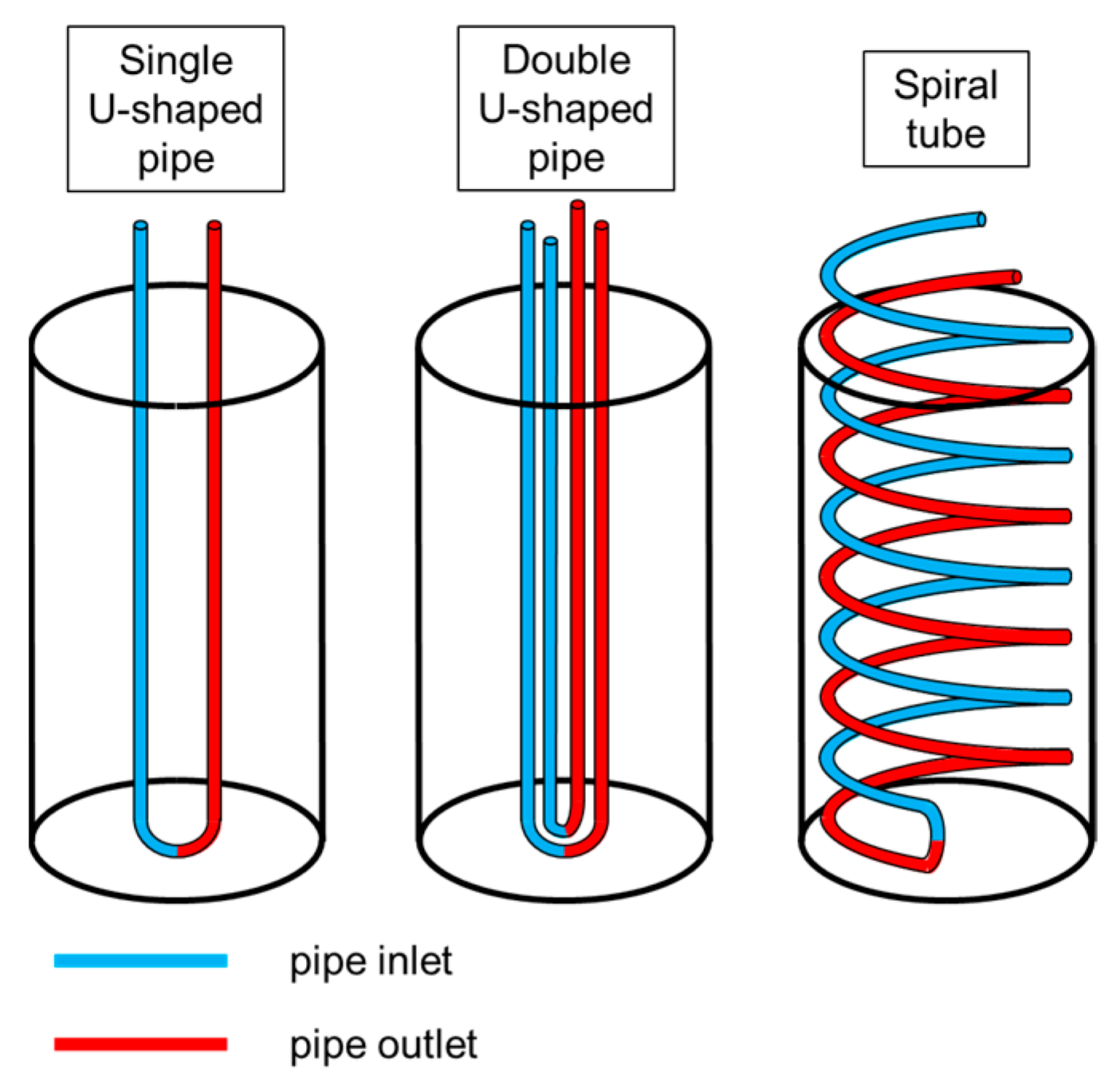
- Configurations and materials of GHEs: The design and materials used in GHEs substantially influence their performance. Optimal designs can maximize the surface contact between the ground and circulating fluid. Meanwhile, the selected materials also possess high thermal conductivity.
- Diameter and depth of borehole: The borehole depth and diameter can substantially enhance the thermal capacity and performance of GHEs, thereby improving heat transfer. However, the escalating costs of drilling must also be considered.
2. Material and Methods
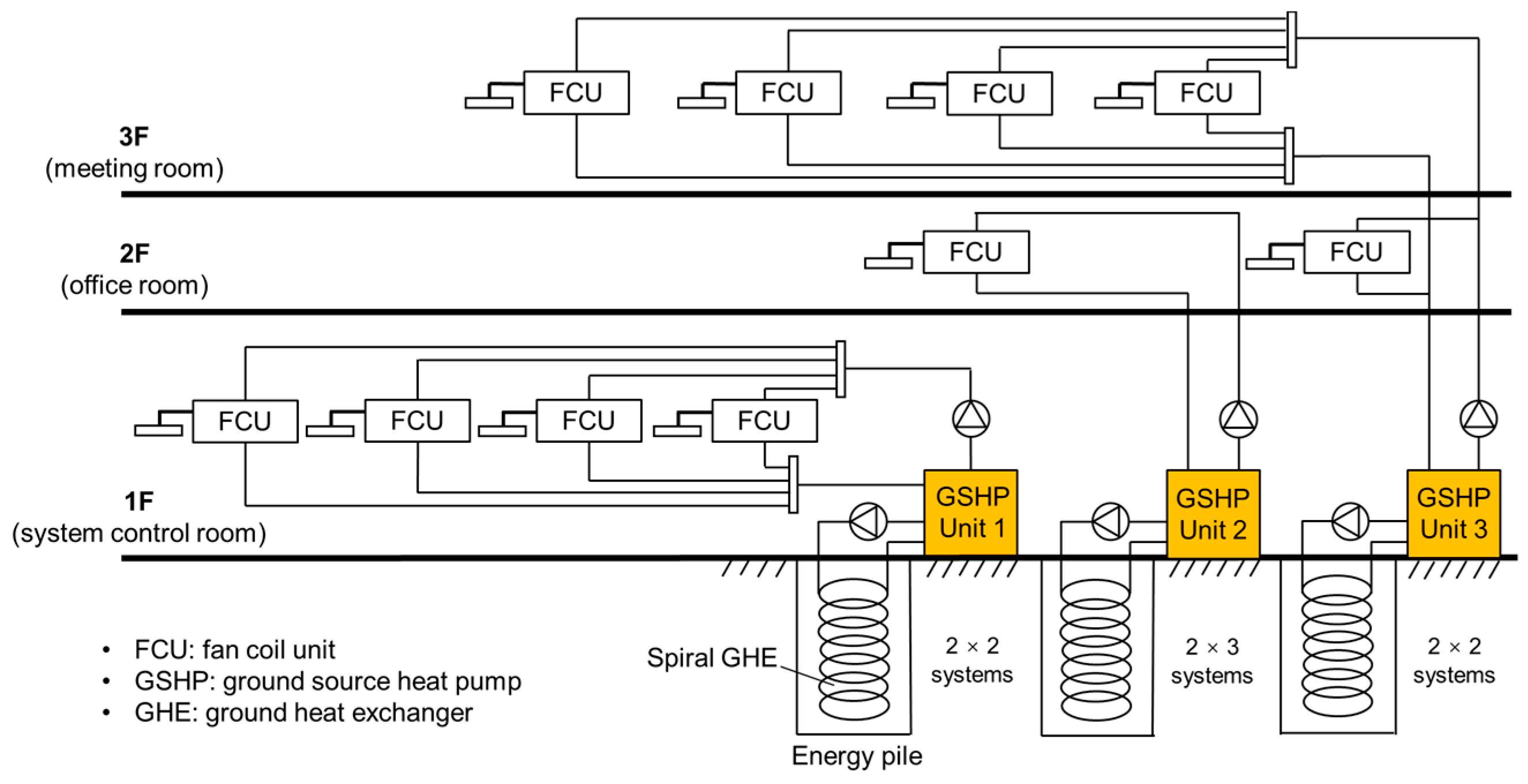
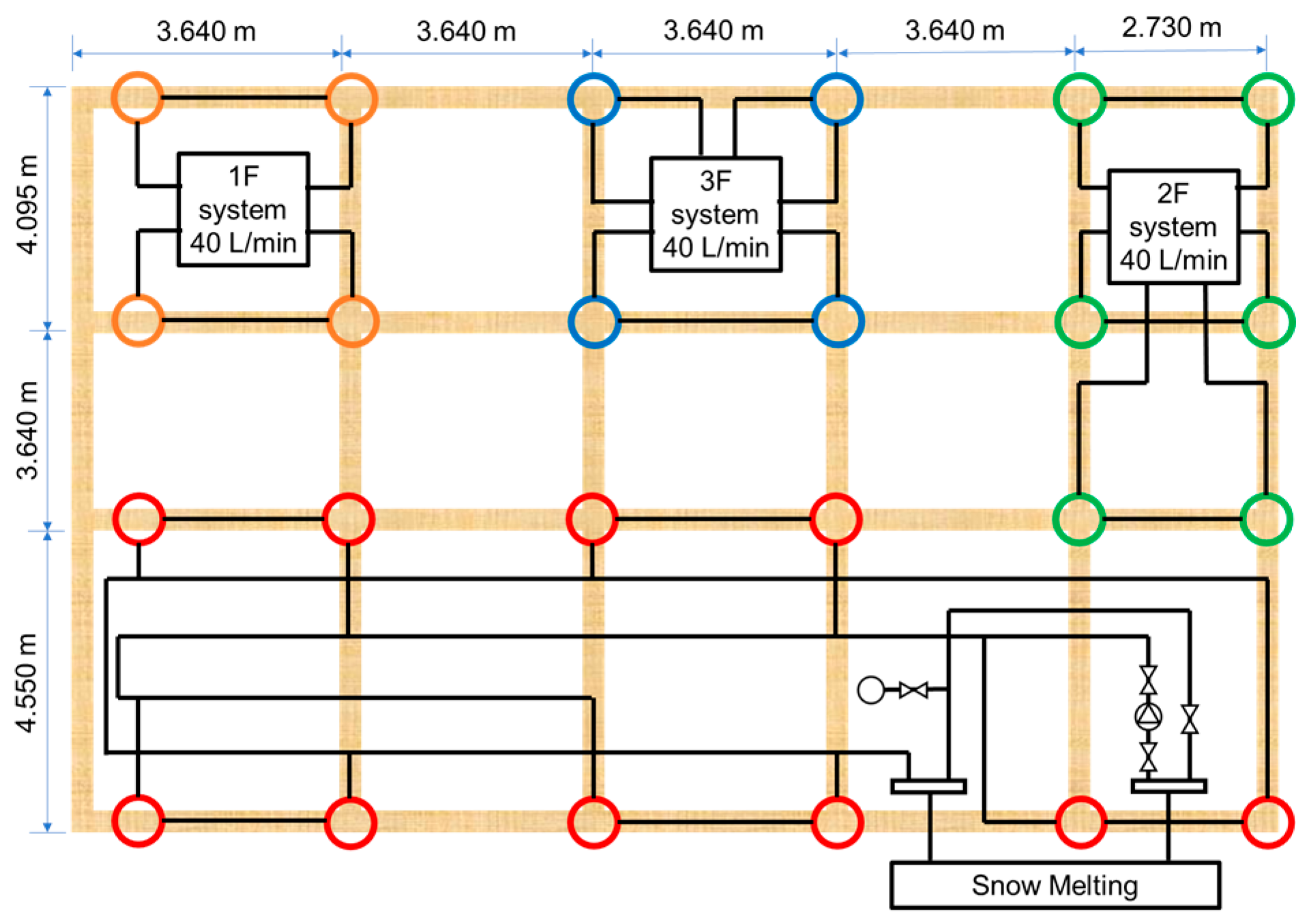
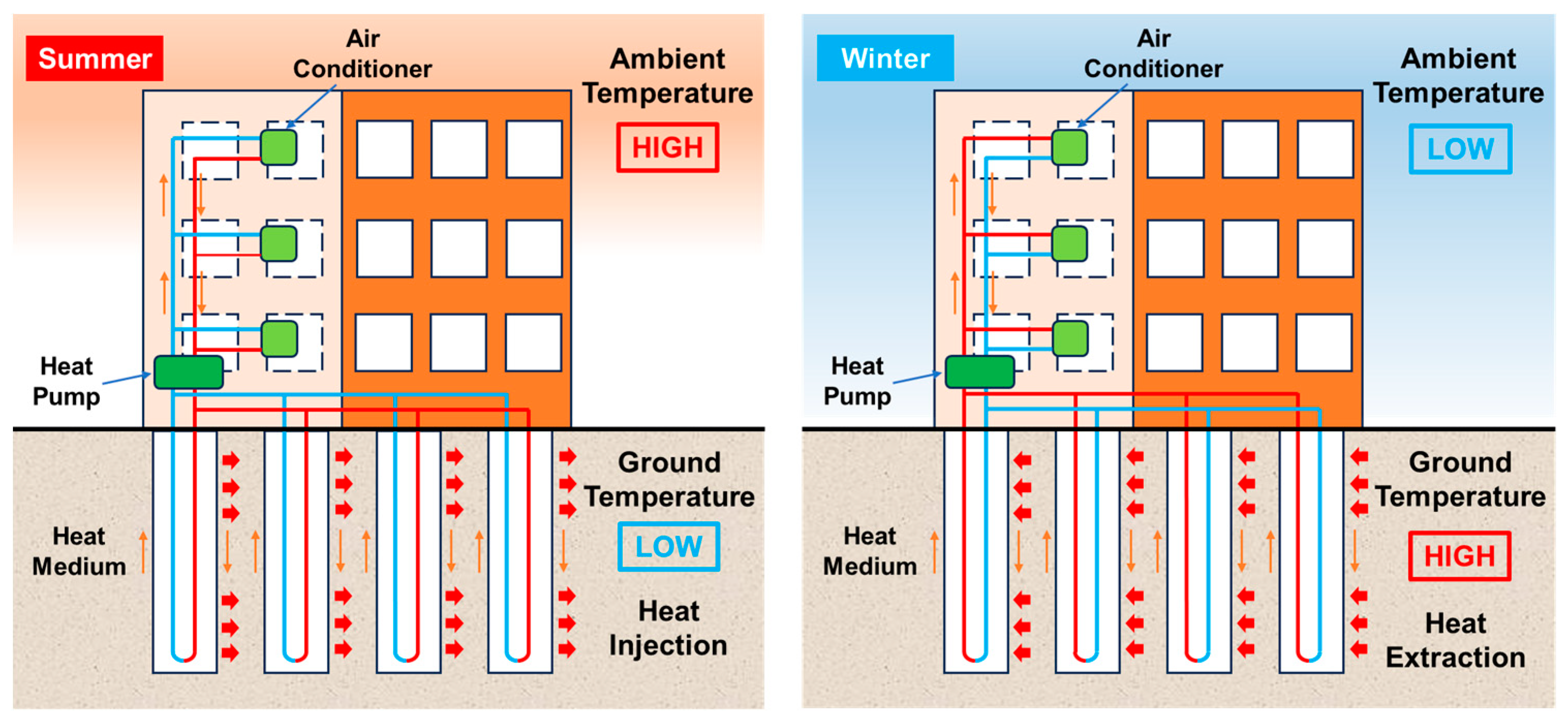
2.1. Overview of the GSHP System
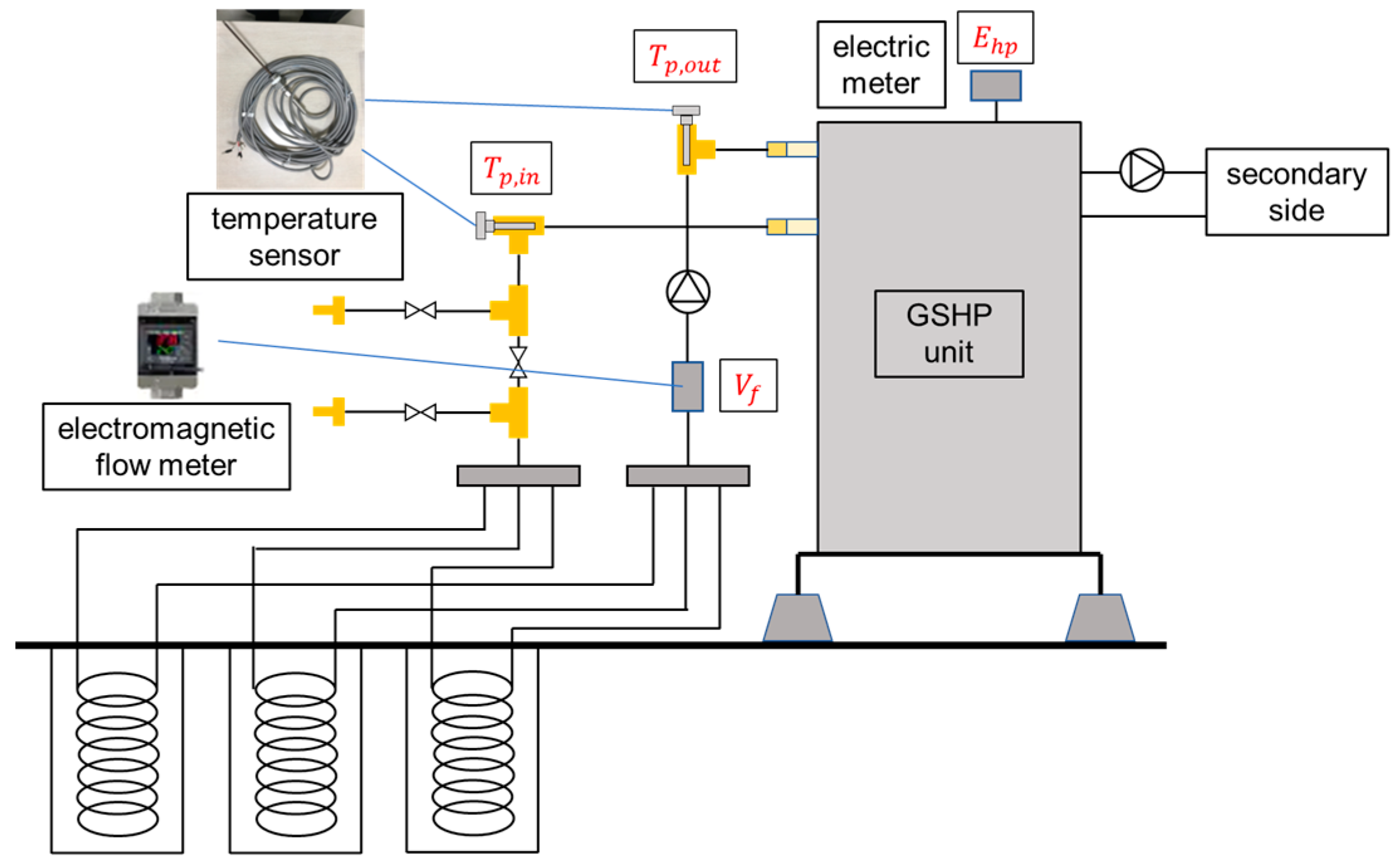
2.2. Measurement and Performance Evaluation of the GSHP System
2.3. Coefficient of Heat Extraction/Injection
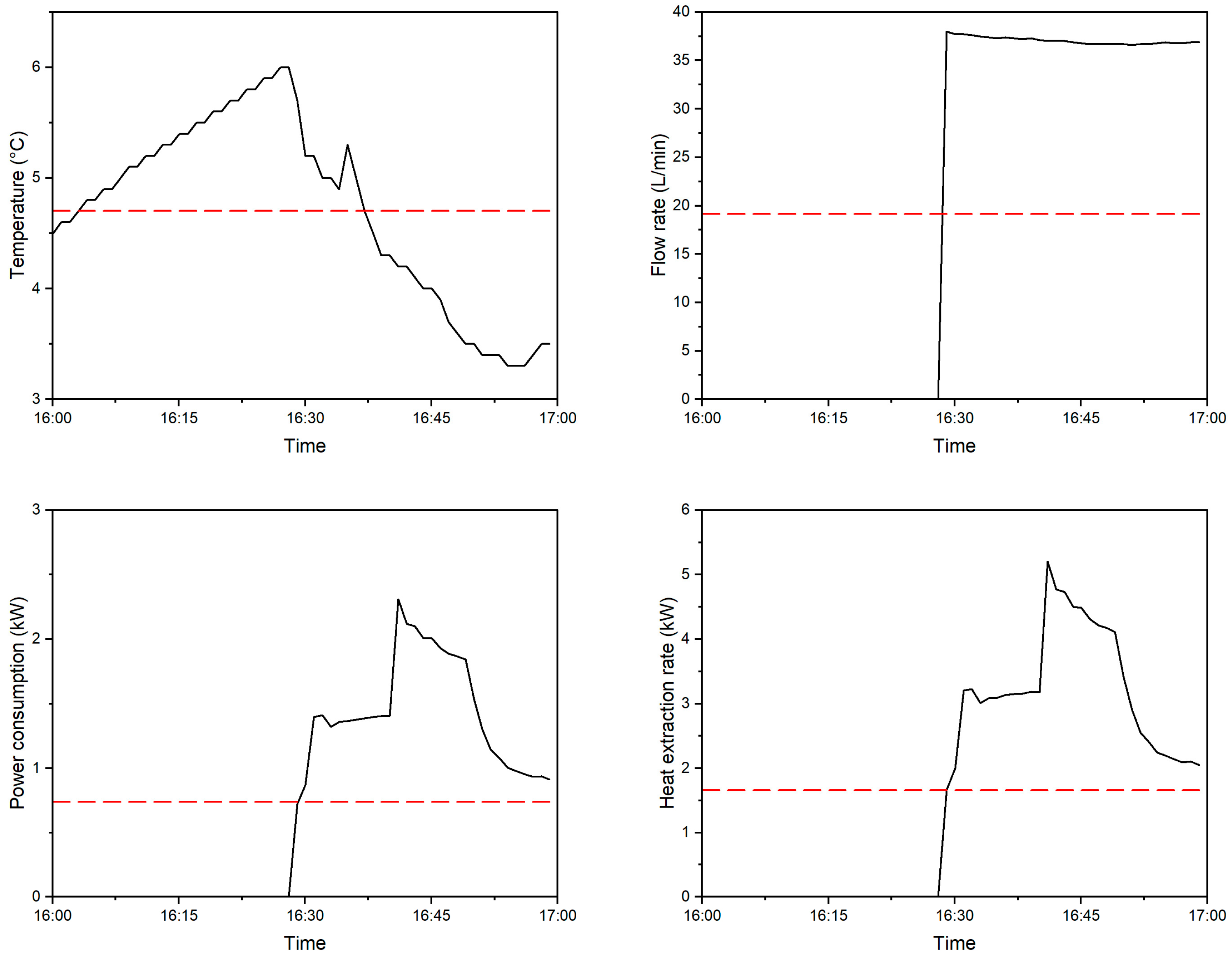
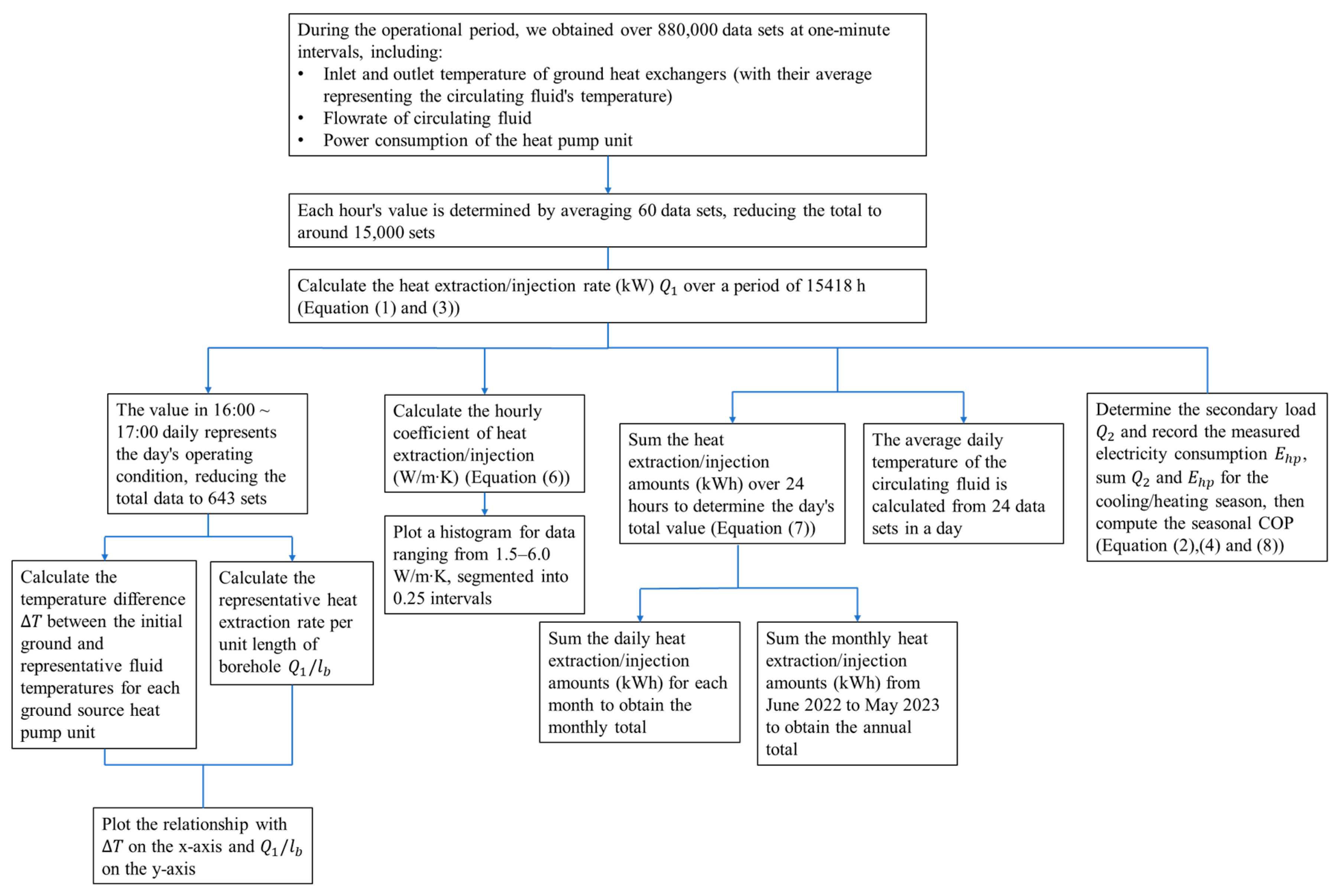
2.4. Simplification of Large Quantities of Data
2.5. Calculation of the Heat Extraction Rate and Fluid Temperature
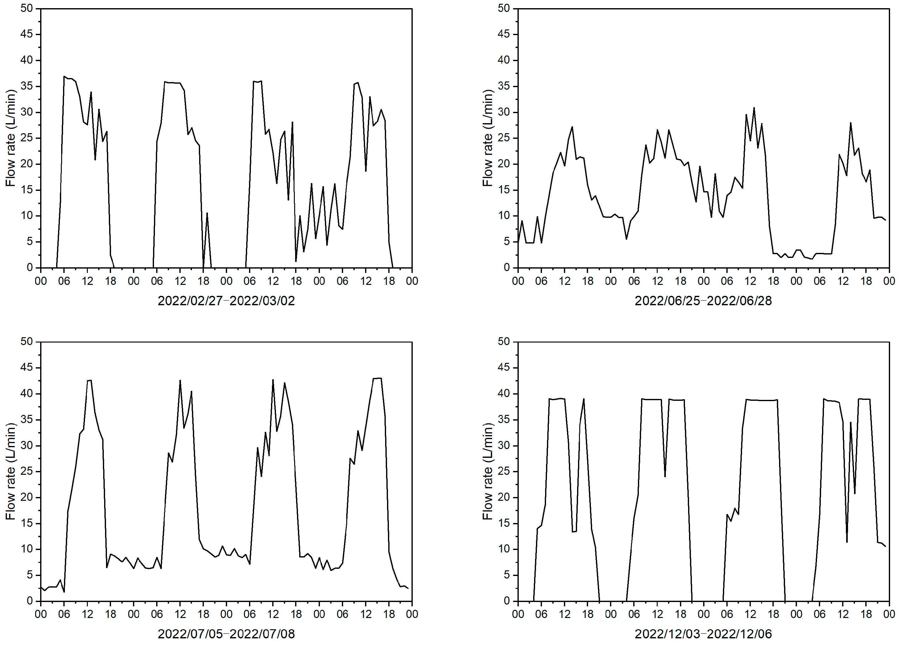
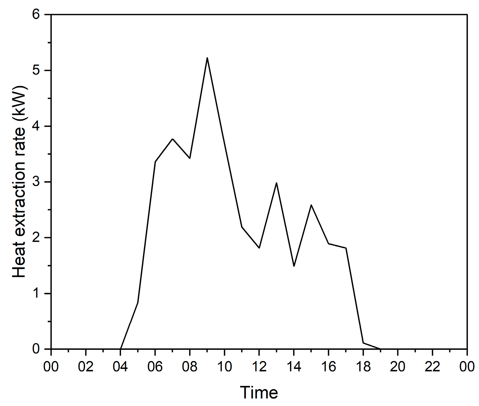
2.6. Data Visualization
2.7. Uncertainty Analysis
3. Results
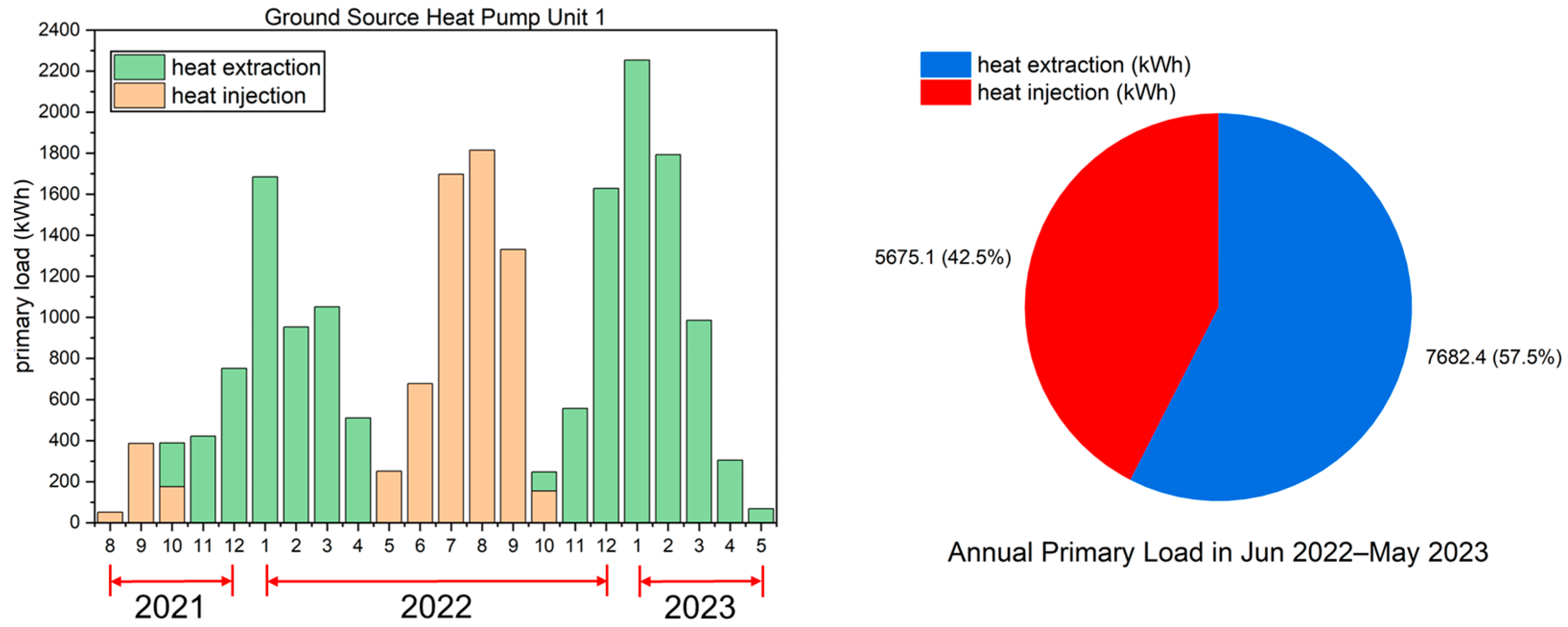
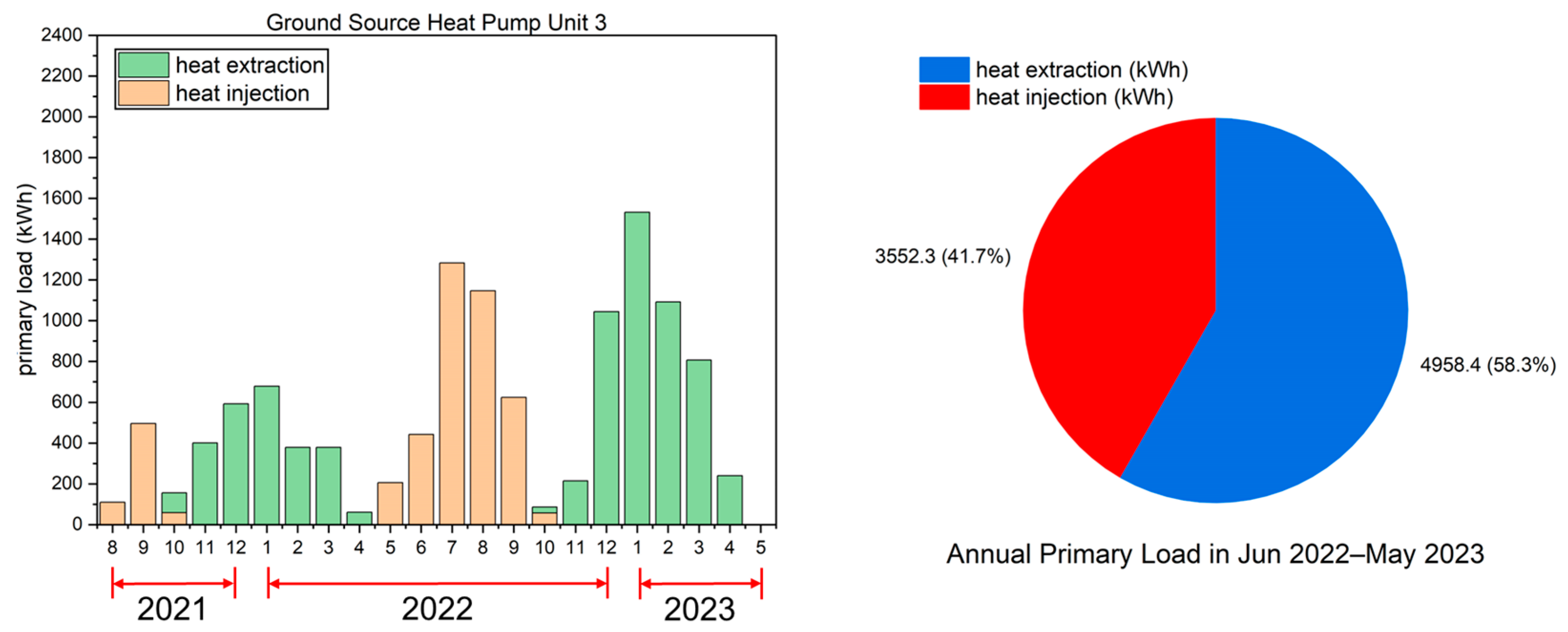
3.1. Monthly and Annual Heat Extraction/Injection Amount of the GHEs
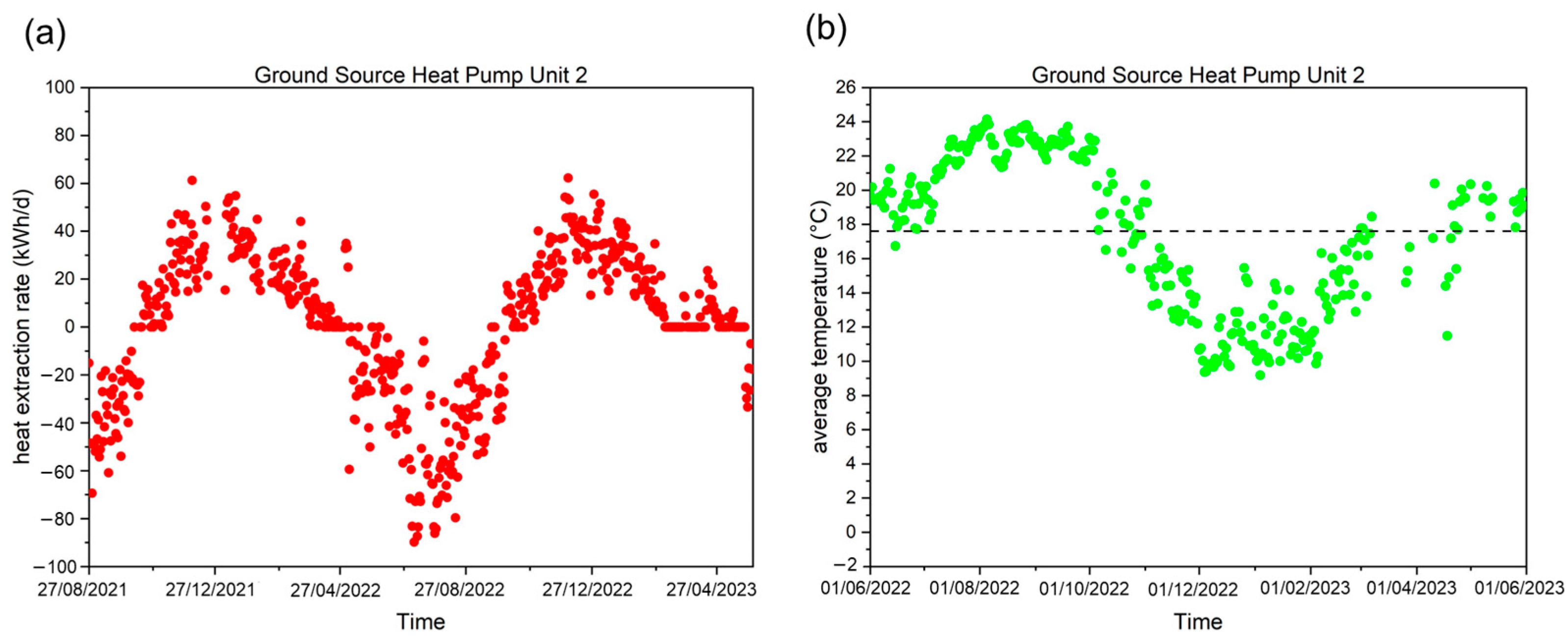
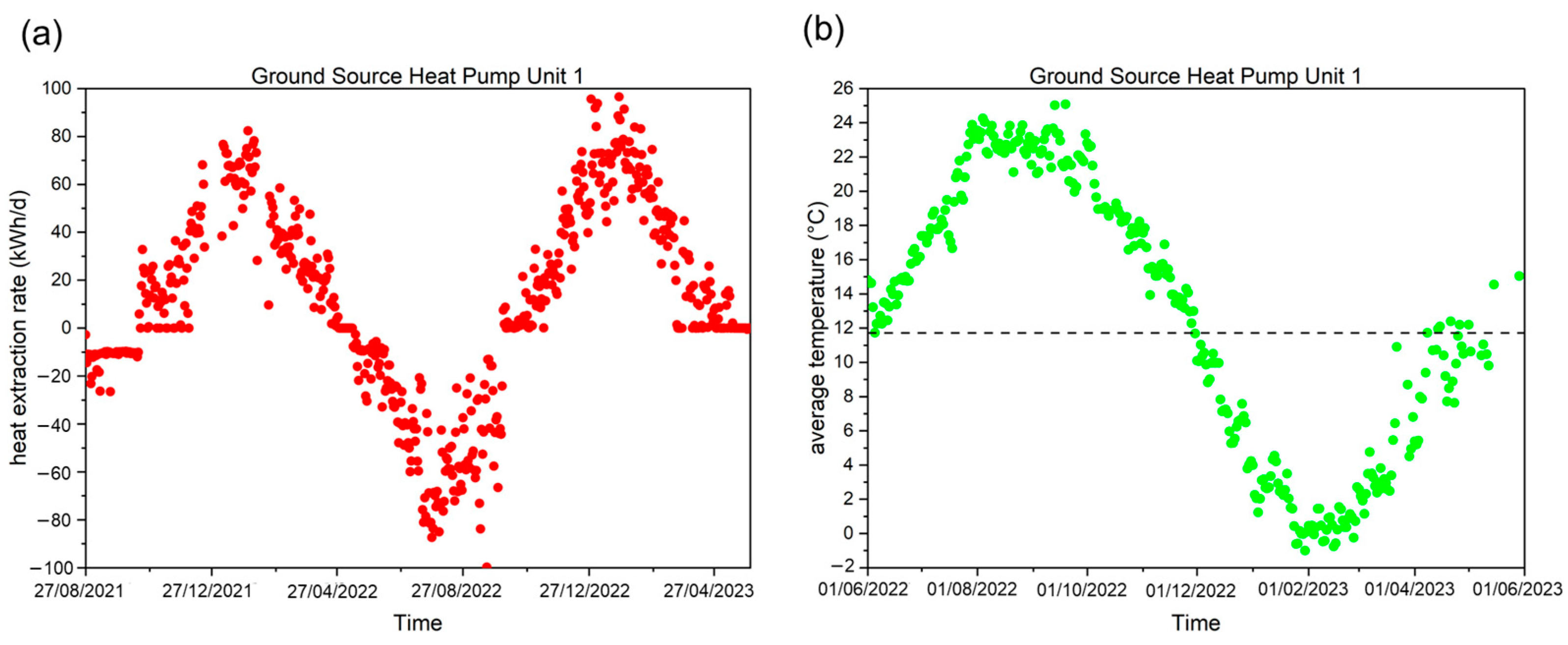
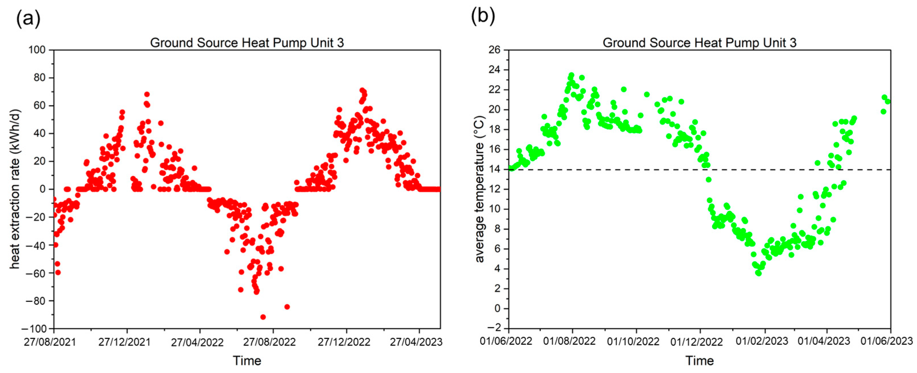
3.2. Daily Heat Extraction/Injection Rate of the GHEs and the Average Temperature of the Circulating Fluid
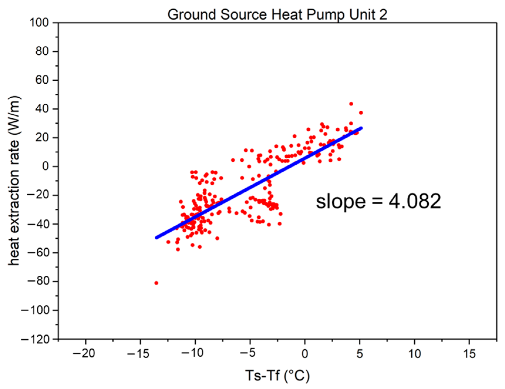
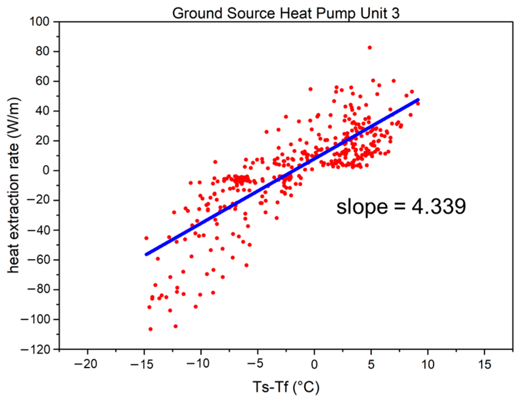
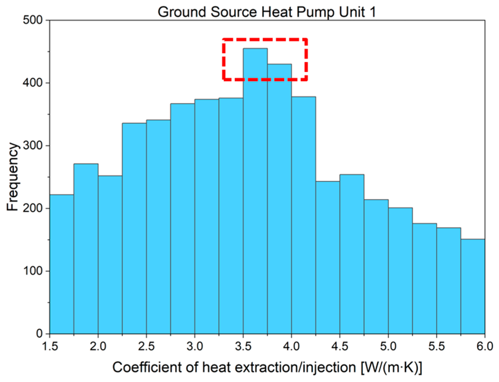
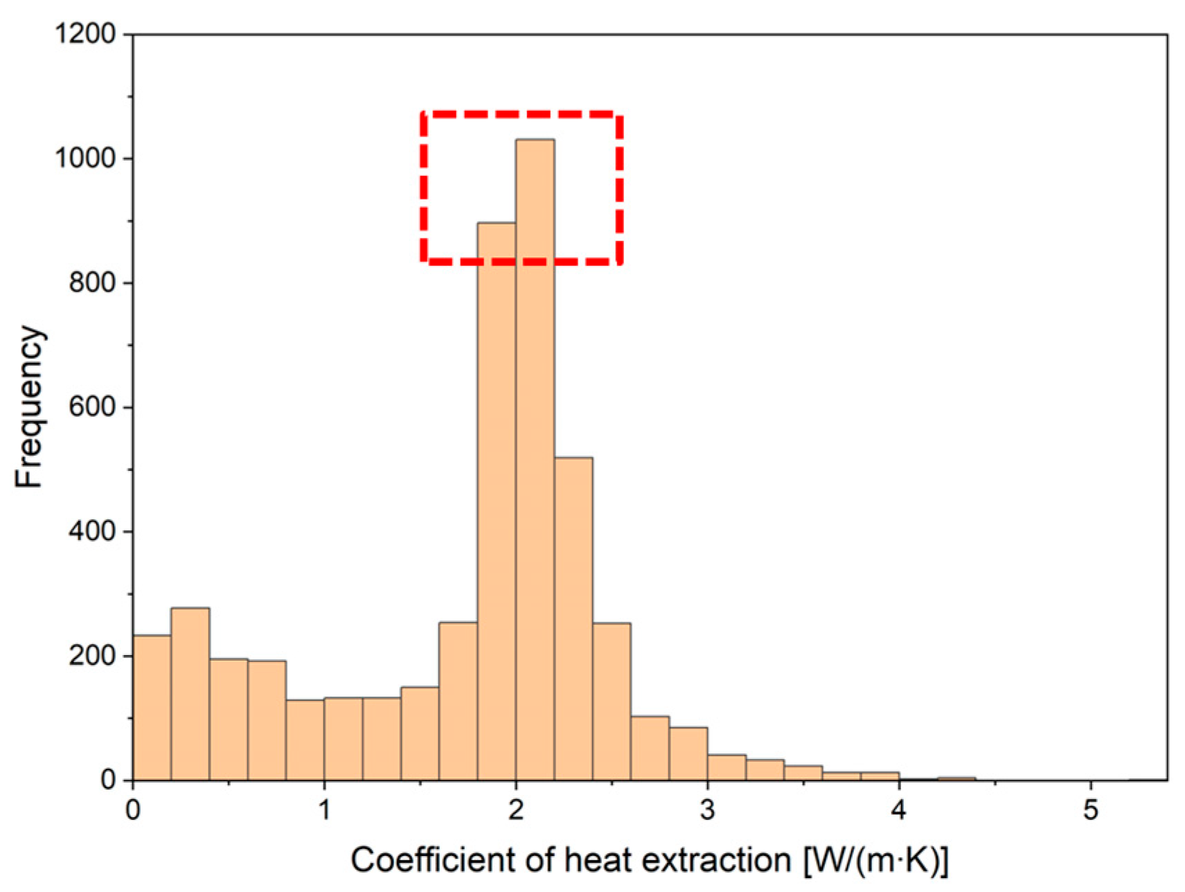
3.3. Calculation and Comparison of the Coefficient of Heat Extraction/Injection of the GHEs
3.4. Performance Evaluation of the GSHP System
3.5. Uncertainty Analysis
4. Discussion
4.1. Comparison with Traditional U-Tube GHEs
4.2. Pressure Drop of Different Types of GHE
4.3. Cooling Demands of Places in Cold Region
4.4. Study Limitations
5. Conclusions
- In contrast to the traditional U-shaped pipe GHEs, the double spiral pipe GHEs have shorter underground boreholes but larger areas for heat exchange between the ground and circulating fluid without additional drilling work, thereby reducing the initial costs of the GSHP system and promoting its future use;
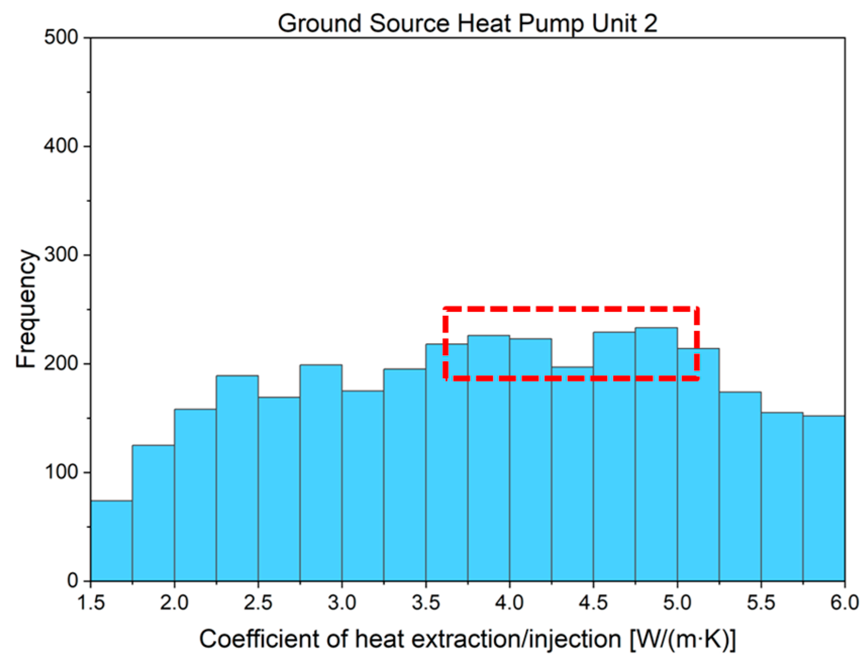
- For the most frequently used first-floor GSHP system, the temperature of the circulating fluid remained above −2 °C during winter and did not exceed 26 °C during summer, whereas the circulating fluid temperatures for other GSHP systems were within a range of 4–24 °C. Furthermore, the coefficient of heat extraction/injection of double spiral GHEs was more than 3.4 W/m∙K, with the GHEs of GSHP unit 3 even exceeding 4.3 W/m∙K. The use of histograms further confirmed these findings;
- On the second and third floors, there was an imbalance between the heat extraction and injection amounts, which may lead to a soil thermal imbalance in the long term. However, the temperature of the circulating fluid remained within an acceptable range over a period of approximately 2 years, indicating the feasibility of long-term operation and the robustness of the system to climate change;
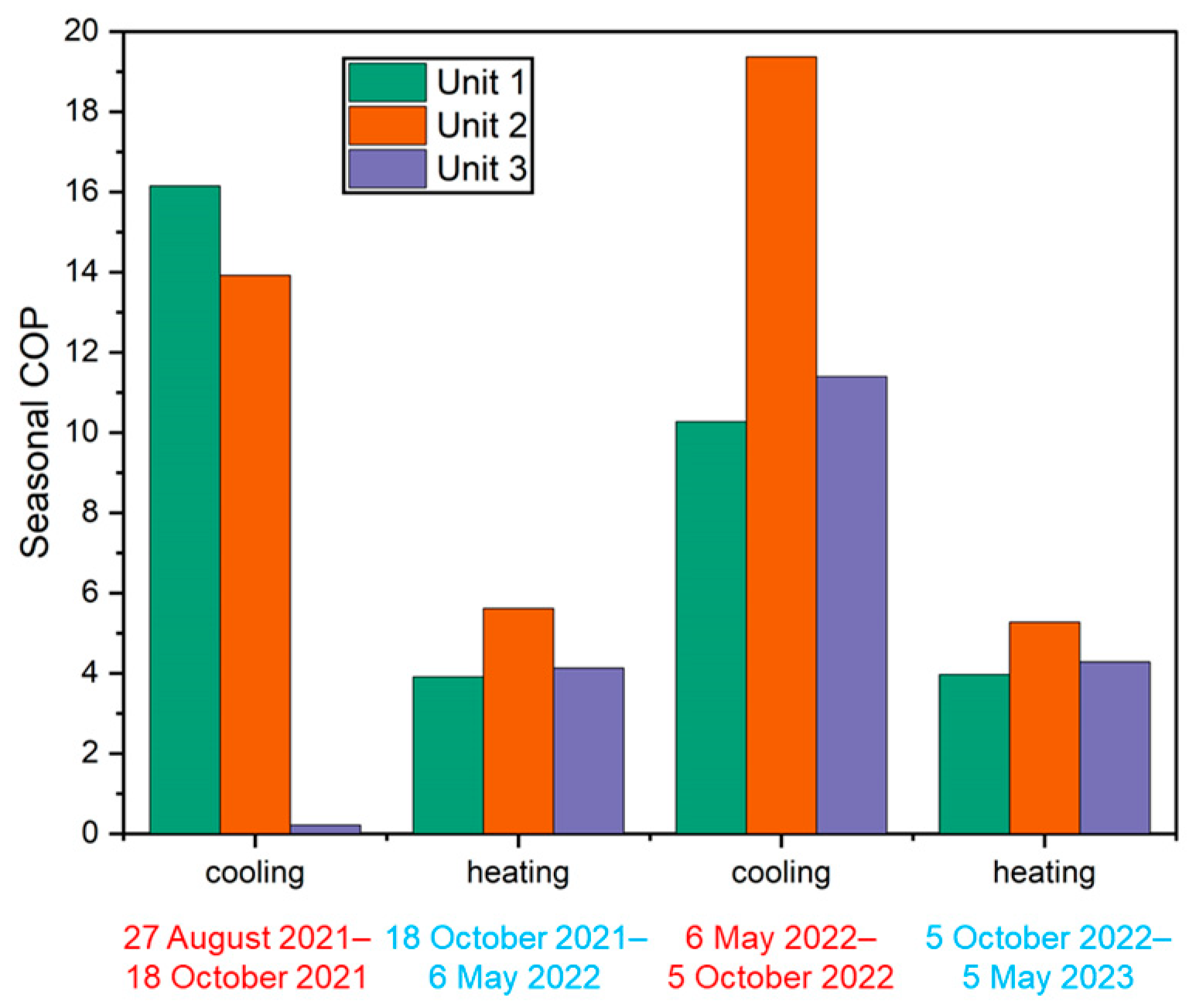
- Seasonal COP calculations indicated a high operational efficiency, with values surpassing 10 and 4 during the summer cooling and winter heating periods, respectively. These results highlight the advantages of using GSHP systems with double-spiral GHEs. After evaluating the power consumption of the circulation pump, we calculated the SCOP. Although there was a decrease compared to COP, these results are consistent with the heating COP of the GSHP system listed in Table 2;
- The pressure drop in the double spiral GHE has not been continuously measured, but verification from the on-site measurements has been carried out. Results from this verification suggest that this innovative design can effectively decrease the pressure drop and boost heat exchange efficiency;
- Considering that many ZEBs without GSHP systems in cold regions rely primarily on kerosene or gas for winter heating and rarely consider summer cooling, this study demonstrates that GSHP systems, which offer both efficient heating and cooling, are a promising choice that should be widely adopted in the future.
Author Contributions
Funding
Data Availability Statement
Acknowledgments
Conflicts of Interest
Nomenclature
| Symbols | |
| c | specific heat capacity, J/kg∙K |
| E | power consumption, kW |
| l | length/depth, m |
| q’ | coefficient of heat extraction/injection, W/m∙K |
| Q | heating/cooling load, kW |
| T | temperature, ℃ |
| U | daily primary load, kWh |
| u | uncertainty |
| v | flow rate, m3/s |
| ρ | density, kg/m3 |
| Subscripts | |
| 1 | primary side |
| 2 | secondary side |
| b | borehole of energy pile |
| f | circulating fluid |
| hp | heat pump |
| pump | circulation pump |
| p,in | pipe inlet |
| p,out | pipe outlet |
| s | soil |
| Abbreviations | |
| BHE | borehole heat exchanger |
| COP | coefficient of performance |
| DBHE | deep borehole heat exchanger |
| FCU | fan coil unit |
| GHE | ground heat exchanger |
| GSHP | ground source heat pump |
| HGHE | horizontal ground heat exchanger |
| PHC | precast high-strength concrete |
| PV | photovoltaic |
| PVC | polyvinyl chloride |
| SCOP | system coefficient of performance |
| ZEB | zero energy building |
References
- Aggarwal, V.; Meena, C.S.; Kumar, A.; Alam, T.; Kumar, A.; Ghosh, A.; Ghosh, A. Potential and future prospects of geothermal energy in space conditioning of buildings: India and worldwide review. Sustainability 2020, 12, 8428. [Google Scholar] [CrossRef]
- Sarbu, I.; Sebarchievici, C. General review of ground-source heat pump systems for heating and cooling of buildings. Energy Build. 2014, 70, 441–454. [Google Scholar] [CrossRef]
- IEA. Buildings; IEA: Paris, France, 2022; Available online: https://www.iea.org/reports/buildings (accessed on 8 August 2023).
- Nejat, P.; Jomehzadeh, F.; Taheri, M.M.; Gohari, M.; Muhd, M.Z. A global review of energy consumption, CO2 emissions and policy in the residential sector (with an overview of the top ten CO2 emitting countries). Renew Sustain. Energy Rev. 2015, 43, 843–862. [Google Scholar] [CrossRef]
- Florides, G.; Kalogirou, S. Ground heat exchangers-A review of systems, models and applications. Renew Energy 2007, 32, 2461–2478. [Google Scholar] [CrossRef]
- Lund, J.W.; Toth, A.N. Direct utilization of geothermal energy 2020 worldwide review. Geothermics 2021, 90, 101915. [Google Scholar] [CrossRef]
- Wang, D.; Lu, L.; Zhang, W.; Cui, P. Numerical and analytical analysis of groundwater influence on the pile geothermal heat exchanger with cast-in spiral coils. Appl. Energy 2015, 160, 705–714. [Google Scholar] [CrossRef]
- Zero-Emission by Low Cost Construction Method of Geothermal Heat Collection. Challenge Zero. Available online: https://www.challenge-zero.jp/en/casestudy/673 (accessed on 8 August 2023).
- Chen, C.; Shao, H.; Naumov, D.; Kong, Y.; Tu, K.; Kolditz, O. Numerical investigation on the performance, sustainability, and efficiency of the deep borehole heat exchanger system for building heating. Geotherm. Energy 2019, 7, 18. [Google Scholar] [CrossRef]
- Tang, F.; Nowamooz, H. Factors influencing the performance of shallow Borehole Heat Exchanger. Energy Convers. Manag. 2019, 181, 571–583. [Google Scholar] [CrossRef]
- Cao, J.; Bottarelli, M.; Bortoloni, M.; Pei, G. Small-scale lab analysis of the ground freezing effect on the thermal performance of a Flat-Panel ground heat exchanger. Geothermics 2018, 74, 247–254. [Google Scholar] [CrossRef]
- Zhang, J.; Lu, X.; Zhang, W.; Liu, J.; Yue, W.; Ma, F. Investigation of a Novel Deep Borehole Heat Exchanger for Building Heating and Cooling with Particular Reference to Heat Extraction and Storage. Processes 2022, 10, 888. [Google Scholar] [CrossRef]
- Congedo, P.M.; Colangelo, G.; Starace, G. CFD simulations of horizontal ground heat exchangers: A comparison among different configurations. Appl. Therm. Eng. 2012, 33, 24–32. [Google Scholar] [CrossRef]
- Zhang, G.; Cao, Z.; Liu, Y.; Chen, J. Field test and numerical simulation on the long-term thermal response of phc energy pile in layered foundation. Sensors 2021, 21, 3873. [Google Scholar] [CrossRef] [PubMed]
- Jalaluddin; Miyara, A.; Tarakka, R.; Mochtar, A.A.; Muhammad Anis, I.R. Thermal performance of shallow spiral-tube ground heat exchanger for ground-source cooling system. IOP Conf. Ser. Mater. Sci. Eng. 2019, 619, 012012. [Google Scholar] [CrossRef]
- Huang, X.; Yao, Z.; Cai, H.; Li, X.; Chen, H. Performance evaluation of coaxial borehole heat exchangers considering ground non-uniformity based on analytical solutions. Int. J. Therm. Sci. 2021, 170, 107162. [Google Scholar] [CrossRef]
- Cai, W.; Wang, F.; Chen, C.; Chen, S.; Liu, J.; Ren, Z.; Shao, H. Long-term performance evaluation for deep borehole heat exchanger array under different soil thermal properties and system layouts. Energy. 2022, 241, 122937. [Google Scholar] [CrossRef]
- Serageldin, A.A.; Sakata, Y.; Katsura, T.; Nagano, K. Thermo-hydraulic performance of the U-tube borehole heat exchanger with a novel oval cross-section: Numerical approach. Energy Convers. Manag. 2018, 177, 406–415. [Google Scholar] [CrossRef]
- Jahanbin, A. Thermal performance of the vertical ground heat exchanger with a novel elliptical single U-tube. Geothermics 2020, 86, 101804. [Google Scholar] [CrossRef]
- Majeed, S.H.; Abdul-Zahra, A.S.; Mutasher, D.G. Performance evaluation of different types of ground source heat exchangers in a hot and dry climate. Heat Transfer. 2022, 51, 5700–5722. [Google Scholar] [CrossRef]
- Li, X.; Chen, Y.; Chen, Z.; Zhao, J. Thermal performances of different types of underground heat exchangers. Energy Build. 2006, 38, 543–547. [Google Scholar] [CrossRef]
- Kerme, E.D.; Fung, A.S. Heat transfer analysis of single and double U-tube borehole heat exchanger with two independent circuits. J. Energy Storage 2021, 43, 103141. [Google Scholar] [CrossRef]
- Luo, J.; Rohn, J.; Bayer, M.; Priess, A. Thermal performance and economic evaluation of double U-tube borehole heat exchanger with three different borehole diameters. Energy Build. 2013, 67, 217–224. [Google Scholar] [CrossRef]
- Kim, J.W.; Kim, Y.M.; Ko, Y.J.; Chen, Q.; Xin, C.; Oh, S.J. Study on an advanced borehole heat exchanger for ground source heat pump operating in volcanic island: Case study of Jeju island, South Korea. Front. Built. Environ. 2022, 8, 1061760. [Google Scholar] [CrossRef]
- Zou, H.; Pei, P.; Wang, C.; Hao, D. A numerical study on heat transfer performances of horizontal ground heat exchangers in ground-source heat pumps. PLoS ONE 2021, 6, e0250583. [Google Scholar] [CrossRef] [PubMed]
- Dehghan, B.B. Experimental and computational investigation of the spiral ground heat exchangers for ground source heat pump applications. Appl. Therm. Eng. 2017, 121, 908–921. [Google Scholar] [CrossRef]
- Li, B.; Zheng, M.; Shahrestani, M.; Zhang, S. Driving factors of the thermal efficiency of ground source heat pump systems with vertical boreholes in Chongqing by experiments. J. Build. Eng. 2020, 28, 101049. [Google Scholar] [CrossRef]
- Walch, A.; Li, X.; Chambers, J.; Mohajeri, N.; Yilmaz, S.; Patel, M.; Scartezzini, J.L. Shallow geothermal energy potential for heating and cooling of buildings with regeneration under climate change scenarios. Energy 2022, 244, 123086. [Google Scholar] [CrossRef]
- Guo, L.; Zhang, J.; Li, Y.; McLennan, J.; Zhang, Y.; Jiang, H. Experimental and numerical investigation of the influence of groundwater flow on the borehole heat exchanger performance: A case study from Tangshan, China. Energy Build. 2021, 248, 111199. [Google Scholar] [CrossRef]
- Tu, S.; Yang, X.; Zhou, X.; Luo, M.; Zhang, X. Experimenting and modeling thermal performance of ground heat exchanger under freezing soil conditions. Sustainability 2019, 11, 5738. [Google Scholar] [CrossRef]
- Yang, K.; Katsura, T.; Nagasaka, S.; Nagano, K. Development and application of a new calculation method for double spiral ground heat exchangers. Energy Build. 2023, 291, 113144. [Google Scholar] [CrossRef]
- Katsura, T.; Nagano, K.; Nakamura, Y. A study on design method for the ground heat exchanger’s specification of ground source heat pump system. J. Environ. Eng. 2011, 76, 59Y66. [Google Scholar] [CrossRef]
- Products/INOAC Housing & Construction Materials Co., Ltd. Available online: https://www.inoac-juukan.co.jp/en/product/ (accessed on 27 September 2023).


| Building | Energy Saving Technologies |
|---|---|
| Location: Sapporo, Japan | Heat recovery ventilation system |
| Floor area: 650.85 m2 | High thermal insulation |
| Number of floors: Three | Photovoltaic (PV) system |
| Operation time: July 2021–present | Radiant air conditioning system |
| Structure: Wooden | Ground source heat pump (GSHP) system |
| Description | Unit | Value |
|---|---|---|
| Ground source heat pump unit | ||
| Heating capacity | kW | 10.0 |
| Heating Coefficient of Performance (COP) | 3.7 | |
| Cooling capacity | kW | 10.0 |
| Cooling Coefficient of Performance (COP) | 3.2 | |
| Thermal pile | ||
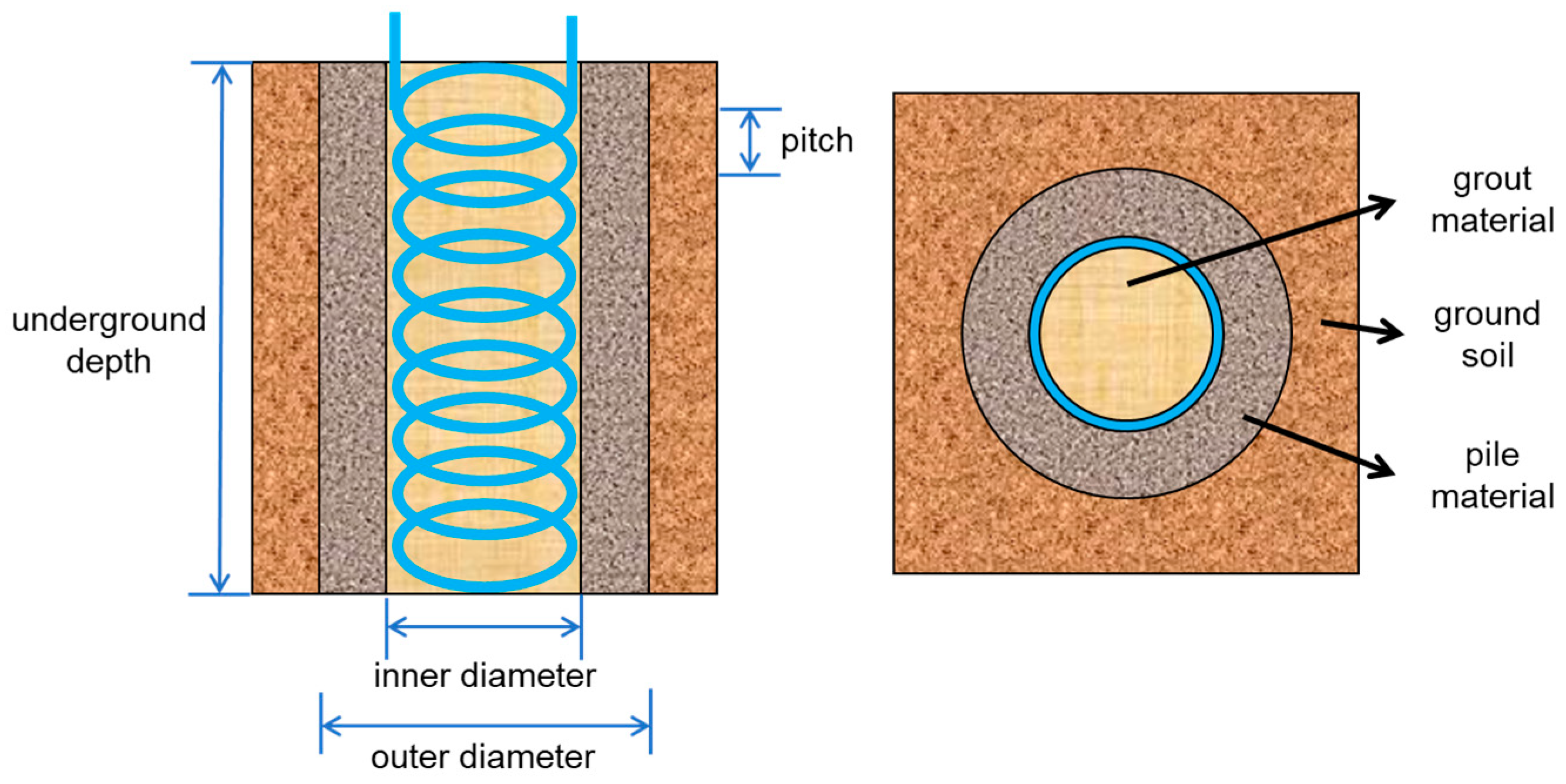
| Depth | m | 20 |
| Outer diameter | m | 0.6 |
| Inner diameter | m | 0.4 |
| Grouting material (cement and soil) | ||
| Thermal conductivity | W/m∙K | 0.6 |
| Specific heat capacity | kJ/kg∙K | 0.9 |
| Density | kg/m3 | 2100 |
| Pile material (concrete) | ||
| Thermal conductivity | W/m∙K | 2.0 |
| Specific heat capacity | kJ/kg∙K | 0.95 |
| Density | kg/m3 | 2500 |
| Spiral tube ground heat exchangers (GHEs) | ||
| Outer tube diameter | m | 0.032 |
| Inner tube diameter | m | 0.026 |
| Spiral distance | m | 0.25 |
| Thermal conductivity of pipe material | W/m∙K | 0.38 |
| Length of spiral pipe | m | 94.63 |
| Circulating fluid: 40% ethylene glycol solution | ||
| Soil | ||
| Specific heat capacity | kJ/kg∙K | 2 |
| Density | kg/m3 | 1500 |
| Undisturbed ground temperature | °C | 12 |
| Conductivity | W/m∙K | 1.846 |
| Circulation pump | ||
| Rated flowrate | L/min | 40 |
| Rated power consumption | kW | 0.4 |
| Parameter | Unit | Uncertainty |
|---|---|---|
| Pipe inlet temperature Tp,in | °C | (0.30 + 0.005|Tp,in|) |
| Pipe outlet temperature Tp,out | °C | (0.30 + 0.005|Tp,out|) |
| Flowrate of circulating fluid vf | L/min | 0.005 vf |
| No. | Period | Pipe Inlet Temperature | Pipe Outlet Temperature | Fluid Flowrate | ||
|---|---|---|---|---|---|---|
| 1 | 15:00–16:00 | 26.15 °C | 24.49 °C | 43.86 L/min | 4.140 | 0.756 |
| 2 | 16:00–17:00 | 25.98 °C | 24.31 °C | 43.84 L/min | 4.253 | 0.764 |
| 3 | 17:00–18:00 | 25.87 °C | 24.23 °C | 43.82 L/min | 4.175 | 0.769 |
| 4 | 18:00–19:00 | 25.72 °C | 24.15 °C | 43.81 L/min | 4.039 | 0.774 |
| Description | Value |
|---|---|
| Location | Sapporo, Japan |
| Measurement period | October 2005–May 2008 |
| Type of ground heat exchanger | Borehole single U-tube |
| Borehole vertical length | 100 m |
| Circulating fluid | 40% ethylene glycol solution |
| Rated heat extraction | 4.5 kW |
| Rated heating output | 6.2 kW |
| Rated power consumption | 1.7 kW |
| Temperature of undisturbed layer | 10.4 °C |
Disclaimer/Publisher’s Note: The statements, opinions and data contained in all publications are solely those of the individual author(s) and contributor(s) and not of MDPI and/or the editor(s). MDPI and/or the editor(s) disclaim responsibility for any injury to people or property resulting from any ideas, methods, instructions or products referred to in the content. |
© 2023 by the authors. Licensee MDPI, Basel, Switzerland. This article is an open access article distributed under the terms and conditions of the Creative Commons Attribution (CC BY) license (https://creativecommons.org/licenses/by/4.0/).
Share and Cite
Yang, K.; Katsura, T.; Nagasaka, S.; Nagano, K. Analyzing the Performance of Double Spiral Tube Ground Heat Exchangers in a Zero-Energy Building Using Measurement Data. Energies 2023, 16, 6964. https://doi.org/10.3390/en16196964
Yang K, Katsura T, Nagasaka S, Nagano K. Analyzing the Performance of Double Spiral Tube Ground Heat Exchangers in a Zero-Energy Building Using Measurement Data. Energies. 2023; 16(19):6964. https://doi.org/10.3390/en16196964
Chicago/Turabian StyleYang, Kunning, Takao Katsura, Shigeyuki Nagasaka, and Katsunori Nagano. 2023. "Analyzing the Performance of Double Spiral Tube Ground Heat Exchangers in a Zero-Energy Building Using Measurement Data" Energies 16, no. 19: 6964. https://doi.org/10.3390/en16196964
APA StyleYang, K., Katsura, T., Nagasaka, S., & Nagano, K. (2023). Analyzing the Performance of Double Spiral Tube Ground Heat Exchangers in a Zero-Energy Building Using Measurement Data. Energies, 16(19), 6964. https://doi.org/10.3390/en16196964