3.1. Effect of Al2O3 Layer Thickness on the Passivation and Electrical Performance
The Al
2O
3 film is the first film to be prepared in the Al
2O
3/SiN
x rear-side stacked passivation layer of polycrystalline PERC solar cells. The raw materials for preparing Al
2O
3 are TMA, N
2O and Ar. Ar is a kind of inert gas that does not participate in chemical reactions and mainly plays a blowing role. TMA reacts with N
2O in the reaction chamber to generate Al
2O
3 film, which is deposited on the silicon wafer substrate. To examine the influence of the Al
2O
3 layer thickness on minority carrier lifetime and electrical performance, a series of wafer samples with different Al
2O
3 layer thicknesses were fabricated by adjusting the TMA flow rate and maintaining the N
2O flow rate.
Table 2 shows the correspondence between the TMA flow rate and Al
2O
3 layer thickness. It can be seen that by increasing the TMA flow rate within a certain range, which was from 300 to 760 mg/min, the Al
2O
3 layer thickness increased continuously and showed a linear relationship with TMA flow rate.
To investigate the effect of Al
2O
3 thickness on the minority carrier lifetime of PERC before and after sintering, we continue to deposit a layer of SiN
x film on the top of the Al
2O
3 film. The SiN
x layer thickness and the refractive index in this section were set to 110 nm and 2.05, respectively.
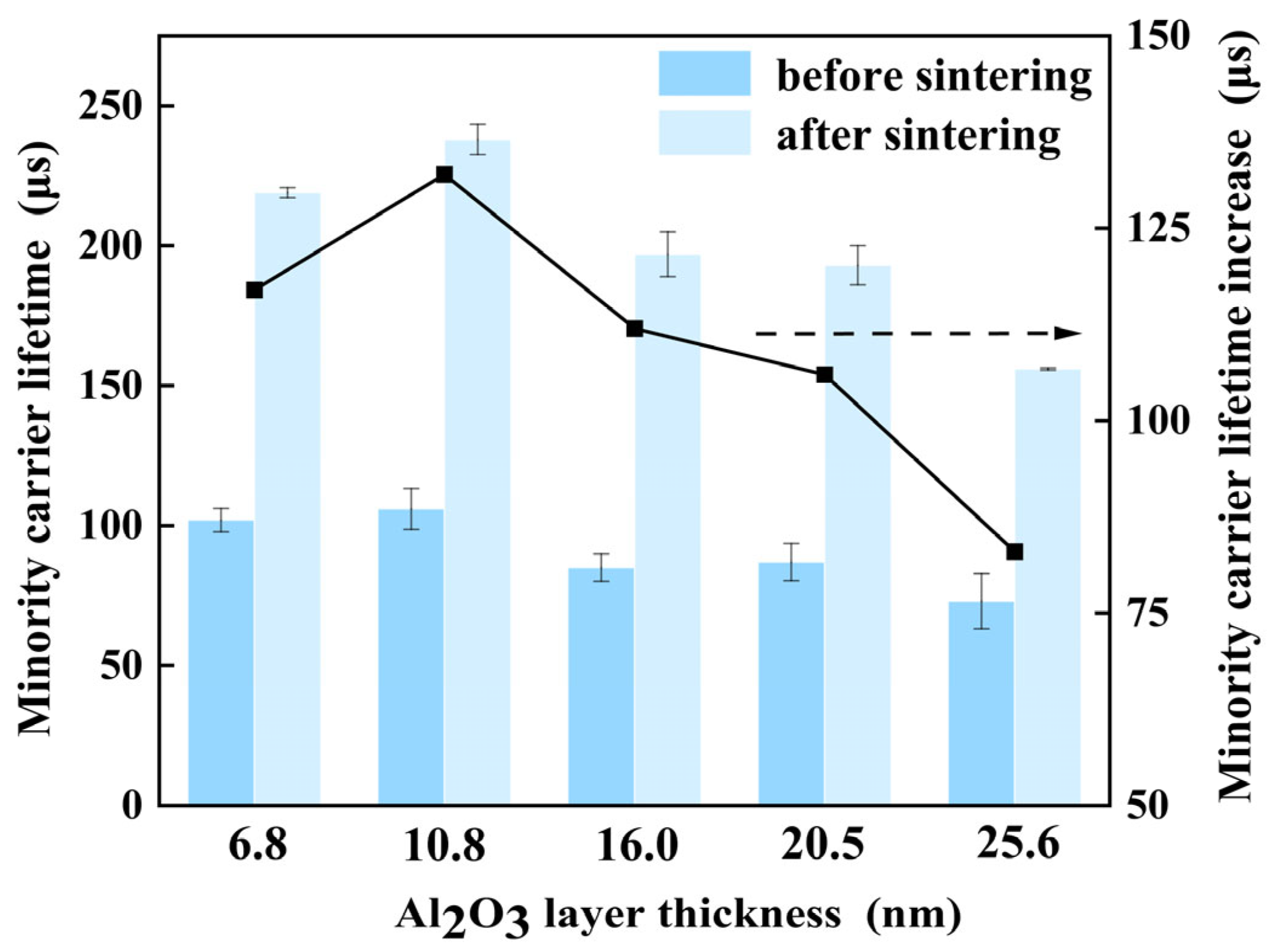
Figure 2 shows the minority carrier lifetime before and after sintering of the polycrystalline PERC solar cell with different Al
2O
3 layer thicknesses. The difference in minority carrier lifetime before and after sintering was significant at the same thickness. The minority carrier lifetime was in the range of 73~106 μs before sintering and was in the range of 156~238 μs after sintering. The sintering process resulted in an increase in minority carrier lifetime and the increment of that was from 83 to 132 μs under different Al
2O
3 layer thicknesses. When the film thickness was 10.8 nm, the increase in minority carrier lifetime was the largest, which was 132 μs.
The reason to explain the occurrence of the above phenomenon is that hydrogen atoms released from the Al
2O
3 layer can easily cross the Al
2O
3 layer and then enter into the silicon substrate to passivate the hanging bonds on the silicon surface. However, as the thickness of the Al
2O
3 layer was larger than 10.8 nm, the passivation effect would be unsatisfactory, as the diffusion of hydrogen atoms to the silicon bulk is blocked. At the same time, high-temperature sintering would promote the occurrence of this process. The above conclusions are consistent with the previous results [
16,
17]. Therefore, an appropriate thickness of Al
2O
3 film is necessary to achieve an excellent passivation effect. Based on comprehensive analysis, a TMA flow rate of 420 mg/min and Al
2O
3 film thickness of 10.8 nm are the most suitable parameters.
Table 3 shows the electrical performance parameters of the polycrystalline PERC solar cells with different Al
2O
3 layer thicknesses. As can be seen from the table, the conversion efficiency showed a trend of increasing firstly and then decreasing with the thickness of Al
2O
3 increasing. The best performance of the solar cells was achieved when the film thickness was 10.8 nm. Meanwhile, the highest efficiency was 19.48%, corresponding V
oc was 0.6519 V, I
sc was 9.2053 A and FF was 79.74. The overall trend is consistent with
Figure 2, which indicates that the change in electrical performance of polycrystalline PERC cells with different Al
2O
3 layer thicknesses is mainly caused by the difference in the effect of backside passivation. Therefore, for polycrystalline PERC, the passivation effect and electrical performance were optimal when the thickness of the Al
2O
3 layer was 10.8 nm.
3.2. Effect of SiNx Layer Thickness on the Passivation and Electrical Performance
In this section, the substrate was first deposited with an Al
2O
3 layer of the optimum thickness of 10.8 nm, which was learned through
Section 3.1. Then, the wafer substrate was transported to the process chamber via a conveyor belt on MAiA equipment to complete the SiN
x deposition using the PECVD method. From
Table 4 we can see that different SiN
x layer thicknesses of 65, 80, 100, 120 and 150 nm can be obtained by changing the conveyor belt speed from 180 to 460 cm/min and maintaining constant process parameters such as SiH
4 and NH
3 flow ratio, microwave power, temperature and deposition rate in the SiN
x process chamber. Due to the constant silane ratio, the refractive index remained unchanged and was still set to 2.05. From
Table 4, we can see that the faster the conveyor belt speed, the thinner the SiN
x layer.
Although a single layer of Al
2O
3 can already provide a good passivation effect, its thermal stability is poor. Covering a layer of SiN
x can not only protect the Al
2O
3 layer to improve the thermal stability but also increase the thickness of the back surface layer and reduce light transmission. Similar to Al
2O
3, the thickness of SiN
x also affects the efficiency of the polycrystalline PERC solar cells.
Figure 3 shows the minority carrier lifetime before and after sintering with different SiN
x layer thicknesses. It can be seen from the figure that there were some differences in minority carrier lifetime before sintering with different SiN
x layer thicknesses. Before sintering, minority carrier lifetimes of the wafers were between 60 μs and 79 μs, while after sintering, the minority carrier lifetime of the wafers improved to 153~219 μs rapidly, which was more than twice as much as the cells without sintering. When the SiN
x film thickness was 120 nm, the passivation effect was optimal.
To a certain extent, the thicker the rear SiNx, the better the passivation effect. At the same time, more photons would be reflected to the p-n junction if the photons were to reach the P-type silicon substrate and owing to that, more photon-generated carriers would be produced. However, if the SiNx layer were to be too thick, the probability of the photon being reflected to p-n would decrease because the thicker SiNx layer would have more internal defects within its body. Furthermore, this would result in a decrease in the efficiency of polycrystalline PERC solar cells. On the other hand, if the SiNx layer were to be too thin, the Al paste would locally fire through the SiNx layer during sintering. Then, additional parasitic Al contacts would be formed which would increase contact recombination, resulting in a decrease in the conversion efficiency of solar cells. As a consequence, an appropriate thickness of SiNx film is also necessary to achieve an excellent passivation effect. Based on comprehensive analysis, a conveyor belt speed of 220 cm/min and SiNx film thickness of 120 nm are the most suitable parameters.
Table 5 shows the electrical performance parameters of polycrystalline PERC solar cells with different SiN
x layer thicknesses. The conversion efficiency showed a trend of increase before decrease, which was consistent with
Figure 3. Therefore, for PERC with Al
2O
3/SiN
x rear-side stacked passivation layers, the optimal thickness of SiN
x was 120 nm. At this point, the conversion efficiency was 19.34%, and the corresponding V
oc, I
sc and FF were 0.6497 V, 9.2547 A and 79.02, respectively.
3.3. Effect of Refractive Index on the Passivation and Electrical Performance
In this section, the SiN
x and Al
2O
3 layer thicknesses on the rear side of PERC were kept constant at 120 nm and 10.8 nm, respectively. By adjusting the flow ratio of SiH
4 and NH
3, SiN
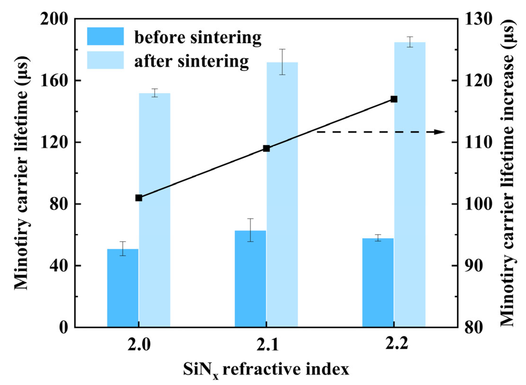
x layers with different refractive indices were prepared, which were 2.0, 2.1 and 2.2. From
Figure 4, we can see that the minority carrier lifetime increased with the increase in the refractive index. Before sintering, the minority carrier lifetime was between 51 and 63 μs. After sintering, the minority carrier lifetime increased rapidly and was almost three times that, which was between 152 and 185 μs. The maximum value of the minority carrier lifetime after sintering reached 185 μs at a SiN
x refractive index of 2.2.
With the SiN
x layer thickness remaining constant, increasing the flow ratio of SiH
4 and NH
3 would increase the refractive index of SiN
x, which would increase the Si content in the SiN
x layer. Furthermore, the concentration of the Si-H bond was also found to increase. As is known to all, Si-rich SiN
x films have a higher hydrogen content, thus increasing the number of Si-H bonding, resulting in improving the passivation effect [
18,
19,
20]. However, the refractive index cannot be too large because the greater the difference between the refractive index of the SiN
x and air, the higher the reflectivity will be, which was found in previous studies [
21].
Table 6 shows the electrical performance parameters of the polycrystalline PERC solar cells with different SiN
x refractive indices. With the increase of the SiN
x refractive index from 2.0 to 2.2, the conversion efficiency was changed from 18.73% to 19.20%. At the same time, V
oc increased from 0.6408 V to 0.6470 V, I
sc increased from 9.0769 A to 9.2100 A and FF increased from 79.10 to 79.18. The electrical performance parameters at the 2.2 refractive index are the most excellent. On the one hand, an increase in the refractive index of the backside SiN
x would improve the passivation effect. On the other hand, a higher refractive index would reduce the light transmission and increase the light reflection on the backside. So, increasing the refractive index of the backside SiN
x passivation layer within a certain range is beneficial to improving the electrical performance of the polycrystalline PERC solar cell.
PERC solar cells with different SiN
x refractive indices (2.0, 2.1 and 2.2), which were taken from the above experiment, were used to explore the effect of the refractive index on EQE. The EQE results shown in
Figure 5 indicate that solar cells exhibited an overall general increase in EQE with different SiN
x refractive indices in the spectral measurement range of 300~730 nm, and the increasing trend was consistent. However, EQE reduced in the spectral range from 730 nm to 1100 nm. From
Figure 5, we can see that the largest EQE was 96.18% instead of 100% at wavelengths of 650 nm, which could be attributed to reflection, front surface recombination, bulk recombination and so on. Further, optical losses for the longer wavelength (>650 nm) photons result from poor light-trapping architecture at the rear side. The increase in refractive index can improve the quantum efficiency of polycrystalline silicon PERC batteries in the long wavelength range (800~1000 nm), which was consistent with the increase in electrical performance parameters in
Table 6.
The cells with different SiN
x refractive indices obtained in 3.3 were used for light and elevated temperature degradation experiments.
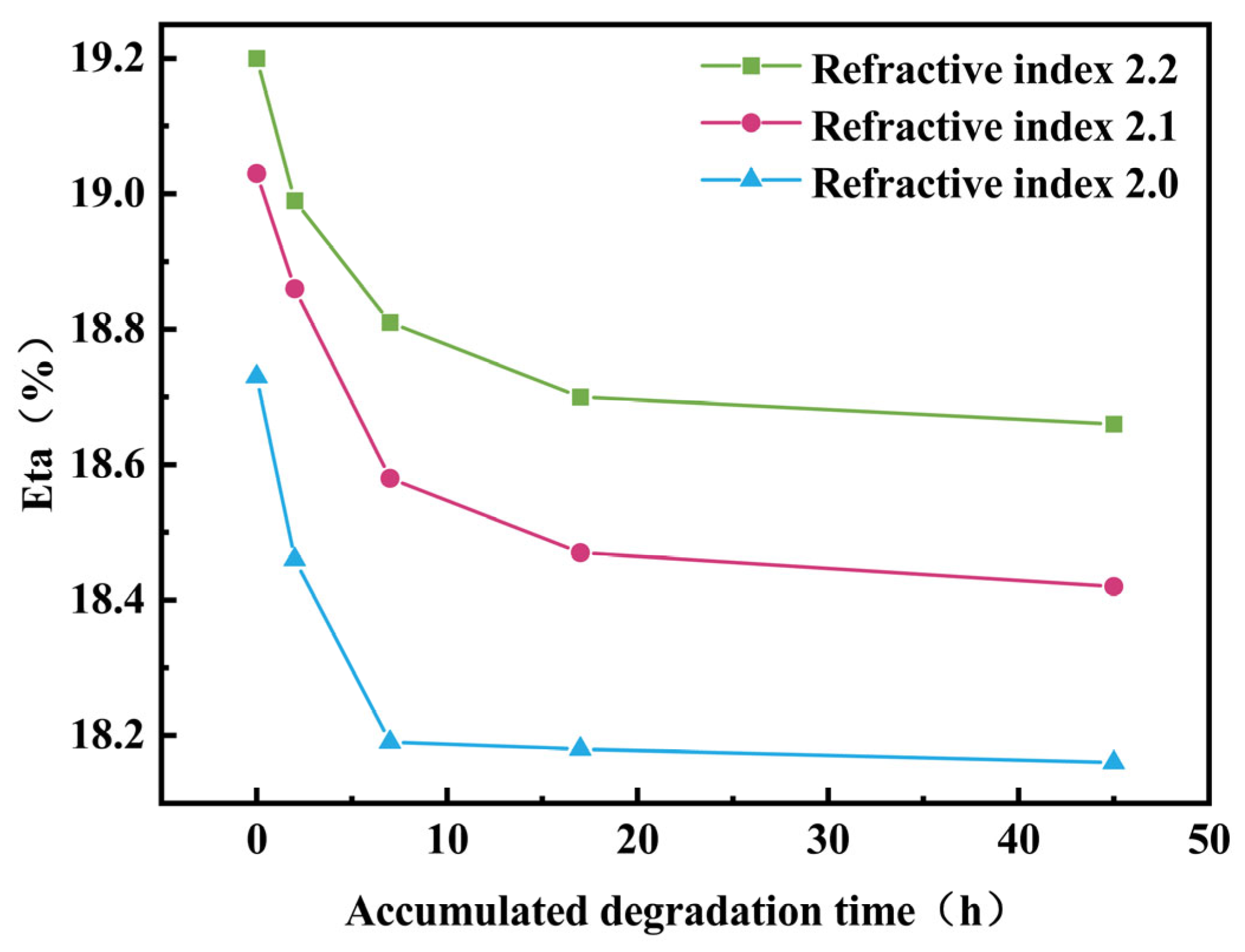
Figure 6 shows the trend of the conversion efficiency of polycrystalline PERC cells under 45 h LeTID with different SiN
x refractive indices. From the figure, we can see that conversion efficiency of cells with different refractive indices declined quickly within the first 10 h, then the degradation rate gradually slowed down and finally became stable. The conversion efficiency of cells with a refractive index of 2.2 decreased from 19.20% to 18.66% after 45 h degradation, with a decrease of 0.54%. Meanwhile, the conversion efficiency of cells with 2.0 and 2.1 refractive indices decreased by 0.57% and 0.61%, respectively. On the whole, the degradation pattern of solar cell samples with different refractive indices is consistent and the conversion efficiency was still the highest at 2.2 SiN
x refractive index after 45 h of degradation. The results showed that the different rear-side passivation conditions of SiN
x refractive index basically do not affect the photovoltaic degradation of the polycrystalline PERC cells. Under the different refraction indices, the decrease in conversion efficiency was around 0.55%.
Until now, we have optimized the relevant parameters for the Al
2O
3/SiN
x rear-side stacked passivation of PERC through the standard solar cell production line. To compare with other relevant research results, the optimal conversion efficiency of polycrystalline PERC batteries in other studies is shown in
Table 7. The optimal conversion efficiency in our research was 19.20%, which can be seen in
Table 6, under the optimized coating parameters of a 10.8 nm Al
2O
3 layer, 120 nm SiN
x layer and 2.2 SiN
x layer refractive index. Within the limited statistics, we can see that our polycrystalline PERC solar cell has certain advantages in conversion efficiency. In addition, due to our optimization about the parameters of Al
2O
3/SiN
x, the stacked passivation film on the rear side of the solar cell was completed on a standard solar cell production line, so the optimized parameters in our research can be directly applied to batch production.


