Abstract
Gasoline–air mixture explosions mostly occur in buried tank rooms, which are annular cylindrical confined spaces with circular arches. In this paper, explosion experiments at different gasoline–air mixture volume fractions are carried out in an annular cylindrical steel bench with a circular arch curvature radius of 900 mm and an annular half-perimeter to radial width ratio of 12π. The results show that the development process of explosion overpressure is clearly divided into four stages after first-order differentiation treatment. Compared with other types of confined spaces, 1.70% is still the most dangerous gasoline–air mixture volume fraction. However, this type of confined space has a larger inner surface area in the same volume condition, which will inevitably increase the heat absorption rate, reduce the chemical reaction rate, and slow down the flame propagation speed. Meanwhile, this spatial structure will inevitably make the explosion flames collide, which will promote positive feedback coupling between explosion flames and pressure waves, making the explosion more violent and dangerous. These results can provide theoretical and technical support for the explosion prevention design of buried tank rooms.
1. Introduction
Combustible gas explosion is always one of the most important research elements in the field of energy security. Combustible gas explosion accidents mostly occur in confined spaces (such as workshops and buried tank rooms) and are a great threat to industrial safety. The combustible gas explosion process always brings explosion flames and pressure waves. The flames and the pressure waves may constantly facilitate each other in the explosion development. Jiang and Li et al. called it the positive feedback coupling effect [1]. The coupling effect will encourage the explosion power to surge and lead to serious property loss and personal injury.
Combustible gas explosions are related to factors such as space type [2], combustible gas concentration [3], ambient pressure and temperature [4,5,6], ignition position and energy [7,8], branch structure, internal obstacle structure and vent mechanical strength [9,10,11]. The descriptions of combustible gas explosion mainly include explosion overpressure, limit, intensity and flow field development law, as well as the color, shape, speed and duration of explosion flames [12,13]. The initial gasoline quantity has a significant effect on the color and propagation characteristics of explosion flames in long and narrow confined spaces [14]. The concentration of OH radicals shows a law of first increasing and then decreasing in explosion processes [15], and explosion overpressure shows a sawtooth oscillation [16]. The explosion overpressure and pressurization speed also increase first and then decrease with the gasoline–air mixture concentration increasing [17] in volumetric confined spaces, and the overpressure peak increases with ignition energy increasing [18].
Gasoline is one of the most widely used petroleum products, and its leaking risk still exists in pipelines, workshops and buried tank rooms due to facility failure, error operation and accidents. Compared with other liquid fuels such as diesel and jet fuel, gasoline has a lower standard density, lower final boiling point, lower flash point and higher saturated vapor pressure, and is more easily spread to form a combustible gas in the same ambient conditions. Most of the previous studies focused on single component combustible gases such as hydrogen [19,20,21,22,23], methane [24,25,26], methanol [27], ethylene [28,29] and propane [30] in the field of gaseous explosions in confined spaces, and most of the explosion experiments were carried out in shock tubes (long, narrow confined spaces) [31] and pressure containers (volumetric confined spaces) [32]. However, the gasoline–air mixture is a kind of multi-component combustible gas, and its chemical reaction mechanism is more complex and its explosion characteristics are also different. Gasoline–air mixture explosions mostly occur in buried tank rooms. Buried tank rooms are annular cylindrical confined spaces with circular arches. This kind of confined space has an annular channel, the top of the channel is interconnected, and the channel width is usually narrow. In this paper, an experimental study of gasoline–air mixture explosion overpressure characteristics and flame propagation behavior has been investigated in an annular cylindrical confined space with circular arch, which is of practical significance for storage and transportation safety, and in particular theoretical and technical support is provided for the explosion prevention design of buried tank rooms.
2. Materials and Methods
Explosion experiments at different gasoline–air mixture volume fractions (δ) were conducted in the closed experimental bench of an annular cylindrical confined space with a circular arch.
2.1. Experimental System
The gasoline–air mixture explosion experimental system was composed of 5 modules, namely, bench, circulation, ignition, data detection and image acquisition, as shown in Figure 1. Although no research has shown that gasoline–air mixture explosion has a scaling effect on the spatial scale, in order to achieve better experimental results, the experimental bench was still built with the actual structure size of some buried tank rooms, as in the template. As shown in Figure 2a, the bench was composed of 3 parts: circular arch, outer wall and foundation with inner pot. The outer diameter (do) of the annular cylindrical space was 750 mm, while the inner diameter (di) was 690 mm, and the radial width was 30 mm. The inner cylinder height was 420 mm, while the outer cylinder height was 450 mm and the outer and inner surface curvature radius of the circular arch space was 900 mm. The surface area and volume of the confined space enclosed by the bench were 2.890 m2 and 0.047 m3, respectively, and the ratio of annular half-perimeter to radial width in this space (λ) was 12π, as defined in Equation (1). The circulation module was composed of the vacuum pump (ACO-328, Hailea Group Co., LTD, Chaozhou, China), pneumatic hose (TPU), jar (2500 mL, brown) and infrared analyzer (GXH-1050E, Jun Fang Physicochemical Science and Technology Institution, Beijing, China) to monitor and control δ. The ignition module, which was mainly composed of a high energy igniter (WGDH-5, Xi’an Ranxin Thermal engineering Technology Co., LTD, Xi’an, China) and ignition head, was used to ignite the premixed gasoline–air mixture. The data detection module was mainly composed of a computer, pressure sensor (ZXP610, 0–1 MPa, measurement accuracy: 0.25% FS, error: 0.1% FS, Baoji Zhixing sensor Co., LTD, Baoji, China), high performance dynamic signal test analyzer (DH8301, Donghua Testing Technology Co., LTD, Jingjiang, China) and supporting software to detect explosion overpressure inside the bench in real time. The image acquisition module, which was mainly composed of the observation window (Φ = 100 mm), high-speed camera (MEMRECAM HX-3e; nac Image Technology, Inc., Tokyo, Japan), lens (Nikon AF-S 24–85 mm ED; Nikon Corporation, Tokyo, Japan) and fill light (UCT-240-20, Wuhan Zhongchuang Lianda Technology Co., LTD, Wuhan, China), was used to acquire the local explosion flame propagation image in real time. The general arrangement of the pressure sensor, observation window and ignition head is shown in Figure 2b. Six observation windows were divided into three groups and evenly distributed on the outer wall of the bench, which was convenient for collecting the flame behaviors at different positions, as shown in Figure 2c. Take the vertical projection of the bench as the basic circle. When observation scheme A was used, the ignition head was distributed at a 150° angle from the camera; while observation scheme B was used, the angle became 180°.
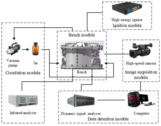
Figure 1.
Gasoline–air mixture explosion experimental system.

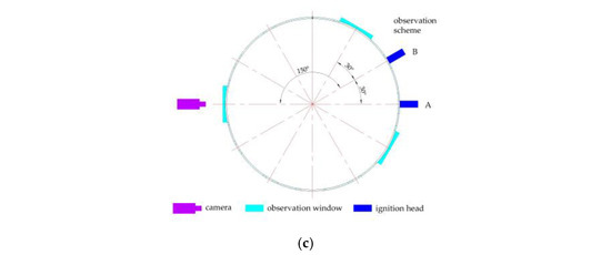
Figure 2.
Experimental bench of the annular cylindrical confined space with circular arch: (a) schematic diagram of the bench structure; (b) ignition head, pressure sensor and observation window; (c) observation scheme.
2.2. Experimental Scheme
The most dangerous δ values in various confined spaces were slightly different because of different experimental ambient conditions, but were all concentrated at about 1.70% [1,33,34]. In order to study gasoline–air mixture explosion overpressure characteristics and flame propagation behaviors more accurately, the experiments adjusted δ in the range of 1.40–2.00%, including from lean–burn conditions (δ = 1.40%, 1.50%) to suitable–burn conditions (δ = 1.60%, 1.70%, 1.80%) and then to rich–burn conditions (δ = 1.90%, 2.00%). The flow of the vacuum pump was about 82 L/min, the inner diameter of the intake hose was 12 mm, the length of exhaust hoses was 8 mm and the flow of the infrared analyzer was about 0.5 L/min. The ignition voltage was set at 1500 V ± 30 V, and ignition energy was set to 5 J. The igniter can generate a high voltage current in an instant, releasing energy to ignite the gasoline–air mixture. The data acquisition frequency of the pressure sensor was set to 10 k. A high-speed camera with the resolution of 72 ppi and the output image pixel size of 2560 × 1440 was used to shoot clear local flame images, and the frame rate was set at 1000 fps.
The experimental ambient temperature was maintained at 294.65 K ± 1.5 K, the atmospheric pressure was 99.2 kPa, and the air relative humidity was 72% RH. No. 92 gasoline for motor vehicles (national VI) was used to generate the gasoline–air mixture through the circulation module, adjusted δ to the target values, maintained gasoline–air mixture circulating in the bench for at least 3 min, and then stopped the circulation. After maintaining δ the target value for at least 1 min, all valves on the bench were closed to make the space of the bench into a sealed state, and then the premixed gasoline–air mixture was ignited, the explosion overpressure and flame images recorded, and the overpressure data and flame images processed. All valves were opened to exhaust the high pressure and high temperature fumes after explosion, and the bench was purged with a blower (2.3 m3/min) for at least 1 min. The bench was allowed to stand for at least 15 min to ensure that the experimental exhaust gas was discharged completely, and the bench was fully cooled to the ambient temperature and then the next group of experiments was conducted.
In gasoline–air mixture explosions in confined space, due to the influence of explosion flames, wall reflection and other factors, the measured explosion overpressure usually contains noise. In this paper, the sampling frequency of the pressure sensor was set to 10 k, and Origin 2021 software (version 9.8.0.200) was used to reduce the noise of explosion overpressure data using adjacent averaging and Savitzky–Golay methods. In this way, the authenticity of the data was restored as much as possible, and support was also provided for the in-depth analysis of the development and changing processes of explosion overpressure. In addition, the gasoline–air mixture explosion experiment in each condition was repeated at least 3 times to demonstrate the repeatability. On this basis, the statistical method was used to analyze the uncertainty of the measurement data, and the mean and standard deviation of the experimental data in the same condition were used to draw the error bar figures. It is important to note that large amounts of data or data not directly collected are not suitable for drawing error bar figures. Although these data have been analyzed for uncertainty, they are usually only presented directly in the form of scatter figures or dot figures.
3. Results and Discussion
3.1. Explosion Overpressure Development Process
Changes in the gasoline–air mixture explosion overpressure with time in the experimental bench of an annular cylindrical confined space with a circular arch at different δ are shown in Figure 3. The overpressure changing trend, which showed the development law of first increasing and then decreasing as time goes on, was basically the same in different conditions, and demonstrated one obvious overpressure peak (pmax). Li [1], Ghiasi [33] and Mitu et al. [34] found that the formation of pmax is related to the combustion reaction speed and explosion releasing speed in the gasoline–air mixture explosion process. pmax changed significantly at different δ. As shown in Figure 4a, pmax shows characteristics of first increasing and then decreasing with δ increasing. More specifically, pmax monotonically increased from 385.1 kPa to 443.0 kPa with δ in the range of 1.40–1.70%, but monotonically decreased to 394.4 kPa in the range of 1.70–2.00%, as listed in Table 1. Figure 4b illustrated the time taken to reach pmax (tmax) at different δ. With δ increasing in the range of 1.40–2.00%, tmax showed the characteristics of first decreasing and then increasing and reached minimum at δ = 1.70%, only 275.4 ms. Other researchers conducted similar studies with similar results. For instance, Cai Yunxiong et al. found that when δ = 1.70%, the pmax and tmax of the gasoline–air mixture explosion in a simulated vertical dome oil tank achieved the maximum value, 31.585 kPa, and the minimum value, 68 ms, respectively [35]. In addition, with δ increasing, the tmax decreasing speed was significantly greater than its increasing speed. More specifically, with δ increasing from 1.40% to 1.70%, tmax decreased by 81.6 ms, but from 1.70% to 2.00%, tmax only increased by 14.2 ms.
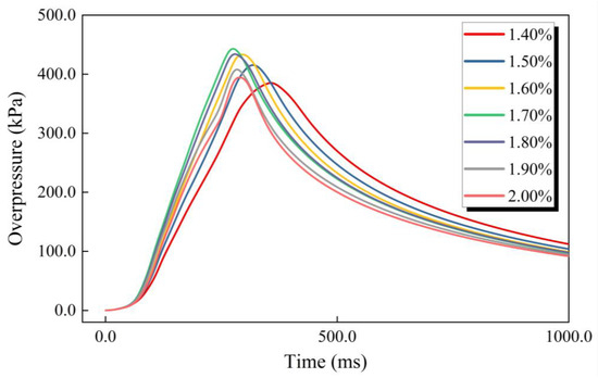
Figure 3.
The gasoline–air mixture explosion overpressure changing with time.
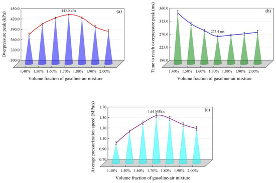
Figure 4.
Overpressure peak (pmax), time to reach overpressure peak (tmax) and average pressurization speed (uave) changing with the volume fraction of the gasoline–air mixture (δ): (a) pmax changing with δ; (b) tmax changing with δ; (c) uave changing with δ.

Table 1.
The overpressure peak (pmax), time to reach overpressure peak (tmax), average pressurization speed (uave) and explosion power index (EPI) at different volume fractions of gasoline–air mixture (δ).
In confined spaces, the damage degree of the gasoline–air mixture explosion is related to not only pmax but also tmax; that is, it is related to the average pressurization speed (uave). uave is defined in Equation (2). The changing of uave with δ is shown in Figure 4c and listed in Table 1. On the whole, uave showed the trend of first increasing and then decreasing with δ increasing and reached the maximum at δ = 1.70%. More specifically, uave increased from 1.08 MPa/s to 1.61 MPa/s with δ increasing from 1.40% to 1.70%; the increasing amplitude reached 49.1%, but from 1.70% to 2.00% uave decreased to 1.36 MPa/s and the decreasing amplitude was only 15.3%. Therefore, it can be seen that uave had a faster changing speed when δ < 1.70%; that is, δ had a more obvious effect on uave at this time. Generally, explosion power is represented by the deflagration index and explosion power index (EPI). According to the space characteristics of the experimental bench, EPI was selected to measure the gasoline–air mixture explosion damage degree, and the larger EPI was, the more serious the damage degree was. As defined in Equation (3), EPI is the product of pmax and uave. Figure 5 and Table 1 show EPI changing with δ. Obviously, with δ increasing in the range of 1.40–2.00%, EPI first increased and then decreased and reached maximum, 0.71 MPa2/s, at δ = 1.70%. The damage degree was the most serious in this condition.
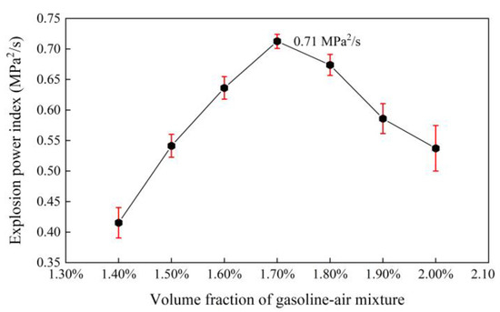
Figure 5.
Explosion power index (EPI) changing with the volume fraction of the gasoline–air mixture (δ).
The overpressure curve (Figure 3) roughly shows the development process of gasoline–air mixture explosion overpressure. Gasoline–air mixture explosions are a continuous process of chemical and physical change, and the explosion overpressure is a continuous function of time and can be derived in multiple orders. In order to explore the development process of explosion overpressure in more detail and more accurately, the instantaneous pressure changing speed (uins) was defined as the first derivative of overpressure at a certain time, as defined in Equation (4). Figure 6 shows uins changing with time at different δ. On the whole, the uins function had multiple extremums. The changing trends of uins at different δ were basically the same, first increasing, second oscillating, then decreasing, and finally increasing with time going on. More specifically, uins first monotonically increased with time going on, and second oscillated after attaining the first maximum of uins function (u1), and then monotonically decreased after attaining the last maximum (u2), and finally monotonically increased and tended to level after attaining the last minimum (u3). To some extent, these three extremums reflect the changing of the uins curve (Figure 6). The maximal value of function uins appeared at u1 when δ was in the range of 1.30–1.90%, but when δ attained 2.00% it appeared at u2, and the minimal value of function uins always appeared at u3 and did not change with δ changing, as shown in Figure 7.
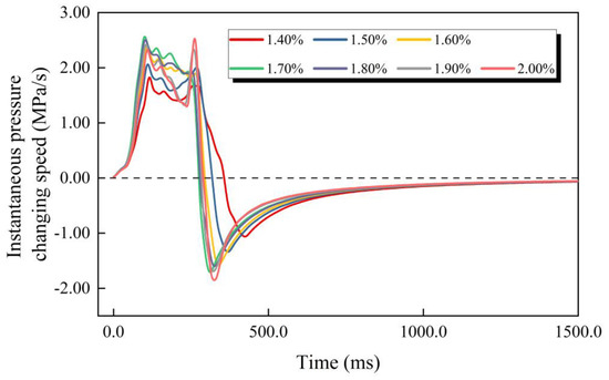
Figure 6.
The instantaneous pressure changing speed changing with time.
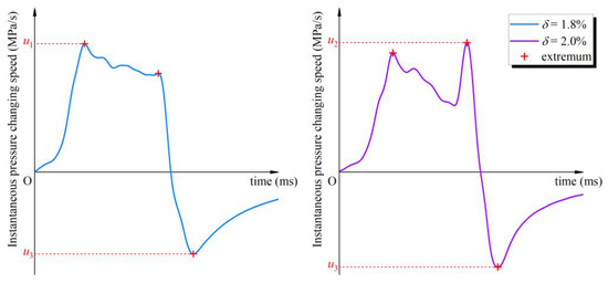
Figure 7.
The maximal and minimal instantaneous pressure changing speeds at different volume fractions of the gasoline–air mixture (δ).
U1 reflects the effect of δ on uins, as shown in Figure 8a. u1 showed a monotonic increasing trend when δ is in the range of 1.40–1.70%, while in the range of 1.70–2.00% u1 monotonically decreased. Obviously, u1 increased first, and then decreased with δ increasing, and attained the maximal value of 2.56 MPa/s at δ = 1.70%. However, as listed in Table 2, u2 and u3 did not show a similar trend. Figure 8b and Table 2 give the changing amplitudes of u2 compared with u1 (θ), as defined in Equation (5). On the whole, θ remained within 25.00%. θ exceeded 20.00% when δ was in the range of 1.60–1.80% and attained the maximal value at δ = 1.70%, exceeding 24.00%. However, θ only remained within 10.00% when δ was 1.40%, 1.50% or 1.90%, 2.00%. This shows that during the period from u1 to u2, although uins changing was tortuous, it was generally gentle.

Figure 8.
Relationship between u1 and u2: (a) the growth trend and comparison of a and b; (b) the changing amplitude of u2 compared with u1 (θ).

Table 2.
The first maximum (u1), last maximum (u2) and last minimum (u3) of instantaneous pressure changing speed functions, and the changing amplitude of u2 compared with u1 (θ) at different volume fractions of the gasoline–air mixture (δ).
3.2. Explosion Overpressure Variation Characteristics
Many scholars have divided the overpressure development process into stages in order to further explore the characteristics of explosion overpressure in confined spaces, but the bases for division have been different. As the first derivative of the explosion overpressure function, the positive and negative, large and small of uins can better describe the increasing and decreasing, fast and slow of the explosion overpressure. On this basis, define the instantaneous pressure changing acceleration (ains) as the second derivative of the explosion overpressure at a certain moment to judge the inflection point and the concavity and convexity of the overpressure curve, as defined in Equation (6). Referring to the changing trend of the uins curve, this paper divided the gasoline–air mixture explosion overpressure development process in annular cylindrical confined spaces with circular arches into four stages, accelerated pressurization, gradual pressurization, fast transition and gradual attenuation, and defined them as follows.
Taking the situation of δ = 1.70% as an example, as shown in Figure 9, define point α1 as the first trend demarcation point on the uins curve and let t1 be the first maximum point of the uins function; there is α1 (t1, u1). Similarly, point α2 and point α3 are defined as the second and third trend demarcation points, which are α2 (t2, u2) and α3 (t3, u3), respectively. t2 and t3 are, respectively, the last maximum point and the last minimum point of the function. The three trend demarcation points on the uins curve are distinguished from the different changing trends of uins function in each period. Back to the overpressure curve, define β0 as the origin of explosion time and overpressure; that is, β0 (0, 0). Corresponding to points α1, α2 and α3, define points β1, β2 and β3 as β1 (t1, p1), β2 (t2, p2) and β3 (t3, p3), respectively. Define βe as the end point of the explosion time and overpressure; that is, βe (te, pe). See Figure 10 for the corresponding relationship between the two kinds of demarcation points; the coordinates of each demarcation point at different δ are listed in Table 3.
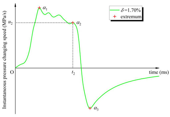
Figure 9.
Trend demarcation points on the instantaneous pressure changing speed curve.
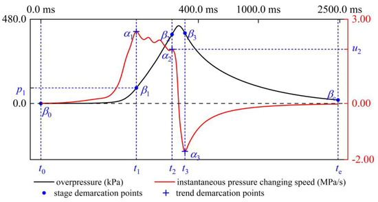
Figure 10.
Corresponding relationship between stage demarcation points and trend demarcation points, δ = 1.70%.

Table 3.
Coordinates of trend demarcation points and stage demarcation points at different volume fractions of the gasoline–air mixture (δ).
Still taking the situation of δ = 1.70% as an example, as shown in Figure 11, firstly define the period from the ignition time (t0) to t1 as the accelerated pressurization stage in the development process of explosion overpressure. Secondly, define the period from t1 to t2 as the gradual pressurization stage. Thirdly, define the period from t2 to t3 as the fast transition stage. Finally, define the period from t3 to the end of the explosion process (te) as the gradual attenuation stage. Figure 11 also shows the following characteristics of gasoline–air mixture explosion at various stages. In the accelerated pressurization stage, there are always ains > 0 and uins > 0, uins monotonously increases, then the explosion overpressure maintains a monotonous and accelerated increase, and the overpressure curve is concave. In the gradual pressurization stage, ains frequently changes sign and uins oscillates, but there is always uins > 0, so the explosion overpressure increases monotonously, but compared with the accelerated pressurization stage the overpressure growth speed tends to be steady and the concavity and convexity of overpressure curve changes alternately. In the fast transition stage, there is always ains < 0, uins monotonously decreases and changes from positive to negative, and then the explosion overpressure first increases and then decreases, and the overpressure curve is convex. It is worth mentioning that pmax appears at this stage. In the gradual attenuation stage, there are always ains > 0 and uins < 0, uins monotonously increases, then the explosion overpressure gradually attenuates and tends to be steady, and the overpressure curve is concave.
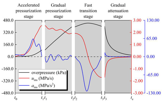
Figure 11.
The gasoline–air mixture explosion stages, δ = 1.70%.
The effect of δ on overpressure at the demarcation points of each stage is shown in Figure 12. Similar to the law of pmax, when δ is in the range of 1.40–2.00%, p1 first increases and then decreases with δ increasing, and at δ = 1.70% p1 exceeds 88.0 kPa, attaining the maximum. It is worth mentioning that the same trend also appears for p3. This may be due to the fact that after the overpressure curve passes through point β3 (t3, p3), the gasoline–air mixture explosion enters a gradually attenuated stage, the explosion overpressure decreases slowly, and the explosion process tends to be gentle and no longer violent, so point β3 (t3, p3) represents the severity of the explosion to some extent.
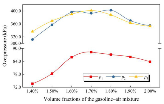
Figure 12.
p1, p2 and p3 changing with the volume fraction of the gasoline–air mixture (δ).
Figure 13 shows the situation of the explosion overpressure increment (Δp) of each stage. The pressurization proportion (η) is defined as the percentage of Δp to pmax at a certain stage in the process of explosion overpressure increasing. Figure 13a intuitively shows how much the Δp of each stage is, and Figure 13b shows the changing situation of η in each stage at different δ. Obviously, Δp in the gradual pressurization stage is the highest, exceeding 230.0 kPa, and at the same time η of this stage attains more than 60.00%. Δp in the accelerated pressurization stage is in the range of 70.0 kPa–90.0 kPa, and the η is maintained at about 20%, while Δp in the fast transition stage is the least, and the η is less than 20.00%. Figure 13a also shows the effect of δ on Δp in the process of pressurization. When δ is in the range of 1.60–1.80%, Δp in the gradual pressurization stage exceeds 300.0 kPa, which is obviously greater than Δp in the other δ. It is worth noting that, although the pmax produced by the explosion is the largest at δ = 1.70%, the Δp in the gradual pressurization stage is slightly smaller than that when the δ is 1.60% and 1.80%. Therefore, although the η in the gradual pressurization stage is larger at different δ, the Δp in this stage has no unique decisive effect on pmax, and the Δp in this stage cannot be used to characterize the severity of gasoline–air mixture explosions.

Figure 13.
Gasoline–air mixture explosion pressurization situations of each stage: (a) the effect of δ on Δp in the process of pressurization; (b) the changing situation of η in each stage at different δ.
3.3. Flame Propagation Behaviors
In experimental conditions, the shooting of explosion flames is inevitably disturbed by lens dispersion, background environment and other factors. The flame pictures before and after processing are shown in Figure 14. Figure 15 illustrates the effect of δ on the color of the explosion flame. On the whole, the colors of gasoline–air mixture explosion flames are mainly blue and yellow. When δ was in the range of 1.40–1.70%, the explosion flame only showed blue, while when δ increased to the range of 1.80–2.00%, the flame front showed blue and the flame behind the front showed yellow.

Figure 14.
Explosion flame picture processing.

Figure 15.
Flame color changing with volume fraction of the gasoline–air mixture (δ).
Figure 16a shows the cloudlike shape and linear shape of the explosion flames. Specifically, when δ was in the range of 1.40–1.70%, the explosion flame propagated to the unburned area with a cloudlike shape, while when δ increased to the range of 1.80–2.00%, it mainly took a linear shape. Obviously, these are the pictures of flame propagation taken under observation scheme A. The difference in flame propagation is due to the difference in combustion speed at different volume fractions of the gasoline–air mixture. Meanwhile, diffusional-thermal instability and hydrodynamic (Darrieus–Landau) instability also affect the flame dynamics. When δ was in the range of 1.40–1.70%, the unburned gas was continuously compressed with the flame propagation, resulting in a pressure gradient that forced the unburned gas into the combustion area, causing the flame to produce disturbance and present a cloudlike shape. When δ was in the range of 1.80–2.00%, the higher volume fraction reduced the influence of diffusional-thermal instability on the flame, and the tensile effect became the main factor affecting the flame shape. At this time, the flame propagation speed slowed down and the curvature of the flame front decreased, showing a linear shape. These flame propagation behaviors also prove the conclusion of Qi and Clanet et al. [36,37].

Figure 16.
Flame shapes: (a) flame propagation shapes; (b) flame shape during collision; (c) flame shape after collision.
There is bound to be a collision of gasoline–air mixture explosion flames in the annular cylindrical confined space with the circular arch because this type of confined space has an annular channel and the top of the channel is interconnected. Figure 16b shows the collision process of the explosion flame under observation scheme B. During the collision process, the flames in different directions approach each other quickly, which makes the combustion area present obvious disturbance. After collision, the combustion ends and the flame extinguishes quickly, as shown in Figure 16c. Although these are only local flame forms observed through the observation windows, they also reflect the propagation behaviors of gasoline–air mixture explosions in annular cylindrical confined spaces with circular arches.
The propagation process of local explosion flames on two–dimension planes (in the observation windows, Φ = 100 mm) is shown in Figure 17. The observation plane is a standard circle. Make chord A go through the two intersections between the flame front and the circle. With the explosion going on, the increasing direction of the perpendicular bisector of Chord A is the local flame propagation direction. It can be seen that the flame propagation direction of the gasoline–air mixture explosion is constantly changing. The local flame propagation speed (uf) can be calculated using Equation (7). Figure 18 illustrates the effect of δ on uf. When δ was in the range of 1.40–2.00%, uf first increased and then decreased with δ increasing and attained a maximal value of 3.45 m/s at δ = 1.70%. Other researchers have conducted similar studies with similar results. For instance, Li et al. found that when δ = 1.70%, the uf of gasoline–air mixture explosion in a confined circular pipe achieved the maximum value, almost 100 m/s [38]. On the whole, uf is very slow, and different in order of magnitude compared with the flame propagation speed of gasoline–air mixture explosion in long, narrow confined spaces and volumetric confined spaces [39,40]. Firstly, local flames observed in these experiments were all close to the collision area, which made the uf slow down. Secondly, the experimental bench had a narrow radial distance and a larger inner surface area in the same volume condition, which increased the explosion heat absorption speed, reduced the disturbance of unburned gasoline–air mixture and reduced the chemical reaction speed to make the uf slower.
where tf is the duration of the flame front from appearance to disappearance.

Figure 17.
Local flame propagation process.
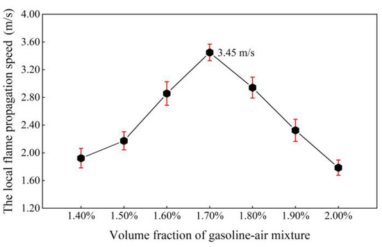
Figure 18.
The local flame propagation speed (uf) changing with the volume fraction of the gasoline–air mixture (δ).
4. Conclusions
Through the gasoline–air mixture explosion experiments and data processing and analysis, the conclusions are as follows:
- (1)
- The overpressure peak (pmax), average pressurization speed (uave), and explosion power index (EPI) first increased and then decreased as the gasoline–air mixture volume fraction (δ) increased during the explosion process in an annular cylindrical confined space with a circular arch, while the time to reach pmax (tmax) first decreased and then increased with δ increasing. The instantaneous pressure changing speed (uins) allowed the exploration of the development process of the explosion overpressure in more detail and more accurately, and showed the characteristics of first increasing, second oscillating, then decreasing, and finally increasing.
- (2)
- The explosion process was divided into four stages according to the characteristics he tuins curve: accelerate pressurization, gradual pressurization, fast transition and gradual attenuation stage. The explosion overpressure maintained an accelerated increase in the accelerated pressurization stage but a gradual increase in the next stage, and pmax always appeared in the fast transition stage.
- (3)
- The explosion flame mainly appeared in blue and yellow. The flame mainly appeared in a cloudlike shape and linear shape before the collision and only in a cloudlike shape during the collision, and extinguished quickly after collision. The local flame propagation speed (uf) first increased and then decreased with δ increasing, and attained the maximal value at δ = 1.70%.
- (4)
- The annular cylindrical confined space with a circular arch had a larger inner surface area in the same volume condition because the circumferential flame propagation distance was halved and the radial direction was narrow, which increased the explosion heat absorption speed, reduced the gasoline–air mixture chemical reaction speed and made the explosion flame propagate slowly. However, in this type of confined space, the structural characteristics of circumferential connection and top communication, which make the explosion flame collide inevitably, promoted positive feedback coupling between the flame and the pressure wave, making pmax and EPI larger and making the gasoline–air mixture explosion more violent and dangerous.
Author Contributions
Conceptualization, R.C., S.Z. and D.Z.; methodology, Y.C.; software, R.C. and D.H.; validation, D.Z.; formal analysis, P.Z.; investigation, D.H.; resources, X.Q.; data curation, P.Z. and X.Q.; writing—original draft preparation, R.C.; writing—review and editing, X.J.; visualization, Y.C.; supervision, X.J.; project administration, S.Z.; funding acquisition, X.J. All authors have read and agreed to the published version of the manuscript.
Funding
This research was funded by the Key Basic Research Program, grant number 2019-JCJQ-ZD-198-04, X.J.; the Postgraduate Funded Program, grant number JY2022C140, R.C.; the Postgraduate Research Innovation Program of Chongqing, grant number CYB22295, R.C., and CYS22756, X.Q.; the Youth Independent Innovation Science Foundation Program of ALA, grant number LQ-QN-202224, R.C., and LQ-QZ-202227, D.Z.; and the Science and Technology Research Program of Chongqing Municipal Education Commission, grant number KJZD-M202112901, P.Z.
Conflicts of Interest
The authors declare no conflict of interest.
Nomenclature
| δ | Volume fraction of gasoline–air mixture |
| do, di | External diameter, internal diameter of annular cylindrical space |
| λ | Ratio of annular half-perimeter to radial width in a space |
| Φ | Diameter of bench observation window |
| pmax | Overpressure peak |
| tmax | Time to reach pmax |
| uave | Average pressurization speed |
| EPI | Explosion power index |
| uins | Instantaneous pressure changing speed |
| α1, α2, α3 | Trend demarcation point |
| t1, t2, t3 | The first maximum point, the last maximum point, the last minimum point of uins function |
| u1, u2, u3 | The first maximum, the last maximum, the last minimum of uins function |
| θ | Changing amplitude of u2 compared with u1 |
| ains | Instantaneous pressure changing acceleration |
| β0, β1, β2, β3, βe | Stage demarcation point |
| t0, te | Ignition time, explosion end time |
| p0, p1, p2, p3, pe | Overpressure of each stage demarcation points |
| Δp | Overpressure increment |
| η | Pressurization proportion |
| uf | Local flame propagation speed |
| tf | Duration of flame front from appearance to disappearance |
References
- Li, G.; Zheng, K.; Wang, S.; Chen, W. Comparative study on explosion characteristics of hydrogen and gasoline vapor in a semi-confined pipe based on Large Eddy Simulation. Fuel 2022, 328, 125334. [Google Scholar] [CrossRef]
- Movileanu, C.; Gosa, V.; Razus, D. Explosion of gaseous ethylene-air mixtures in closed cylindrical vessels with central ignition. J. Hazard. Mater. 2012, 235, 108–115. [Google Scholar] [CrossRef]
- Yao, Z.; Deng, H.; Dong, J.; Wen, X.; Zhang, X.; Wang, F.; Chen, G. On explosion characteristics of premixed syngas/air mixtures with different hydrogen volume fractions and ignition positions. Fuel 2020, 288, 119619. [Google Scholar] [CrossRef]
- Askari, O.; Moghaddas, A.; Alholm, A.; Vien, K.; Alhazmi, B.; Metghalchi, H. Laminar burning speed measurement and flame instability study of H2/CO/air mixtures at high temperatures and pressures using a novel multi-shell model. Combust. Flame 2016, 168, 20–31. [Google Scholar] [CrossRef]
- Leo, Y.; Zhang, B. Explosion behavior of methane-air mixtures and Rayleigh-Taylor instability in the explosion process near the flammability limits. Fuel 2022, 324, 124730. [Google Scholar] [CrossRef]
- Liang, W.; Mével, R.; Law, C.K. Role of low-temperature chemistry in detonation of n -heptane/oxygen/diluent mixtures. Combust. Flame 2018, 193, 463–470. [Google Scholar] [CrossRef]
- Jin, K.; Wang, Q.; Duan, Q.; Chen, J.; Sun, J. Effect of ignition position on premixed hydrogen-air flame quenching behaviors under action of metal wire mesh. Fuel 2020, 289, 119750. [Google Scholar] [CrossRef]
- Wang, C.; Guo, J.; Yang, F.; Zhang, G. Effects of ignition position on the ignitability and flame behavior of stratified gasoline vapor. Fuel 2021, 304, 121361. [Google Scholar] [CrossRef]
- Li, G.; Wang, X.; Zhao, X. Experimental study on explosion characteristics of ethanol-gasoline blended fuels. J. Loss. Prevent. Proc. 2020, 64, 104083. [Google Scholar] [CrossRef]
- Peng, H.; Huang, Y.; Deiterding, R.; Luan, Z.; Xing, F.; You, Y. Effects of jet in crossflow on flame acceleration and deflagration to detonation transition in methane–oxygen mixture. Combust. Flame 2018, 198, 69–80. [Google Scholar] [CrossRef]
- Wang, Q.; Jin, S.; Luo, Z.; Dai, A.; Wang, Q.; Li, Z. Flame propagation characteristics of methane explosion under different venting conditions. Fuel 2023, 334, P1. [Google Scholar] [CrossRef]
- Guo, J.; Liu, X.; Wang, C. Experiments on vented hydrogen-air deflagrations: The influence of hydrogen concentration. J. Loss. Prevent. Proc. 2017, 48, 254–259. [Google Scholar] [CrossRef]
- Li, G.; Wang, X.; Xu, H.; Liu, Y.; Zhang, H. Experimental study on explosion characteristics of ethanol gasoline-air mixture and its mitigation using heptafluoropropane. J. Hazard. Mater. 2019, 378, 120711. [Google Scholar] [CrossRef]
- Pan, C.; Li, G.; Wang, X. Effects of top vent locations and gasoline volumes on vented gasoline vapor explosion in closed small-scale vessel. Fuel 2020, 277, 118226. [Google Scholar] [CrossRef]
- Jiang, X.; Yu, B.; Xu, J.; Wang, W.; Jiang, J.; Zhao, Y. Study on concentration distribution of radical groups of gasoline-air explosion in long-narrow confined space based on OH-PLIF. CIESC J. 2020, 71, 5352–5360. [Google Scholar]
- Wang, B.; Du, Y.; Qi, S.; Yuan, G.; Wang, S. Oscillation propagation characteristics of gasoline-air mixture explosion in elongated closed tubes. J. Vib. Shock. 2017, 36, 97–103. [Google Scholar]
- Wei, S.; Du, Y.; Wang, S.; Li, M. Experimental study on deflagration characteristics of gasoline-air mixture in confined space with different shapes. J. Saf. Sci. Technol. 2017, 13, 41–47. [Google Scholar]
- Wang, S.; Du, Y.; Gao, J.; Liang, J.; Zhang, P.; Li, G. An experimental study of internal gasoline-air mixture explosion loading in a semi-underground vault tank. J. Vib. Shock. 2017, 36, 239–244. [Google Scholar]
- Chang, X.; Bai, C.; Zhang, B. The effect of gas jets on the explosion dynamics of hydrogen-air mixtures. Process. Saf. Env. 2022, 162, 384–394. [Google Scholar] [CrossRef]
- Rui, S.; Wang, C.; Guo, S.; Jing, R.; Li, Q. Hydrogen-air explosion with concentration gradients in a cubic enclosure. Process. Saf. Environ. 2021, 151, 141–150. [Google Scholar] [CrossRef]
- Rui, S.; Wang, C.; Luo, X.; Li, Q.; Zhang, H. Experimental study on the effects of ignition location and vent burst pressure on vented hydrogen-air deflagrations in a cubic vessel. Fuel 2020, 278, 118342. [Google Scholar] [CrossRef]
- Shen, X.; He, X.; Sun, J. A comparative study on premixed hydrogen—air and propane—air flame propagations with tulip distortion in a closed duct. Fuel 2015, 161, 248–253. [Google Scholar] [CrossRef]
- Wang, Q.; Luo, X.; Wang, C.; Liu, Y.; Zhou, P.; Li, B. Experimental study on external explosion for vented hydrogen deflagration in a rectangular tube with different vent coefficients. Process. Saf. Environ. 2022, 158, 331–339. [Google Scholar] [CrossRef]
- Sun, S.; Qiu, Y.; Xing, H.; Wang, M. Effects of concentration and initial turbulence on the vented explosion characteristics of methane-air mixtures. Fuel 2020, 267, 117103. [Google Scholar] [CrossRef]
- Ji, H.; Lu, R.; Yang, K.; Jiang, J.; Xing, Z.; Guo, J. Experimental study on methane explosion suppression by heptafluoropropane drived modified ABC powder. Process. Saf. Environ. 2023, 170, 623–635. [Google Scholar] [CrossRef]
- Na Inna, A.M.; Phylaktou, H.N.; Andrews, G.E. Explosion flame acceleration over obstacles: Effects of separation distance for a range of scales. Process. Saf. Environ. 2017, 107, 309–316. [Google Scholar] [CrossRef]
- Saeed, K. Determination of the explosion characteristics of methanol—Air mixture in a constant volume vessel. Fuel 2017, 210, 729–737. [Google Scholar] [CrossRef]
- Wang, K.; Su, M.; Wei, L.; Chen, S.; Kong, X.; Fang, Y. Effect of initial turbulence on explosion behavior of stoichiometric methane-ethylene-air mixtures in confined space. Process. Saf. Environ. 2022, 161, 583–593. [Google Scholar] [CrossRef]
- Cao, Y.; Gao, K.; Li, B.; Xie, L.; Pan, X. Influence of vent size and vent burst pressure on vented ethylene-air explosion: Experimental and numerical study. Process. Saf. Environ. 2023, 170, 297–309. [Google Scholar] [CrossRef]
- Keisuke, N.; Akira, Y.; Makihito, N. Experiments and numerical simulation on the suppression of explosion of propane/air mixture by water mist. Combust. Flame 2021, 223, 192–201. [Google Scholar]
- Yu, M.; Wan, S.; Zheng, K.; Guo, P.; Chu, T.; Yuan, Z. Influence on the methane/air explosion characteristics of the side venting position in a pipeline. Process. Saf. Environ. 2017, 111, 292–299. [Google Scholar] [CrossRef]
- Giurcan, V.; Mitu, M.; Razus, D.; Oancea, D. Pressure and temperature influence on propagation indices of n-butane—Air gaseous mixtures. Process. Saf. Environ. 2017, 111, 94–101. [Google Scholar] [CrossRef]
- Ghiasi, G.; Ahmed, I.; Swaminathan, N. Gasoline flame behavior at elevated temperature and pressure. Fuel 2019, 238, 248–256. [Google Scholar] [CrossRef]
- Mitu, M.; Razus, D.; Giurcan, V.; Oancea, D. Normal burning velocity and propagation speed of ethane-air: Pressure and temperature dependence. Fuel 2015, 147, 27–34. [Google Scholar] [CrossRef]
- Cai, Y.; Jiang, X.; Wang, S.; Liang, J.; Zhang, P. Experimental study on explosion overpressure and flame propagation characteristics of simulated vertical dome oil tank. J. Loss. Prevent. Proc. 2022, 76, 104752. [Google Scholar] [CrossRef]
- Clanet, C.; Searby, G. On the “tulip flame” phenomenon. Combust. Flame 1996, 105, 1. [Google Scholar] [CrossRef]
- Qi, S.; Du, Y.; Zhang, P.; Li, G.; Wang, S.; Li, Y.; Dong, T. Experimental study of gasoline vapor deflagration in a duct with an open end. Combust. Flame 2018, 193, 16–24. [Google Scholar] [CrossRef]
- Li, J.; Jiang, X.; Li, J.; Yu, B.; Zhang, L.; Zhao, Y. Study on influence of length-diameter ratio on explosion characteristics and flame propagation laws of gasoline-air mixture in pipeline. J. Saf. Sci. Technol. 2020, 16, 88–94. [Google Scholar]
- Guo, J.; Li, J.; Tang, Z.; Wang, X.; Zhuang, Y.; Zhang, S.; Duan, Z.; Li, C. Flame propagation in gasoline vapor-air mixtures with concentration gradient in a closed duct. Fuel 2020, 270, 117508. [Google Scholar] [CrossRef]
- Wang, S.; Yan, Z.; Li, X.; Li, G.; Guo, H.; Wu, D. The venting explosion process of premixed fuel vapour and air in a half-open vessel: An analysis of the overpressure dynamic process and flame evolution behaviour. Fuel 2020, 268, 117385. [Google Scholar] [CrossRef]
Disclaimer/Publisher’s Note: The statements, opinions and data contained in all publications are solely those of the individual author(s) and contributor(s) and not of MDPI and/or the editor(s). MDPI and/or the editor(s) disclaim responsibility for any injury to people or property resulting from any ideas, methods, instructions or products referred to in the content. |
© 2023 by the authors. Licensee MDPI, Basel, Switzerland. This article is an open access article distributed under the terms and conditions of the Creative Commons Attribution (CC BY) license (https://creativecommons.org/licenses/by/4.0/).