Article

The Method of the Secondary Arc Suppression in Cycle Single-Phase Auto Reclose with High-Level Penetration Renewable Energy Sources

by
Milan Belik
1,2,*,
Vladyslav Kuchanskyy
3 and
Olena Rubanenko
4,5,6
1
Department of Electrical Power Engineering, Faculty of Electrical Engineering, University of West Bohemia, 30614 Pilsen, Czech Republic
2
Department of Simulation RES, Czech Photovoltaic Association, z.s., Teslova 1202/3, 30100 Pilsen, Czech Republic
3
Institute of Electrodynamics of NAS of Ukraine, Str. Peremohy, 56, 03057 Kiev, Ukraine
4
Research and Innovation Center for Electrical Engineering (RICE), Faculty of Electrical Engineering, University of West Bohemia, 30614 Pilsen, Czech Republic
5
Department of Power Plants and System, Vinnitsya National Technical University, 21000 Vinnitsya, Ukraine
6
Department of Wind Power, Institute of Renewable Energy, 02094 Kiev, Ukraine
*
Author to whom correspondence should be addressed.
Energies 2023, 16(19), 6880; https://doi.org/10.3390/en16196880
Submission received: 28 June 2023 / Revised: 10 September 2023 / Accepted: 21 September 2023 / Published: 29 September 2023
(This article belongs to the Section A: Sustainable Energy)

Abstract

:
Renewable energy sources have a multifaceted impact on power grids, ranging from the reliability and quality of electricity to the selective impact on equipment. While renewables used to be distributed in distribution networks, now their capacity is commensurate with thermal power plants and their impact on the grid should not be underestimated. According to the statistics on the interruption of the bulk electric networks, one of the main reasons for emergency shutdowns of extra high-voltage power lines are single-phase short circuits. The problem of mathematical modeling of the limit modes in terms of static stability is very relevant to the design and operation of electric power systems (EPS). Calculations of limit modes have both an independent value and a component of other electrical engineering tasks related to ensuring the required level of reliability and cost-effectiveness of the operation of the united PS. Despite the great degree of development of issues of planning and control of electric modes, system accidents associated with unacceptable loads of network elements occur in the Ukrainian energy industry. Non-phase modes regularly occur in electric power systems, which can lead to an unacceptable load of intersystem network elements, which imposes significant restrictions on their throughput. Single-phase short circuits are more than 95% of other damage that occurs in the line. The use of single-phase auto reclose on the transmission lines allows disconnecting only the damaged phase for a short period of time and not the entire transmission line. This action preserves the transit of electricity along the line and prevents the violation of the stability of parallel operation. To achieve this, the current-free pause of the single-phase auto reclose should last as short as possible. On the other hand, an important task to be solved when using single-phase auto reclose is to choose the minimum duration of the current-free pause necessary for its success. The problem studied in this paper deals with the safety and correct operation of transmission lines (TS) of the Ukrainian bulk power system in special conditions (not predictable, changing due to frequent attacks). For a quickly changing configuration, the power grid uses switches, and in the case of ultra-high voltage, the TS needs to solve the problem of secondary arc currents and recovering stresses in the place of arc burning after its extinction. One of the methods of reducing secondary arc currents and recovering stresses in the place of arc burning after its extinction is the implementation of single-phase automatic reclosing (SPAR). The main theoretical result of the paper is a proposed mathematical model of a compensated power transmission line based on the use of matrix n-poles, which makes it possible to model in detail stationary power transmission modes, including the SPAR mode. The proposed mathematical model of three-phase power transmission has been created using phase coordinates and can be used for the analysis of complex asymmetric modes. The main practical result of the paper is physically interpreted simplified models of three-phase TS, which can be used for the study of resonant overvoltages and currents of the feeding arc in non-full-phase circuit SPAR. The conclusion that can be drawn from the obtained results points out which line lengths must take into account the influence of longitudinal asymmetry when choosing the inductive resistance, i.e., take into account the dependence of the mode parameters on the location of the damaged phase. The observed results show that the largest values of the multiplicity of overvoltages will take place in phase B. The novelty of the work is the developed technique that makes it possible to determine in advance, depending on the disconnected phase of the line, the values of the primary conductivities of the STC (static thyristor compensators) and the corresponding angles of control of the thyristor switches, which satisfy almost complete compensation of the secondary arc at any point of the line in the specific condition (hard) of the bulk power system operation.

1. Introduction

Despite the large amount of deep and extensive work, the use of a single-phase automatic reclosing (SPAR) is one of the main ways to increase the operational reliability of extended extra-high-voltage (EHV) transmission lines. Successful implementation of the SPAR with unstable single-phase short circuits requires the adoption of special measures to reduce the secondary arc to values allowing the self-extinction of the arc. This will be sufficiently reliable for an acceptable period of time from the point of view of ensuring dynamic stability of the no-current pause of the SPAR [1,2,3,4].
Authors of [5] declared that the reclosing relay based on some methods was sophisticated and complicated, and they developed the concept of the decomposition quality factor proposed to determine the mode number and hence the fault type (but this approach must be adapted to the Ukrainian conditions).
The authors of the manuscript [6] proposed an innovative method for an adaptive single-phase auto reclosing based on the moving average filter-quadrature signal generator that was developed to determine secondary arc extinction time for high-voltage transmission lines with shunt reactors and high-level penetration RES—but it must be adapted to the Ukrainian conditions of operation.
The paper proposes a multichannel convolutional neural network for detecting the extinction of secondary arcs in compensated transmission lines; however, it must take into account expert information and be adapted to real conditions of operation [7].
Traditionally, the reduction of the secondary arc is achieved by connecting shunt reactors (SHR) and special compensation reactors installed on overhead lines (OHL) in neutral [8,9,10,11,12]. The efficiency of this measure increases when the reactivity of the compensation reactors changes depending on the phase of the line to be switched off and on to the direction of power transmission. It is clear that EHV transmission lines with a single cycle of wire transposition have significant phase-by-phase asymmetry, which increases with lengthening the transposition step and when performing lines with close phases. Full compensation of phase-wise unbalanced partial line capacitances and, hence, the arc feeding currents cannot be carried out using four-beam reactors with phase-symmetric parameters [13,14,15,16,17].
Calculations have shown that it is impossible to compensate the arc feeding currents to acceptable values even with the commutation of compensation reactors in the neutrals of the SR in a number of EHV power transmissions. Significant opportunities for compensation of the secondary arc have emerged due to static thyristor compensators (STC) with phase-independent control. It is possible to select the equivalent parameters of the STC in such a way as to completely compensate for the corresponding system of partial line capacitances and thereby reduce the secondary arc currents to almost zero using automatic changes of the control angles of the thermistor switches [14,15,16,17,18,19,20]. In this case, the control angles of the thermistor switches of the STC will depend only on the disconnected phase of the line. They will not depend on the magnitude and direction of the power transmitted in the pause of the SPAR along the non-disconnected phases of the line, as well as on the location of the short circuit. For a specific line, the steering angles can be predefined.
Successful elimination of arc short circuits in the SPAR cycle is, on the one hand, determined by the characteristic of the recharge arc arising in long air gaps. On the other hand, the effectiveness of methods used for reducing secondary arc currents and recovering depends on the location of the arc and its extinction. Implementation of the SPAR in AC power transmission is hampered by the presence of a place recharge short circuit on the side of non-disconnected phases [19,20,21,22,23,24]. Mode parameters determining the conditions for extinguishing the secondary arc are as follows: secondary current of the arc flowing in the arc before it is extinguished, Id; recovery stress in the place of short circuit after the extinction of the secondary arc current.

2. Parameters of the Extra-High-Voltage Transmission Line

Successful mitigation of the supply arc in the extra-high-voltage power lines, 750 kV, requires the suppression of two components: electromagnetic and electrostatic. The electrostatic component of the secondary arc can be potentially decreased by a compensation reactor, which compensates for the electrostatic connection between the disconnected phase and the phases that remain in operation. The use of a compensating reactor is a traditional measure to suppress the secondary arc that requires calculations and selection of resistance values for a specific EHV transmission line.
An increase in the reliability of the transmission of electrical energy through extra-high-voltage overhead lines (EHV OL) is closely related to the effectiveness of eliminating single-phase unstable short circuits (SC). SC are the reason for the most frequent disruption of the normal operation of electrical systems. The restoration of the normal power transmission mode after the occurrence of a single-phase short circuit is accompanied by the stages of short-circuit tripping by linear switches on the side of the systems, extinguishing the recharge arc, followed by restoring a certain voltage in the phase and re-enabling the disconnected phase. The total time of absence of transmission of electrical energy in one phase is characterized by a no-current pause of the SPAR [22,23,24,25,26].
Decreasing the pause reduces the duration of power transmission in the open phase mode, increases the dynamic stability of power systems that are electrically connected by a power line, helps reduce mechanical moments on the generator shafts, and reduces the flow of emergency control actions for them. The duration of the burning of the secondary arc in the disconnected phase is determined by the mode parameters of the pause of the SPAR—the secondary arc current, which heats the arc channel and prevents the arc from self-extinguishing, and the voltage recovering at the point of the short circuit after the arc is extinguished.
The restoration of the full three-phase model of operation of the power transmission line ends with the reclosure of the disconnected phase, which is accompanied by overvoltage. The surge arrester installed at the end of the OL, opposite to the turn-on side, limits the overvoltage to a permissible level; however, in the middle part of the OL, overvoltages can significantly exceed the specified value. Incomplete deionization of the arc channel leads to the weakening of the dielectric strength of the insulating gap and can cause a repeated breakdown of the insulation, i.e., a short circuit (especially in the case of small no-current pauses) [23,24,25,26,27,28,29,30].
Due to the noted circumstances, as well as the increase in the reliability of the electrical equipment in the substation operation, with a decrease in the flow and amplitude of overvoltages, the latter should be minimized. In accordance with the above, this section sets the goal of analyzing all stages of the SPAR mode in OL of various designs, including the consideration of both stationary and transient modes of the current-free pause of the SPAR. The process of restoring the normal operating mode, i.e., re-enabling the phase in the SPAR cycle, as well as developing a set of technical measures, ensures the normal course of these modes.
When the compensation conditions are met, the arc secondary current short circuit at the beginning and end of the transmission line are identical and equal to zero (if it is assumed that the active resistances of the transmission elements are equal to zero).
Physically, this means that the parameters of the STC are selected in such a way as to fully compensate for the partial capacitance of the emergency phase to ground and the partial capacitances between the emergency and undamaged phases. In this case, the values of the equivalent reactances of the secondary arc at the ends of the line increase to infinity. This means that the secondary arc currents vanish regardless of the operating parameters of the non-disconnected phases, i.e., regardless of the course of electromechanical transients caused by the occurrence of a short circuit and the disconnection of the line phase.
Let us consider the use of the STC in the pause modes of the SPAR in the example of a power transmission that includes an EHV line. Both ends have the STC installed (Figure 1). Currents and voltages from Equation (1) are shown in Figure 1.
The equations of stationary modes of power transmission containing a line with a single cycle of wire transposition with STC installed at its ends can be written in phase coordinates in the following form:
{ I B = I a r c b + ( Y L b + Y S T C b ) U b Y L b . e . U e I E = I a r c e + Y L e . b . U e ( Y L e + Y S T C e ) U e
where I B , I E are matrix columns of the beginning (index b) and end (index e) power transmission currents; I a r c b , I a r c e are matrices of short-circuit currents (when the line phase is off, there are secondary arcs at the beginning and end of the line); U B , U E are phase voltage matrices at the beginning and end of the line; Y L b , Y L e , Y L b . e . , Y L e . b . are matrices of line conductivities (own and mutual), taking into account the execution of lines with a given geometry of the suspension of wires and cables, the method of grounding the cables, and the length of individual non-transposed sections of the line. Y S T C b , Y S T C e are the conductivity matrices of the STC, established at the beginning and end of the line.
The general algorithm for obtaining the matrix of line conductivities Y L b , Y L e , Y L b . e . , Y L e . b . is described in [3,4,5,6,7,8,9,10]. The values of the elements of the conductivity matrices of the line are considered below and are determined by this algorithm.
The article examines an EHV line with a length of 320 km and with the lengths of the non-transposed sections of 106, 100, and 114 km. The considered line structures of the conductivity matrix, determined in accordance with [3], have the following meanings:
Y L b . e . = [ 9.5289 2.5796 2.5515 2.5726 9.5389 2.5616 2.5406 2.5562 9.5056 ] 10 4 + j [ 10.168 2.0004 2.0452 1.9981 10.159 2.0353 2.028 2.0328 10.185 ] 10 3 S ; Y L e . b . = [ 9.5289 2.5726 2.5406 2.5796 9.5389 2.5562 2.5516 2.5616 9.5056 ] 10 4 + j [ 10.168 1.9981 2.0428 2.004 10.159 2.0328 2.0452 2.0353 10.185 ] 10 3 S ; Y L e . = [ 9.5809 2.5880 2.5519 2.5880 9.6023 2.5574 2.5519 2.5674 9.582 ] 10 4 + j [ 9.5127 1.9981 2.0428 1.9766 9.4971 1.9419 1.9837 1.8419 9.515 ] 10 3 S .
At the ends of the line, STC of the same power are installed. With this b n o m ~ = Q n o m / U max 2 = 7.6389 10 4 S ; x t = 132.25   Ω . The value of the nominal primary conductivity of STC b n o m = 8.4973 10 4 S .
Neglecting the active resistances of wires, cables, and ground, these matrices could have this form:
{ Y L b = j [ b L 11 b b L 12 b b L 13 b b L 12 b b L 22 b b L 23 b b L 13 b b L 23 b b L 33 b ] Y L e = j [ b L 11 e b L 12 e b L 13 e b L 12 e b L 22 e b L 23 e b L 13 e b L 23 e b L 33 e ] Y L b . e . = j [ b L 11 b L 12 b L 13 b L 12 b L 22 b L 23 b L 13 b L 23 b L 33 ] Y L e . b . = j [ b L 11 b L 12 b L 13 b L 12 b L 22 b L 23 b L 13 b L 23 b L 33 ]
The conductivity matrices of the STC, connecting the first harmonic phase currents with the voltages at the input of the STC, under the assumption of the sinusoidal shape of the input voltages and without taking into account the active parameters of the STC elements, can be written as follows:
Y STC b = j [ b 11 b b 12 b b 13 b b 12 b b 22 b b 23 b b 13 b b 23 b b 33 b ] Y STC e = j [ b 11 e b 12 e b 13 e b 12 e b 22 e b 23 e b 13 e b 23 e b 33 e ]
b i i b , b i i e , b i j b , b i j e are equivalent conductivity STC, depending on the connection diagram of the transformer windings; the values of the primary controlled conductivities b a b , b b c , b c a and the conductivity of the reactor b N are included in the neutral of the primary winding of the STC transformer (Figure 1).
The conditions for compensating the secondary arc at different phases of the overhead line can be obtained from Equation (1), taking into account (2) and (3). These conditions of compensation, which connect the equivalent conductivity of the STC with the parameters of the line, are presented in Table 1, where h 11 e , h 22 e , h 33 e are arbitrary parameters characterizing the degree of compensation of the phase capacitance of the line at the receiving end of the overhead line.

3. Technical Restrictions Procedures for the Choice of Values of Parameters of the STC

Though it is essential to fulfill the conditions for compensation of the secondary arc at the ends of the line, it does not provide full compensation at a short circuit at any intermediate point. In addition, the terms of compensation were obtained without taking into account active resistances of line wires, cables, and earth. Calculations of the arc currents depend on the location of the short circuit when taking into account the active resistances of the power transmission elements. It was shown that their rim values both at intermediate points of the line and at its ends do not exceed 3 A. Consequently, the control of the STC based on the conditions for compensating the secondary arc currents at the ends of the line ensures reliable extinction of the secondary arc at a short circuit at any intermediate point on the line.
The steady-state values of currents and voltages on the disconnected phase of the line are considered. Experimental data show that, in addition to the fundamental harmonic, the composition of the arc feeding current includes the aperiodic component and higher harmonics, the presence of which worsens the conditions for extinguishing the feeding arc. The indicated components of the arc feeding current are reduced to negligible values in 0.1–0.3 s, which, provided that the fundamental harmonic is compensated, will ensure reliable extinguishing of the feeding arc during the free-current pause of the SPAR.
The equivalent conductivities b i i and b i j of the STC, which correspond to the obtained compensation conditions, depend on the primary parameters of the STC. The type of dependencies is determined by the connection diagram of the STC transformer windings. Below is the considered STC circuit, the single-phase two-winding transformers of which are connected in a group according to the “star with grounded neutral–delta” scheme (Figure 1). The elements of reactive power consumption STC include 16 thermistor–reactor groups (TRG). Current regulation is carried out by stepwise switching on of 14 sections of the TRG and smooth regulation of the angles of ignition of the thermistors in two sections of the TRG. In this case, the level of higher harmonics generated by the STC with phase asymmetric control of its reactances will be insignificant and will not cause a noticeable increase in the arc feed current in the pause mode of the SPAR.
The connection of the secondary windings of the transformer in a triangle is equivalent to the inclusion of significant capacitive conductivities between the phases of the power transmission, along which the arc is fed during the pause of the SPAR. For the STC to compensate for the phase-to-phase capacitive conductance of the line, its zero-sequence reactance must be greater than its positive-sequence resistance. For this, it is necessary to include compensation reactors with high reactance in the neutral of the STC transformers [4,5,6,7,8,9,10,11,12,13,14,15]. In this case, the voltage in the neutral of the transformers will be 0.3–0.4 of the nominal phase voltage of the power transmission U n o m .
Such a high level of neutral insulation is technically difficult to implement. Therefore, the use of an STC SPAR in pause modes on the secondary windings of delta-connected transformers is not promising. An alternative solution is to open the triangle of the secondary windings of the STC transformer in the pause mode of the SPAR. Technically, this is what happens to the STC circuit by opening switch B1, as shown in Figure 1. If the triangle connection of the secondary winding of the STC transformer is opened, the circuit becomes similar to the scheme of a four-beam reactor with adjustable phase conductivities, and phase A corresponds to the conductivity b a b , phase B corresponds to conductivity b b c , and phase C corresponds to conductivity b c a . Equivalent conductivity of the STC can be determined through its primary parameters as follows:
{ b 11 = b a b ~ ( b N + b b c ~ + b c a ~ ) b a b ~ + b N + b b c ~ + b c a ~ ; b 12 = b a b ~ b b c ~ b a b ~ + b N + b b c ~ + b c a ~ b 13 = b a b ~ b c a ~ b a b ~ + b N + b b c ~ + b c a ~ ; b 22 = b b c ~ ( b N + b a b ~ + b c a ~ ) b a b ~ + b N + b b c ~ + b c a ~ b 23 = b c a b b c b a b ~ + b N + b b c ~ + b c a ~ ; b 33 = b c a ~ ( b N + b a b ~ + b b c ~ ) b a b ~ + b N + b b c ~ + b c a ~
where b a b ~ = b a b 1 x t b a b ; b b c ~ = b b c 1 x t b b c ; b c a ~ = b c a 1 x t b c a ; x t is the transformer leakage reactance STC.
The range of variation of the conductivities b a b ~ , b b c ~ and b c a ~ is determined by the nominal power of the STC in the mode of consumption and output of reactive power. So, in the absence of capacitor banks of conductivity in the STC, the STC must satisfy the following conditions:
{ b ~ n o m b b ~ a b b , b ~ b c b , b ~ c a b 0 b ~ n o m e b ~ a b e , b ~ b c e , b ~ c a e 0
where b ~ n o m b = Q n o m b / U max 2 ; b ~ n o m e = Q n o m e / U max 2 , where Q n o m b , Q n o m e are the nominal reactive powers consumed by the STC, respectively, at the starting and receiving substations; U max is the maximum operating voltage of the power transmission.
The power transmission under consideration includes an EHV line with a length of 320 km; STCs are installed at the ends of the overhead lines. The nominal power of each STC in consumption mode is 0.205 times the natural power of the line P n a t , which corresponds to 10% overcompensation of the charging power of the line
As follows from the above material and Table 1, the equivalent conductivity of the STC b 11 , b 12 , b 13 that meet the conditions for compensating the secondary arc at the line ends depends not only on the line parameters but also on the free parameters h 11 e , h 22 e , h 33 e the values of which can be chosen arbitrarily. Thus, the compensation conditions are met by an infinite set of systems of equivalent conductivities of the STC and an infinite set of STC primary parameters b a b ~ , b b c ~ , b c a ~ that determine them. It is necessary to choose from this set of conductivities the range of values that also satisfy conditions (5) of their physical realization.

4. Conditions for Compensation of Secondary Arc Currents

Consider the case of disconnecting one of the phases of the line, for example, phase A, at a short circuit at the beginning. Since in this case, the input and output currents of the phase U a b and U a e are equal to zero, then from Equation (1) the following values are obtained:
{ j I a r c b = ( b L 12 b + b L 12 b ) U B b + ( b 13 b + b L 13 b ) U C b b L 11 ~ U A e b L 12 ~ U B e b L 13 ~ U C e 0 = b L 21 U B b ~ + b L 13 ~ U C b ( b L 11 e + b 11 e ) U A e ( b L 12 e + b 12 e ) U B e ( b L 13 e + b 13 e ) U C e .
In the last equations, U C b , U B b , U C e , U B e mean voltages on non-disconnected phases of the starting and receiving substation; U A e is the voltage in the cutoff phase A at the short circuit at its beginning; and U A b = 0 ; b 12 b , b 13 b , b 12 e , b 13 e mean the total conductivity of the STC, installed at the ends of the line.
From the second equation, it follows:
U A e = b L 21 U B b + b L 31 U C b ( b L 12 e + b 12 e ) U B e ( b L 13 e + b 13 e ) U C e b L 11 e + b 11 e .
Substitution of the expression for U A e into the first part of Equation (1) gives:
j I a r c b = ( b L 12 b + b L 12 b h 11 e b L 21 ~ ) U B b + ( b 13 b + b L 13 b h 11 e b L 31 ~ ) U C b + + [ h 11 e ( b L 12 e + b L 12 e ) b L 21 ~ ] U B e + [ h 11 e ( b L 13 e + b L 13 e ) b L 13 ~ ] U B e
Similarly, the secondary arc current at the short circuit at the end of the line will be defined:
j I a r c e = ( h 11 e ( b L 12 b + b L 12 b ) b L 21 ~ ) U B b + ( h 11 e ( b 13 b + b L 13 b ) b L 31 ~ ) U C b + + [ b L 12 e + b L 12 e h 11 e b L 21 ~ ] U B e + [ b L 13 e + b L 13 e h 11 e b L 13 ~ ] U C e
Similarly, the arc feeding current at the short circuit at the end of the line is defined:
h 11 e = b L 11 ~ b 11 e + b L 11 e ; h 11 b = b L 11 ~ b 11 b + b L 11 b
Parameters h 11 e and h 11 b characterize the degree of compensation of the phase capacitance of the line at the receiving and, accordingly, at the starting end of the overhead line.
For the simultaneous zero secondary arc at a short circuit at the beginning or end of the line, according to Equations (2) and (3), the following conditions must be fulfilled:
b 12 b = h 11 e b L 21 ~ b L 12 e ; b 13 b = h 11 e b L 31 ~ b L 13 e ; b 12 e = b L 21 ~ / h 11 e b L 12 e ; b 13 = b L 31 / ~ h 11 e b L 13 e ; h 11 b = 1 / h 11 e
Since the four equations correspond to 5 unknown parameters of the STC b 12 b , b 13 b , b 12 e , b 13 e , b 11 e ( h 11 e ) , one of these parameters can be set arbitrarily. If h 11 e is taken as an independent parameter, then the conditions for compensation of the secondary arc on the disconnected phase A of the line can be written in the form:
{ b 12 b = h 11 e b a b ~ b L 12 b ; b 13 b = h 11 e b L 13 b ; ~ b 11 b = h 11 e b L 11 ~ b L 11 b ; b 12 e = b L 12 ~ / h 11 e b L 12 e b 13 e = b L 13 ~ / h 11 e b L 13 e ; b 11 e = b L 11 ~ / h 11 e b L 11 e
From Equation (4), it follows that for a certain selected parameter h 11 e and known parameters of the line, the compensation conditions correspond to well-defined values of the equivalent conductivity of the STC.
Similar calculations relating to the disconnection of phases B and C of the line give the results presented in Table 1.
Let us consider, as an example, the procedure for determining the area of the primary parameters of the STC when phase A of the line is disconnected. The compensation conditions given in Table 1 set the arbitrary parameter h 11 e . It is found as the equivalent parameters of the STC necessary for compensation: b 11 e , b 12 e , b 13 e , b 11 b , b 12 b , b 13 b . The primary parameters of the STC corresponding to the full compensation of the secondary arc currents at a short circuit at the ends of phase A of the line can be determined from (4) as follows:
Let this be considered as an example of the procedure for determining the area of the primary parameters of the STC when phase A of the line is disconnected. The compensation conditions given in Table 1 will be used and the settings of the arbitrary parameter h 11 e are found as the equivalent parameters of the STC necessary for compensation: b 11 b , b 12 b , b 13 e , b 11 e , b 12 e , b 13 e . The primary parameters of the STC correspond to the full compensation of the secondary arc at a short circuit. The ends of phase A of the line can be determined from (4) as follows:
{ b a b b ~ = b 11 b b N b b 11 b + b 12 b + b 13 b b N b ; b a b b ~ = b 12 b b N b b 11 b + b 12 b + b 13 b b c a b ~ = b 13 b b N b b 11 b + b 12 b + b 13 b b a b e ~ = b 11 e b N e b 11 e + b 12 e + b 13 e b N e b a b e ~ = b 12 e b N e b 11 e + b 12 e + b 13 e b c a e ~ = b 13 e b N e b 11 e + b 12 e + b 13 e
It can be seen that the conductivities b a b b , b b c b ~ , b c a b ~ turn out to depend on arbitrary values of h 11 e and b N b (or x N b ). Similarly, the conductivities b a b e , b b c e ~ , b c a e ~ depend on h 11 e and b N e (or x N b ). It is necessary to determine the ranges of parameters h 11 e and x N b , as well as h 11 e and x N e . These parameters satisfy the conditions (5) of the physical realization of the primary parameters of the STC. These areas are the easiest to obtain graphically. Equating, in turn, the conductivities b a b b ~ , b b c b ~ , b c a b ~ to zero and b n o m ~ , the limiting relationships are obtained between the parameters h 11 e and h 11 b 
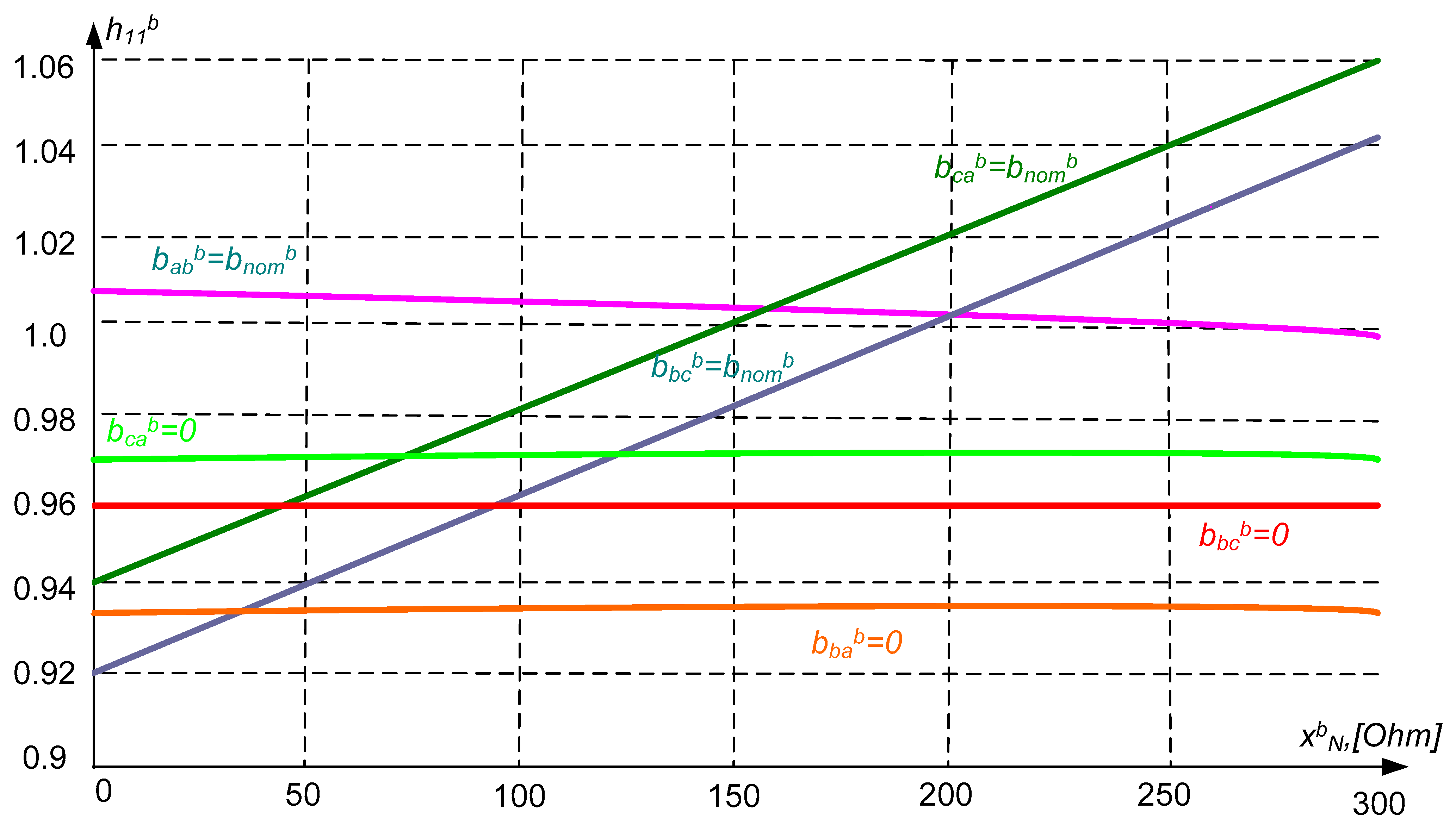
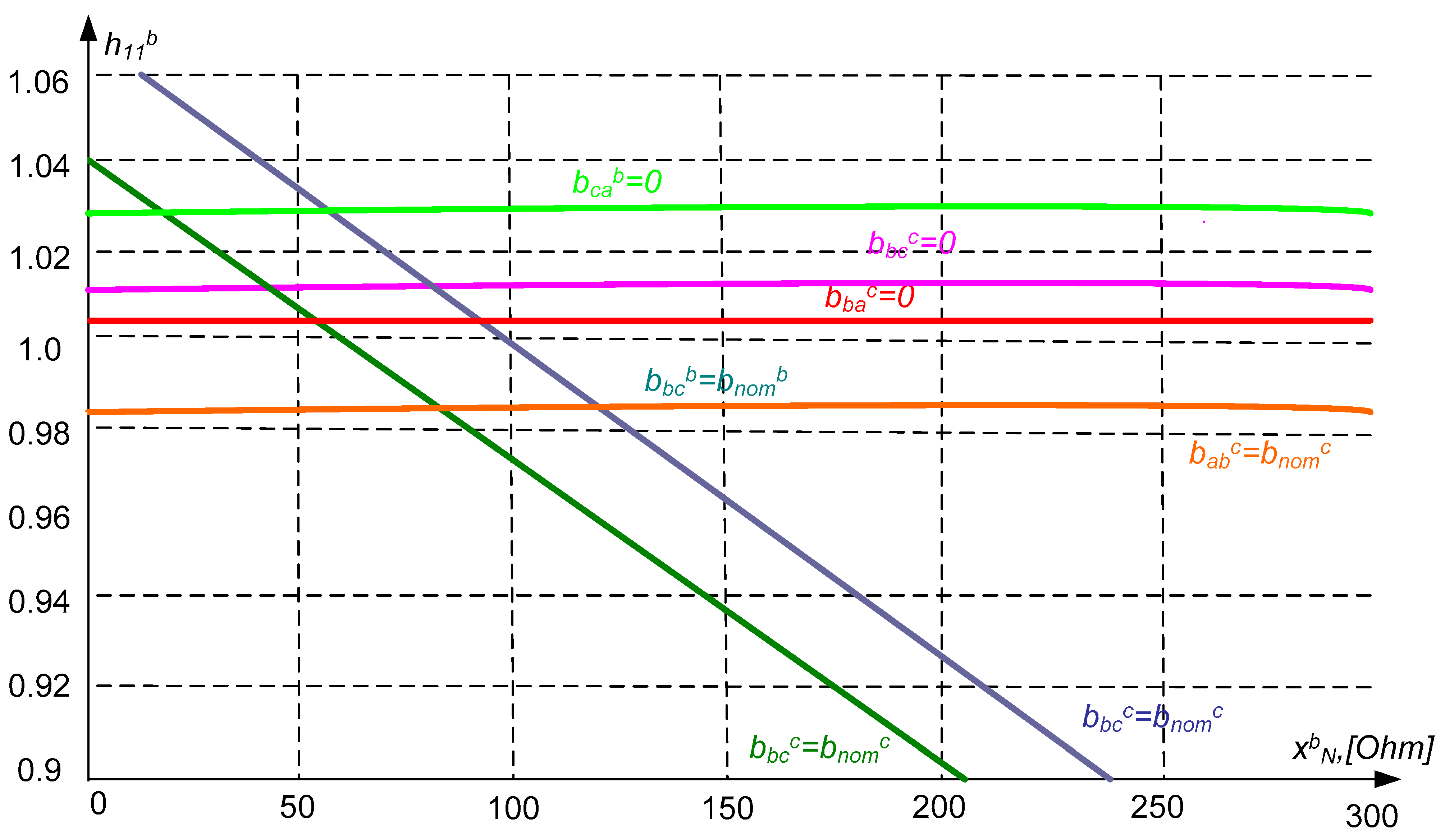
. They correspond to the fulfillment of conditions (5). Corresponding expressions that determine these connections at the STC in phase A are given below:
b a b b ~ = 0 , h 11 e = b L 11 e b L 11 ~ ; b a b b ~ = b n o m ~
h 11 e = b n o m ~ ( b L 11 b + b L 12 b + b L 13 b ) + ( b L 11 b + b n o m ~ ) b N b b n o m ~ ( b L 11 ~ + b L 21 ~ + b L 31 ~ ) + b L 11 ~ b N e
b b c b ~ = 0 , h 11 e = b L 12 e b L 21 ~ ; b b c b ~ = b n o m ~
h 11 e = b n o m ~ ( b L 11 e ~ + b L 12 b + b L 13 b ) + b L 12 e ~ b N e b n o m ~ ( b L 11 ~ + b L 21 ~ + b L 31 ~ ) + b L 21 ~ b N e
b c a b ~ = 0 , h 11 e = b L 13 e b L 31 ~ ; b c a b ~ = b n o m ~
h 11 e = b n o m ~ ( b L 11 e + b L 12 b + b L 13 b ) + b L 13 e b N e b n o m ~ ( b L 11 ~ + b L 21 ~ + b L 31 ~ ) + b L 31 ~ b N e
b a b e ~ = 0 , h 11 e = b L 11 e ~ b L 31 e ~ ; b a b e ~ = b n o m ~
h 11 e = b n o m ~ ( b L 11 ~ + b L 12 ~ + b L 13 ~ ) + b L 11 ~ b N e b n o m ~ ( b L 11 e + b L 11 e + b L 11 e ) + ( b n o m ~ + b L 11 e ) b N e
b b c e ~ = 0 , h 11 e = b L 12 e ~ b L 12 e ; b b c e ~ = b n o m ~
h 11 e = b n o m ~ ( b L 11 ~ + b L 12 ~ + b L 13 ~ ) + b L 12 ~ b N e b n o m ~ ( b L 11 e + b L 12 e + b L 13 e ) + b L 12 e b N e
b c a e ~ = 0 , h 11 e = b L 13 e ~ b L 13 e ; b c a e ~ = b n o m ~
h 11 e = b n o m ~ ( b L 11 ~ + b L 12 ~ + b L 13 ~ ) + b L 13 ~ b N e b n o m ~ ( b L 11 e + b L 12 e + b L 13 e ) + b L 13 e b N e
According to the above expressions and Figure 2, the dependences of h 11 e on x N e are plotted meeting the following conditions: b a b b ~ = 0 , b a b b ~ = b n o m ~ , b b c b ~ = 0 b b c b ~ = b n o m ~ , b c a b ~ = 0 , b c a b ~ = b n o m ~ . The desired region of the parameter h 11 e on x N e corresponding to the fulfillment of the inequalities b n o m ~ b ~ a b b , b ~ b c b , b ~ c a b 0 is shaded in Figure 2. It is limited by lines parallel to the ordinate axis. It can be seen that in this case, the region is constrained inside the curves b a b b ~ = b n o m b ~ , b c a e ~ = 0 , b b c b ~ = b n o m ~ . The same lines mark the region in Figure 3. The parameter h 11 e on x N e corresponds to the fulfillment of the conditions b ~ n o m e b ~ a b e , b ~ b c e , b ~ c a e 0 .
If both regions have a common range of variation of the parameter h 11 e , then it is possible to carry out full compensation of the feeding current of the arcs at phase A of the line at physically realizable parameters of the STC. The results presented in Figure 2 and Figure 3 mark with bold lines the region of the parameters h 11 e , x N b and h 11 e , x N b , corresponding to the simultaneous fulfillment of conditions (5).
Let us take any values h 11 e , x N b , x N e belonging to these regions. Then, it were unambiguously calculated by expressions (6) of physically realizable conductivities b a b b ~ , b b c b ~ , b c a b ~ , b a b e ~ , b b c e ~ , b c a e ~ , satisfying the conditions of full compensation of currents arc feeding at the ends of phase A of the line.
Similarly, the ranges of the parameters h 22 e , x N b and h 22 e , x N e , as well as h 33 e , x N b and h 33 e , x N e can be determined. It meets the conditions of full compensation of the secondary arc on phases B and C of the line with physically realizable primary parameters of the STC.
Obviously, it is advisable to choose the permissible values of the parameters h 11 e , h 22 e , h 33 e , x N b , x N e in such a way that the values x N b , x N e do not depend on the switched-off phase of the line. In this case, there is no need for the switching of the reactors included in the neutral of the STC transformers. It depends on the phase of the line the short circuit occurred in. With regard to the line under consideration, the following values of these parameters can be selected: h 11 e = h 22 e = h 33 e = 1 , x N b = x N e = 240 Ω.
After determining the permissible values of these quantities, it is not difficult to determine the corresponding values of the equivalent conductivities of the STC. Then, the values of the controlled conductivities meet the conditions for full compensation of the arc feed currents at the short circuit at the ends of the line. The primary conductivities STC b a b , b b c , b c a are defined in terms of b a b ~ , b b c ~ , b c a ~ as follows:
b a b = b a b ~ 1 + x T b a b ~ ; b b c = b b c ~ 1 + x T b b c ~ ; b c a = b c a ~ 1 + x T b c a ~
The values of the equivalent parameters of the STC referred to the equivalent nominal conductivity b n o m ~ and the primary parameters referred to the nominal primary conductivity of the STC b n o m are given in Table 2.
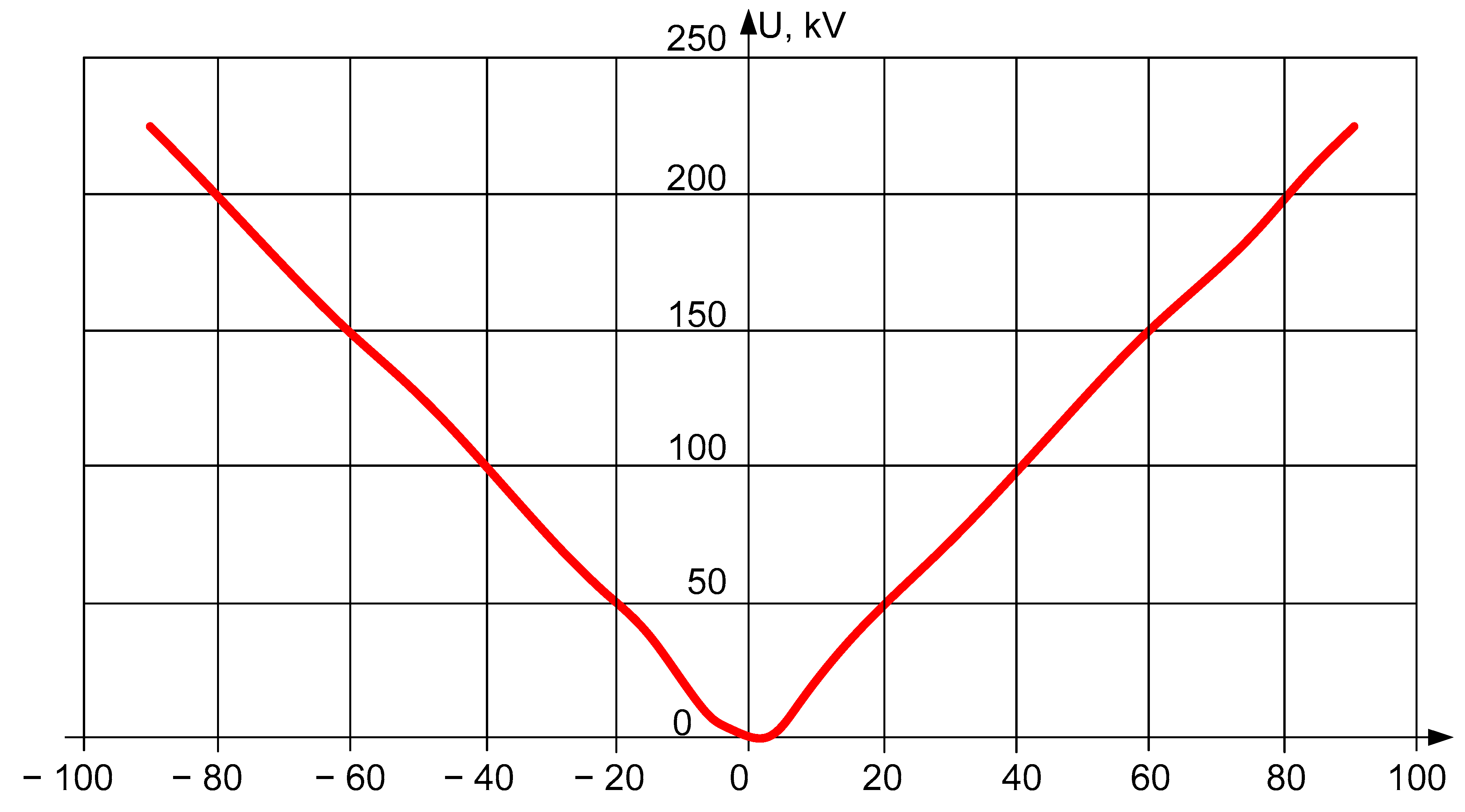
Calculations of the voltages recovering on the disconnected phase of the line after the extinction of the feeding arc show that these voltages, when the conditions for full compensation of the feeding arc at the ends of the overhead line are fulfilled, practically do not depend on the disconnected phase of the line and on the direction of power transmission. They coincide with each other at the beginning and end of the line.
The difference between the values of the recovering voltages at a certain fixed value of the angle b, both in phases and in the place of determination on the line, is less than 1%. The dependence of the restoring voltage in the line on the phase angle between the voltages on the buses of the starting and receiving substation b is shown in Figure 4. If it follows the range of variation of angle 6 from 0 to ±90°, the recovery voltage does not exceed 0.3 Uf. At very low values of the arc feeding currents, this circumstance determines the reliable and fast extinction of the feeding arc.
Calculations of the currents in the disconnected phase of the line have shown that their values do not exceed 5% of the current value during transmission through the natural power line. With such small values of currents and voltages on the disconnected phase of the overhead line, their influence on the mode of undamaged phases can be neglected. With phase-by-phase control of the STC for extinguishing the recharge arc, the asymmetric conductivity of the STC generates additional negative sequence currents. Their values do not exceed 30% of the rated phase current of the STC. According to the calculations, these currents lead to an insignificant (no more than 8%) increase in the negative sequence currents and voltages at the ends of the open-phase line. This does not create additional difficulties in the operation of relay protection devices and generators during the current-free pause of the SPAR.
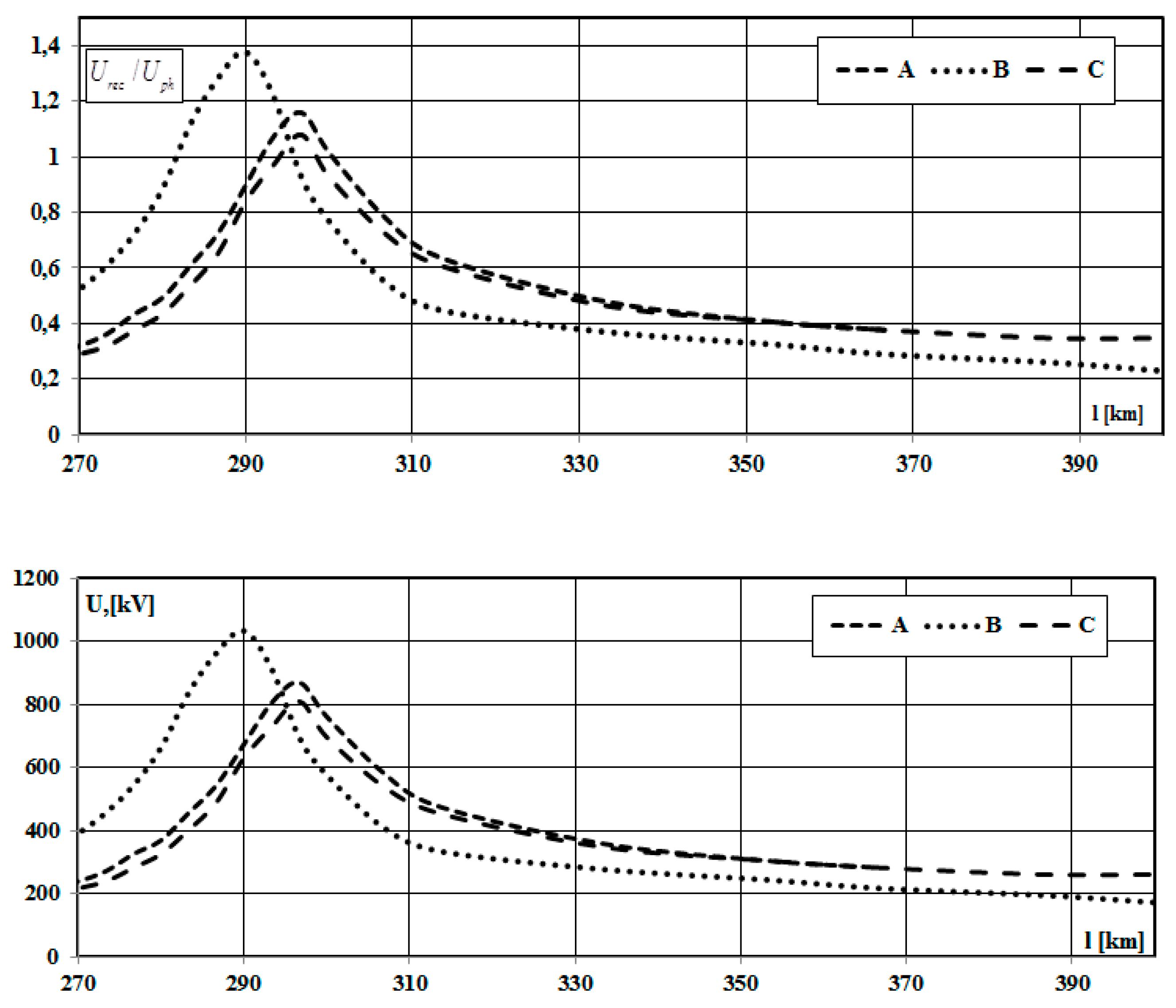
To check the adequacy of the model, the dependence of the restored voltage on the short-circuit location was chosen as a criterion (Figure 5). Applying this criterion, the location of the short circuit can also be accurately determined. The overvoltages reach maximum values at this location.
From the graphs in Figure 5, we can draw conclusions at which line lengths we must take into account the influence of longitudinal asymmetry when choosing the inductive resistance, i.e., take into account the dependence of the mode parameters on the location of the damaged phase. Based on the chart in Figure 5, we can also say that the largest values of the multiplicity of overvoltages will take place in phase B.

V Comparative Analysis of the Efficiency of STC and Compensation Reactor

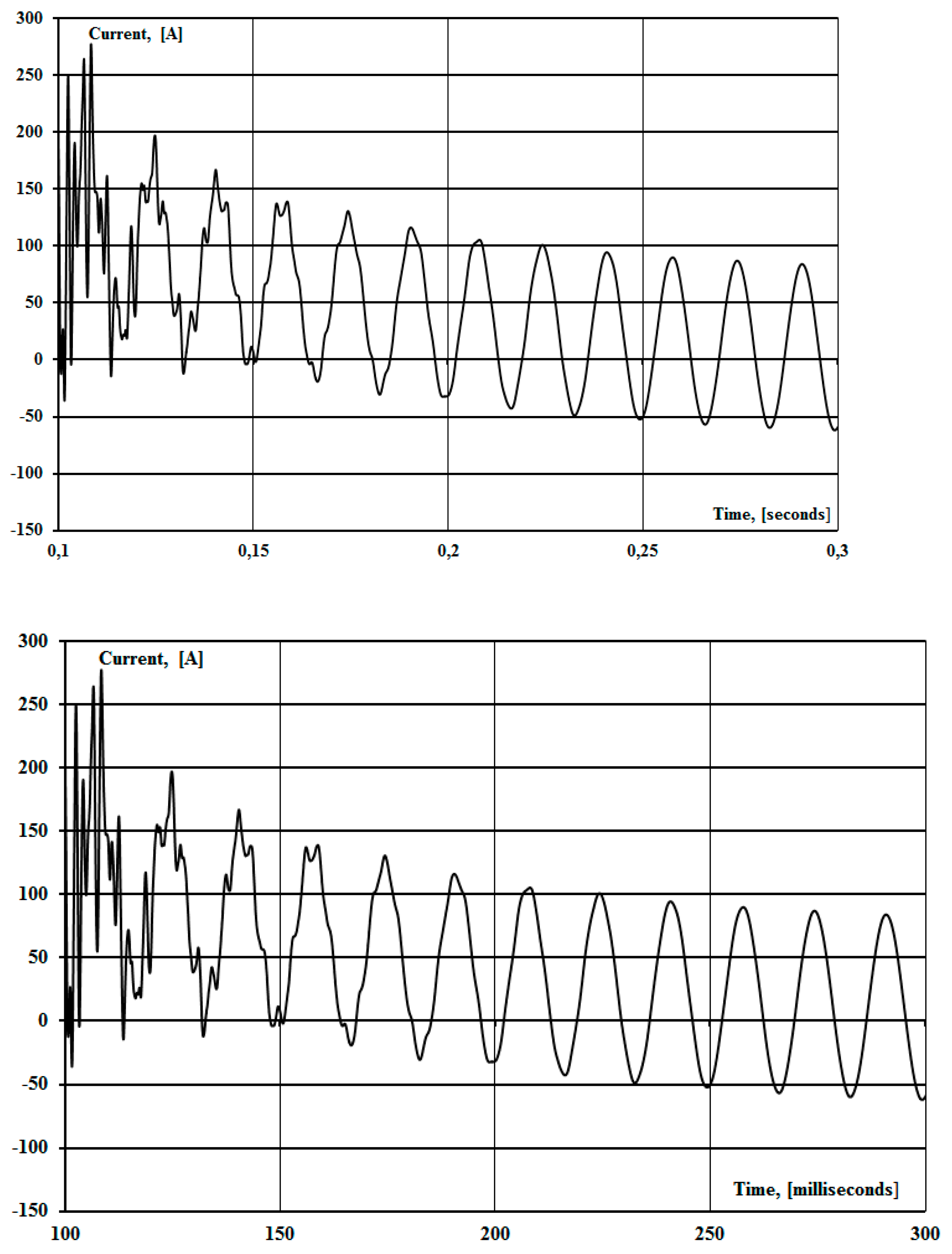
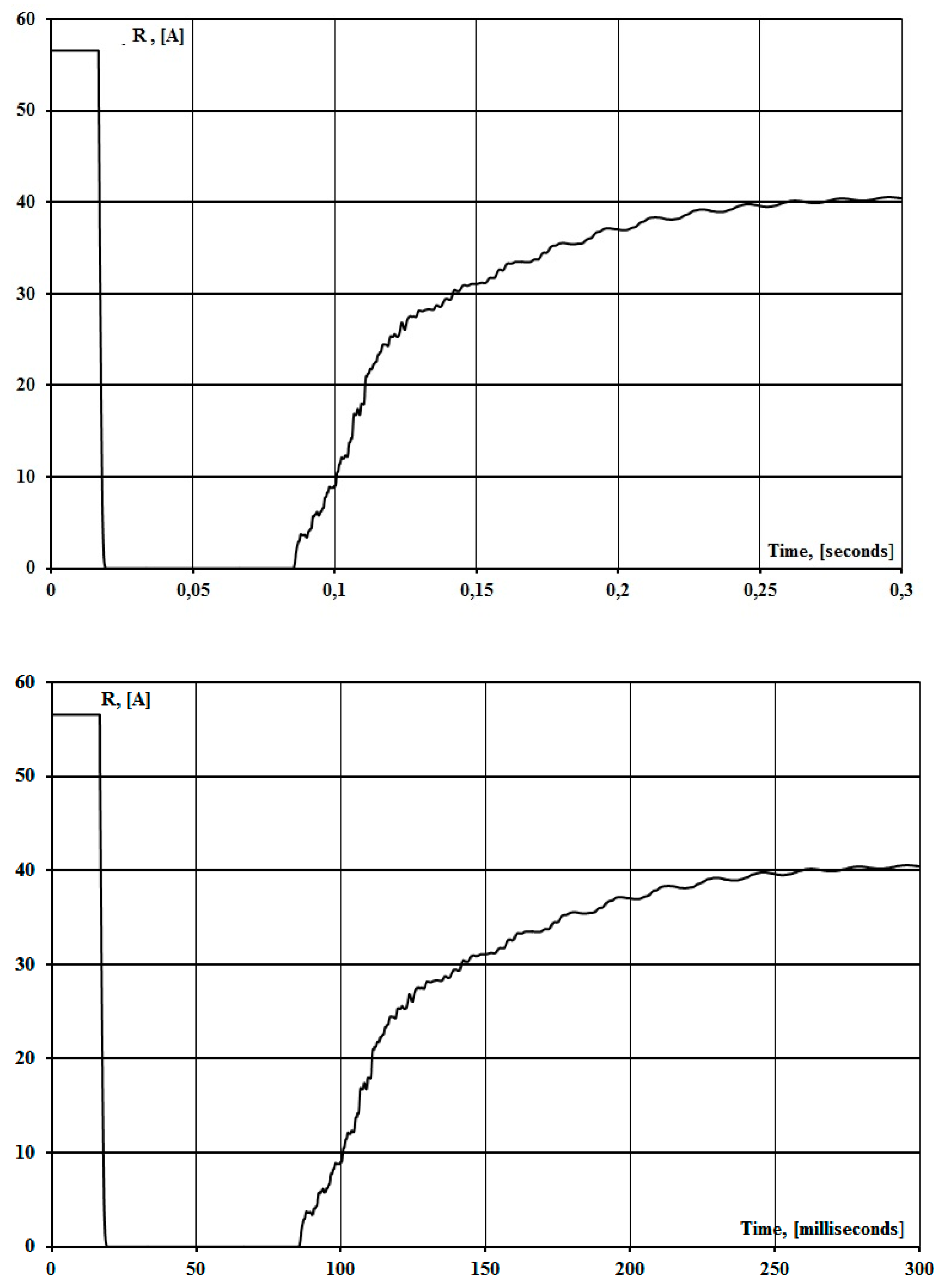
The paper considers the case of incorrect selection of the resistance of the compensation reactor, which leads to an unsuccessful cycle of operation of the SPAR due to non-extinguishing of the repeated arc (Figure 6, Figure 7 and Figure 8). Figure 6 shows the arc current at the arc short circuit. In Figure 6, the moment of operation of the SPAR occurs at 0.075 s. After the SPAR, the current of the repeated arc will receive power from the disconnected phases, which is shown in Figure 8. The value of the re-arc current exceeds the maximum allowable and leads to inefficiency of the operation cycle of the SPAR.
The resistance of the repeated arc in the pause of SPAR is shown in Figure 8 and is described by the following expression:
R a r c = R 0 e k I a r c
where I a r c is the current value of the arc current (A), R 0 ,   k are the arc parameters.
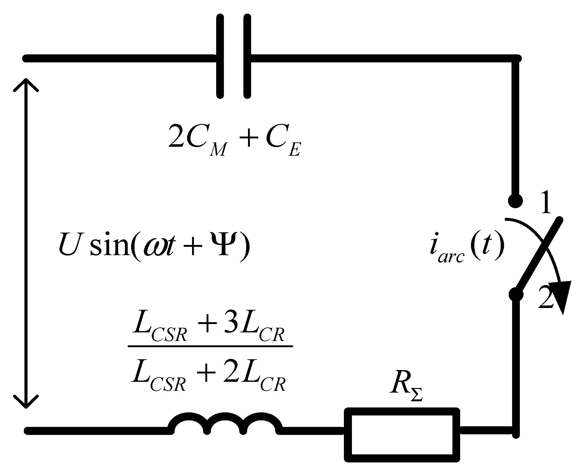
The scheme of substitution during the implementation of the SPAR is shown in Figure 9. 2 C M is the interphase capacitance of disconnected phases, C E is the capacitance between the phase and ground of the disconnected phase. L C S R is CSR inductance, L C R is CR inductance, and R Σ is the total active resistance of the disconnected phase.
After solving the differential equations, the expression for the instantaneous value of the repeated arc in the implementation of the SPAR is obtained:
i a r c ( t ) = U a r c Z a r c sin ( ω t + α φ k ) + i a r c ( 0 ) e t / T
where U a r c is the arc voltage; R a r c is the arc resistance, ω is angular velocity; T is the constant of the attenuation time of the circuit from Figure 10, i a r c ( t ) is the initial value of the arc current; α is the angle between the horizontal and the voltage vector; φ k is arc resistance argument.
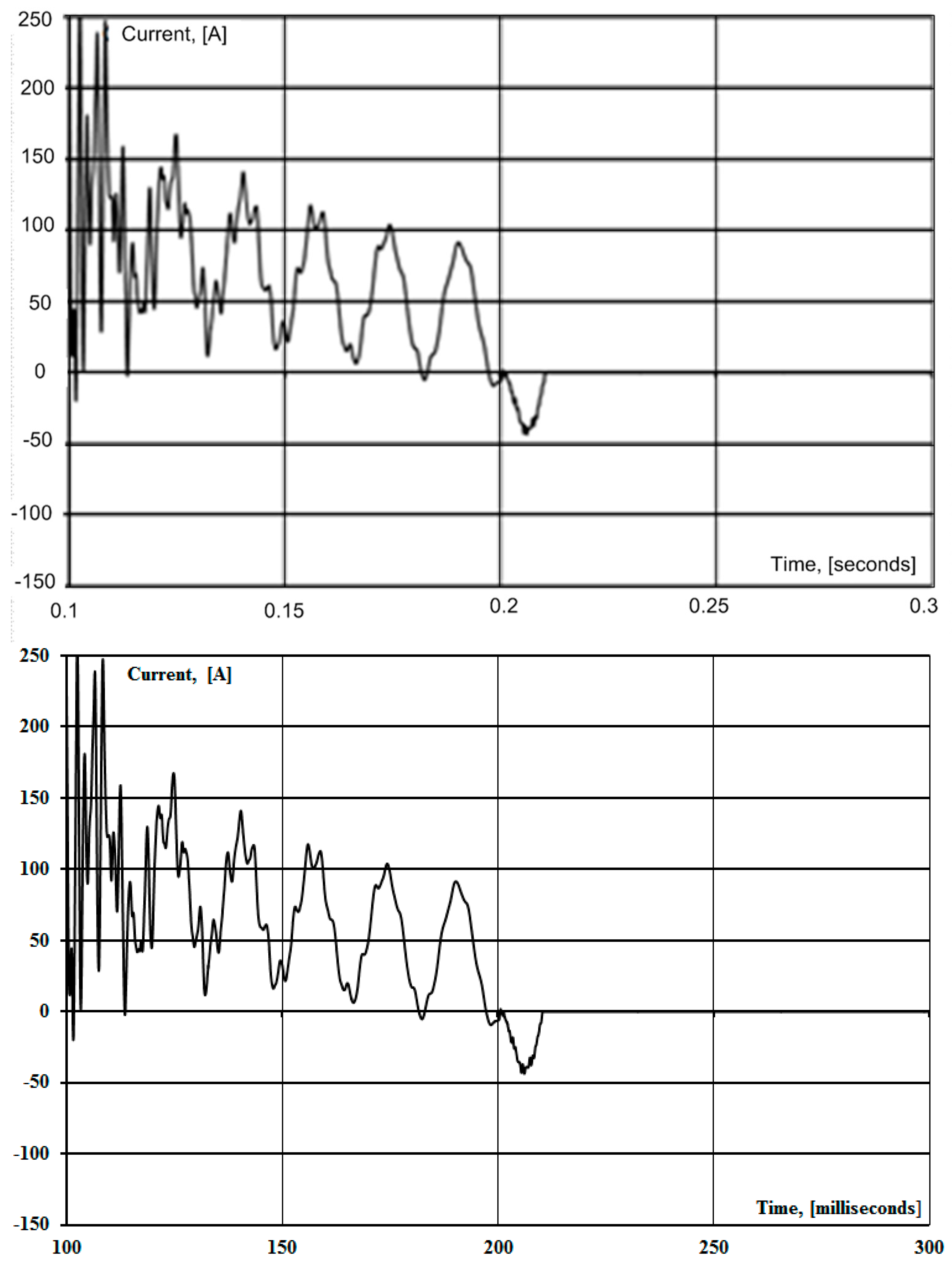
Figure 10 and Figure 11 show the current and resistance of the feed arc during the implementation of STC at 0.2 s. As can be seen from Figure 10 and Figure 11, re-arc is effectively extinguished in STC by suppression of the aperiodic component.
In the case of a single-phase short circuit in ultra-high-voltage lines, after the phase is switched off on both sides by circuit breakers, the secondary arc initiates. It is caused by the electrostatic and electromagnetic components of the disconnected phases. It may exist for a long time, and it is able to perform suppression of the aperiodic and sinusoidal components of the re-arc current during the implementation of the SPAR cycle. Further research will be aimed at the use of automatic phase shunting in order to reduce the characteristics of the aperiodic component of the current during the switching of ultra-high-voltage power lines [31].

5. Discussion

When placing static thyristor compensators at both ends of the transmission line, in principle, almost complete compensation of the secondary arc is satisfied at a short circuit anywhere in the line. Opening the triangle of the secondary windings of the STC transformer during the pause of the SPAR allows for the compensation of the secondary arc at technically permissible values of the reactance of the reactors included in the neutral of the STC transformers. The voltages on these neutrals are on the contacts of the switches that open the secondary windings of the transformers. It depends only on the disconnected phase of the line. The developed technique makes it possible to determine in advance the values of the primary conductivities of the STC and the corresponding angles of control of the thermistor switches. This satisfies almost complete compensation of the secondary arc at any point of the line.
A distinctive feature of the STC used on extra-high-voltage transmission lines is the need to connect it directly to the line in order to perform the function of a shunt reactor—to reduce overvoltage and not only switching. It is similar when the idle line is turned on and the compensation arc feeds current during the pause of the SPAR.

6. Conclusions

The invention relates to electrical engineering and can be used on high-voltage power lines equipped with single-phase automatic reclosing devices. The purpose of the STC is to improve the reliability of the SPAR implementation. The capacitive resistance is introduced to solve this problem. It is implemented into the cut of the low voltage winding of the power transformer of the static thyristor compensator to compensate for the capacitances in the line between the disconnected and non-disconnected phases as well as active resistance. It reduces the decay time of the aperiodic component of the arc-feeding current. This allows us to increase the proportion of success.
A mathematical model of a compensated power transmission line is proposed. It is based on the use of matrix n-poles, which makes it possible to model stationary power transmission modes in detail, including the SPAR mode. A mathematical model of three-phase power transmission has been created using phase coordinates for the analysis of complex asymmetric modes. Physically interpreted simplified models are proposed for three-phase lines to study the resonant overvoltages and currents of the feeding arc in non-full-phase circuit SPAR.
The concept and method of controlled SPAR requires the controlled reactive element and control algorithms in the cycle of no-current pause. This provides an optimal flow of all stages of emergency mode and minimizes no-current pause.
The paper evaluates a method that makes it possible to reduce the duration of the existing pause of the SPAR (specifically for the conditions of single-phase damage to the overhead line). It is the minimum possible under the conditions of restoration of the insulating gap. The logic of the executive bodies works in accordance with the conditions for the elimination of single-phase short circuits. Each device is adapted to the actual modes of the main electrical networks of Ukraine.
The directions correspond to actual modes of the leading electrical networks in Ukraine, specifically high-voltage transmission lines [30]. The results of this digitalization can lead to future research. Implementation of the obtained results in Enterprise Asset Management based on IBM MAXIMO technology just started to be used in Ukrainian electric networks [32].

Author Contributions

Conceptualization, M.B. and V.K.; methodology, O.R. and V.K.; validation, M.B. and V.K.; formal analysis, M.B., O.R. and V.K.; investigation, V.K., M.B. and O.R.; resources, M.B., O.R. and V.K.; writing—original draft preparation, V.K., M.B. and O.R.; writing—review and editing, M.B. and V.K. All authors have read and agreed to the published version of the manuscript.

Funding

This study was supported by projects 23-PKVV-UM-011, 23-PKVV-011, and MSCA4Ukraine ID number 1233365.

Data Availability Statement

The data presented in this study are available on request from the corresponding author.

Conflicts of Interest

The authors declare no conflict of interest. The funders had no role in the design of the study, in the collection of data, or analyses.

References

  1. Zheng, T.; Liu, X. Analysis of Power Regulation of Magnetically Controlled Shunt Reactor and Its Impacts on Protection. In Proceedings of the 2020 IEEE Power & Energy Society General Meeting (PESGM), Montreal, QC, Canada, 2–6 August 2020; pp. 1–5. [Google Scholar] [CrossRef]
  2. Avila-Montes, J.; Melgoza, E.; Olivares-Galvan, J.C. Analysis of a virtual gap reactor as shunt compensation device. In Proceedings of the 2016 IEEE International Autumn Meeting on Power, Electronics and Computing (ROPEC), Ixtapa, Mexico, 9–11 November 2016; pp. 1–5. [Google Scholar] [CrossRef]
  3. Zheng, T.; Zhao, Y.J.; Jin, Y.; Chen, P.L.; Zhang, F.F. Design and analysis on the turn-to-turn fault protection scheme for the control winding of magnetically controlled shunt reactor. IEEE Trans. Power Deliv. 2015, 30, 967–975. [Google Scholar] [CrossRef]
  4. Chen, X.; Chen, B.; Tian, C.; Yuan, J.; Liu, Y. Modeling and Harmonic Optimization of a Two-Stage Saturable Magnetically Controlled Reactor for an Arc Suppression Coil. IEEE Trans. Ind. Electron. 2012, 59, 2824–2831. [Google Scholar] [CrossRef]
  5. Sun, Q.; Lin, F.; Jiang, R.; Wang, F.; Chen, S.; Zhong, L. A novel adaptive single-phase reclosure scheme based on improved variational mode decomposition and energy entropy. Int. J. Electr. Power Energy Syst. 2020, 118, 105771. [Google Scholar] [CrossRef]
  6. Xie, X.; Huang, Z.; Fan, X.; Tang, T. Adaptive single-phase auto-reclosing scheme based on the moving average filter-quadrature signal generator for transmission lines with shunt reactors. Electr. Power Syst. Res. 2023, 223, 109545. [Google Scholar] [CrossRef]
  7. Arefaynie, A.D.; Saad, M.; Kim, C.-H. Detection of secondary arc extinction and auto-reclosing in compensated AC transmission lines based on machine learning. Electr. Power Syst. Res. 2023, 223, 109588. [Google Scholar] [CrossRef]
  8. Kuchanskyy, V.; Zaitsev, I.O. Corona Discharge Power Losses Measurement Systems in Extra High Voltage Transmissions Lines. In Proceedings of the 2020 IEEE 7th International Conference on Energy Smart Systems (ESS), Kyiv, Ukraine, 12–14 May 2020; pp. 48–53. [Google Scholar] [CrossRef]
  9. Kuznetsov, V.G.; Tugai, Y.I. Tugai Improving reliability and efficiency of bulk electrical networks. Proc. Inst. Electrodyn. Natl. Acad. Sci. Ukr. 2009, 23, 110–117. [Google Scholar]
  10. Han, B.; Ban, L.; Xiang, Z.; Zhang, Y.; Zheng, B. Analysis on Strategies of Suppressing Secondary Arc Current in UHV system with Controllable Shunt Reactors. In Proceedings of the IEEE International Conference on Power System Technology (POWERCON), Wollongong, Australia, 28 September–1 October 2016; pp. 14–19. [Google Scholar]
  11. Gundebommu, S.L.; Hunko, I.; Rubanenko, O.; Kuchanskyy, V. Assessment of the Power Quality in Electric Networks with Wind Power Plants. In Proceedings of the 2020 IEEE 7th International Conference on Energy Smart Systems (ESS), Kyiv, Ukraine, 12–14 May 2020; pp. 190–194. [Google Scholar] [CrossRef]
  12. Martinich, T.; Nagpal, M.; Manuel, S. Damaging Open-Phase Overvoltage Disturbance on a Shunt-Compensated 500-kV Line. IEEE Trans. Power Deliv. 2015, 30, 412–419. [Google Scholar]
  13. Bollen, M.H.J. What is power quality? Review. Electr. Power Syst. Res. 2003, 66, 5–14. [Google Scholar] [CrossRef]
  14. Wenjuan, Z.; Tolbert, L.M. Survey of reactive power planning methods. In Proceedings of the 2005 PES General Meeting, San Francisco, CA, USA, 16 June 2005; pp. 1430–1440. [Google Scholar]
  15. Chengxi, L.; Nan, Q.; Bak, C.L.; Yini, X. A hybrid optimization method for reactive power and voltage control considering power loss minimization. In Proceedings of the 2015 IEEE Eindhoven PowerTech, Eindhoven, The Netherlands, 29 June–2 July 2015; pp. 1–6. [Google Scholar]
  16. Herman, L.; Papič, I. Optimal control of reactive power compensators in industrial networks. In Proceedings of the 14th International Conference on Harmonics and Quality of Power (ICHQP), Bergamo, Italy, 26–29 September 2010. [Google Scholar]
  17. Eajal, A.A.; El-Hawary, M.E. Optimal capacitor placement and sizing in distorted radial distribution systems. Part II: Problem formulation and solution method. In Proceedings of the 14th International Conference on Harmonics and Quality of Power (ICHQP), Bergamo, Italy, 26–29 September 2010. [Google Scholar]
  18. Lukomski, R.; Wilkosz, K. Optimization of reactive power flow in a power system for different criteria: Stability problems. In Proceedings of the 8th International Symposium on Advanced Topics in Electrical Engineering, Bucharest, Romania, 23–24 May 2013; pp. 1–6. [Google Scholar]
  19. Abdou, A.A.; Kamel, S.; Jurado, F.; El-Sattar, S.A. Voltage stability maximization of power system using TLBO optimizer and NEPLAN software. In Proceedings of the Power Systems Conference (MEPCON) 2017 Nineteenth International Middle East, Cairo, Egypt, 19–21 December 2017; pp. 1122–1127. [Google Scholar]
  20. El Refaie, H.B.; Negm, E.; El Razik, M.A.; Negm, T.S. Developed model and simulation of primary and secondary arc fault on transmission lines using MATLAB. In Proceedings of the 2017 Nineteenth International Middle East Power Systems Conference (MEPCON), Cairo, Egypt, 19–21 December 2017; pp. 965–970. [Google Scholar] [CrossRef]
  21. Cong, H.; Li, Q.; Xing, J.; Siew, W.H. Modeling Study of the Secondary Arc with Stochastic Initial Positions Caused by the Primary Arc. IEEE Trans. Plasma Sci. 2015, 43, 2046–2053. [Google Scholar] [CrossRef]
  22. Liu, Y.; Wen, J. Analysis of the Factors Affecting Secondary Arc Current on UHV Transmission Lines. In Proceedings of the 2009 International Conference on Energy and Environment Technology, Guilin, China, 16–18 October 2009; pp. 69–72. [Google Scholar] [CrossRef]
  23. Xu, Z.Y.; Zhang, X.; Yan, X.Q.; Wen, A. Optimal compensating scheme for limiting secondary arc current of 1000-kV UHV short parallel lines. IET Generat. Transmiss. Distrib. 2012, 6, 1235–1242. [Google Scholar] [CrossRef]
  24. Li, Q.; Sun, Q.; Lou, J.; Zhang, L.; Cong, H. Research on a novel suppressing methodology for secondary arc extinction based on an impedance paralleled to line circuit breaker. Int. Trans. Elect. Energy Syst. 2014, 24, 281–296. [Google Scholar] [CrossRef]
  25. Goda, Y.; Matsuda, S.; Inaba, T.; Ozaki, Y. Forced extinction characteristics of secondary arc on UHV (1000 kV class) transmission lines. IEEE Trans. Power Del. 1993, 8, 1322–1330. [Google Scholar] [CrossRef]
  26. Xu, Z.; Yan, X.; Zhang, X.; Wen, A. Compensating scheme for limiting secondary arc current of 1000 kV ultra-high voltage long parallel lines. IET Generat. Transmiss. Distrib. 2013, 7, 1–8. [Google Scholar] [CrossRef]
  27. Inguimbert, V.; Sarrail, D.; Mateo-Velez, J.C.; Reulet, R.; Levy, L.; Boulay, F.; Payan, D. Electrostatic discharge and secondary arcing on solar array—Flashover effect on arc occurrence. IEEE Trans. Plasma Sci. 2008, 36, 2404–2412. [Google Scholar] [CrossRef]
  28. He, Y.; Song, G.; Cao, R.J. Test research of secondary arc in 1000 kV UHV double-circuit transmission lines. CSEE 2011, 31, 138–143. [Google Scholar]
  29. Li, Q.; Cong, H.; Sun, Q.; Xing, J.; Chen, Q. Characteristics of secondary AC arc column motion near power transmission-line insulator string. IEEE Trans. Power Del. 2014, 29, 2324–2331. [Google Scholar] [CrossRef]
  30. Wang, S.; Cong, H.; Han, D.; Pan, H.; Li, Q. Study on the Influence of Lightning Current on Space-Time Evolution of Secondary Arc. In Proceedings of the 2020 IEEE 3rd Student Conference on Electrical Machines and Systems (SCEMS), Jinan, China, 4–6 December 2020; pp. 528–533. [Google Scholar]
  31. Belik, M.; Kuchanskyy, V.; Yuri, L.; Rubanenko, O. Optimal Value Determining Method of Parameters Compensating Devices of Bulk Electric Networks. In Proceedings of the 2022 IEEE 8th International Conference on Energy Smart Systems (ESS), Kyiv, Ukraine, 12–14 October 2022; pp. 63–68. [Google Scholar] [CrossRef]
  32. EY Ukraine Digital and Ukrenergo Win Award for Best Maximo Data Governance at MaximoWorld 2023. Available online: https://www.ey.com/en_ua/news/2023/08/ey-ukraine-digital-ukrenergo-best-maximo-data-governance-maximoworld-2023 (accessed on 17 August 2023).
Figure 1. Schematic diagram of power transmission.
Energies 16 06880 g001
Figure 2. Determination of the regions of free parameters that meet the conditions of physical realizability of the primary parameters of the STC when phase A of the line is disconnected in case x N b .
Energies 16 06880 g002
Figure 3. Determination of the regions of free parameters that meet the conditions of physical realizability of the primary parameters of the STC when phase A of the line is disconnected in case x N e .
Energies 16 06880 g003
Figure 4. Recovering voltage on the line after extinguishing the secondary arc.
Energies 16 06880 g004
Figure 5. Voltages of the disconnected phase of the line when changing the length.
Energies 16 06880 g005
Figure 6. Arc current at arc short circuit on EHV transmission line.
Energies 16 06880 g006
Figure 7. The effectiveness of STC for prevention the long-term existence of a secondary arc.
Energies 16 06880 g007
Figure 8. The effectiveness of STC in preventing abnormal resonant overvoltages.
Energies 16 06880 g008
Figure 9. Substitution scheme for the replacement of the disconnected phase in SPAR.
Energies 16 06880 g009
Figure 10. Effectiveness of STC application in preventing long-term re-arc existence.
Energies 16 06880 g010
Figure 11. The effectiveness of the use of STC in preventing the long-term existence of the feed arc with values exceeding the maximum allowable values.
Energies 16 06880 g011
Table 1. Conditions for full compensation of the secondary arc at a short circuit at the ends of the line for the disconnected phase (A, B, C).
ABC
b 12 b = h 11 e b L 21 ~ b L 12 b b 13 b = h 11 e b L 31 ~ b L 13 b b 11 b = h 11 e b L 31 ~ b L 11 b b 12 e = b L 12 ~ / h 11 e b L 12 e b 13 e = b L 13 ~ / h 11 e b L 13 e b 11 e = b L 11 ~ / h 11 e b L 11 e b 12 b = h 22 e b L 12 ~ b L 12 b b 23 b = h 22 e b L 32 ~ b L 23 b b 22 b = h 22 e b L 22 ~ b L 22 b b 12 e = b L 21 ~ / h 22 e b L 12 e b 23 e = b L 23 ~ / h 22 e b L 23 e b 22 e = b L 22 ~ / h 22 e b L 22 e b 13 b = h 33 e b L 13 ~ b L 13 b b 23 b = h 22 e b L 23 ~ b L 23 b b 33 b = h 33 e b L 33 ~ b L 33 b b 12 e = b L 31 ~ / h 33 e b L 13 e b 23 e = b L 32 ~ / h 33 e b L 33 e b 33 e = b L 33 ~ / h 33 e b L 33 e
Table 2. Equivalent parameters of the STC.
ParametersParameter Values at Deviation Phases
(A, B, C)
ABC
b 11 b 0.8799081430.5213
b 22 b 0.83190.86680.2468
b 22 b 0.54690.23430.8572
b 12 b −0.1184−0.1214−0.0199
b 13 b −0.0741−0.0295−0.0772
b 23 b −0.0698−0.0317−0.0349
b 11 e 0.85770.20830.5720
b 22 e −0.22060.86440.8401
b 33 e 0.54070.81710.8769
b 12 e −0.312−0.0281−0.0692
b 13 e −0.0805−0.263−0.0773
b 23 e −0.0185−0.1223−0.1189
b a b b 10.91950.5389
b b c b 0.93710.99680.2360
b c a b 0.56450.22300.9919
b a b e 0.99280.19690.5943
b b c e 0.20950.996870.9428
b c a e 0.56230.92391.000
Disclaimer/Publisher’s Note: The statements, opinions and data contained in all publications are solely those of the individual author(s) and contributor(s) and not of MDPI and/or the editor(s). MDPI and/or the editor(s) disclaim responsibility for any injury to people or property resulting from any ideas, methods, instructions or products referred to in the content.

