Abstract
Sustainable aviation fuels (SAF) are needed in large quantities to reduce the negative impact of flying on the climate. So-called power-to-liquid (PtL) plants can produce SAF from renewable electricity, water, and carbon dioxide. Reactors for these processes that are suitable for flexible operation are difficult to manufacture. Metal 3D printing, also known as additive manufacturing (AM), enables the fabrication of process equipment, such as chemical reactors, with highly optimized functions. In this publication, we present an AM reactor design and conduct experiments for Fischer-Tropsch synthesis (FTS) under challenging conditions. The design includes heating, cooling, and sensing, among others, and can be easily fabricated without welding. We confirm that our reactor has excellent temperature control and high productivity of FTS products up to 800 kgC5+ mcat−3 h−1 (mass flow rate of hydrocarbons, liquid or solid at ambient conditions, per catalyst volume). The typical space-time yield for conventional multi-tubular Fischer-Tropsch reactors is ~100 kgC5+ mcat−3 h−1. The increased productivity is achieved by designing reactor structures in which the channels for catalyst and cooling/heating fluid are in the millimeter range. With the effective control of heat release, we observe neither the formation of hot spots nor catalyst deactivation.
1. Introduction
Sustainable aviation fuels (SAF) can significantly reduce global warming by the aviation industry until hydrogen- and battery-powered aircrafts could be available [1,2,3]. SAF are based on either biogenic feedstocks or renewable electricity, water, and carbon dioxide. In the latter case, they require less land and water and have the highest potential to reduce greenhouse gas emissions [4,5]. For their rapid deployment, it is advantageous to produce these so-called power-to-liquid (PtL) fuels in a decentralized manner. A decentralized plant has economic advantages in terms of operation if it is load flexible and has high efficiency [6]. There is an advantage in installation cost and time when compact and modular equipment is used [7].
1.1. Fischer-Tropsch Synthesis
In this study, low-temperature Fischer-Tropsch synthesis (FTS) was used because it produces the medium- to long-chain C9–C18 hydrocarbons found in kerosene [8]. This reaction takes place on a supported cobalt catalyst at temperatures of T = 200–250 °C and pressures of typically p = 20–30 bara and is highly exothermic; see Equation (1) [9]. The main products range from methane to mostly linear alkanes and 1-olefines with a carbon number higher than 50. Oxygenates are produced to some extent [10] and H2O appears as a by-product stoichiometrically linked to hydrocarbon formation according to Equation (1). Significant production of CO2 via the water-gas shift reaction is not expected for Co-based FTS [11]. Hydrocarbons with five or more carbon atoms are referred to as C5+ and are considered the main product because they are liquid or solid at ambient conditions.
The adiabatic temperature rise of the FTS reaction is immense and can lead to catalyst or reactor destruction. High temperatures affect the selectivity for the desired product as they favor methane formation [12]. Therefore, temperature control is an important function of an FTS reactor.
1.2. Compact Reactors
Traditionally, to limit the temperature rise in fixed bed reactors, either the feed or the catalyst is diluted [13]. However, this is not practical for decentralized plants where product separation should be simple, and reactors should be compact. One solution is reactors with excellent heat removal, such as liquid-cooled microstructure reactors [14]. Such reactors have complex networks of internal channels. In addition, the operating conditions and the reaction media require that the reactors be made of metal and have dense walls.
They are often made conventionally from metal sheets by milling or etching followed by diffusion bonding, or laser welding and adaptation [15]. Examples of such reactors for FTS can be found in research and early industrial adoption [12,16,17,18]. It can be deduced that the fabrication of such a reactor is a multistep process involving several sophisticated technological steps. These reactors show excellent heat removal from the reaction zone [19,20]. Therefore, it is possible to use conventional catalysts instead of composite catalysts with higher thermal conductivity [21].
Metal additive manufacturing (AM) is well-known in mechanical engineering. In the tooling industry, for example, it is praised for its ability to produce parts with conformal cooling [22]. Here, we have focused on powder bed fusion with laser beam of metals (PBF-LB/M) for the fabrication of 316L stainless steel parts. It allows design freedom beyond the limits of conventional manufacturing and simplifies the fabrication of process engineering devices. PBF-LB/M is currently used to manufacture reactors, heat exchangers, and separation equipment [23]. It is used to build almost any part that includes, for example, internal channels with complex geometries or integrated features such as porous regions or sensors [24,25].
It is used to fabricate inserts for exothermic catalytic reactions [26,27]. Fratalocchi et al., have shown that AM inserts improve heat transfer in fixed bed reactors of conventional size [28]. Our goal is to fabricate the entire reactor with AM to simplify manufacturing, to increase efficiency, and to incorporate features, as do the authors of [29,30].
2. Compact AM Reactor
The goal of this work was to demonstrate a laboratory scale reactor concept that can be scaled up to production size. The volume available for the catalyst is denoted as the volume of the reaction zone within the AM part minus the volume of internal structures. It is estimated as Vcat = 4.4 cm3. The catalyst bulk density is assumed as ρcat = 0.75 g cm−3. This section presents the design and fabrication of the device. The initial requirements for the reactor were:
- Introduction of catalyst with a particle size of dp = 50–150 µm,
- Performance of the FT reaction with undiluted catalyst and synthesis gas at H2/CO = 2.0 and Ftotal = 6 to 30 LN h−1,
- SV = F/Vcat = 1500 to 7500 h−1; τ = 1.33 to 6.67 × 10⁻⁴ h = 0.48 to 2.4 s, and
- SVmod = F/mcat = SV/ρcat = 2 to 10 LN gcat−1 h−1; τmod = 0.1 to 0.5 h gcat LN−1; the index ‘mod’ denotes that the space velocity is related to the catalyst mass.
- Efficient cooling,
- Scalability through slit design,
- Spatially resolved T measurement,
- Possibility of connection to standard laboratory equipment,
- Streamlined workflow,
- Operating pressure of 20 bara @ 250 °C, and
- Helium standard leakage rate at q < 1 × 10⁻⁸ mbar L s−1 [31].
The reactor is not intended for the measurement of data relevant for kinetic parameter estimation. It is intended as laboratory-scale proof of concept of the AM reactor concept and as a baseline for further optimization. The long-term aim are reactors for decentralized production plants.
2.1. Design
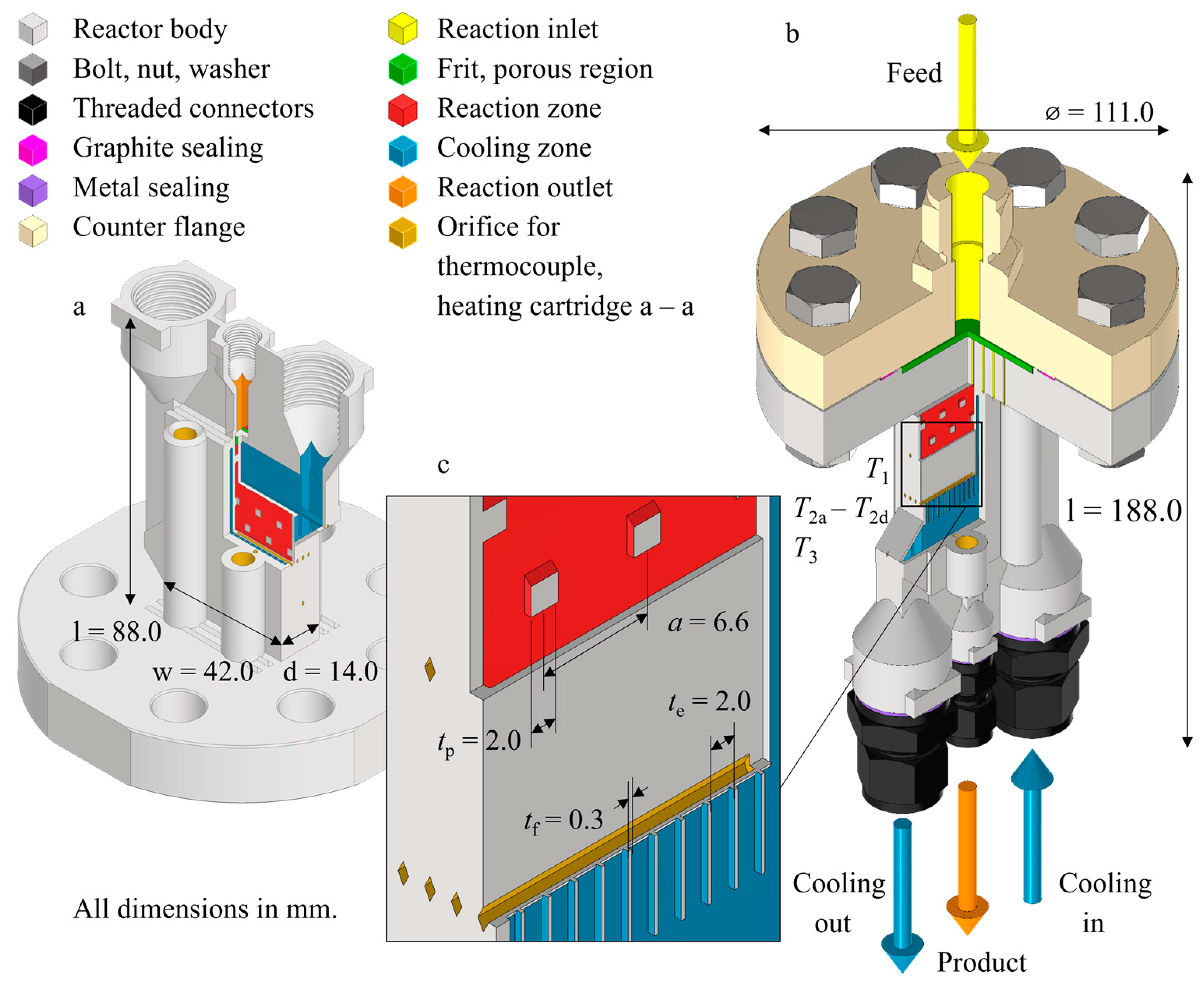
The design was performed in Autodesk Inventor 2022 and exported to standard tessellation language (STL) format. The reactor was designed as a slit reactor based on slit design elements thoroughly investigated by us, Figure 1. The slits belong alternately to the reaction zone (slits 2 and 4) and the cooling zone (slits 1, 3 and 5). The slits have a depth dslit = 1 mm, width wslit = 40 mm and length lcat = 55 mm (lcooled = 53 mm) and contain internal structures. The wall thickness is tw = 1 mm. The reaction zone contains square pins with a side length tp = 2 mm in a hexagonal arrangement with a spacing a = 6.6 mm, resulting in a void ratio of about 0.9. The ratio of the catalyst volume Vcat to the heat transfer surface Ahex is about 2000 m−1. The gas flows through from top to bottom. The cooling zone contains fins with a thickness of tf = 0.3 mm and a spacing of a = 2 mm. The thermal oil flows through from top to bottom, while the inlet and outlet are located on both sides of the reactor body, respectively. There are no fins in these areas.
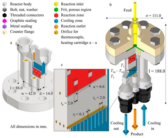
Figure 1.
Reactor with parts cut out to show internal structure. (a) Manufacturing situation. (b) Filling and operating situation. Feed flows from the reaction inlet (yellow) through the reaction zone (red) to the reaction outlet (orange), passing through porous regions (green). (c) Detailed view.
For spatially resolved temperature measurement, six horizontal thermocouple channels were placed inside the reactor, extending from the side to half the width of the device. Three channels are evenly distributed along the length of the reaction zone (l1 = 13.7; l2 = 27.5; l3 = 41.3 mm from the flange) in a wall between the reaction and cooling slits. On the length l2 there are three channels in further walls between the slits. The cross section of these channels is a rhombus at the tip. The readings of these thermocouples are referred to as T1, T2a to T2d, and T3. At the front and back of the reactor, there are two cylindrical channels each for heating cartridges and one for a thermocouple. At the top end of the reaction slits, a porous region is made together with the dense walls of the reactor. The porous region holds the catalyst in place but allows fluids from the reaction zone to pass through to the top port (G1/8” internal thread). The inlet and outlet of the cooling zone are both routed upward to ports (G1/2” internal thread) that terminate at the same level as the reaction port.
This unit complies with most design guidelines for PBF-LB/M [32], e.g., there are no overhanging surfaces with an angle to the building plane below the threshold of φ < 45°. In smaller sections, wall thicknesses below the recommendations tw = 0.26 mm ≤ 0.6 mm occur. Preliminary tests showed that abrupt termination of a partial surface (φ = 0°) should be avoided. Therefore, we added zigzag volumes on the top of the part.
2.2. Fabrication
The reactor was built using a hybrid approach. A conventionally fabricated flange plate was placed in the PBF-LB/M machine as a base for the AM part. Both parts are fused together during the fabrication process to form the monolithic reactor body as shown in Figure 1a.
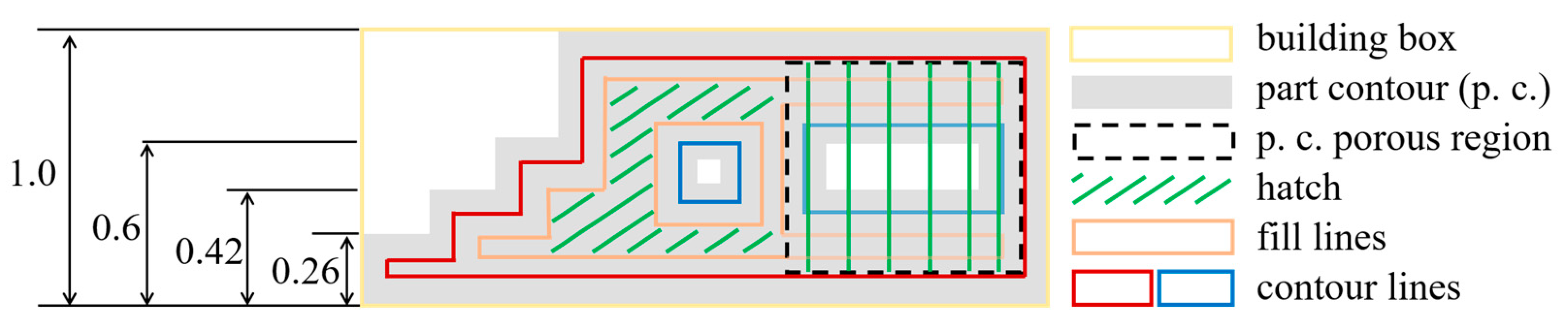
The scanning strategy for the solid walls includes hatching with a rectangular pattern and rotation between layers, and double scanning of the fill line and contour line, respectively. The scanning strategy for the porous region only consists of hatching which does not rotate [33]. Melt tracks are above one another, and the distance between two adjacent melt tracks is as small as possible, but large enough that they do not fuse together (Figure 2). Preliminary tests showed that particles with dp ≥ 100 µm are retained by the porous region. For more information, please refer to the Supplementary Information.
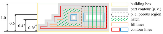
Figure 2.
Reactor scan strategy. Depending on their size, features are made with contour lines, fill lines, and hatching. A porous area can be seen on the right. It overlaps with the solid region and consists entirely of hatching.
Fabrication was performed on a DMG MORI Realizer SLM125 using 316L stainless steel powder and took 20 h, with no subsequent heat treatment required. The design of the reactor body does not require support structures, so almost no post-processing is required. The following machining operations were performed on the connections using an NC mill and manual tools: finishing and chamfering of the threads and milling of the upper level. The holes for the heating cartridge were drilled and reamed. Male threaded connections with metal gaskets (Swagelok) were connected to the reactor as shown in Figure 1b.
The reactor was thoroughly vacuum cleaned and depowdered before being rinsed with isopropanol. It was then subjected to an ultrasonic bath with water and detergent for 30 min before being dried in an oven at T = 70 °C.
3. Experimental Methods
This section describes the catalyst, the experiments for continuous Fischer-Tropsch synthesis, and the formulas used to evaluate the results. All materials used are listed in the Supplementary Information.
3.1. Catalyst
A Co-Pt-Si/γ-Al2O3 catalyst was prepared by incipient wetness co-impregnation of cobalt nitrate (Co(NO3)2·6H2O) and platinum nitrate (Pt(NO3)2). Tetraethoxysilane (C8H20SiO4) was impregnated in a following separate step on γ-Al2O3 support (Puralox SCCa 5–150), ABET = 140 m2 g−1, Vpore = 0.46 cm3 g−1, and dpore = 13.2 nm). The catalyst was dried in a rotary evaporator (80 °C, 60 min) and calcination was carried out under continuous air flow at 250 °C (ramp 2 °C min−1, 1 LN gcat−1 h−1) for 4 h. After the calcination, the catalyst was sieved, and a 50–150 µm particle size fraction was collected. The resulting catalyst had 21.4 wt% cobalt, 0.2 wt% platinum, and 1.6 wt% silicon. Platinum-promoter-assisted hydrogen reduction and silicon was added to prevent support leaching. The catalyst was supplied by VTT.
3.2. Reaction Test
With the counter flange and a preliminary polymer gasket, the He standard leak rate was determined using a PhoeniXL He leak detector (Leybold, Cologne, Germany). A pressure test with water was performed on a pressure test rig (SITEC, Maur, Switzerland). The reactor was then dried and reopened.
The original catalyst sample was sieved to dp = 100–150 µm to ensure the functionality of the AM porous region. Both reaction slits were filled with half of mcat = 3.3357 g each. Remaining space was filled with SiC with dp = 200–300 µm before a porous metal frit was added to the reactor. The counter flange was secured with a graphite gasket using eight M12 bolts. The bolts were tightened until the gasket was sufficiently compressed to t = 0.6 mm, which was checked with a feeler gauge between the flanges. The reactor was also equipped with thermocouples and heating cartridges, which were coated with thermal paste before insertion. The reactor was installed in a test rig that included: gas supply, reactor, insulation, oil thermostat, hot trap (T = 170 °C), cold trap (T = 5 °C), backpressure regulator, and online GC.
The reactor was flushed with FN2 = 200 mLN min−1. Subsequently, 10% of the N2 flow was replaced with H2 to ensure reducing conditions during high-temperature operation. The reactor was heated at a ramp of 1.5 K min−1 using the heating cartridges. At T = 400 °C it was reduced for t = 20 h at p = 1 bara with FH2 = 200 mLN min−1 [34,35]. Finally, the reactor was cooled and pressurized to p = 20 bara.
The reactor was connected to an oil thermostat circulating thermal oil Fragoltherm 660 (Fragol). The oil inlet line is equipped with a heat tracing system. The reactor and oil lines are fully insulated. From this point, the temperature was controlled with the oil thermostat and the heating cartridges were set to a temperature ΔT = 15 K below the oil temperature Toil.
There was an activation period of t = 123 h at T = 200 °C, p = 20 bar, with Ftotal = 200 mLN min−1 at H2/CO = 2.5. After this period, time on stream (TOS) was considered to have started. The reactor was operated at constant pressure p = 20 bara and a ratio of H2/CO = 2 and N2/CO = 0.1. The total flow rate was varied between Ftotal = 6.2 and 30 LN h−1 and the temperature between T = 190 and 234 °C. During TOS = 479 h, the reactor environment was periodically checked for H2 and CO.
The Agilent 6890N online GC (Agilent Technologies, Santa Clara, CA, USA) is equipped with two columns: Agilent 19095P-QO4 and Agilent 19095P-MS0. H2, CO, N2 and CO2 are quantified using a thermal conductivity detector (TCD), while C1–C7 is quantified using a flame ionization detector (FID). Wax was sampled from the hot trap and analyzed using an Agilent 7890B offline GC equipped with a Restek MXT-1 and an FID. Oil and water were sampled from the cold trap and separated with a syringe. Both were analyzed on an Agilent 7820A offline GC equipped with a Restek Rtx-1 column and an FID. All samples were weighed to determine the productivity of wax, oil, and water after each setpoint.
3.3. Evaluation
Reactor performance is described in terms of the conversion of CO (XCO), the carbon-related molar selectivity of hydrocarbons with carbon number n, Cn (SCn), the productivity P of C5+, and the space-time yield of C5+, Equations (2)–(7). The index ‘mod’ denotes that the space-time yield is related to the catalyst mass.
The chain growth probability α is related to the weight fraction ωi of products with carbon number i according to Equation (8). It takes values between 0 and 1, with high numbers referring to a higher average carbon number of the products. The olefin-paraffin ratio is calculated for hydrocarbons C2 to C4 according to Equation (9). The weight fractions of the isomers are added.
4. Results and Discussion
This section is divided into preliminary tests, FTS experiments, and the dynamic behavior and overall performance of the reactor.
4.1. Safety Tests and Reduction
The observed leakage rate was below the threshold of q = 1 × 10⁻⁸ mbar L s−1. The pressure test with ptest,rct = 51 bar and ptest,c = 20 bar at room temperature was successfully performed. The reactor was found to be safe for operation.
During the reduction phase, the thermocouples next to the heating cartridges reached their setpoint T = 400 °C, but not all thermocouples inside the reactor reached this temperature. The feed entered the reactor below the setpoint temperature Tfeed = 179 °C, therefore the temperature increased along the reaction axis from T1 = 325 °C to T2a to T2d = 381–383 °C to T3 = 398 °C. When the reactor was operated with the oil thermostat, the temperature values in the reactor were in the range of T1, T2a to T2d, T3 ∈ [Toil − 1 K to Toil + 2 K].
4.2. Results of the Fischer-Tropsch Synthesis
Over the course of all experiments, the determined total output mass from the test rig (online GC measurements, wax, oil, and water sample weights) was −10.2% compared to the mass supplied to the test rig (gas supply). For each of the setpoints, the deviation ranged from +7.8 to −19.4%. This is attributed to deviations in the online GC measurement as well as incorrect sampling from the traps and spill losses. The pressure decrease is not significant; see Supplemental Information. No H2 or CO was detected in the reactor environment during testing.
The reactor was operated for TOS = 479 h and 15 setpoints were successfully tested as shown in Table 1. A maximum CO conversion of XCO = 80% was allowed. The setpoint 1 was run at the beginning TOS1 = 0–21 h and repeated at the end TOS1R = 446–479 h. From the mean values of CO conversion of XCO,1 = 39.3% and XCO,1R = 41.2%, we conclude that no catalyst deactivation occurred.

Table 1.
Overview of experimental setpoints and results. Constant for all setpoints were p = 20 bara; H2/CO = 2; N2/CO = 0.1.
Methane selectivity was low at all setpoints SCH4 < 10%. The O/P ratio increases with decreasing conversion and increasing space velocity as indicated by [36]. The highest C5+ productivity is P = 3.43 gC5+ h−1 and occurs at setpoint 14. This corresponds to a space-time yield of STYmod = 1.03 gC5+ gcat−1 h−1 and STY = 771 kgC5+ mcat−3 h−1. At this setpoint we observe a high conversion XCO,14 = 71.0%, a chain growth probability α = 0.862, and a C5+ selectivity SC5+ = 85.7%. The temperature within the reactor remains within the narrow range of 3 K described above and the methane selectivity also remains low. This highlights the excellent cooling performance.
In the literature, STY = 100 and 200 kgC5+ mcat−3 h−1 are reported for large-scale multi-tubular and bubble column reactors, respectively [18]. These reactors and plants are huge, designed for steady-state operation, and take years to construct. Productivities STY ≈ 1600, 1785, and 1950 kgC5+ mcat−3 h−1 are reported for microstructure reactors operated with much more active catalysts [19,20,34]. These reactors are fabricated using a variety of steps, including micromachining, diffusion bonding, further machining, and welding [12,34].
4.3. Reactor Operation and Scale-Up
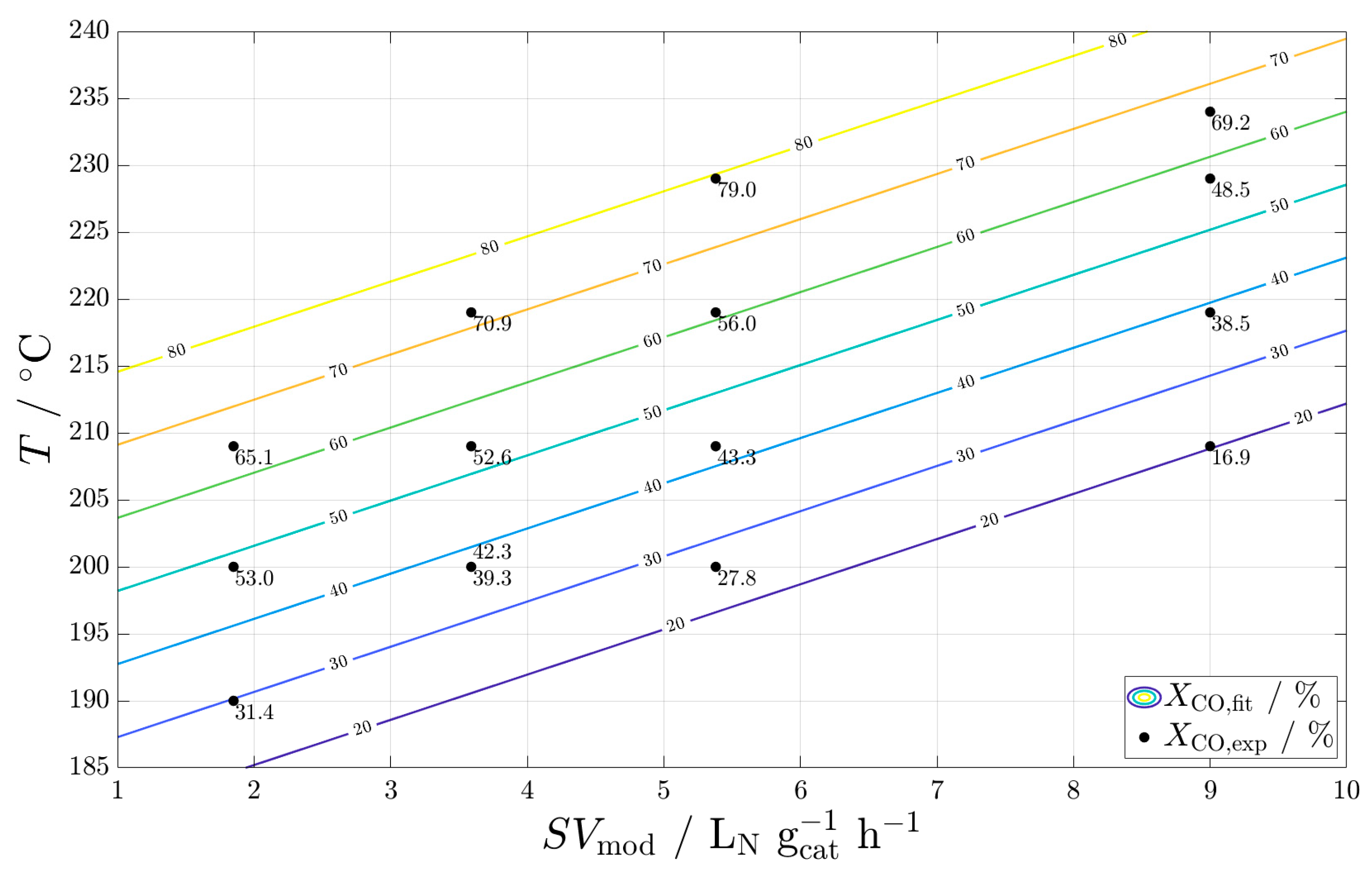
We fitted the CO conversion to a model equation in the form of Equation (10). The inputs were normalized to the axis limits shown in Figure 3 and the output was normalized to [10; 90]. The quality of the fit can be found in the Supplementary Information.
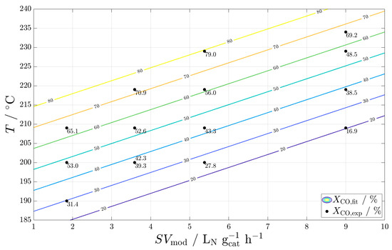
Figure 3.
Experimental and fitted results for CO conversion in the plane generated by modified space velocity and temperature.
From the fit, we deduce that the reactor design is capable of high conversion XCO = 70% from Ftotal = 30 LN h−1 (100% load) to Ftotal = 6 LN h−1 (20% load) to operate after change in renewable energy production. The load change is achieved by changing the temperature from about T = 238 to 210 °C. Regarding the dynamics of the reactor and its periphery, we observed the following: 1. the MFCs adjust each new flow rate within seconds, 2. the thermostat has a heating rate of about 0.5 K min−1, and 3. the thermostat has a cooling rate (passive cooling) of about 1 K min−1. This means that such a change happens within one online GC measurement (about 1 h) in our case, as can be seen in the Supplementary Information between setpoints 14 and 1R. Mass-spectrometry would be beneficial to evaluate the dynamics more in-depth.
This reactor with Vcat = 4.4 cm3 is mrct = 3.25 kg of which mrct,AM = 0.43 kg is additively manufactured. It can be scaled-up eight-fold to Vrct’ = 30.2 cm3 by increasing the length to lcat’ = 107 mm and the number of channels to eight; see Supplementary Information. Since the characteristic dimension dslit = 1 mm is constant, we assume that the temperature control is equally good. The weight of the AM part increases to mrct,AM’ = 1.2 kg and that of the entire part to mrct = 4.02 kg. The production time with an optimized scanning strategy is about two days on the same printer. The shape of the base plate is optimized to accommodate an even larger reactor on the same printer. Printers with much larger build space and higher build rates are available [37].
5. Conclusions and Outlook
We have demonstrated a reactor concept suitable for decentralized production of SAF. The laboratory-scale reactor was successfully operated under fluctuating, difficult input conditions for FTS. Temperature management was excellent. We observed high C5+ productivity and low methane selectivity. Temperatures measured inside the reactor confirmed quasi-isothermal behavior, and no catalyst deactivation occurred over the observed period. The reactor achieved leakage-free operation at pmax = 20 bar and Tmax = 400 °C with wall thicknesses of 1 mm or less.
This study demonstrated some of the many advantages of metal AM over conventional fabrication methods, such as a streamlined reactor design and fabrication that allows complex reactor geometries with fewer parts and seamless integration of sensors. The production time for the laboratory-scale reactor presented is about one day. Compared to other manufacturing methods, an AM reactor has a shorter lead time and lower cost. This is true for both lab-scale reactors and small-scale production reactors such as those needed for concepts, e.g., those in [38,39]. At higher reactor capacities and lot- sizes, other fabrication methods are likely to be advantageous due to economies of scale.
The current design is considered a baseline and will be further improved, e.g., to include taps. AM design freedom will be used to further improve heat and mass transfer. Fabrication time will be reduced, e.g., by reducing wall thickness. The reactor design will be revised with respect to temperature control during the reduction and removal of spent catalyst.
Subsequent work will seek certification of a larger AM reactor by a notified body. Scaling up and further streamlining of the production process will enable this type of reactor to be transferred to serial production.
Supplementary Materials
The following are available online at https://www.mdpi.com/article/10.3390/en16196798/s1, Figure S1: Process flow diagram of test rig; Figure S2: Reactor in test rig; Figure S3: CO conversion over time on stream; Figure S4: Quality of the fit. Figure S5: Experimental CO conversion; Figure S6: Computer-aided design image of reactor concept; Table S1: Materials; Table S2: Scan strategy: order and details of features; Table S3: Reactor in this work; Table S4: Shell Pearl GTL; Table S5: Sasol Oryx GTL; Table S6: Additional parameters required for criteria calculation; Table S7: Results of criteria indicate. References [40,41,42,43,44,45,46,47,48,49,50,51,52] are cited in the supplementary materials.
Author Contributions
Conceptualization, D.F.M., C.K. and R.D.; methodology, D.F.M.; software, D.F.M.; validation, D.F.M.; formal analysis, D.F.M.; investigation, D.F.M.; resources, C.K. and R.D.; data curation, D.F.M.; writing—original draft preparation, D.F.M.; writing—review and editing, D.F.M., C.K. and R.D.; visualization, D.F.M. and C.K.; supervision, C.K. and R.D.; project administration, C.K. and R.D.; funding acquisition, R.D. All authors have read and agreed to the published version of the manuscript.
Funding
We are grateful to the German Federal Ministry of Education and Research (BMBF) for funding the work through the project Kopernikus P2X-Phase 2 (Funding ID: 03SFK2K0-2).
Data Availability Statement
Data can be made available upon request.
Acknowledgments
We sincerely thank: the KIT-Publication Fund of the Karlsruhe Institute of Technology for its support, the funding bodies of the Large Scale Data Facility (https://www.scc.kit.edu/forschung/11843.php, accessed on 20 August 2023), Niko Heikkinen of VTT Technical Research Center of Finland for supplying the catalyst used in this study, and our colleagues Fabian Rupp, Manuel Hofheinz, Cornelia Schorle, Dennis Scherhaufer, Ketsanee Wai-Asa, Conrad Grehl, Dorela Dhamo.
Conflicts of Interest
The authors declare no conflict of interest.
Nomenclature
| Abbreviations | |
| AM | Additive manufacturing |
| BET | Brunauer Emmett Teller |
| Cn | Hydrocarbon with n carbon atoms |
| C5+ | Hydrocarbons with number of carbon atoms ≥ 5 |
| FID | Flame ionization detector |
| FTS | Fischer-Tropsch Synthesis |
| GC | Gas chromatograph |
| MFC | Mass flow controller |
| O | Olefin |
| P | Paraffin |
| PBF-LB/M | Powder bed fusion with laser beam of metals |
| PtL | Power to Liquid (liquid chemical energy carrier) |
| SAF | Sustainable Aviation Fuel |
| SLM | Selective laser melting, s. PBF-LB/M |
| STL | Standard Tessellation Language |
| TCD | Thermal conductivity detector |
| Latin Symbols | |
| A | Area (mm2) |
| a | Spacing (mm) |
| d | Diameter, depth (mm) |
| F | Volumetric flow rate (LN h−1) |
| H | Enthalpy (J) |
| l | Length (mm) |
| m | Mass (kg) |
| Molar flow (mol s−1) | |
| n | Number (-) |
| P | Productivity (g h−1) |
| p | Pressure (bar) |
| q | Standard helium leakage rate (mbar L s−1) |
| Heat flow (W) | |
| S | Selectivity (mol/mol) |
| STY | Space time yield (kg m−3 h−1) |
| SV | Space velocity at standard conditions (LN m−3 h−1) |
| t | Thickness, dimension (mm) |
| t | Time (s) |
| TOS | Time on stream (h) |
| V | Volume (mm3) |
| w | Width (mm) |
| X | Conversion (mol/mol) |
| y | Molar fraction (mol/mol) |
| Greek symbols | |
| Chain growth probability (-) | |
| Δ | Difference (diverse) |
| Angle (°) | |
| (h) | |
| Weight fraction (g/g) | |
| Subscripts | |
| c | Cooling |
| cat | Referring to catalyst or catalytic zone |
| e | Empty |
| f | Fin |
| hex | Heat transfer |
| mod | Modified, in this work: related to catalyst mass |
| N | Standard conditions (p = 1.01325 bara, T = 273.15 K) |
| p | Particle, pin |
| R, rct | Reaction |
| w | Wall |
References
- Fuel Cells and Hydrogen 2 Joint Undertaking. Hydrogen-Powered Aviation: A Fact-Based Study of Hydrogen Technology, Economics, and Climate Impact by 2050; Publications Office of the European Union: Luxembourg, 2020; Available online: https://data.europa.eu/doi/10.2843/471510 (accessed on 25 August 2023).
- Schripp, T.; Anderson, B.E.; Bauder, U.; Rauch, B.; Corbin, J.C.; Smallwood, G.J.; Lobo, P.; Crosbie, E.C.; Shook, M.A.; Miake-Lye, R.C.; et al. Aircraft engine particulate matter emissions from sustainable aviation fuels: Results from ground-based measurements during the NASA/DLR campaign ECLIF2/ND-MAX. Fuel 2022, 325, 124764. [Google Scholar] [CrossRef]
- Lee, D.S.; Fahey, D.W.; Skowron, A.; Allen, M.R.; Burkhardt, U.; Chen, Q.; Doherty, S.J.; Freeman, S.; Forster, P.M.; Fuglestvedt, J.; et al. The contribution of global aviation to anthropogenic climate forcing for 2000 to 2018. Atmos. Environ. 2021, 244, 117834. [Google Scholar] [CrossRef]
- Bullerdiek, N.; Neuling, U.; Kaltschmitt, M. A GHG reduction obligation for sustainable aviation fuels (SAF) in the EU and in Germany. J. Air Transp. Manag. 2021, 92, 102020. [Google Scholar] [CrossRef]
- Kern, J. Decarbonisation or defossilisation? Innovative alternative fuels for the aviation in Brazil: An international reference Model. In Proceedings of the Eleventh Meeting of the SBSTA Research Dialogue (RD 11) Science for Transformation (SBSTA 50), Bonn, Germany, 20 June 2019. [Google Scholar]
- Pfeifer, P.; Biffar, L.; Timm, F.; Böltken, T. Influence of Power-to-Fuel Plant Flexibility Towards Power and Plant Utilization and Intermediate Hydrogen Buffer Size. Chem. Ing. Tech. 2020, 92, 1976–1982. [Google Scholar] [CrossRef]
- Bieringer, T.; Bramsiepe, C.; Brand, S.; Brodhagen, A.; Dreiser, C.; Fleischer-Trebes, C.; Kockmann, N.; Lier, S.; Schmalz, D.; Schwede, C.; et al. White Paper Modular Plants. 2016. Available online: https://dechema.de/en/About+DECHEMA/Press/Reports+and+position+papers/ProcessNet+Positionspapiere/2016+7+White+Paper+Modular+Plants.html (accessed on 25 August 2023).
- Hsu, C.S.; Robinson, P.R. (Eds.) Springer Handbook of Petroleum Technology, 1st ed.; Springer: Cham, Switzerland, 2017; ISBN 9783319493459. [Google Scholar]
- Van de Loosdrecht, J.; Botes, F.G.; Ciobica, I.M.; Ferreira, A.; Gibson, P.; Moodley, D.J.; Saib, A.M.; Visagie, J.L.; Weststrate, C.J.; Niemantsverdriet, J.W. Fischer-Tropsch synthesis: Catalysts and chemistry. In Comprehensive Inorganic Chemistry II; Reedijk, J., Poeppelmeier, K., Eds.; Elsevier: Amsterdam, The Netherlands, 2013; pp. 525–557. ISBN 9780080965291. [Google Scholar]
- Bertoncini, F.; Marion, M.C.; Brodusch, N.; Esnault, S. Unravelling Molecular Composition of Products from Cobalt Catalysed Fischer-Tropsch Reaction by Comprehensive Gas Chromatography: Methodology and Application. Oil Gas Sci. Technol. Rev. IFP 2009, 64, 79–90. [Google Scholar] [CrossRef]
- Dry, M.E. High quality diesel via the Fischer-Tropsch process—A review. J. Chem. Technol. Biotechnol. 2002, 77, 43–50. [Google Scholar] [CrossRef]
- Almeida, L.C.; Echave, F.J.; Sanz, O.; Centeno, M.A.; Arzamendi, G.; Gandía, L.M.; Sousa-Aguiar, E.F.; Odriozola, J.A.; Montes, M. Fischer–Tropsch synthesis in microchannels. Chem. Eng. J. 2011, 167, 536–544. [Google Scholar] [CrossRef]
- Maitlis, P.M.; Klerk, A.D. Greener Fischer-Tropsch Processes for Fuels and Feedstocks, 1st ed.; Wiley-VCH: Weinheim, Germany, 2013; ISBN 9783527329458. [Google Scholar]
- Kolb, G. Review: Microstructured reactors for distributed and renewable production of fuels and electrical energy. Chem. Eng. Process. Process Intensif. 2013, 65, 1–44. [Google Scholar] [CrossRef]
- Brandner, J.J. Microfabrication in metals and polymers. In Micro Process Engineering: Fundamentals, Devices, Fabrication, and Applications; Kockmann, N., Ed.; Elektronische Ressource; Wiley-VCH: Weinheim, Germany, 2008; ISBN 3527312463. [Google Scholar]
- Cao, C.; Hu, J.; Li, S.; Wilcox, W.; Wang, Y. Intensified Fischer–Tropsch synthesis process with microchannel catalytic reactors. Catal. Today 2009, 140, 149–156. [Google Scholar] [CrossRef]
- Piermartini, P.; Böltken, T.; Selinsek, M.; Pfeifer, P. Influence of channel geometry on Fischer-Tropsch synthesis in microstructured reactors. Chem. Eng. J. 2017, 313, 328–335. [Google Scholar] [CrossRef]
- LeViness, S.; Tonkovich, A.L.Y.; Jarosch, K.; Fitzgerald, S.; Yang, B.; McDaniel, J. Improved Fischer-Tropsch Economics Enabled by Microchannel Technology. 2011. Available online: https://www.researchgate.net/publication/267236523_Improved_Fischer-Tropsch_Economics_Enabled_by_Microchannel_Technology (accessed on 25 August 2023).
- Selinsek, M. Compact Fischer-Tropsch Synthesis in Gas-to-Liquid Applications. In Proceedings of the 2nd Thematic Workshop, Prague, Czech Republic, 23–24 May 2019; Available online: https://www.comsynproject.eu/publications/ (accessed on 20 August 2023).
- Deshmukh, S.R.; Tonkovich, A.L.Y.; Jarosch, K.T.; Schrader, L.; Fitzgerald, S.P.; Kilanowski, D.R.; Lerou, J.J.; Mazanec, T.J. Scale-Up of Microchannel Reactors for Fischer-Tropsch Synthesis. Ind. Eng. Chem. Res. 2010, 49, 10883–10888. [Google Scholar] [CrossRef]
- Choudhury, H.A.; Cheng, X.; Afzal, S.; Prakash, A.V.; Tatarchuk, B.J.; Elbashir, N.O. Understanding the deactivation process of a microfibrous entrapped cobalt catalyst in supercritical fluid Fischer-Tropsch Synthesis. Catal. Today 2020, 343, 112–124. [Google Scholar] [CrossRef]
- Milewski, J.O. Additive Manufacturing of Metals: From Fundamental Technology to Rocket Nozzles, Medical Implants, and Custom Jewelry; Springer International Publishing: Cham, Switzerland, 2017; ISBN 9783319582047. [Google Scholar]
- Grinschek, F.; Ladewig, B.; Navarrete Munoz, A.; Klahn, C.; Dittmeyer, R. Getting Chemical and Biochemical Engineers Excited about Additive Manufacturing. Chem. Ing. Tech. 2022, 94, 931–938. [Google Scholar] [CrossRef]
- Xie, D. Additively Manufactured Permeable-Dense Composites and Its Applications in Microstructured Reactors. Doctoral Dissertation, Karlsruher Institut für Technologie, Karlsruhe, Germany, 2021. [Google Scholar]
- Stoll, P.; Spierings, A.; Wegener, K. Impact of a process interruption on tensile properties of SS 316L parts and hybrid parts produced with selective laser melting. Int. J. Adv. Manuf. Technol. 2019, 103, 367–376. [Google Scholar] [CrossRef]
- González-Castaño, M.; Baena-Moreno, F.M.; Navarro de Miguel, J.C.; Miah, K.U.M.; Arroyo-Torralvo, F.; Ossenbrink, R.; Odriozola, J.A.; Benzinger, W.; Hensel, A.; Wenka, A.; et al. 3D-printed structured catalysts for CO2 methanation reaction: Advancing of gyroid-based geometries. Energy Convers. Manag. 2022, 258, 115464. [Google Scholar] [CrossRef]
- Avril, A.; Hornung, C.H.; Urban, A.; Fraser, D.; Horne, M.; Veder, J.-P.; Tsanaktsidis, J.; Rodopoulos, T.; Henry, C.; Gunasegaram, D.R. Continuous flow hydrogenations using novel catalytic static mixers inside a tubular reactor. React. Chem. Eng. 2017, 2, 180–188. [Google Scholar] [CrossRef]
- Fratalocchi, L.; Groppi, G.; Visconti, C.G.; Lietti, L.; Tronconi, E. Adoption of 3D printed highly conductive periodic open cellular structures as an effective solution to enhance the heat transfer performances of compact Fischer-Tropsch fixed-bed reactors. Chem. Eng. J. 2020, 386, 123988. [Google Scholar] [CrossRef]
- Hauser, A.; Weitzer, M.; Gunsch, S.; Neubert, M.; Karl, J. Dynamic hydrogen-intensified methanation of synthetic by-product gases from steelworks. Fuel Process. Technol. 2021, 217, 106701. [Google Scholar] [CrossRef]
- Wei, Q.; Li, H.; Liu, G.; He, Y.; Wang, Y.; Tan, Y.E.; Wang, D.; Peng, X.; Yang, G.; Tsubaki, N. Metal 3D printing technology for functional integration of catalytic system. Nat. Commun. 2020, 11, 4098. [Google Scholar] [CrossRef]
- Grinschek, F.; Charles, A.; Elkaseer, A.; Klahn, C.; Scholz, S.G.; Dittmeyer, R. Gas-tight means zero defects—Design considerations for thin-walled fluidic devices with overhangs by laser powder bed fusion. Mater. Des. 2022, 223, 111174. [Google Scholar] [CrossRef]
- Gibson, I.; Rosen, D.; Stucker, B.; Khorasani, M. Additive Manufacturing Technologies; Springer International Publishing: Cham, Switzerland, 2021. [Google Scholar]
- Klahn, C. Laseradditiv Gefertigte, Luftdurchlässige Mesostrukturen: Herstellung und Eigenschaften für die Anwendung; Springer: Berlin/Heidelberg, Germany, 2015; ISBN 9783662477601. [Google Scholar]
- Myrstad, R.; Eri, S.; Pfeifer, P.; Rytter, E.; Holmen, A. Fischer-Tropsch synthesis in a microstructured reactor. Catal. Today 2009, 147, S301–S304. [Google Scholar] [CrossRef]
- Kirsch, H.; Lochmahr, N.; Staudt, C.; Pfeifer, P.; Dittmeyer, R. Production of CO2-neutral liquid fuels by integrating Fischer-Tropsch synthesis and hydrocracking in a single micro-structured reactor: Performance evaluation of different configurations by factorial design experiments. Chem. Eng. J. 2020, 393, 124553. [Google Scholar] [CrossRef]
- van der Laan, G.P.; Beenackers, A.A.C.M. Kinetics and Selectivity of the Fischer–Tropsch Synthesis: A Literature Review. Catal. Rev. 1999, 41, 255–318. [Google Scholar] [CrossRef]
- Griffiths, L. TCT Buyer’s Guide 2022; Rapid News Group: Chester, UK, 2022. [Google Scholar]
- Dittmeyer, R.; Klumpp, M.; Kant, P.; Ozin, G. Crowd oil not crude oil. Nat. Commun. 2019, 10, 1818. [Google Scholar] [CrossRef] [PubMed]
- Vidal-Vázquez, F.V.; Koponen, J.; Ruuskanen, V.; Bajamundi, C.; Kosonen, A.; Simell, P.; Ahola, J.; Frilund, C.; Elfving, J.; Reinikainen, M.; et al. Power-to-X technology using renewable electricity and carbon dioxide from ambient air: SOLETAIR proof-of-concept and improved process concept. J. CO2 Util. 2018, 28, 235–246. [Google Scholar] [CrossRef]
- DIN EN ISO 4022:2018-12; Durchlässige Sintermetallwerkstoffe: Bestimmung der Flüssigkeitsdurchlässigkeit. Beuth Verlag GmbH: Berlin, Germany, 2018. Available online: https://www.nautos.de/OJG/search (accessed on 20 August 2023).
- Kirsch, H. Dezentrale Synthese Strombasierter Flüssiger Kraftstoffe über die Fischer-Tropsch Route. Ph.D. Thesis, Karlsruher Institut für Technologie, Karlsruhe, Germany, 2020. [Google Scholar] [CrossRef]
- Flory, P.J. Molecular Size Distribution in Linear Condensation Polymers. J. Am. Chem. Soc. 1936, 58, 1877–1885. [Google Scholar] [CrossRef]
- Kaiser, R.E. Gas-Chromatographie. 2. Aufl. Bd. 22. B I Hochschultaschenbücher; Bibliographisches Institut: Mannheim, Germany, 1973; ISBN 3411000228. [Google Scholar]
- Brübach, L.T. Katalytische Hydrierende Spaltung von Fischer-Tropsch Produkten im Technikumsmaßstab. Master’s Thesis, Karlsruher Institut für Technologie, Karlsruhe, Germany, 2018. [Google Scholar]
- Pabst, K.; González, M.I.; Kraushaar-Czarnetzki, B.; Schaub, G. Combination of Fischer–Tropsch Synthesis and Hydroprocessing in a Single-Stage Reactor. Part I. Mathematical Modeling of the Reaction Kinetics. Ind. Eng. Chem. Res. 2013, 52, 8978–8987. [Google Scholar] [CrossRef]
- Shell. Pearl GTL Overview. Available online: https://www.shell.com/about-us/major-projects/pearl-gtl/pearl-gtl-an-overview.html (accessed on 3 July 2023).
- MAN Energy Solutions. Shell Pearl GTL—Gas-to-Liquid Reactor in Qatar for Shell. Available online: https://www.man-es.com/process-industry/products/chemical-reactors/water--air--oil-operated-reactors (accessed on 3 July 2023).
- Hydrocarbons Technology. Oryx. Available online: https://www.hydrocarbons-technology.com/projects/oryx/ (accessed on 3 July 2023).
- 2011. Available online: https://docplayer.net/45263490-Our-projects-oryx-gtl.html (accessed on 25 August 2023).
- Berger, R. EUROKIN Spreadsheet on Requirements for Measurement of Intrinsic Kinetics in the Gas-Solid Fixed-Bed Reactor. 2010. Available online: https://eurokin.org/wp-content/uploads/downloads/2019/08/EUROKIN_fixed-bed_html_guide.pdf (accessed on 15 September 2023).
- Jess, A.; Wasserscheid, P. Chemical Technology: An Integral Textbook; Wiley-VCH: Weinheim, Germany, 2013; ISBN 978-3-527-30446-2. [Google Scholar]
- Pfeifer, P. Application of catalysts to metal microreactor systems. In Chemical Kinetics; Patel, V., Ed.; InTech Europe: Rijeka, Croatia, 2012; pp. 325–345. ISBN 978-953-51-0132-1. [Google Scholar]
Disclaimer/Publisher’s Note: The statements, opinions and data contained in all publications are solely those of the individual author(s) and contributor(s) and not of MDPI and/or the editor(s). MDPI and/or the editor(s) disclaim responsibility for any injury to people or property resulting from any ideas, methods, instructions or products referred to in the content. |
© 2023 by the authors. Licensee MDPI, Basel, Switzerland. This article is an open access article distributed under the terms and conditions of the Creative Commons Attribution (CC BY) license (https://creativecommons.org/licenses/by/4.0/).