1. Introduction
Today, Organic Rankine Cycle (ORC) technology is the unrivaled technical solution to the production of electricity (or the coproduction of electricity and heat) from a wide-ranging variety of energy sources [
1]. However, the actual contribution of ORCs to the world’s electricity-generating capacity is minimal. The total installed capacity of ORC plants is approximately 2.7 GW [
2], i.e., 0.042% of the global electricity-generating capacity and 0.068% of the generating capacity based on thermal energy sources [
3]. Such a marginal contribution from ORCs is caused mainly by economic reasons. ORC systems are too expensive, especially in the case of low-grade heat sources (<100 °C) and low power ranges [
4,
5,
6].
Isobaric expansion (IE) technology presents a promising solution for recovering and utilizing low-grade heat in mini- and medium-scale applications [
7]. The IE process offers an alternative to conventional processes commonly observed in contemporary heat engines, which involves a pressure decrease throughout the cycle. The basic principle of the IE engine is to generate useful power at a constant high cycle pressure and perform the cycle compression stage at a constant low cycle pressure. As a result, the engine’s design becomes simplified, and the contribution of thermal and mechanical losses to the overall cycle efficiency can be significantly reduced compared to conventional heat engines.
IE engines are the oldest types of heat engines. It will suffice to mention that Savery, Newcomen, and Watt pumps fit this group [
8,
9]. These machines were later replaced by more efficient, well-known water steam expansion machines such as piston steam engines and turbines. Over the past few decades, many IE engines have been proposed and studied again under different names and for different applications [
10,
11,
12,
13,
14,
15,
16,
17]. The current status of IE technology and essential modifications to make IE machines competitive and cost-effective alternatives to state-of-the-art heat conversion technologies are presented in [
7]. These systems are almost noiseless, can be fully balanced, and have a simple, reliable, and inexpensive design. Some versions of the IE engines proposed in [
7] avoid typical technical problems associated with well-known thermal-energy-driven systems, such as failure of sealing components, lubrication, and wear.
IE engines directly convert heat into mechanical energy in a convenient hydraulic or pneumatic form, which can be readily converted into various other forms of energy. Among the notable applications, IE engines show great promise as vapor-driven pumps and compressors due to their straightforward design. In such applications, heat can be efficiently utilized for direct pumping and compression without the intermediate steps of generating shaft power or electricity, subsequent transmission, and reconversion to mechanical energy, as commonly practiced in current industrial processes. These methods hold significant potential for replacing primary fossil energy sources with readily available low-grade heat, even at temperatures below 100 °C.
Encouraging experimental and theoretical results have been obtained with IE engine pumps driven by low-grade heat sources [
16,
17,
18,
19,
20,
21,
22]. The engine can also work as a compressor. Steam/vapor-driven compressors are similar to direct-acting steam pumps, although the processes differ. They were used to actuate the air brakes of steam locomotives [
23,
24]. Multiple patents exist on steam/vapor-driven compressors [
25,
26,
27,
28,
29,
30]. However, according to our knowledge, studies of such engines as compressors are almost entirely missing in the literature, and, to date, no application has been found for this compression technology.
A new vapor-driven reciprocating compressor based on IE engines has recently been presented, and a preliminary assessment of its feasibility has been carried out [
31]. There are many potential applications for the presented technology. IE compressors can replace conventional electrically driven compressors in all cases in which a low-grade heat source of sufficient capacity is available. The compression of air for energy storage systems and hydrogen, as well as air conditioning and vapor compression refrigeration, are examples of promising applications. Solar energy and waste heat from truck and ship diesel engines are ideal heat sources for vapor-driven compressors. In the future, such a source may be the waste heat of various fuel cells and computer data centers. All types of electrically driven compressors used today in refineries and chemical and food processing plants can, in many cases, also be replaced by compressors driven by multiple sources of waste heat, which are typical for such industries.
The findings in reference [
31] indicated that the driving vapor is utilized inefficiently in the simplest compressor configurations. This inefficiency arises because a significant portion of the driving vapor’s energy is consumed by compressing the vapor itself. Consequently, energy transfer efficiency from the driving vapor to the compressed fluid is lower than in IE engine pumps. Based on this analysis, multistage compression is anticipated to provide advantages for vapor-driven compressors.
This paper aims to present multistage vapor-driven reciprocating compressors based on IE engines and conducts a comprehensive analytical thermodynamic analysis of these compressors. The analysis considers single-stage and multistage compression processes, with and without intercooling of the compressed gas between stages. These topics represent the novelty of the present work.
The results demonstrate that, for vapor-driven compression, the benefits of multistage compression are superior to those known for conventional compression processes. Multistage vapor-driven compression not only reduces compression work and temperature rise but, more significantly, diminishes the adverse compression effects on the driving vapor within the driver, thereby substantially enhancing vapor utilization efficiency. Additionally, the total volume of the heat engine experiences a substantial reduction as the number of stages increases. Consequently, under specific process conditions, the overall dimensions of the compressors and engines may also decrease with an increasing number of stages.
2. Process Schemes and Assumptions
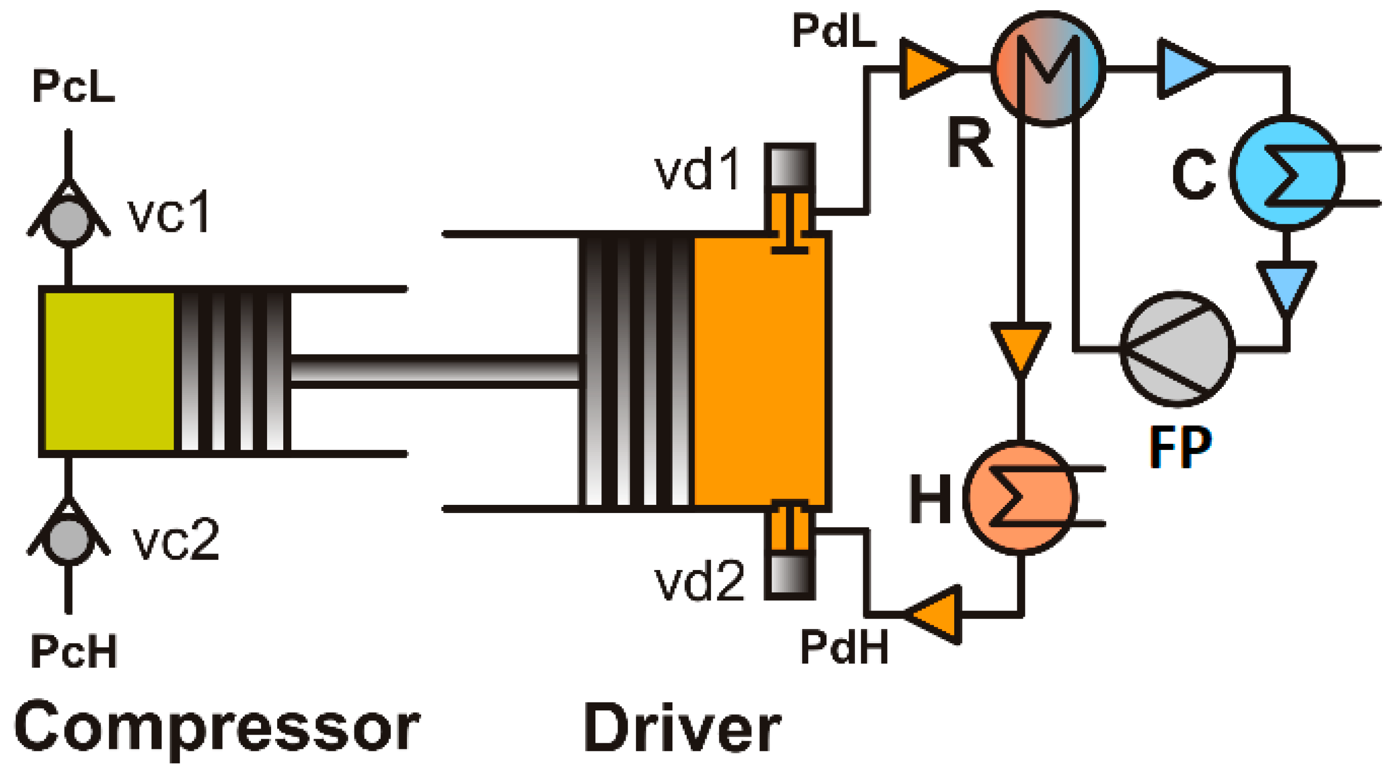
Figure 1 illustrates the fundamental configuration of a single-acting reciprocating vapor-driven compressor. It comprises a compressor and driver cylinders equipped with pistons connected by a connecting rod. The driver cylinder is integrated with a vapor generation circuit (depicted in the single-acting scheme), which includes a heater (H), recuperator (R), cooler (C), and feed pump (FP). The driver cylinder, in conjunction with the vapor circuit, constitutes an isobaric expansion (IE) heat engine, the operational principles of which are detailed in reference [
7]. The heat engine replaces the conventional piston reciprocating compressors’ electric motor or internal combustion engine and the crank mechanism.
The processes occurring within the compressor and driver are described in reference [
10]. The compressor’s operation can be orchestrated by appropriately selecting the dimensions of the compressor and driver pistons and the high and low pressures of the driving vapor. For a double-acting compressor and driver (not depicted in
Figure 1), compression and actuation occur on both sides of the pistons, rendering the forward and backward strokes identical. Therefore, arbitrary low and high driver pressures (
and
) can be utilized for a given set of low and high compressor pressures (
and
). If friction is neglected, the relationship between the pressures and areas of the piston ensuring uniform piston movement (excluding top and bottom dead centers) can be expressed as [
31]:
In the case of the single-acting configuration (
Figure 1), the forces acting on the pistons impose limitations on the range of driver pressures for given compressor pressures. These limitations can be circumvented by employing modified, more flexible single-acting schemes (with an additional receiver or duplex design) elucidated in reference [
31]. For the modified single-acting schemes, Equation (1) remains valid.
In the subsequent analysis, considering the modified single-acting schemes, there is no need to differentiate between single-acting and double-acting configurations. Any desired pressure in the compressor can be accommodated by employing arbitrary low and high pressures in the driver.
When multiple compressor cylinders are arranged in series and gas or vapor is compressed in stages, the setup is called a multistage or stage compressor. Stage compression finds wide application in scenarios where high compression ratios are required. In nearly all multistage applications, the compressed gas or vapor is cooled between stages, as intercooling allows for a compression process that more closely approximates isothermal compression, resulting in reduced power consumption.
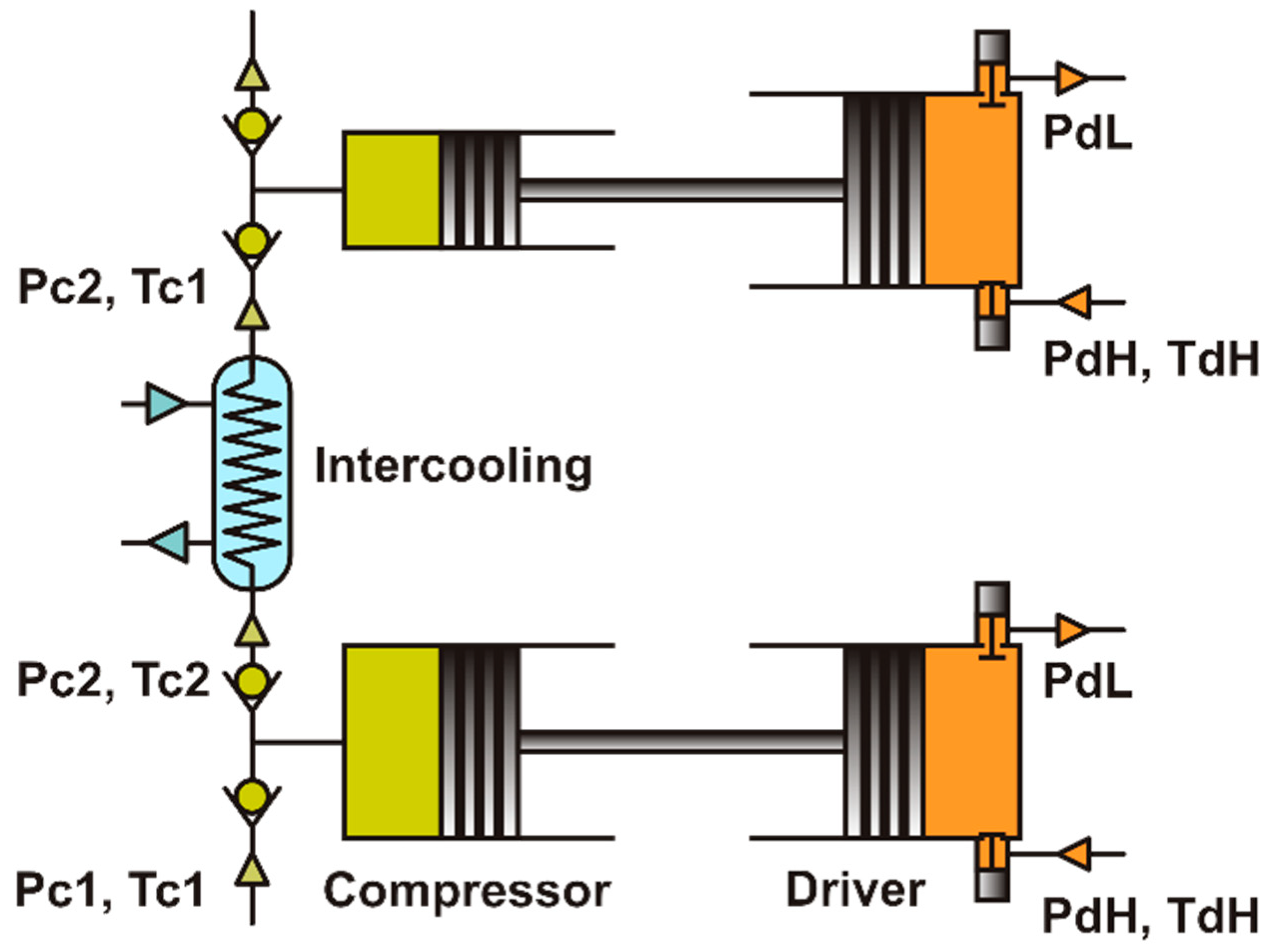
Figure 2 depicts the simplest configuration of two-stage vapor-driven compression with intercooling. The modifications necessary for aligning arbitrary pressures in the compressors and drivers are not depicted for clarity. The same vapor source in this arrangement actuates each driver’s piston.
Our aim is to quantify the impact of stage compression in terms of energy efficiency and the dimensions of the compressors and drivers. We assume that the intake valves of the drivers remain open throughout the compression and discharge stages of the compressors, ensuring that the pressure in the drivers corresponds to the variable pressure in the compressors. Moreover, we assume that the pistons move without acceleration, except for the top and bottom dead points. To achieve such driver operation technically, the characteristic time for pressure increase in the driver should be shorter than the characteristic time for force equalization in the compressor and driver.
The analysis we present here is based on several standard assumptions for simplicity. These assumptions are as follows:
The processes occurring in the compressor and driver are assumed to be adiabatic and reversible.
The driver only performs useful work on the compression process.
The minimum volumes of the compression and driving cylinders are negligible, indicating no clearance.
The temperature and pressure of the fluids in the driver and compressor are assumed to be uniform.
Mechanical friction between moving and stationary parts in contact, such as the piston and cylinder or the piston rod and stuffing box, is considered to be negligible.
The inertia of the pistons, piston rods, and fluids is assumed to be negligible.
The cross-sectional area of the piston rods is much smaller compared to the area of the pistons.
The compressed and driving fluids are treated as ideal gases with constant heat capacities.
Intercooling is assumed to be perfect, meaning that the compressed gas is cooled to the temperature of the intake gas.
The pressure ratio is the same in all stages, which is the condition for achieving minimum work for compression with perfect intercooling [
32].
It is essential to highlight that the primary objective of multistage vapor-driven compression is to enhance the efficiency of vapor utilization rather than solely focusing on minimizing temperature rise and reducing compression work. Therefore, in the scope of this study, we also consider processes without intercooling.
3. Efficiency of Driving Gas Utilization
The energy efficiency of the whole compression system is determined by the efficiencies of the compressors and drivers and by the efficiency of the heat engine. In this paper, as in the previous one [
31], we will focus on the efficiency of the drivers for different numbers of compression stages.
In the case of
-stage compression with the total pressure ratio
and the same pressure ratio in all stages, the pressure ratio in each compressor stage is
Therefore, the initial pressure at stage
is:
Since the piston strokes of the compressor and the driver are the same at each stage, the ratio of the volumes of the driver and the compressor at each stage (strictly speaking, the volumes covered by the pistons) is equal to the ratio of the areas of the pistons, Equation (1), which can be represented as:
From this equation, the ratio of the volumes and piston areas increases with the stage number proportional to or , see Equation (2).
The total volume of the drivers can be obtained from Equation (3).
Using the ideal gas state equation
the consumed mass of the driving gas in each stage can be expressed as:
where
is the specific volume of the driving gas supplied to the driver and
is the dimensionless temperature of the driving gas at the end of the compression stroke at stage
. The equation for the temperature of the driving gas at the end of the compression stroke was derived in [
31] (Equations (14) and (21) in [
31]).
where
is the cycle compression work at stage
:
Substituting the expressions for
and
from Equations (3) and (8), into Equation (7) we get:
in which
is the dimensionless compression cycle work at stage
.
Since
does not depend on the stage number,
, the dimensionless temperature
in Equation (9) is the same for each stage. Therefore, the total mass of the driving gas consumed per cycle may be represented as:
The energy efficiency of the driver process can be characterized by the ratio of the total cycle work
to the consumed mass of the driving gas,
, i.e., as the specific work [
31].
The specific work can be obtained from Equations (4), (11) and (13) in the form:
In the limit of a large number of stages (
the numerator and denominator in Equation (14) tend to:
In this case,
approaches 1 as can be seen from Equations (9), (10) and (15), i.e., the driver process becomes close to isothermal, and the specific work approaches its limiting value.
From the physical point of view, the isothermal driver process results from the fact that at a large number of stages, pressure changes in the compressor and driver approach zero as the compressor pressure ratio approaches 1 and no thermal effects occur.
It is worth noting that the limiting efficiency, Equation (16), is also achieved for an arbitrary number of stages when the compressor operates as an ideal pump at each stage. This can easily be proved: the driver performs the maximum possible work, , whereas the mass of the consumed driving gas is .
An important conclusion can be drawn from Equation (14): the specific work does not depend on the intercooling of the compressed gas between stages. This is because the work for compressing an ideal gas is independent of the pressure level for a given compression ratio.
The efficiency of driving gas use can be defined as the relative specific work.
The efficiency increases with the number of stages and in the limit of large its value approaches 1. In this case, pressure changes in the compressor and driver at each stage are negligible, and the process is the same as in an ideal pump.
Figure 3 shows examples of the efficiency of the driving gas used for one-, two-, and three-stage compression as a function of the compressor and driver pressure ratios. Significant improvement in efficiency is observed when the number of stages increases, mainly if two-stage compression is used instead of single-stage compression.
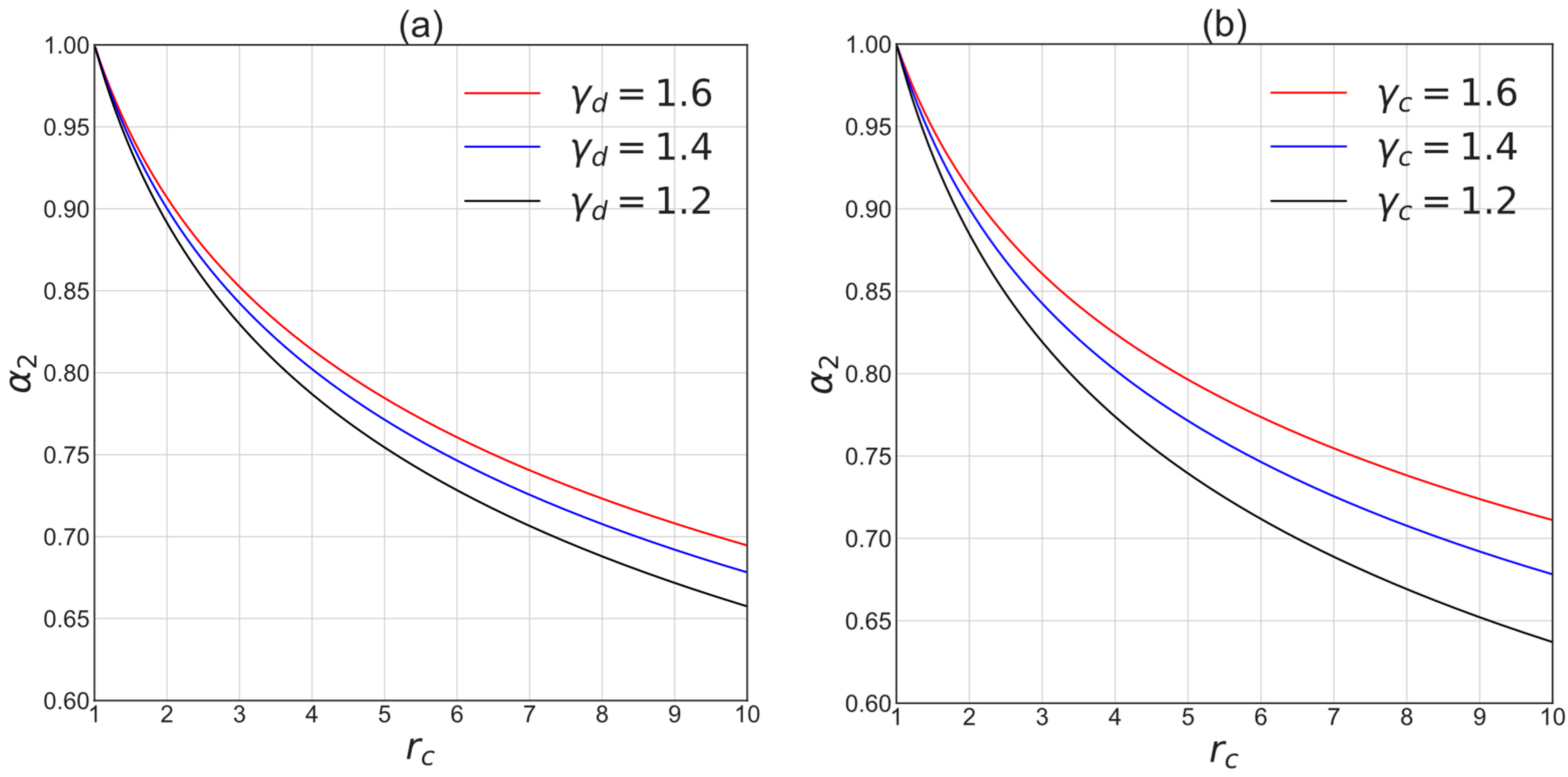
The influence of the properties of the compressed and driving gases on the efficiency of the two-stage compression is shown in
Figure 4. The higher the heat capacity ratios of the compressed and driving gas, the more efficient the driving gas use is.
From Equation (17) and
Figure 3 and
Figure 4, the pressure ratio in compressor
has a major effect on the efficiency of the driving vapor use.
The energy efficiency of the vapor-driven multistage compression process can also be characterized in terms of the consumption of the driving gas
relative to its amount in the single-stage compression,
.
where
are the mass of the driving gas consumed per cycle, the volume of the driver, and dimensionless temperature of the driving gas at the end of compression stroke in the case of single-stage compression
.
Using Equations (12) and (17), the relative amount of the consumed driving gas in the
-stage compression can be expressed as:
In the stage compression without intercooling, the total compression work
does not depend on the number of stages (
) and
can be calculated as:
If the compressed gas is cooled between the stages to the temperature of the intake gas, we can write:
and the total cycle work, Equation (13), in this case is:
In the limiting case of a large number of stages (, it approaches the work of isothermal compression .
The compression work of the single-stage compression is:
Hence,
and the relative amount of the consumed driving gas in the stage compression with intercooling can be expressed as:
Consumption of the driving gas in multistage compression processes decreases significantly compared to single-stage compression, especially at high compressor pressure ratios. This is illustrated in
Figure 5, which shows the relative amounts of the driving gas from Equations (23) and (28).
The results presented in
Figure 5 are not sensitive to the ratio of heat capacities of the gases. Therefore, only the results for
= 1.4 are presented.
Qualitatively, the influence of multistaging on the consumption of the driving gas for compression with intercooling is similar to that without intercooling. However, with intercooling, the effect is stronger by a factor of
, Equation (27) and
Figure 5. The
value is the ratio of the multistage compression work to the work of single-stage compression, which characterizes the well-known saving in work in stage compression with intercooling.
Figure 6 illustrates this effect.
In the next section, we will compare the sizes of single-stage and multistage vapor-driven compression systems with and without intercooling, assuming that the volume of the compressor in the first stage is the same.
4. Dimensions of the Compressors and Drivers
If the compressed gas is cooled between the stages to the temperature of the intake gas, the interstage pressures and volumes are related by Equation (24). If the gas is compressed adiabatically in each stage and there is no intercooling between the stages, then
Instead of Equations (24) and (29), we will use one equation.
in which
for processes with intercooling, and
for processes without intercooling.
From Equations (3) and (30), volume of the compressor at stage
can be expressed as:
From Equation (31) with different
values (1 and
) one can find that compressor volume at stage
in compression with intercooling is
times less than that without intercooling. The total volume of the compressors in
-stage compression is:
It increases with the number of stages; in the limit of a large number of stages proportionally to as
Using Equations (2), (3) and (31) the volume of the driver at stage
can be obtained.
where
is the volume of the driver in the case of single-stage compression, Equation (20).
From Equation (33), it follows that in the compression process with intercooling (
the driver volume at stage
is independent of the stage number
. The total volume of the drivers in
-stage compression
can be obtained using this equation. Without intercooling it may be represented as follows:
In the limit of a large number of stages ( the total volume of the drivers approaches the limiting values:
The relative total volumes of the compressors
and drivers
for two- and three-stage compression processes and their limiting values for a large number of stages depending on the compressor compression ratio are shown in
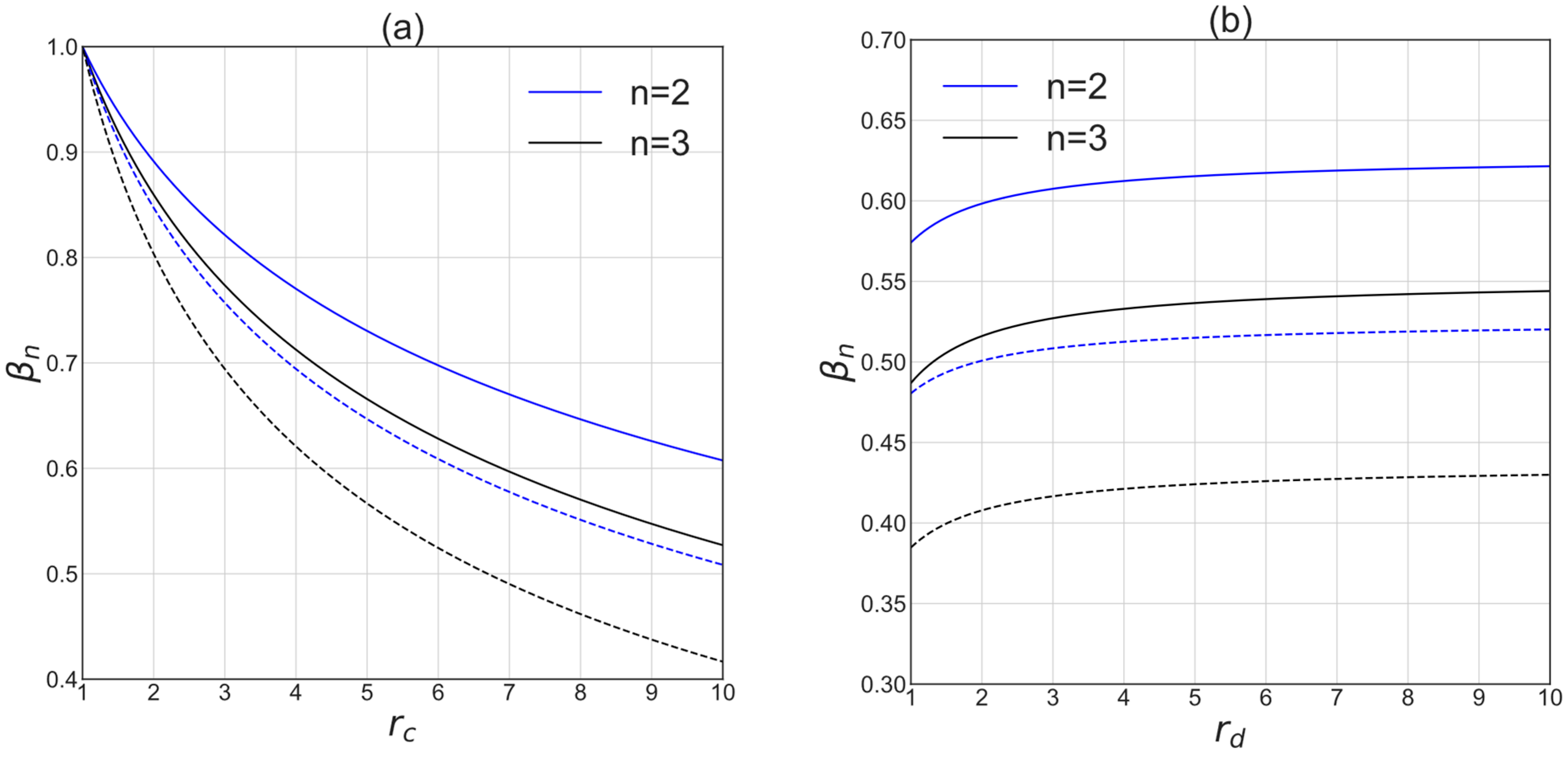
Figure 7.
Both in the compression processes with and without intercooling, the total volume of the drivers in stage compression decreases with the number of stages and the pressure ratio
as seen in
Figure 7b. As shown in
Figure 7b, a significant decrease in the total driver volume is observed when two- or three-stage compression is used instead of single-stage compression.
From Equations (33)–(36) it follows that multistaging permits a substantial decrease in the total volume of the drivers. For example, for compression without intercooling at a compressor pressure ratio of 10 and the total volume of the drivers can be decreased by 2.8 times at a large number of stages. For a process with intercooling and the same compressor pressure ratio it can be decreased by a factor of 3.9. At a large compressor pressure ratio , the total volumes of the drivers in the case of a large number of stages, Equations (36) and (37), approach theoretically zero.
Depending on the pressures in the compressor and driver, their total volume
can increase and decrease with the number of stages. An example of the ratios of the total volumes of the two-stage and single-stage vapor-driven compression units without intercooling (compressors and drivers)
depending on the compressor and driver pressure ratios are shown in
Figure 8.
The reduction in the total volume of the compressor-drive unit with the number of stages occurs when the volume of the drive of the single-stage unit is greater than the volume of the compressor.
The results presented in
Figure 7 and
Figure 8 show that the advantages of multistage compression over single-stage compression in terms of system sizes can be significant.
5. Discussion and Conclusions
This paper presents a thermodynamic analysis that extends the study of vapor utilization efficiency in vapor-driven compressors to include multistage compression processes. The analysis is simplified by making several assumptions, most typical in thermodynamic research. However, one exception is the assumption that the driving vapor behaves as an ideal gas with constant heat capacity. Although this assumption is not valid when considering engine processes with phase changes in the working fluid, it allows for obtaining analytical solutions that yield qualitative insights into the impact of changes in major operating parameters on actual performance. Additionally, previous research [
10] indicates that assuming an ideal gas is acceptable for assessing thermal efficiency.
The main finding of this analysis is that multistage vapor-driven compressors can effectively mitigate the drawbacks of single-stage vapor-driven compressors and serve as a valuable alternative to conventional compressors, particularly multistage ones powered by electric motors. The advantages of multistage compression over single-stage compression are more pronounced in vapor-driven compression than in conventional compression processes. Multistaging of vapor-driven compression not only reduces compression work and prevents significant temperature increases but also alleviates adverse compression effects on the driving gas/vapor in the driver.
Consequently, multistage compression can substantially enhance vapor utilization efficiency, with the most significant impact observed when employing two-stage compression instead of single-stage compression. Similar to single-stage compression, the compressor pressure ratio significantly influences the efficiency of driving vapor utilization. Moreover, the total volume of the drivers decreases significantly with an increasing number of stages.
In most conventional multistage compression processes, the compressed gas or vapor is cooled between stages to mitigate temperature rise, decrease compression work, and reduce the size of compressors in subsequent stages. In vapor-driven multistage compression processes, intercooling offers additional significant advantages. It leads to smaller volumes of drivers and reduces the amount of driving gas consumed. However, even without intercooling, vapor-driven multistage compression is a powerful method for enhancing process efficiency.
It is important to note that intercooling does not affect the vapor use efficiency if the vapor behaves as an ideal gas. This is because the dimensionless compression work remains the same for processes with and without intercooling. However, if the driving vapor is a real gas, the efficiency of processes with and without intercooling differs. Nevertheless, based on previous findings, the quantitative difference is expected to be insignificant.
One additional advantage of multistage compression is the reduction in the total volume of the compressors/engines. Although the total volume of the compressors may increase, the overall volume of the compression system can decrease due to a substantial decrease in the total volume of the compressors’ drivers. This size reduction is beneficial not only for compactness but also for cost savings on high-pressure equipment.
The main conclusion of the paper is that multistage vapor-driven compressors based on IE engines can be as efficient as IE engine pumps. This result opens up significant opportunities for energy savings in various compression processes. Compressing gases such as hydrogen, air, and ethylene to high pressure, requiring large amounts of energy, is an example of a promising application. Energy savings are achieved by replacing electricity with readily available low-grade heat sources (<100 °C).
Multistaging is just one of numerous potential approaches for enhancing simple vapor-driven compressors. Future publications will explore other effective strategies for advanced vapor-driven compressors.
