Article

Research on Cavitation Performance of Bidirectional Integrated Pump Gate

1
Huanan Pump Co., Ltd., Guangzhou 511400, China
2
Huanan Pump (Ganzhou) Co., Ltd., Ganzhou 342200, China
3
National Research Center of Pumps, Jiangsu University, Zhenjiang 212013, China
*
Author to whom correspondence should be addressed.
Energies 2023, 16(19), 6784; https://doi.org/10.3390/en16196784
Submission received: 22 July 2023 / Revised: 15 September 2023 / Accepted: 18 September 2023 / Published: 23 September 2023
(This article belongs to the Special Issue Complex Flow in Fluid Machinery)

Abstract

:
A pump gate is a device that controls the flow of water. It can stop the flood when it comes, drain the ponding gathered in the city, and improve the water circulation of the city. Traditional pumping stations require a large land area, and their pump houses and gates need to be designed separately. Furthermore, the construction period of traditional pumping stations is lengthy, and the maintenance costs are high. It can no longer meet the needs of modern cities for water environment management. Therefore, it is imperative to design a new type of pump gate. The integrated pump gate introduced in this paper is an integrated construction of gates and pumps to achieve automatic control and bidirectional operation. The research mainly consists of three parts: design of pumping station, theoretical analysis, and numerical calculation. By studying the unstable flow inside the integrated pump, the characteristics and the degree of cavitation occurrence are predicted. This can provide a reference basis for the optimal design and stability operation of the integrated pump gate. To investigate cavitation in an integrated pump gate, numerical simulations were performed for multiple operating conditions using the SST turbulence model. Constant numerical simulations of cavitation through numerical calculation, the characteristic curves of the integrated pump gate under forward and reverse operation at different flow points were obtained, and flow field analysis was performed for the model pump at 1.0 Q. The location and degree of cavitation occurrence were predicted. In this study, a preliminary analysis was conducted to investigate the influence of cavitation on the internal flow characteristics of integrated gate pumps. The research collected data related to cavitation characteristics, streamline patterns, and blade pressures. Additionally, the study explored the characteristics of cavitation phenomena, laying the foundation for the optimization of the design of bidirectional operation in integrated sluice gate pumps for future practical engineering applications.

1. Introduction

With the acceleration of the urbanization process and the frequent occurrence of extreme weather events, the water level in urban inland rivers and low-lying areas have been rising due to continuous precipitation. The traditional pump arrangements used are no longer sufficient to handle the flood control and drainage functions of cities. Therefore, there has been a demand to develop new and efficient pumping stations that meet the higher requirements of these functions. This is especially crucial as the traditional pump gate arrangements significantly reduce the flow exchange capacity of river courses and their ability to carry out flood control and drainage.
The inner and outer rivers are usually divided based on their location and function. Generally, the inner rivers are responsible for handling surface runoff and distributing main channel rivers within urban water bodies and channels. They are also a primary water source for irrigation and daily living. Meanwhile, the outer rivers mainly provide avenues for drainage. In the process of water exchange and replenishment in the inner river, when the water level falls below a certain predetermined level, the system will perceive that the inner river needs replenishment and trigger the pump gate closing procedure. The gate will suddenly and immediately close and the pump will automatically start, allowing the outer river water to be pumped into the inner river, thereby replenishing its water supply. Similarly, when the water level in the inner river hits a certain upper limit, the pumps automatically stop and the gates will open immediately. The excess water in the inner river will be discharged into the outer river by its own gravity. Water exchange and recharge in the inner river improves the water circulation in the town. These systems reduce siltation and black odor level in the inner river, which ultimately enhances the urban environment.
Generally speaking, when the water level in the inner lake, inner river, and nullah is depleted, the water level in the outer river will be slightly lower than the water level in the inner river, and the integrated gate’s gate will be open, allowing the pump to remain idle. However, in situations where the water level in the outer river is higher than that of the inner river, the integrated pump gate’s gate will be closed to prevent excessive water from entering the inner river. During heavy rainfall, when the water level in the inner river rises sharply, significantly higher than the water level in the outer river, the pump gate will open automatically to facilitate inner lake, inner river, and nullah drainage.
Conventional pump gates commonly utilize a divided structure, which entails intricate installation and occupies a substantial area. In contrast, the integrated pump gate presents a unified design, occupying minimal space and delivering noteworthy advantages in terms of economics, installation, maintenance, investment, construction duration, operational administration, and intelligent functionalities.
The pump in the integrated pump gate is directly installed on the gate, negating the need for an additional pump house or self-flow structure. It substantially increases the connecting cross section of the internal and outer river. However, the integrated pump gate may generate different flow patterns and hydraulic characteristics depending on the geometric models and different pump selection conditions. Flow turbulence may result in significant impact on the hydraulic characteristics and cavitation performance of the integrated pump gate, even cause damage to the unit. Therefore, it is necessary to conduct a comprehensive study on the hydraulic characteristics and cavitation of the integrated pump gate. Figure 1 and Figure 2 illustrate the integrated pump gate used in this paper.
Zhao Qing et al. [1] analyzed the advantages and disadvantages of the integrated pump gate and explained its scope of application. Tan Y [2] compared the advantages and disadvantages of different types of pump gates. Song Jian [3], in response to the issue of insufficient hydraulic power in the rivers of Fuzhou City, pioneered the introduction of an integrated pump gate system for river transformation. Combining the practical experience of the Luzhuang River project, he shared insights on the construction procedures and key points. The results demonstrated the significant promotional value of the integrated pump gate system and provided valuable experience for practical engineering applications. Ming Guo [4] studied the flow characteristics of the gate pump and the pump station inlet basin. He studied the liquid flow and air entrainment in the horizontal gate pump using the CFD method and established two three-dimensional flow fields for the bent pipe and horizontal gate pump. The effect of using the bent gate pump on reducing entrainment was discussed. The hydraulic model of the gate pump was improved. Hailong Li [5] studied common low-head riverbed type pump gates. He introduced the pre-design of pumps, the selection of pumps, and some basic principles in the design of this type of pumping station. This addressed some of the common problems in pumping stations. It has some reference value for other pump selection, design, and installation. Li Mingyu [6] pointed out the limited flood control and drainage capacity of the traditional pump gates designed for early establishment and the urgent need to design new pumping stations with larger water capacity to solve this problem. She also introduced in detail the design and technical points between different parts of the integrated pump gate, which provides a certain reference for the design and application of the integrated pump gate. Wu Liyan [7], based on actual engineering cases, established a mathematical model for risk assessment in water conservancy project construction, including sluices and pumping stations. Evaluation indicators for construction risks were proposed for projects involving sluices and pumping stations. Wei Zhenjuan [8] conducted research and analysis on the specific layout and installation parameters of pump gate projects. This study provided valuable references for the planning and construction of other pump gate projects. Fukumori Kentaro [9] developed a horizontal axial submersible pump, Verified that this pump standby operations can keep the peak water level low and maximize the water storage capacity of the drainage channel. Sun Xun [10] introduced the advantages in process extension of biological production by the emerging hydrodynamic cavity (HC) technology.
Cavitation research is a cornerstone of pump hydraulics research. That has been widely studied to address practical engineering problems. Researchers typically focus on NPSH and cavitation priming issues, pump cavitation damage, abnormal vibration, and noise control; head or power drop rates and continuous cavitation generation are key benchmarks in different areas. Recently, vibration noise has also been utilized on some occasions to judge cavitation priming.
Brennen et al. [11] conducted an in-depth study of the cavitation problem in high-speed turbine pumps in the 1970s. They proposed parameters such as cavitation flexibility and mass flow gain factor to characterize the cavitation dynamic characteristics. The global flow and pressure dynamic characteristics of cavitation flow in the pump caused by inlet flow and pressure perturbations were theoretically analyzed. They also focused on the scale effect and thermal effect of cavitation. These results became the classical content to describe pump cavitation.
Cavitation stability is also a significant concern among researchers. The rotational cavitation phenomenon, like rotational stall, was first identified in aerospace turbo pumps. Since then, a series of cavitation instability phenomena such as cavitation wheeze, alternating impeller cavitation, and asymmetric impeller cavitation have been discovered one after another. Researchers generally believe that flow instabilities such as rotational cavitation are mainly caused by the interaction between cavitation and adjacent blades developed within the blade grid flow path and the existence of characteristic frequencies associated with the axial frequency. Yang Fan et al. [12], focusing on the need for high flow rate and low head in urban flood control and drainage, conducted numerical calculations of bidirectional submersible mixed-flow pumps using computational fluid dynamics (CFD). Through model experiments, the hydraulic performance of the pump device was compared. The results indicated satisfactory flow patterns within the guide vanes during pump reversal, validating the effectiveness of numerical simulation. Design parameters for reference in the submersible mixed-flow pump were also provided.
Liu Jianfeng et al. [13], using a rainwater drainage pumping station as the research subject, conducted model experiments to study the energy characteristics, cavitation characteristics, and flyout characteristics of its fully mixed-flow pumps. Adjustments were made to the clearance errors of the mixed-flow pumps, ensuring the safe operation of the unit and further enhancing the performance of the pump device. Wu Wence [14] elaborated on the interaction between cavitation and vortex structure of water jet propulsion pumps by reducing inlet pressure.Long Yun and his team have conducted extensive research on the mechanism of cavitation phenomena and the morphology of vortex structures, revealing the process of cavitation evolution and the reasons for the development of vortex structures [15,16,17,18].
Xie, Chuanliu [19,20], and their colleagues improved the design of the combined pump gate’s inlet and outlet bell mouths through orthogonal optimization and optimized their design.In their numerical study, Wang, Z.Y. [21] employed a multiscale approach to investigate the internal structure of a distorted hydrofoil and the formation mechanism of cavitation. They proposed a microbubble generation model to elucidate the origin of numerous bubbles within the cavitation cavity. Wang Yongkang [22] conducted numerical calculations on the cavitation flow of inducers in turbopumps with different fluid media and proposed methods for improving the performance of turbopumps with different fluid media. This innovative approach enhanced the inlet conditions of the integrated pump gate and mitigated vortex flow in the outlet channel. As a result, the efficiency and safety of the integrated pump gate were significantly elevated. Zhang Guangjian [23,24] and his team have extensively conducted theoretical research on cavitation structures and two-phase flow within cavities. They have utilized X-ray imaging techniques to explore the two-phase flow inside the cavities. Ge, M et al. [25,26,27,28] conducted a categorization and study of cavitation induced by thermodynamic effects using methods such as dynamic mode decomposition. They also successfully suppressed cavitation in a Venturi reactor and enhanced cavitation performance.
In conclusion, while extensive research has been conducted on the hydraulic characteristics of conventional pump gates, there is a lack of research on the hydraulic characteristics and cavitation performance of integrated pump gates. Consequently, it is crucial to design integrated pump gates and study their hydraulic performance based on specific design specifications. This is necessary to ensure efficient and stable operation, and it will have a significant impact on the advancement of integrated pump gate technology.

2. Physical Model and Numerical Calculation Method

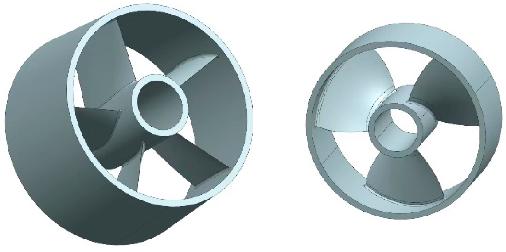
2.1. Geometric Models
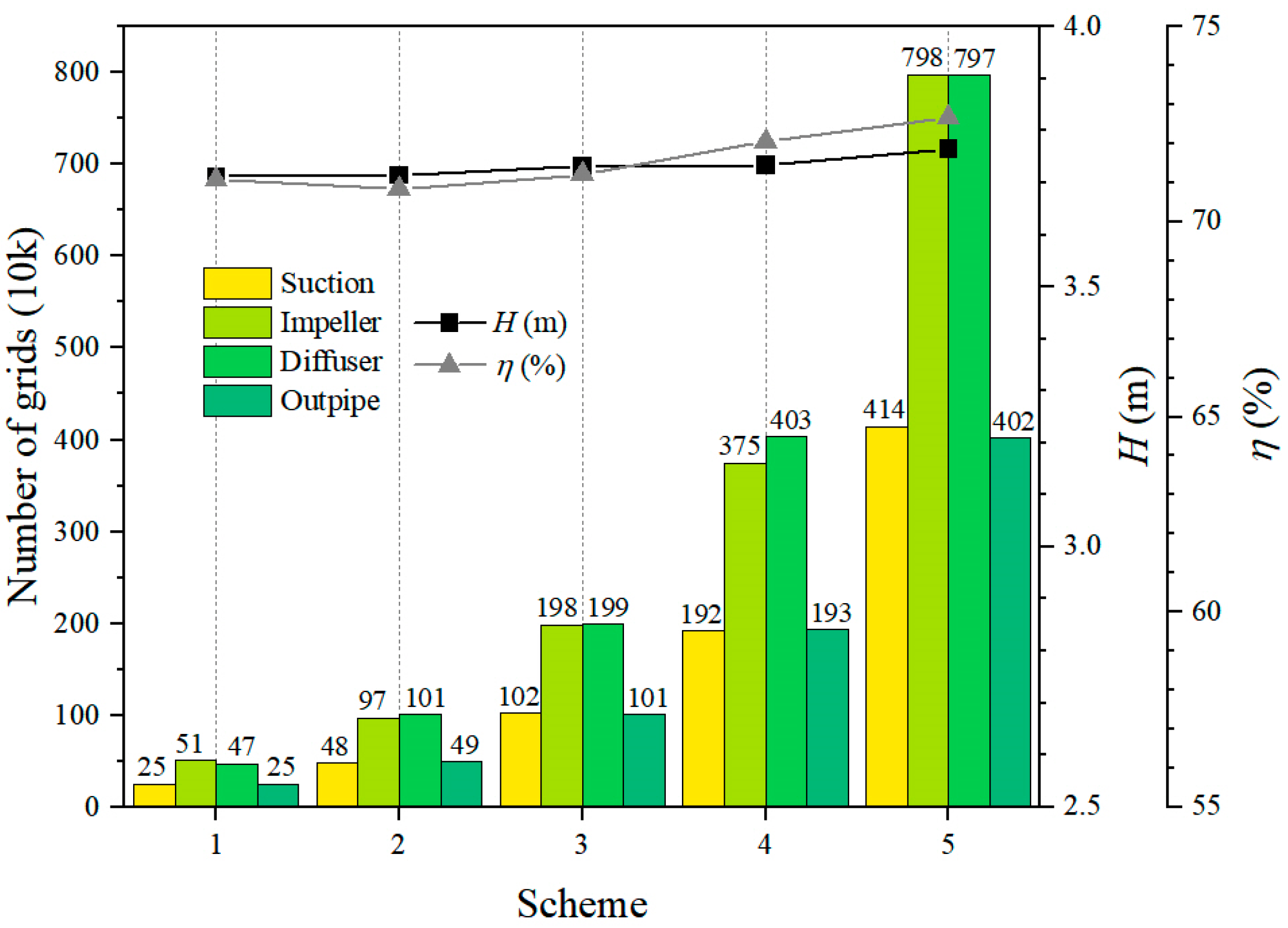
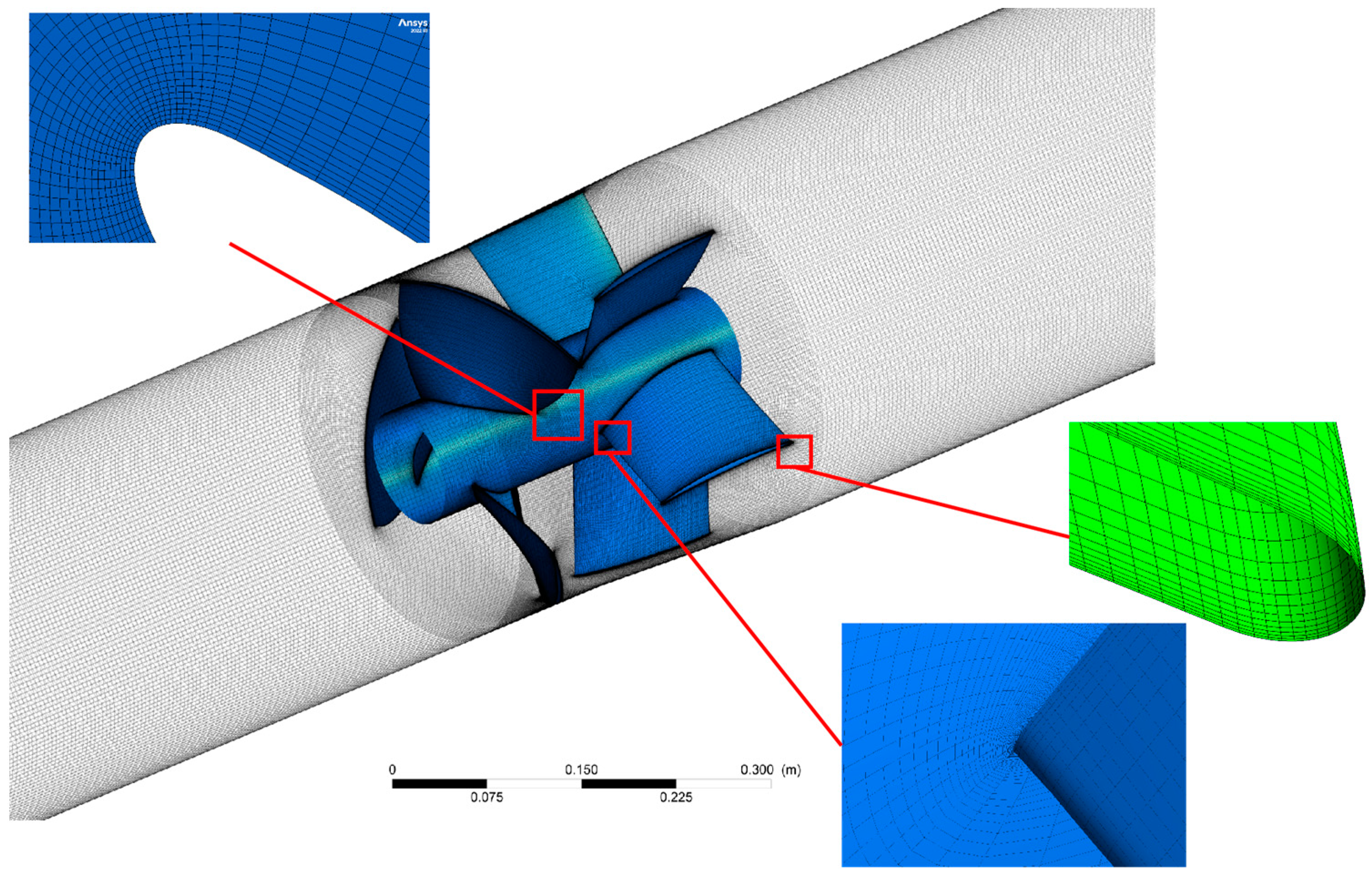
The selected bidirectional integrated pump has a rotation operating at a rated speed of 1450 r/min. In the forward rotation, the flow rate is Q = 315 kg/s, while in the reverse direction, the flow rate is Q = 252 kg/s. Its prominent structural parameters comprise a three-bladed impeller, five-bladed diffuser, an impeller diameter of 145 mm, and an impeller outlet diameter of d = 145 mm. The hydraulic model of the pump is shown in Figure 1. It encompasses the transformed overflow section in a three-dimensional configuration. The fluid domain is categorized into four distinct sections: the inlet pipe, impeller, diffuser, and outlet pipe.

2.2. Grid Division

To maximize the advantages of structured meshes, Turbo Grid and ICEM partitioned the inlet pipe, impeller, guide vane, and outlet pipe of the 3D model pump into hexahedral structural meshes. In order to eliminate the influence of the number of mesh quantity on accuracy, a grid-independence analysis was performed, as seen in Figure 3. The upper curve represents the content of the grid independence analysis, while the lower section displays a bar chart illustrating the mesh quantities. After analysis, the final grid quantity was 11,482,868. The specific information is shown in Table 1. The mesh diagram of the impeller and guide vane are depicted in Figure 4.

2.3. Numerical Calculation Method

2.3.1. Turbulence Model

SST k-ω model is widely applied in the field, as it incorporates the cross-diffusion of the ω equation and considers shear stress transport within turbulence, thereby mitigating excessive predictions of eddy viscosity. In practical applications, the SST k-ω model has exhibited notably higher precision than other models when numerically simulating low specific-speed axial flow pumps. Hence, this study employs the SST k-ω model for numerical computation of the integrated pump. Its mathematical expression is provided below:
ρ k u i x i = x j μ + μ t σ k 3 k x j + P k β * ρ k ω
ρ ω u i x i = x j μ + μ t σ ω 3 ω x j + α 3 ω k P k β 3 ρ ω 2 + 2 1 F 1 ρ 1 ω σ ω 2 k x j ω x j

2.3.2. Boundary Conditions

Boundary conditions are essential pre-processing settings in numerical simulations; they encompass the setting of rotational domain and stationary domain settings. The impeller domain is considered the rotating domain, while the inlet, outlet sections, and guide vane domain are treated as the stationary domain. In this study, the static and dynamic boundary surface type employed is Frozen Rotor, while the inlet and outlet conditions are set as total pressure inlet and mass flow outlet, respectively. Steady-state flow calculations are conducted to address cavitation in the pump model.

3. Analysis of Results

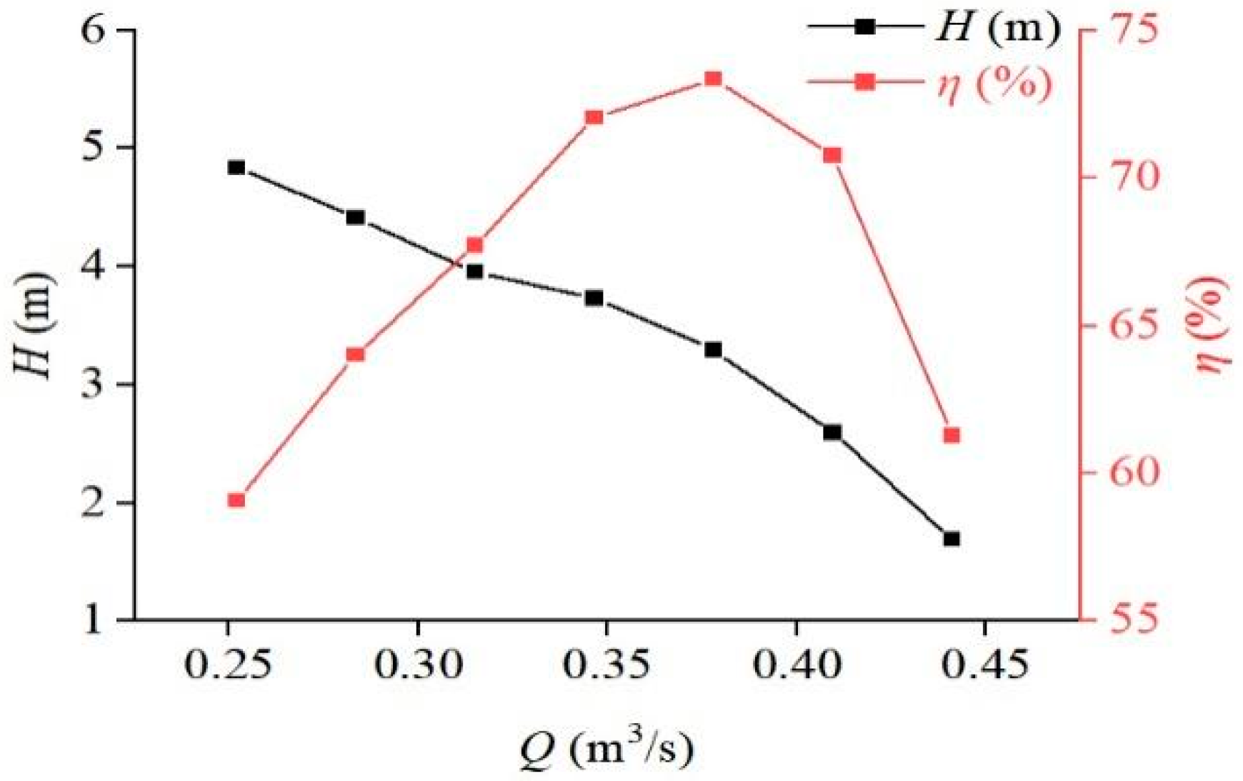
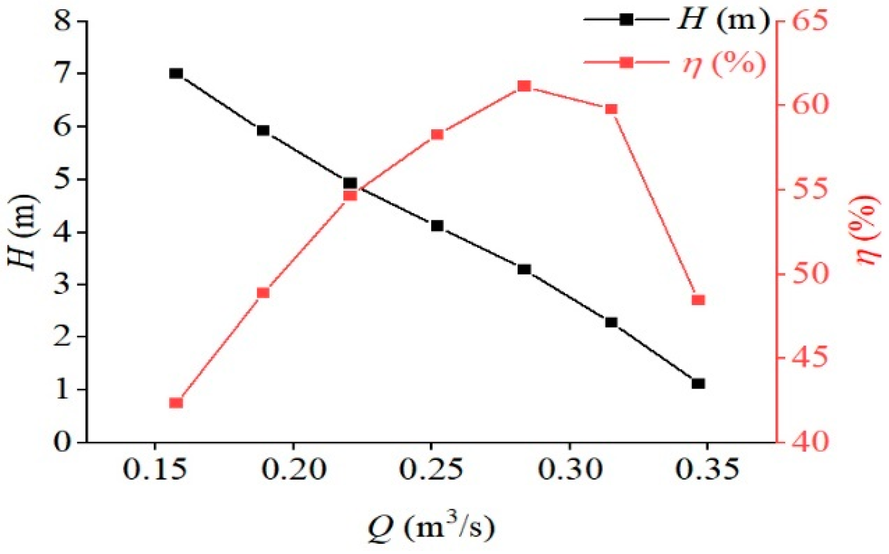
3.1. Bidirectional Operation Hydraulic Performance Curve of One-Piece Pump and Gate

In Figure 5 and Figure 6, the hydraulic performance curve of the integrated pumping station in both directions of operation are presented. The results indicate that the overall efficiency is slightly higher during forward operation compared to reverse operation, particularly at low flow rates. The head is slightly lower during forward operation compared to reverse operation. Additionally, both forward and reverse operations exhibit a trend of increasing efficiency initially with increasing flow rate, followed by a decrease. The head decreases with increasing flow rate as well.

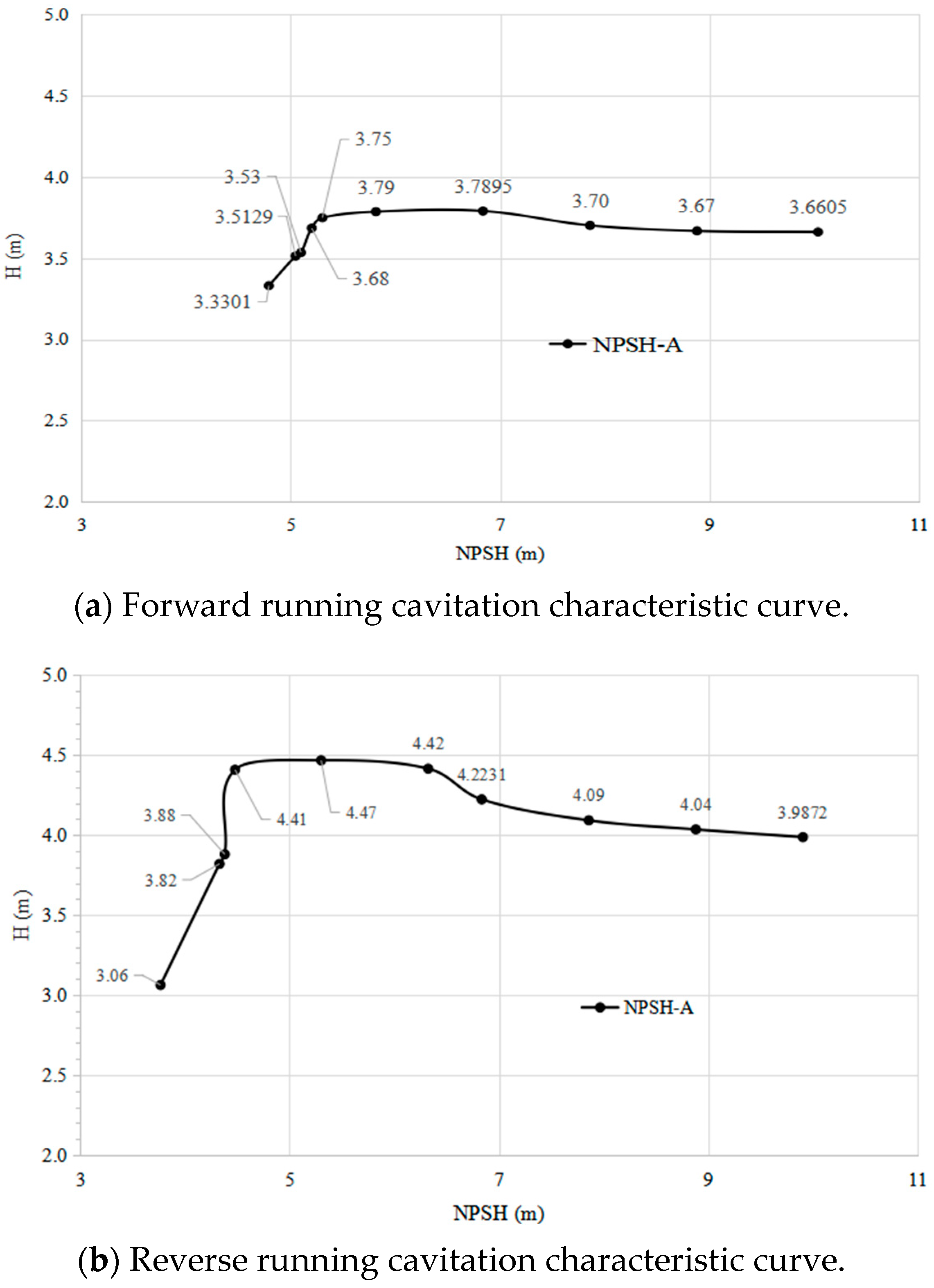
3.2. Cavitation Flow Analysis

The manifestation of cavitation and its subsequent collapse can considerably impact the steady functioning of a system, specifically within an integrated pump station. The presence of cavitation and whirlpool formations can significantly diminish the hydraulic efficiency of the entire system. This segment endeavors to scrutinize the characteristics of cavitation within the flow passage of a unified pump gate. The examination of cavitation employs the Zwart-Gerber-Belamri model as its fundamental basis. By changing the inlet pressure, the cavitation margin is calculated under the same operating conditions. The cavitation margin is determined according to the national standard GB/T 3216-2016 [29] for different flow rates. In the cavitation calculation section, the ambient temperature is set to 25 °C, which corresponds to a water density of 997.05 kg/m3. The meteorological density is 0.0185 kg/m3, and the corresponding saturation vapor pressure is 3.196 kPa.

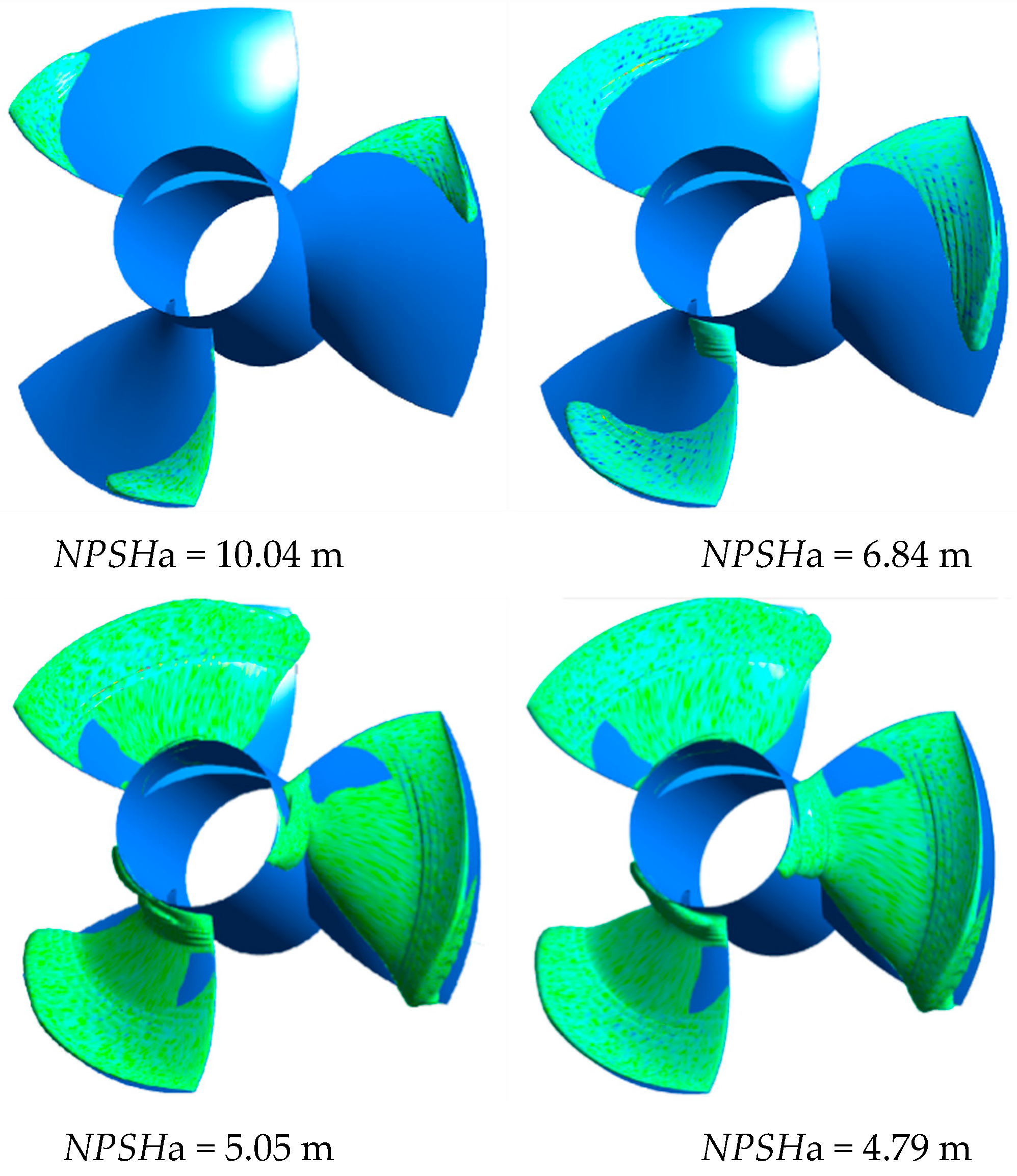
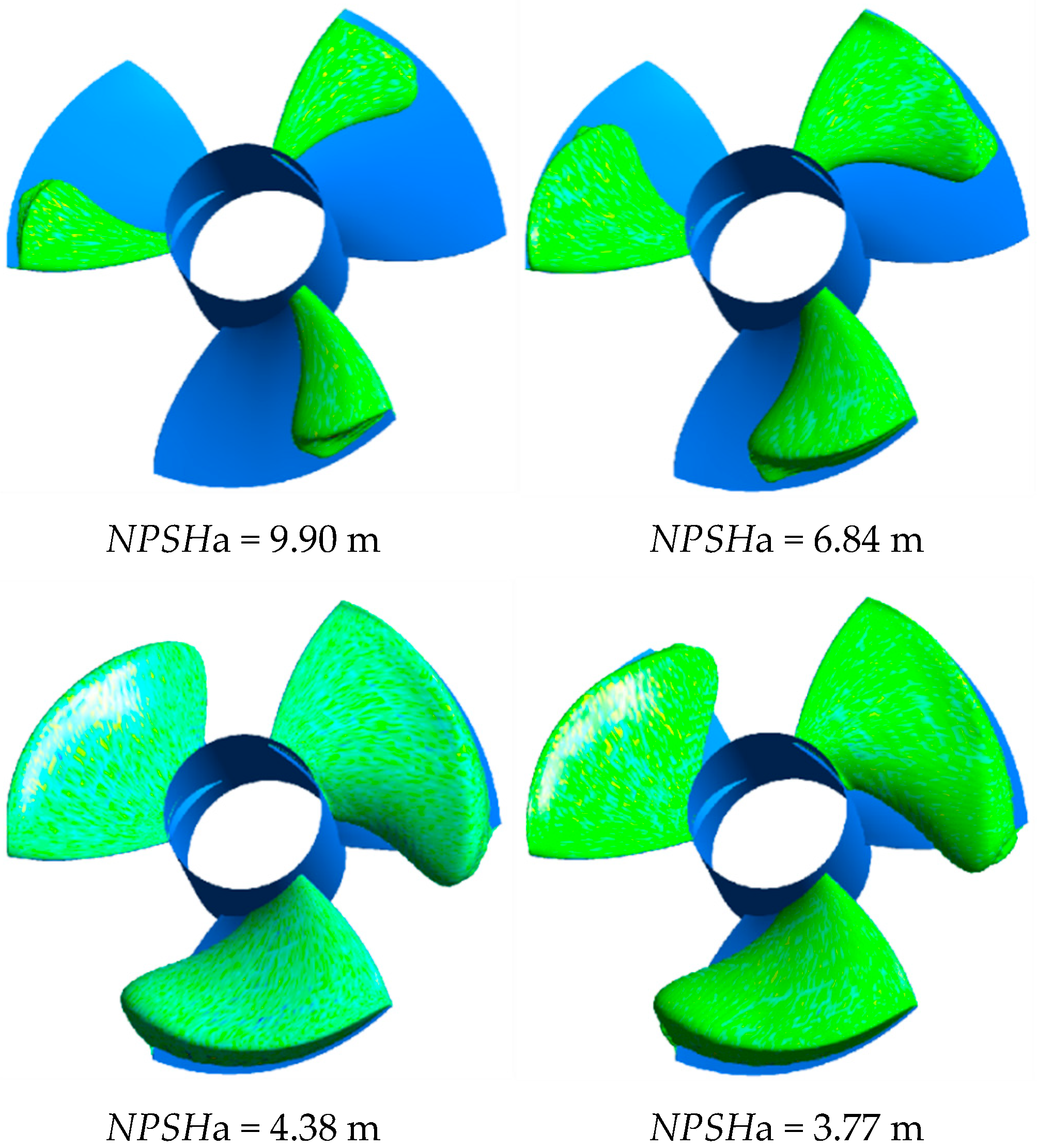
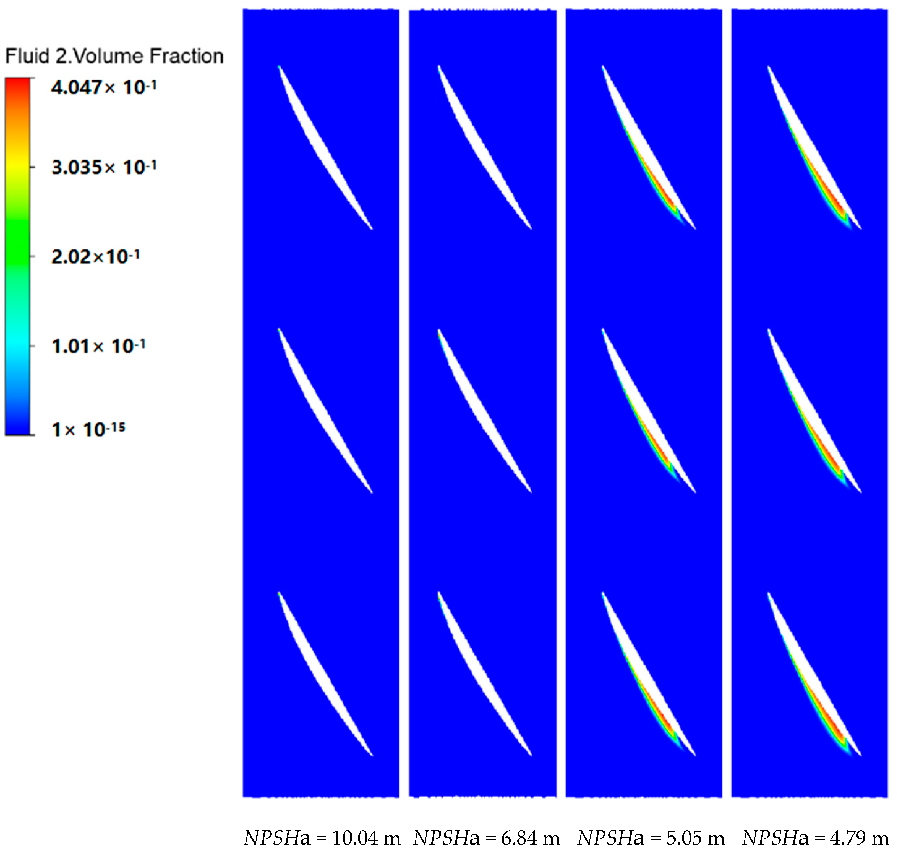
3.2.1. Impeller Cavitation Analysis

Cavitation is a phenomenon occurring in multiphase flows, where the fluid pressure, under specific temperature conditions, drops below the saturation vapor pressure and forms bubbles containing water vapor or other gases. The process involves various mechanical, chemical, electrochemical, and thermodynamic effects, releasing a substantial amount of energy. In this paper, the effective cavitation margin NPSHa is altered by reducing the inlet pressure. When the NPSHa diminishes such that the ratio of the drop in pump head to its original value reaches 3%, NPSHa at this point becomes the critical cavitation head. The formula for calculating it is provided below:
N P S H = P 1 ρ g + V 1 2 2 g P v ρ g
In the above equation, P1 is the average surface pressure at the upstream pressure measurement section, Pa; V1 is the average surface flow velocity at the upstream pressure measurement section, m/s; and Pv is the vaporization pressure, 3169 Pa.
The cavitation characteristics curve of the all-in-one pumping station in both directions is depicted in Figure 7. As illustrated, during the forward operation, NPSHa is higher than 5.05 m, and the forward operating head of the all-in-one pump station is stable at H = 3.67 m. As the inlet pressure decreases, i.e., when the effective cavitation margin decreases, the head of the centrifugal pump starts to gradually decrease. When NPSHa = 5.05 m, the head drops 3% and reaches the critical cavitation. The model pump’s NPSHa = 5.05 m in forward operation. Additinally, the head of the model pump is basically stable at H = 3.99 and NPSHa = 4.38 m in reverse operation when the NPSHa is greater than 4.38 m. When the effective cavitation margin falls below the critical cavitation margin, the head notably and suddenly decreases.

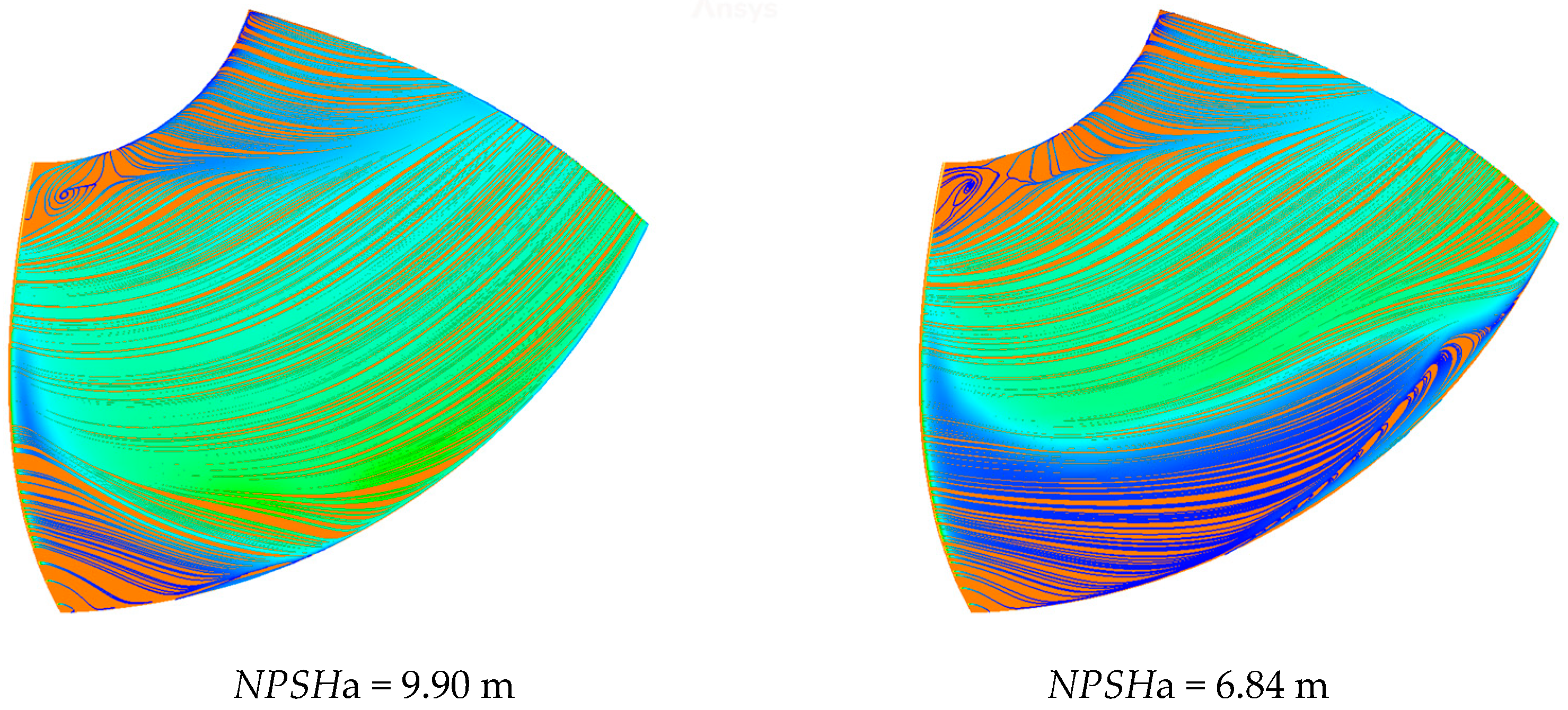
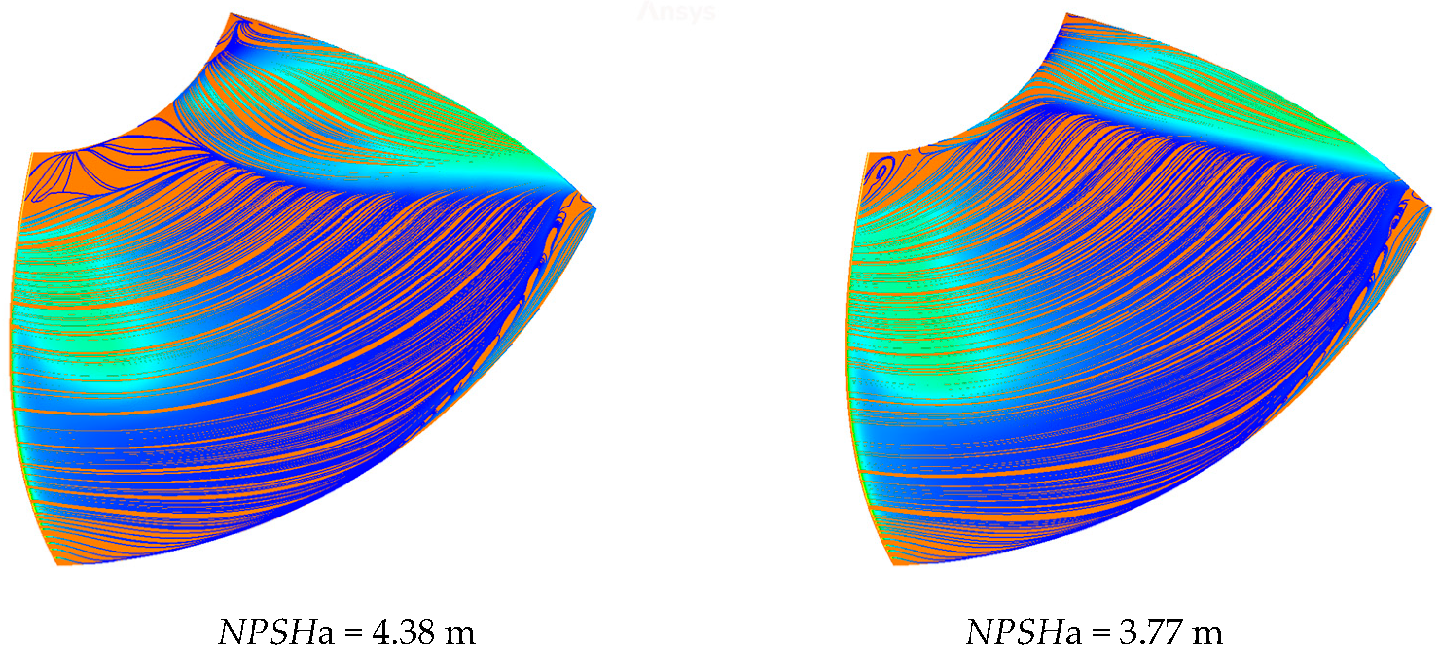
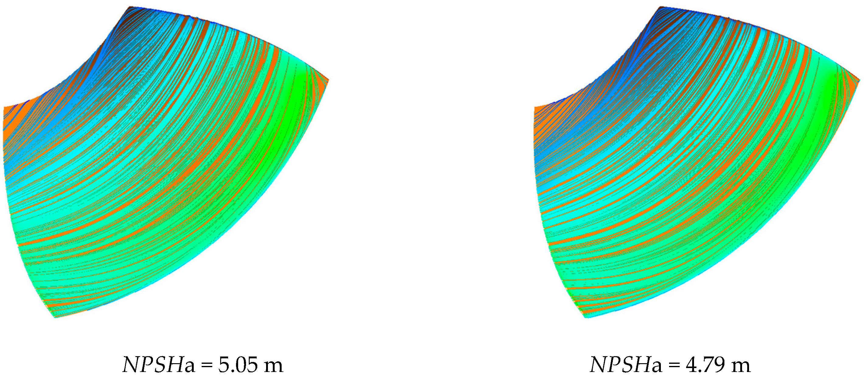
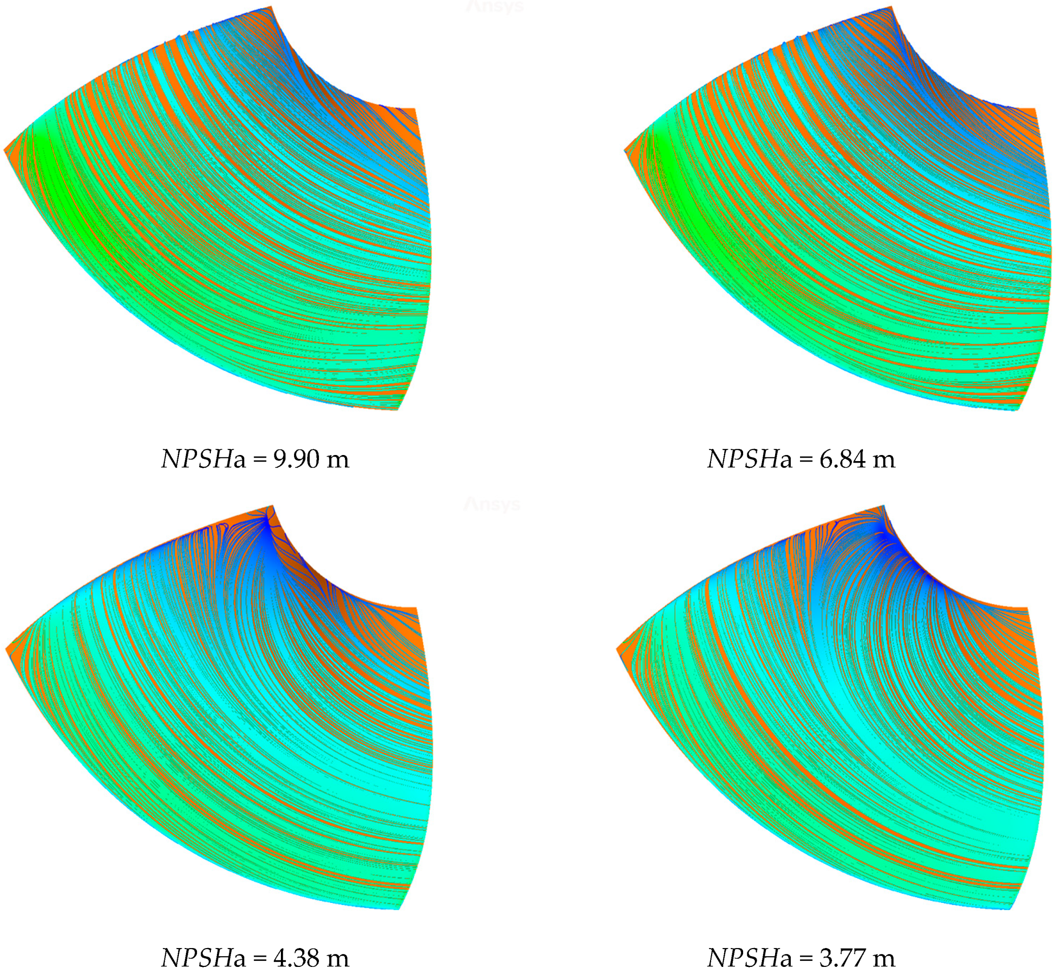
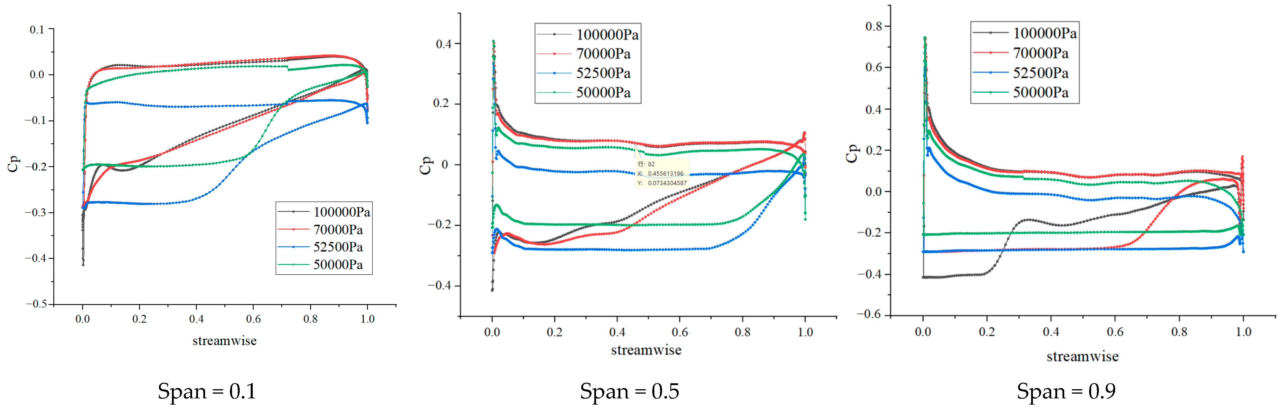
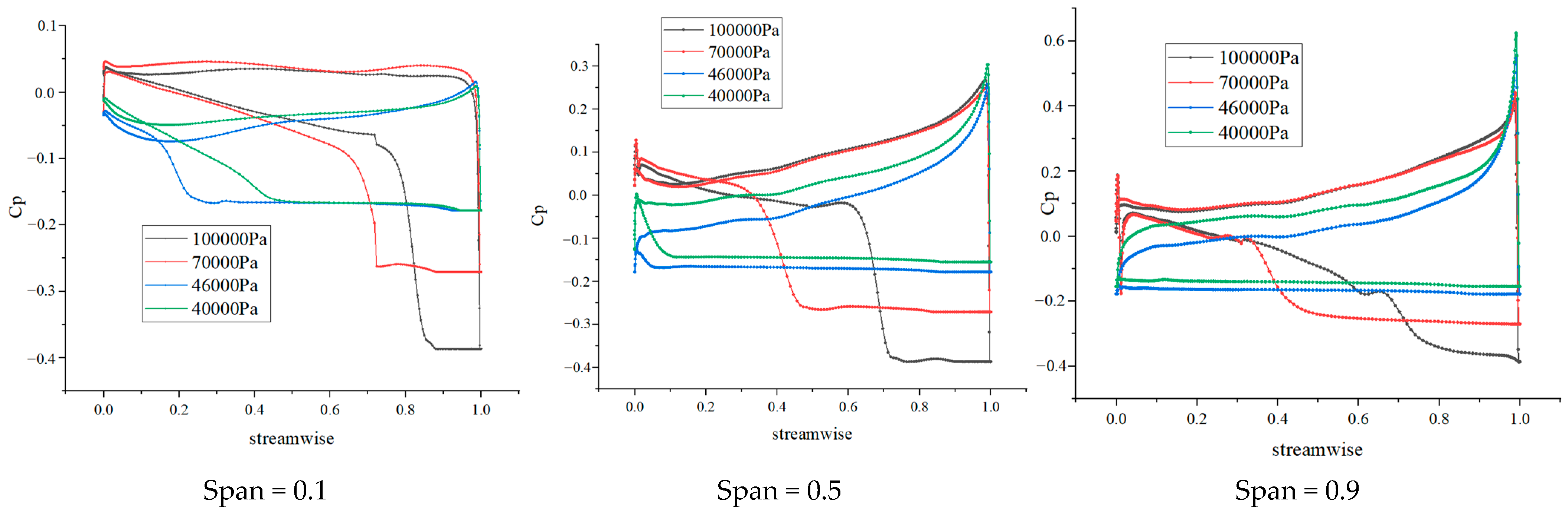
3.2.2. Impeller Blade Surface Flow Analysis

To further investigate the hydrodynamics of the integrated pump gate, we plotted the distribution of cavity on the impeller for bidirectional operation at different NPSHa. Figure 8 shows selected vapor volume fraction distribution under different NPSHa. When the NPSHa = 10.04 m, cavitation predominantly occurs in a limited region near the top of the blades at the leading edges. The thickness of the cavitation layer attached on the blade appears to be quite thin. As the NPSHa decreases to 6.83 m, cavitation gradually develops from the suction side toward the hub. At this juncture, cavitation occurs at the upper portion of the blade along the streamline towards the trailing edge. Simultaneously, it also develops along the spanwise direction towards the leaf root. It primarily extends along a third of the impeller chord, with a noticeable increase in the cavitation area at the top of the impeller. By examining the curve graph illustrating the characteristics of gasification, it becomes apparent, at an NPSHa of 5.05 m, the pump reaches the state of critical cavitation, leading to a significant decline in hydraulic performance. The top region of the suction surface is almost completely covered by the cavitation layer, and approximately four-fifths of the suction surface is affected as well. The cavitation layer thickens further, ultimately forming a noticeable void. At an inlet pressure of 4.79 m, the development of cavitation is less apparent when compared to the previous state, but still exhibits a very serious cavitation, primarily reflected in an increase in thickness and a small extension towards the hub.
The inlet pressures selected in Figure 9 are 100,000 Pa, 70,000 Pa, 46,000 Pa, and 40,000 Pa. According to the erosion characteristics curve and air bubble diagram, when the inlet pressure is 100,000 Pa, corresponding to an NPSHa of 9.90 m, the blade pressure of the axial flow pump is exceedingly high, leading to cavitation primarily occurring at the top region of the blade and the entrance edge on the suction side. The thickness of the cavitation is relatively thin. When the inlet pressure decreases to 70,000 Pa, NPSHa decreases to 6.84 m. At this point, the impeller experiences gradual development of cavitation along the suction surface and towards the hub. The cavitation develops along the chord length up to the halfway point on the impeller’s suction side, and the cavitation area at the top of the impeller further expands. When the inlet pressure decreases to 46,000 Pa, corresponding to an NPSHa of 4.38 m, the impeller reaches the cavitation critical point. The erosion on the top of the suction side blades covers three-quarters of the blade surface, and the hub erosion along the chord length continues to develop. When the inlet pressure decreases to 40,000 Pa, although there is no significant change in cavitation development, the thickness of the cavitation layer increases, and there is a slight expansion along the chord length.
Figure 10 and Figure 11 illustrate the flow distribution in the suction and pressure surfaces of the impeller when the integrated pump is bidirectional at different inlet pressures. From Figure 10, it can be observed that under forward operation at an NPSHa of 10.04 m, the fluid in the inlet section experiences cavitation effects, leading to turbulent flow at the impeller’s suction surface. This results in the formation of a small area of low velocity, as well as the occurrence of recirculation and lateral jets. The starting position of the lateral jet is located on the side close to the hub at the leading edge of the impeller’s suction surface. When the NPSHa drops to 6.84 m, the low-speed zone occupies one-quarter of the blade area. Compared to previous conditions, the return flow and lateral jet range on the suction surface of the blade have increased, with their starting positions shifting towards the hub side. When the net positive suction head available (NPSHa) is further reduced to 5.05 m, approximately half of the blade area is covered by a low-velocity region, and a low-pressure zone extends from the blade root to the blade outlet. At this time, the occurrence of recirculation on the suction surface in the inlet section is almost nonexistent. The lateral jet position continues to move to the top of the blade. Under the NPSHa of 4.79 m, the low-velocity region on the suction surface covers half of the blade’s surface area. The mid-low-speed zone extends along the blade height toward the top of the blade, and the recirculation phenomenon appears near the top of the blade.
From Figure 11, it is evident that there is no significant change in the pressure surface streamline under NPSHa of 6.84 m and 9.90 m. However, as the NPSHa further drops to 4.38 m, a low-velocity region appears from the top of the blade to the trailing edge of the pressure surface. This low-velocity region remains similar when the NPSHa is 3.77 m. There are two primary factors that contribute to the formation of the low-speed region at this moment. There is a significant occurrence of cavitation on the suction surface of the impeller, coupled with the presence of backflow phenomena.
Figure 12 and Figure 13 show the flow distribution of the integrated pump gate. It can be inferred from Figure 12 that during forward operation at an inlet pressure of 100,000 Pa, the suction surface exhibits only a localized region of reduced velocity, along with occurrences of backflow and jetting. When the inlet pressure reaches 70,000 Pa, the covered area of the low-velocity region extends beyond half of the surface, with the mid-low-pressure region extending along the blade root towards the hub. When the inlet pressure reduced to 52,500 Pa, corresponding to an NPSHa of 5.05 m, the low-velocity region on the impeller blade’s suction surface covers two-thirds of the blade’s surface, and the lateral jetting continues to move towards the blade tip. When the inlet pressure reduces to 50,000 Pa, corresponding to an NPSHa of 4.79 m, the coverage area of the low-velocity region remains relatively unchanged, while the mid-low-velocity region extends towards the blade tip in the direction of the blade height, and backflow occurs at the blade tip.
Figure 13 shows the streamline distribution when the integrated pump gate is running in reverse. It can be observed that when the NPSHa is at 9.90 m and 6.84 m, the impeller vane pressure surface streamline does not exhibit any significant turbulence. However, when the NPSHa further drops to 4.38 m, a low-speed area appears on the blade pressure surface, mainly in the top of the blade to the trailing edge range. The range of the low-speed region is approximately equivalent when NPSHa decreases to 3.77 m, compared to when NPSHa is around 4.38. The main reason for the formation of this low-speed zone is due to the impeller blade suction surface producing a large area of cavitation and recirculation.
Figure 14 and Figure 15 show the distribution of cavities on the blade section of the impeller. From Figure 14, it can be observed that the cavities within the impeller are not pronounced when the inlet pressure is at 100,000 Pa and 70,000 Pa (where NPSHa is 10.04 m and 6.84 m, respectively). When it decreases to 52,500 Pa, the NPSHa at this point being 5.05 m, an attached cavity appears on the suction surface of the impeller blade. At this time, the top region of the impeller is almost completely covered by the cavity, with four-fifths of the suction surface of the area also covered. As the pressure drops to 50,000 Pa, the NPSHa at which point is 4.79 m, the cavity thickness increases, indicating that the pump has progressed to a severe cavitation state.
Moving on to Figure 15, during reverse operation, the suction surface of the impeller blades experiences cavitation chamber at 9.90 m of NPSHa. The development of these cavitation chamber gradually unfolds as the inlet pressure continuously declines. The cavitation chambers reach their maximum extent at 4.38 m, with the cavitation on the leading edge of the suction surface covering three-quarters of the blade’s surface area. The air pockets thicken further, and the cavitation at the hub extends along the chord. The pump has now reached a critical stage of cavitation.
Figure 16 and Figure 17 show the distribution of blade surface pressure coefficient under bidirectional operation. The horizontal coordinate indicates the blade surface chordal position coefficient, wherein 0 indicates the leading edge of the impeller blade, and 1 indicates the trailing edge of the impeller blade. The vertical coordinate indicates the blade surface pressure coefficient Cp, which is used to describe the surface load variation of the blade pressure surface and suction surface, with its equation shown below. Each column in the figure indicates different blade heights, spanning 0.1, 0.5, and 0.9. The figure includes the blade surface pressure coefficient at different inlet pressures for each flow condition.
C p = P P 1 0.5 ρ π n D R
In the above equation, P is the impeller vane surface pressure, Pa; P 1 is the average pressure of the pressure measuring surface, Pa; D R is the impeller diameter, 0.29 m; n is the integrated pump gate speed, 1450 r/min.
From Figure 16 and Figure 17, it can be found that the pressure coefficient of the suction surface fluctuates more, and the gradient of the leading edge of the blade is more obvious. In this phenomenon, the closer the position to the rim, the greater the gradient of the pressure coefficient. This indicates that the location of the load is mainly distributed in the leading edge, and the changes are mainly generated in the pressure surface rim.
Based on the aforementioned analysis, it can be concluded that as the inlet pressure decreases and the span increases, the location of the pressure coefficient’s abrupt change moves towards the trailing edge along the blade’s spanwise direction. This phenomenon is in perfect accordance with the distribution of cavitation on the impeller blade surface. Therefore, it can be inferred that the formation of cavitation is the fundamental cause behind the fluctuation in pressure on the impeller blade.

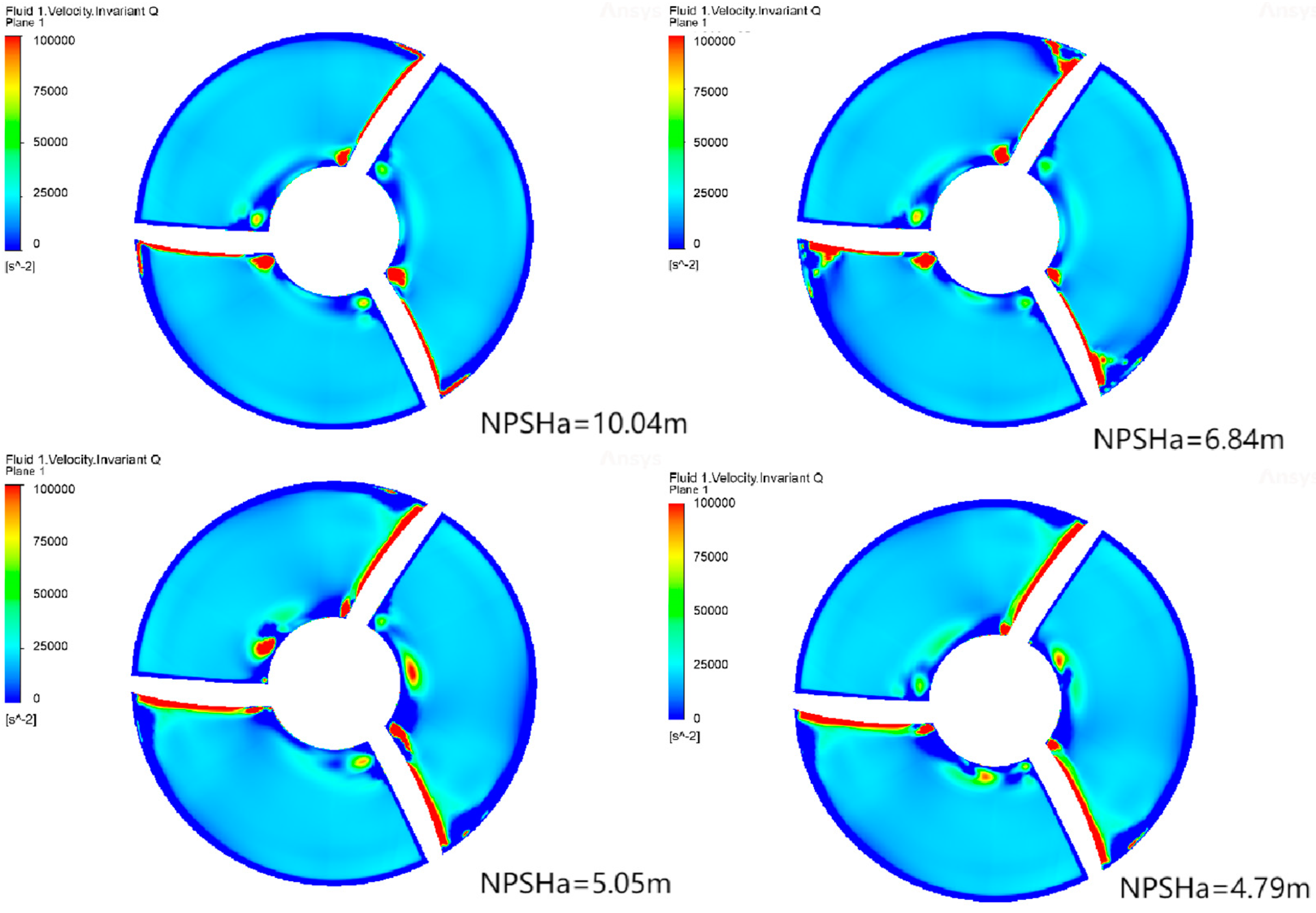
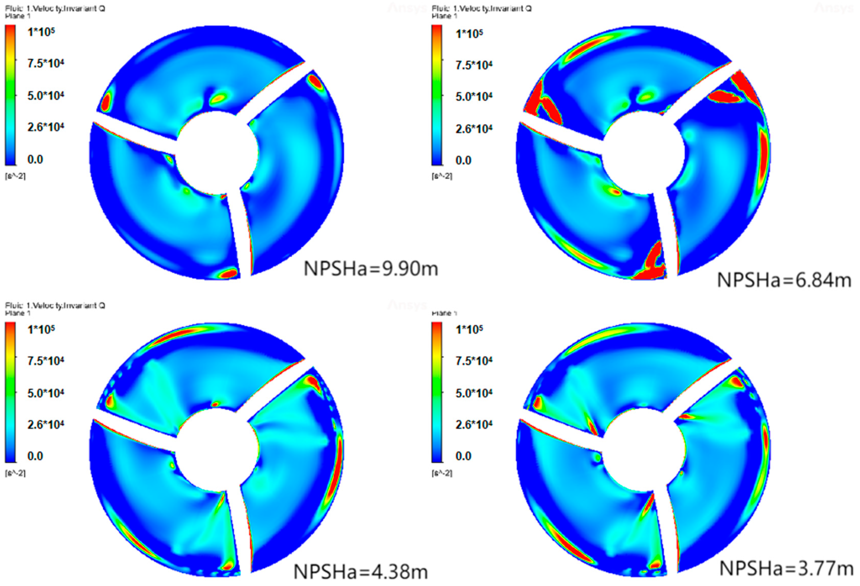
3.2.3. Vortex Analysis of Impeller

Figure 18 and Figure 19 depict the structure of the planar vortex under bidirectional operation. As observed in the figures, the vortex structure mainly appears in the rim region, and the vortex structure in the reverse operation is larger than that in the forward operation. The reason for the vortex structure may be the low-speed area caused by cavitation. There is also a possibility that the vortex structure is caused by the emergence of the blade top gap.

4. Conclusions

This paper presents the first numerical simulation of bidirectional operation of an integrated pump gate to study its cavitation position and vortex structure. The subsequent optimized design of the integrated pump gate is also discussed, which provides support and predictions for the occurrence of cavitation during actual operation.
The numerical simulation and post-processing analysis of the bidirectional operation of the integrated pump gate provide valuable insights into its cavitation position and vortex structure. The results demonstrate that cavitation first appears near the top of the vane at the leading edge of the vane suction. The reduction of inlet pressure induces cavitation in two directions, towards the hub and trailing edge, resulting in a sudden pressure drop at the suction surface of the blade. The decrease in inlet pressure also causes the lateral jet position of the impeller blade suction surface to move towards the outlet position, driven by the inverse pressure gradient on the blade suction surface.
Moreover, as the pressure continues to decrease, the presence of cavitation bubbles becomes noticeable, leading to severe cavitation within the pump. Further reduction in the inlet pressure results in the development of the cavitation vacuole, particularly in terms of its thickness.
These findings provide valuable insights into the cavitation characteristics and flow patterns within the integrated pump gate. The study lays the foundation for optimizing the design of bidirectional operation in integrated sluice gate pumps for future engineering applications.

Author Contributions

Investigation, H.L.; Writing—original draft, H.W.; Software, Z.Z.; Project administration, R.Z.; Writing—review & editing, Y.L. All authors have read and agreed to the published version of the manuscript.

Funding

This research was funded by the China Postdoctoral Science Foundation Funded Project [Grant No. 2019M651734, 2023M733355], Jiangsu University Youth Talent Development Program [2020], the Chunhui Program Cooperative Scientific Research Project of the Ministry of Education, Research Project of State Key Laboratory of Mechanical System and Vibration [MSV202203], Natural Science Foundation of China [Grant No. 51906085, Grant U20A20292], Jiangsu Province Innovation and Entrepreneurship Doctor Project [2019]. This research was also supported by the Open Project Program of Shandong Marine Aerospace Equipment Technological Innovation Center, Ludong University [Grant No. MAETIC202211].

Data Availability Statement

The data that support the findings of this study are available from the corresponding authors upon reasonable request.

Conflicts of Interest

The authors declare no conflict of interest.

References

  1. Zhao, Q. Analysis of the characteristics and application advantages of integrated pump gate. Mech. Electr. Inf. 2020, 52–53. (In Chinese) [Google Scholar] [CrossRef]
  2. Tan, Y. Types and Comparative Analysis of Drainage Gate Stations. Shaanxi Water Conserv. 2021, 246, 242–244. (In Chinese) [Google Scholar] [CrossRef]
  3. Song, J. Application of integrated pump and gate in the management of Fuzhou inland water system. Fujian Constr. 2018, 140–142. (In Chinese) [Google Scholar]
  4. Guo, M.; Chen, Z.; Lee, Y.; Choi, Y.-D. Air Entrainment Flow Characteristics of Horizontal and Elbow Type Gate Pump-Sump Models. KSFM J. Fluid Mach. 2019, 22, 54–61. [Google Scholar] [CrossRef]
  5. Li, H.L.; Fu, P. Study on issues related to pump selection and installation of Xinquansi pump station. Hunan Hydropower 2020, 85–87. (In Chinese) [Google Scholar] [CrossRef]
  6. Li, M. Design and technical point analysis of integrated pump gate. Mech. Electr. Inf. 2020, 126–127. (In Chinese) [Google Scholar] [CrossRef]
  7. Jin, L. Development of a submersible gate pump with built-in impeller. Pump Technol. 2015, 23–26. (In Chinese) [Google Scholar]
  8. Wei, Z. Study on the application of pump and gate engineering in drainage and flood control system. Shaanxi Water Conserv. 2021, 81–83. (In Chinese) [Google Scholar]
  9. Kentaro, F.; Yu, K.; Hiroaki, F. Validation of Inundation Damage Reduction by a Pump Gate with the New Type of Horizontal Axial Submersible Pump. JDR 2021, 16, 381–386. [Google Scholar]
  10. Sun, X.; Liu, S.; Manickam, S.; Tao, Y.; Yoon, J.Y.; Xuan, X. Intensification of biodiesel production by hydrodynamic cavitation: A critical review. Renew. Sustain. Energy Rev. 2023, 179, 113277. [Google Scholar] [CrossRef]
  11. Brennen, C.E. Cavitation and Bubble Dynamics; Oxford University Press: Oxford, UK, 1995. [Google Scholar]
  12. Yang, F.; Jin, Y.; Liu, C.; Tang, F.; Cheng, L.; Yang, H. Performance test and numerical analysis of bi-directional submersible cross-flow pump device. J. Agric. Eng. 2012, 28, 60–67. (In Chinese) [Google Scholar] [CrossRef]
  13. Liu, J.; Lu, W.; Zhou, B.; Sun, C.; Xia, H. Experimental study on the external characteristics of fully-crossflow pumping device--Taking Longkungou North Stormwater Drainage Pumping Station as an Example. China Rural. Water Conserv. Hydropower 2022, 1–14. Available online: https://kns.cnki.net/kcms/detail/detail.aspx?FileName=ZNSD202208028&DbName=CJFQ2022 (accessed on 23 July 2023). (In Chinese).
  14. Wu, W. Study on Cavitation and Gap Leakage Vortex Characteristics of Axial Water Jet Propulsion Pump; Xi’an University of Technology: Xi’an, China, 2021. (In Chinese) [Google Scholar] [CrossRef]
  15. Long, Y.; An, C.; Zhu, R.; Chen, J. Research on hydrodynamics of high velocity regions in a water-jet pump based on experimental and numerical calculations at different cavitation conditions. Phys. Fluids 2021, 33, 045124. [Google Scholar] [CrossRef]
  16. Yun, L.; Yan, Z.; Jianping, C.; Rongsheng, Z.; Dezhong, W. A cavitation performance prediction method for pumps: Part2-sensitivity and accuracy. Nucl. Eng. Technol. 2021, 53, 3612–3624. [Google Scholar] [CrossRef]
  17. Yun, L.; Rongsheng, Z.; Dezhong, W. A cavitation performance prediction method for pumps PART1-Proposal and feasibility. Nucl. Eng. Technol. 2020, 52, 2471–2478. [Google Scholar] [CrossRef]
  18. Qiu, N.; Zhu, H.; Long, Y.; Zhong, J.; Zhu, R.; Wu, S. Assessment of Cavitation Erosion in a Water-Jet Pump Based on the Erosive Power Method. Scanning 2021, 2021, 5394782. [Google Scholar] [CrossRef]
  19. Xie, C.; Xuan, W.; Feng, A.; Sun, F. Analysis of Hydraulic Performance and Flow Characteristics of Inlet and Outlet Channels of Integrated Pump Gate. Water 2022, 14, 2747. [Google Scholar] [CrossRef]
  20. Xie, C.; Fu, T.; Xuan, W.; Bai, C.; Wu, L. Optimization and Internal Flow Analysis of Inlet and Outlet Horn of Integrated Pump Gate. Processes 2022, 10, 1753. [Google Scholar] [CrossRef]
  21. Wang, Z.Y.; Cheng, H.Y.; Ji, B.; Peng, X.X. Numerical investigation of inner structure and its formation mechanism of cloud cavitating flow. Int. J. Multiph. Flow 2023, 165, 104484. [Google Scholar] [CrossRef]
  22. Wang, Y. Research on Internal Cavitation Flow Characteristics and Performance Improvement of Turbopump Inducer. Master’s Thesis, Beijing University of Technology, Beijing, China, 2021. [Google Scholar] [CrossRef]
  23. Zhang, G.; Zhang, D.; Ge, M.; Petkovšek, M.; Coutier-Delgosha, O. Experimental investigation of three distinct mechanisms for the transition from sheet to cloud cavitation. Int. J. Heat Mass Transf. 2022, 197, 123372. [Google Scholar] [CrossRef]
  24. Zhang, G.; Khlifa, I.; Fezzaa, K.; Ge, M.; Coutier-Delgosha, O. Experimental investigation of internal two-phase flow structures and dynamics of quasi-stable sheet cavitation by fast synchrotron X-ray imaging. Phys. Fluids 2020, 32, 113310. [Google Scholar] [CrossRef]
  25. Ge, M.; Petkovšek, M.; Zhang, G.; Jacobs, D.; Coutier-Delgosha, O. Cavitation dynamics and thermodynamic effects at elevated temperatures in a small Venturi channel. Int. J. Heat Mass Transf. 2021, 170, 120970. [Google Scholar] [CrossRef]
  26. Ge, M.; Manikkam, P.; Ghossein, J.; Subramanian, R.K.; Coutier-Delgosha, O.; Zhang, G. Dynamic mode decomposition to classify cavitating flow regimes induced by thermodynamic effects. Energy 2022, 254, 124426. [Google Scholar] [CrossRef]
  27. Ge, M.; Zhang, G.; Petkovšek, M.; Long, K.; Coutier-Delgosha, O. Intensity and regimes changing of hydrodynamic cavitation considering temperature effects. J. Clean. Prod. 2022, 338, 130470. [Google Scholar] [CrossRef]
  28. Ge, M.; Sun, C.; Zhang, G.; Coutier-Delgosha, O.; Fan, D. Combined suppression effects on hydrodynamic cavitation performance in Venturi-type reactor for process intensification. Ultrason. Sonochemistry 2022, 86, 106035. [Google Scholar] [CrossRef]
  29. GB/T 3216-2006/ISO 9906:2012; Rotodynamic Pumps—Hydraulic Performance Acceptance Tests—Grades 1, 2 and 3. AQSIQ: Beijing, China, 2019.
Figure 1. Diagram of the integrated pump gate.
Energies 16 06784 g001
Figure 2. Three-dimensional model of diffuser/impeller.
Energies 16 06784 g002
Figure 3. Grid independence analysis.
Energies 16 06784 g003
Figure 4. Grid division.
Energies 16 06784 g004
Figure 5. Hydraulic performance curve of forward operation.
Energies 16 06784 g005
Figure 6. Hydraulic performance curve of reverse operation.
Energies 16 06784 g006
Figure 7. Cavitation characteristic curves at bidirectional operation.
Energies 16 06784 g007
Figure 8. Vapor volume fraction distribution at forward operation.
Energies 16 06784 g008
Figure 9. Vapor volume fraction distribution at reverse operation.
Energies 16 06784 g009
Figure 10. Streamline distribution of blade’s suction surface with different inlet pressures under forward operation.
Energies 16 06784 g010
Figure 11. Streamline distribution of blade’s pressure surface with different inlet pressures under forward operation.
Energies 16 06784 g011aEnergies 16 06784 g011b
Figure 12. Streamline distribution of blade’s suction surface with different inlet pressures under reverse operation.
Energies 16 06784 g012aEnergies 16 06784 g012b
Figure 13. Streamline distribution of blade’s pressure surface with different inlet pressures under reverse operation.
Energies 16 06784 g013
Figure 14. Contours of vapor volume fraction at different pressures under forward operation.
Energies 16 06784 g014
Figure 15. Contours of vapor volume fraction at different pressures under reverse operation.
Energies 16 06784 g015
Figure 16. Distribution of blade’s surface pressure coefficient under forward operation.
Energies 16 06784 g016
Figure 17. Distribution of blade’s surface pressure coefficient under reverse operation.
Energies 16 06784 g017
Figure 18. Schematic diagram of two-dimensional impeller vortex structure under forward operation.
Energies 16 06784 g018
Figure 19. Schematic diagram of two-dimensional impeller vortex structure under reverse operation.
Energies 16 06784 g019
Table 1. Grid division of calculation area.
Calculation AreaInlet PipeImpellerDiffuserOutlet Pipe
Number of grids1,934,4003,753,0363,878,1001,917,332
Number of nodes1,972,7543,895,7764,034,8901,956,058
Disclaimer/Publisher’s Note: The statements, opinions and data contained in all publications are solely those of the individual author(s) and contributor(s) and not of MDPI and/or the editor(s). MDPI and/or the editor(s) disclaim responsibility for any injury to people or property resulting from any ideas, methods, instructions or products referred to in the content.

