Article

Study on the Coupling Effect of Stress Field and Gas Field in Surrounding Rock of Stope and Gas Migration Law

1
College of Safety Science and Engineering, Henan Polytechnic University, Jiaozuo 454150, China
2
Sinopec Fuel Oil Sales Co., Ltd., Fujian Branch, Fuzhou 350000, China
*
Author to whom correspondence should be addressed.
Energies 2023, 16(18), 6672; https://doi.org/10.3390/en16186672
Submission received: 2 August 2023 / Revised: 9 September 2023 / Accepted: 15 September 2023 / Published: 18 September 2023

Abstract

:
In the process of working face mining, the permeability of the coal seam and the crack evolution characteristics of overlying strata are very important for efficient gas drainage. In this study, the distribution characteristics of the stress field and crack field in the working face and their relations are analyzed mainly by 3DEC numerical simulation. Furthermore, combined with the on-site measurement of coal seam stress, gas pressure, and gas seepage in front of the working face and the gas seepage in overlying strata before and after mining, the coupling effect of stress field and gas field and the law of gas migration and distribution in the working face are deeply explored. The results show that the changing trend of gas seepage and gas pressure is controlled by the stress change of the working face, and with the increase of stress, gas pressure and gas seepage also increase. The peak position of gas pressure is the farthest from the coal wall, about 22.5~25 m, followed by the peak of stress and gas seepage. When the permeability of coal and rock mass increases, the gas seepage increases and the gas pressure decreases. The coal seam stress and gas seepage in the working face and gas seepage in the overlying strata fracture zone along the tailgate side are generally greater than those on the headgate side, but the gas pressure is the opposite. Mining cracks and strata separation provide a good channel and space for gas migration and accumulation. Along the strike and tendency of the working face, gas is mainly concentrated in the overlying strata crack space above the separation zone and the roof and overlying strata crack space on the side of the tailgate, respectively. Based on this, the directional borehole gas drainage technology and borehole layout scheme in the fractured zone are put forward, which effectively reduce the gas concentration in the working face by 30~36%.

1. Introduction

Coal mine gas disasters mainly include coal and rock gas dynamic disasters, gas explosions, gas emissions, gas suffocation, and so on. This kind of disaster seriously threatens the safety of production, and it is also the focus of many scholars. Over the years, various coal-mining countries have done a lot of research on the mechanism and prevention technology (Gas drainage) of gas disasters and also achieved some research results [1,2,3,4,5,6,7,8,9]. According to the existing research results, it can be known that the stress redistribution of surrounding rock caused by mining has great influences on the development of cracks in the roof and overlying strata, gas desorption, and seepage in coal seams. In the process of coal mining, the mining stress changes, and the overlying strata move and fracture under the influence of mining, accompanied by the development and evolution of mining cracks [10,11,12], and then the gas migrates in the cracks [13]. Therefore, it is the foundation and key to studying the stress distribution characteristics and crack evolution laws of the surrounding rock.
For the stress distribution of mining surrounding rock and the evolution law of overlying strata cracks, Professor Qian and Professor Li [14,15,16] put forward such overlying strata shapes as “O” rings, elliptical throwing belts, and rectangular terrace belts with rounded corners of mining cracks, which provided a theoretical basis for the study of overlying strata in stope. Lin et al. used 3DEC numerical simulation software to analyze the distribution law of stress and displacement of mining overlying strata and study the evolution characteristics of pressure relief gas storage areas [17]. Xu et al. comprehensively use physical similarity simulation and 3DEC numerical simulation to explore the failure characteristics, stress distribution characteristics, and crack evolution laws of overlying strata. Furthermore, the evolution characteristics of coal body cracks in the working face under the influence of mining are studied [18]. Wang et al. used physical similarity simulation and PFC numerical simulation to study the failure characteristics, crack development, and porosity change characteristics of overlying strata so as to determine the development height of the gas-conducting fractured zone of overlying strata [19]. Li et al. comprehensively used physical similarity simulation and UDEC numerical simulation to study the failure characteristics, crack evolution, and pressure relief characteristics of roofs and overlying strata in protective layer mining. It also shows that protective layer mining can effectively reduce gas pressure and is beneficial to gas release [20].
For the coupling relationship between mining stress field and gas field and the law of gas migration, Zhao et al. established the coupling model of coal seam stress field, damage field, gas diffusion field, and seepage field and carried out numerical simulations on the coal seam mining process [21]. At the same time, the evolution laws of gas pressure, coal seam stress, and permeability under different conditions are analyzed. Zhang et al. studied the development height of fractured zones in overlying strata by physical experiment and 3DEC numerical simulation and verified it by the gas drainage method. Affected by mining, the stope stress and gas migration are constantly changing, and the stable overlying strata crack is an effective channel for gas migration to ensure efficient gas extraction [22]. Zhang et al. analyzed the principle of high-level directional borehole gas drainage technology, explored the influence of fractured zones in goaf on gas drainage effect, and made it clear that the gas drainage amount is closely related to the evolution law of overlying strata cracks [23]. In order to study the characteristics of gas migration in anisotropic coal seams, Nian et al. established the Coupled Anisotropic Dual-Porosity Model and analyzed the influence of permeability anisotropy and working face stress on gas pressure, gas drainage volume, and effective drainage area [24]. At present, scholars have comprehensively used a variety of methods or monitoring equipment to effectively obtain the evolution laws of overlying strata crack fields, stress fields, displacement fields, deformation, gas seepage, and gas pressure, thus guiding the design and application of directional boreholes in gas drainage [25,26,27]. In addition, according to the dynamic change of gas drainage concentration, it can also be directly used to judge the stress distribution characteristics of the working face [28].
Previous research work has achieved fruitful results in the crack evolution and failure movement of overlying strata induced by coal seam mining, forming a recognized theoretical system. However, the coupling relationship between mining stress fields and gas fields and the law of gas migration are complex and still need further study. In this paper, the stress distribution characteristics of stope, the evolution law of overlying strata cracks, and the evolution characteristics of the pressure relief gas accumulation area are studied by using 3DEC numerical simulation software. Combined with the on-site measurement of coal seam stress, gas pressure, and gas seepage in front of the working face and the gas seepage in overlying strata before and after mining, the coupling effect of stress field and gas field and the law of gas migration and distribution in the working face are deeply explored. Based on this, the gas drainage technology and directional borehole layout scheme in the fractured zone are put forward, and the experimental working face is designed and applied in engineering. This study further enriches the relevant theoretical system of gas migration and distribution under the coupling effect of multiple fields in the working face and provides a reference for gas drainage technology for pressure relief. So as to accelerate the realization of safe and efficient coal and gas co-mining in high-gas mines.

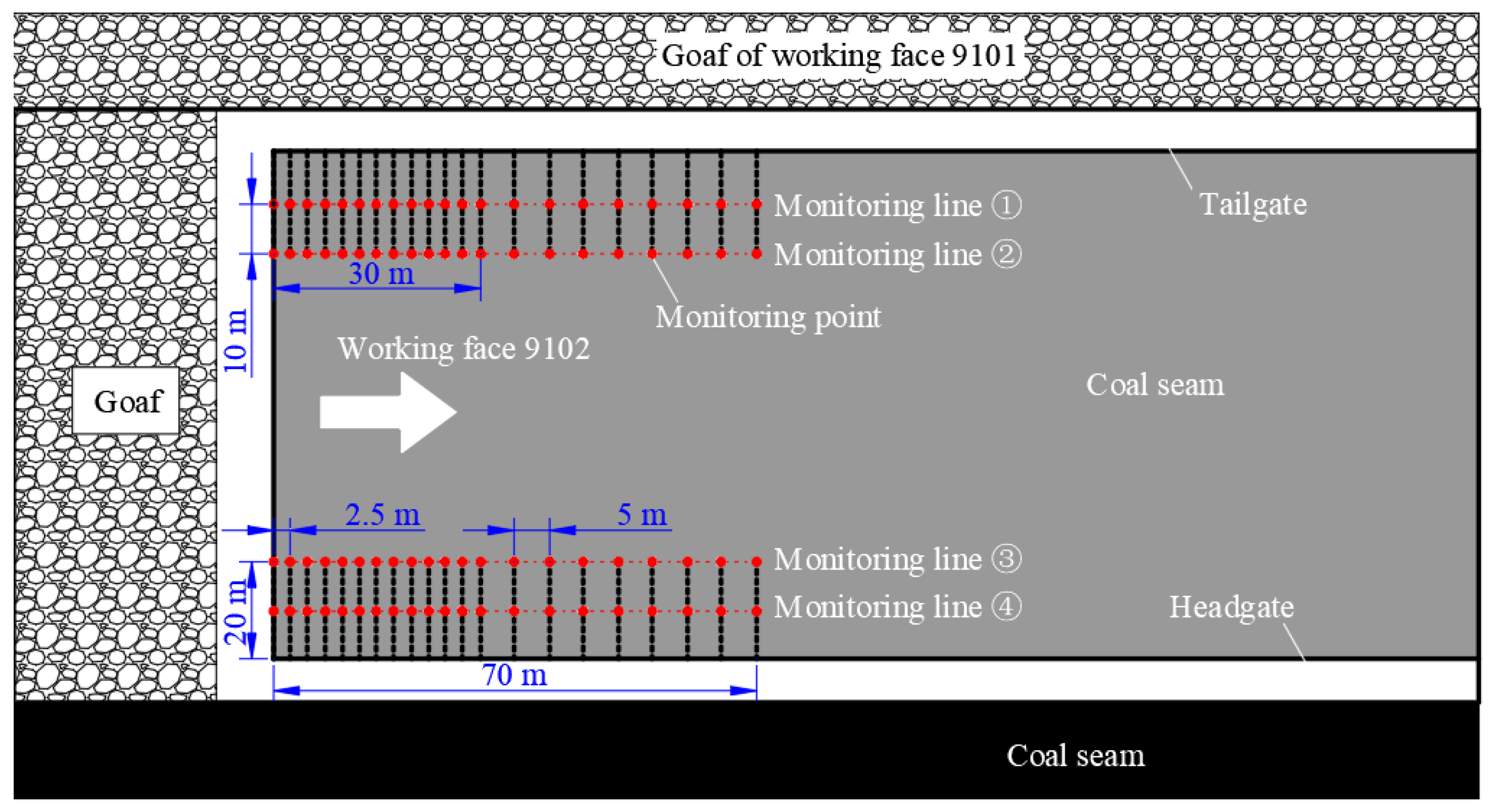
2. Distribution Characteristics of Mining Stress in Working Face

Mining will cause stress redistribution in the surrounding rock of the stope. With the advance of the working face, the roof collapses, and the gangue behind the goaf is gradually compacted. The “horizontal three zones” as shown in Figure 1a are formed in the working face and mainly involve the coal wall abutment pressure zone (I), the roof separation zone (II), and the recompression zone (III). At the same time, roof caving and overlying strata subsidence will also form “vertical three zones”, namely the caving zone, fractured zone, and continuous bending zone [29,30]. With the disturbance of mining, when the stress reaches the secondary balance, the stress-stable area (A), the stress-concentration area (B), and the stress-relaxation area (C), as shown in Figure 1b, are respectively formed in the front and back of the working face. The coal wall in front of the working face supports most of the load of the fractured zone above the working face and its overlying strata, which causes the advance abutment pressure in front of the working face to be much greater than that behind the working face. At the same time, the working face keeps advancing, and the coal wall is also in the process of dynamically moving in the advancing direction, so the abutment pressure before and after the working face is in a moving state. Because the fractured zone has formed an arch-shaped balanced structure supported by the coal wall and the caving gangue in the goaf, the working face is in the range of the stress reduction zone. With the working face advancing forward, roof caving, and overlying strata subsidence, the gangue in the goaf behind the working face is compacted again, and its stress will further increase. When the gangue in goaf is compacted to a stable state, its stress will also be in a stable state.

3. Numerical Simulation of Failure Field and Stress Field in Working Face

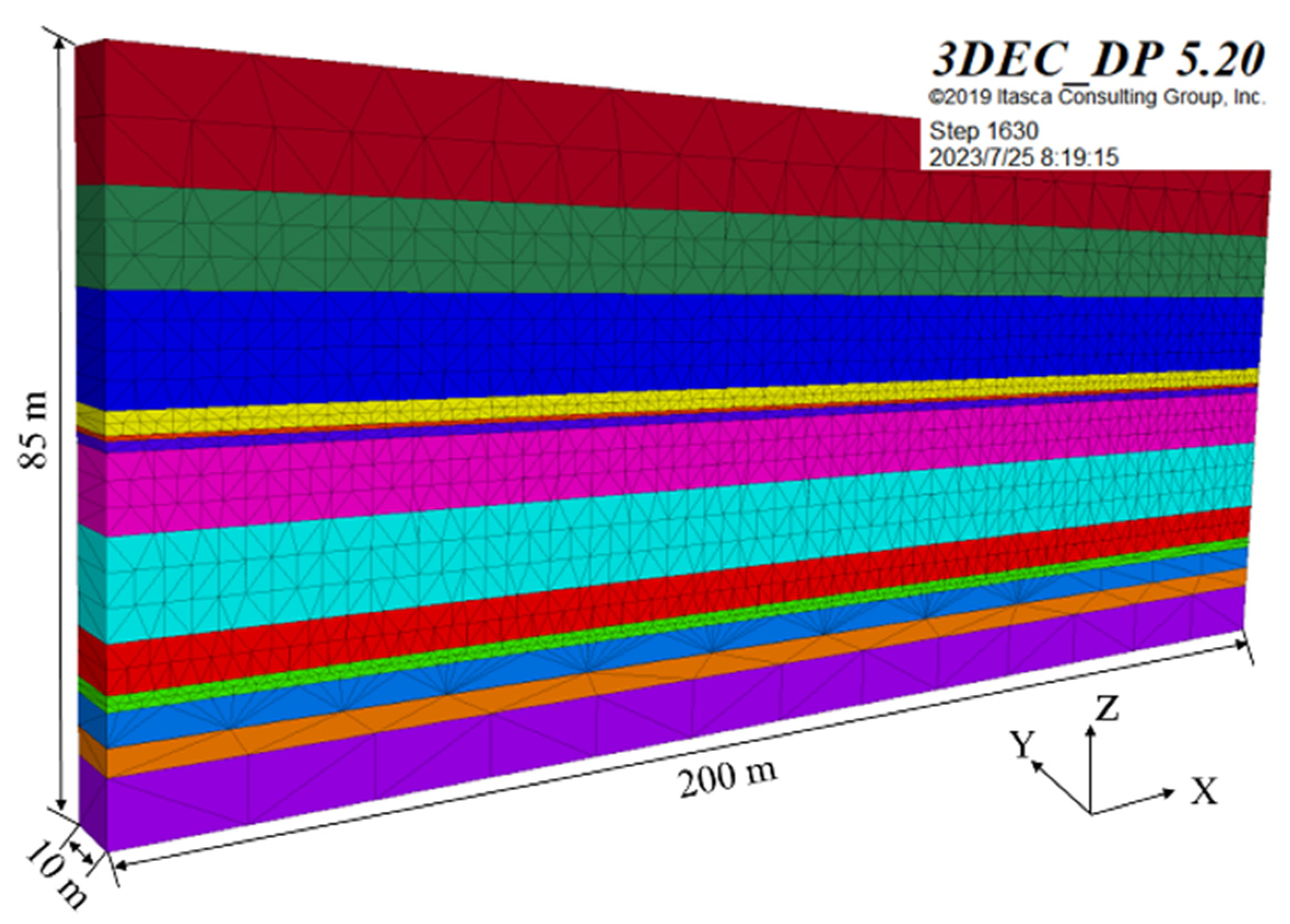
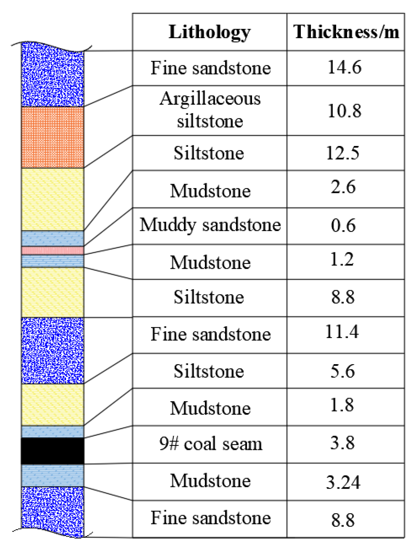
3.1. Numerical Model Establishment

At present, the main coal seam in a mine in Shanxi is 9# coal seam. The dip angle of the coal seam is about 2°, and it is a flat seam with a thickness of 2.53~4.28 m. The coal seam is relatively stable, with a simple structure and no special geological structure. This study is based on working face 9102, which is close to the goaf of working face 9101. The length of the working face is 180 m along the inclined direction, and it is mined forward along the strike. The average mining height of the working face is 3.8 m, and the buried depth is about 300 m, as shown in the specific coal seam histogram (Figure 2). The roadway layout with goaf-side entry retaining without coal pillars is adopted in this working face. The mining technology is longwall retreating fully-mechanized coal mining, and the roof is managed by the full caving method. Physical and mechanical parameters and joint mechanical parameters of coal and rock mass in the working face are shown in Table 1 and Table 2.
According to the conditions of working face 9102, the numerical model as shown in Figure 3 is established by using 3DEC numerical simulation software. The length (X direction), width (Y direction), and height (Z direction) of the model are 200 m, 10 m, and 85 m, respectively. 40-m coal pillars are set at both ends of the model to avoid boundary effects, and 120-m coal seam mining is simulated by advancing along the X direction. The boundary of the model is constrained by a fixed displacement, and the displacement and velocity are set to zero. At the same time, in order to simulate the rock mass load above the model to the surface, the equivalent vertical stress of 7.5 MPa is applied above the model. The elastic-plastic constitutive model based on the Mohr-Coulomb strength criterion is adopted for each stratum [17,18].

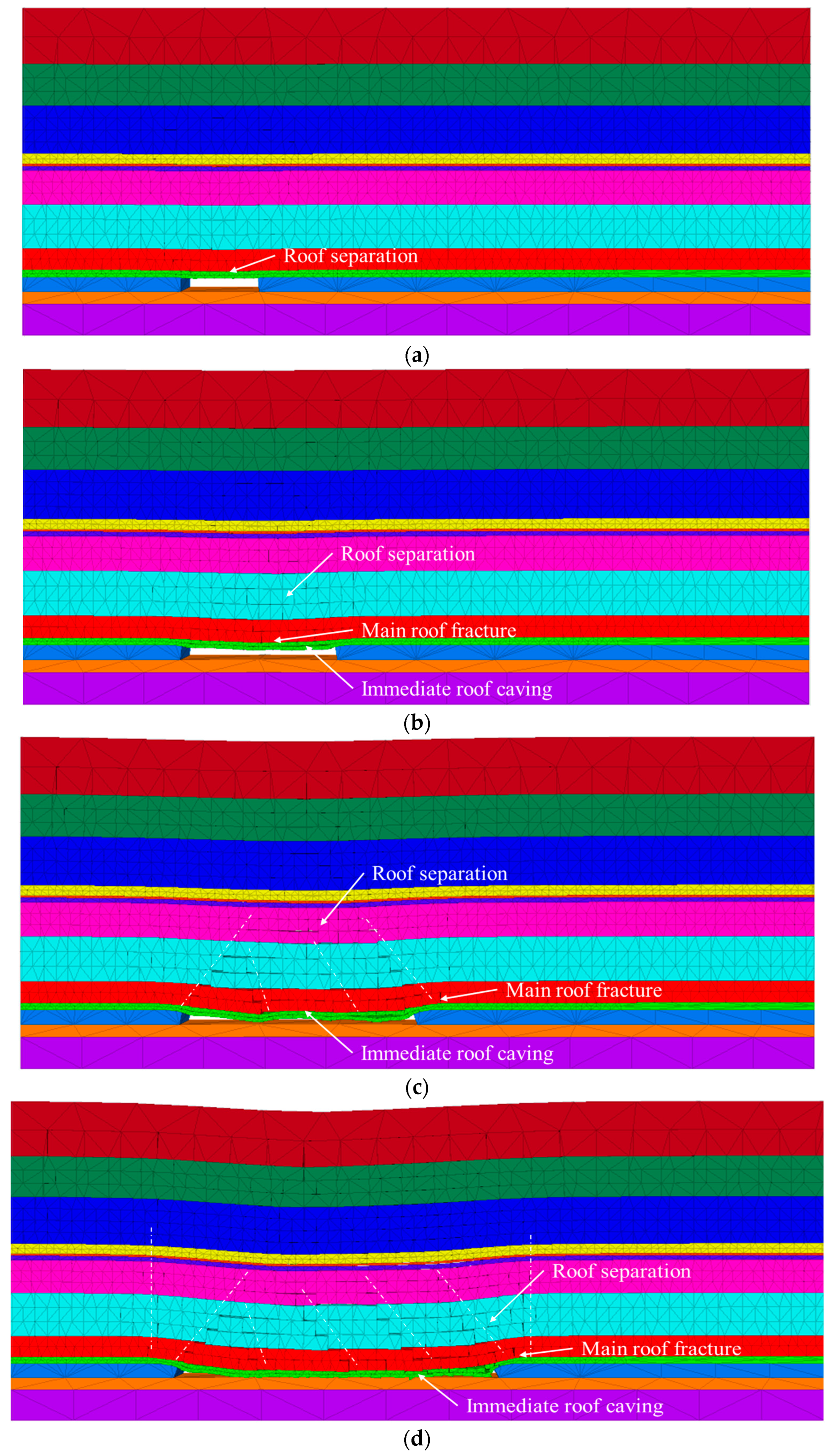
3.2. Failure Characteristics of Roof and Overlying Strata

The failure characteristics of the roof and overlying strata under different advancing lengths of working face are shown in Figure 4. When the working face advances 20 m forward, the immediate roof and the main roof only produce local separation phenomena, and the roof has not obviously failed at this time. When the working face advances 40 m, the immediate roof begins to be slightly failed and caving, and the main roof also fractures in the middle of the goaf. At the same time, an obvious separation occurred on the upper roof. When the working face advances 60 m, the immediate roof caves in a large range, and the main roof behind the working face also appears to have fracture instability. The main roof above the coal wall in the working face fractures, forming a stable masonry beam structure. The phenomenon of roof separation continues to spread to the upper roof. When the working face advances 80 m, the main roof periodically fractures with the working face advancing forward. At this time, the phenomenon of roof separation is intensified, accompanied by the subsidence of overlying strata. In addition, the roof and overlying strata vertically above the coal wall in front of the working face also failed, which was caused by the large-scale subsidence of the overlying strata. When the working face advances 100 m and 120 m, the failure of the roof and overlying strata is basically the same. With the continuous advance of the working face, the roof caving continues to extend to the overlying strata. At this time, the phenomenon of the roof separation zone (II) above the coal wall of the working face is more obvious.

3.3. Evolution Law of Cracks in Roof and Overlying Strata

Figure 5 shows the development of cracks in the roof and overlying strata under different advancing lengths of the working face, and the statistics of the crack development height and the number of vertical cracks are shown in Figure 6. When the working face advances 20 m forward, the cracks at the roof position above the goaf begin to develop. When the working face advances 40 m, the roof cracks continue to develop and extend to the overlying strata. At this time, the development of cracks is concentrated in the middle of the goaf, and most of them are horizontal cracks; vertical through cracks are bred only at the immediate roof and main roof. When the working face advances 60 m, cracks in the roof and overlying strata develop continuously, and the distribution of cracks occupies the whole area of roof collapse in Figure 4c. At this time, the development of cracks is still concentrated in the middle of the goaf, and most of them are horizontal cracks. The vertical cracks are not only developed in the middle of the roof but are also mainly distributed in the position of the roof in front of the working face. When the working face advances 80 m, cracks in the roof and overlying strata above the goaf continue to develop. At the same time, a large number of vertical cracks are developing in the roof above the overlying strata in the middle of the goaf and the coal wall in front. On the whole, the cracks in the roof and overlying strata in front of the working face are concentrated. When the working face advances between 100 m and 120 m, due to the subsidence and compaction of overlying strata, the cracks in the caving roof and overlying strata in the back and middle goaf of the working face are gradually closed. At this time, cracks are mainly distributed in the roof and overlying strata in front of the working face and continue to develop to a height of about 60 m. At the same time, with the advancement of the working face, the vertical cracks in the roof and overlying strata continue to develop, and the working face, goaf, roof, and overlying strata continue to communicate.

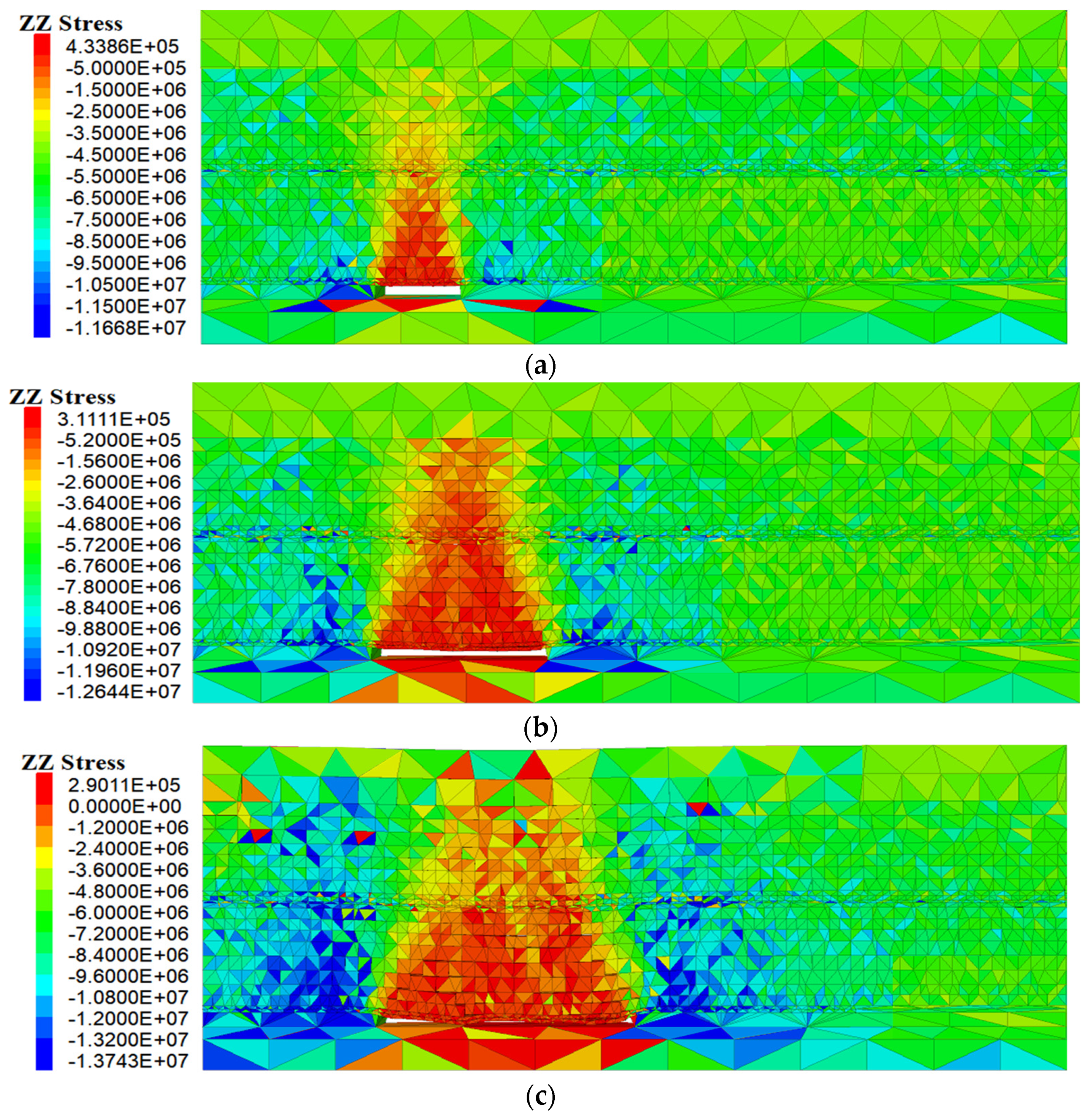
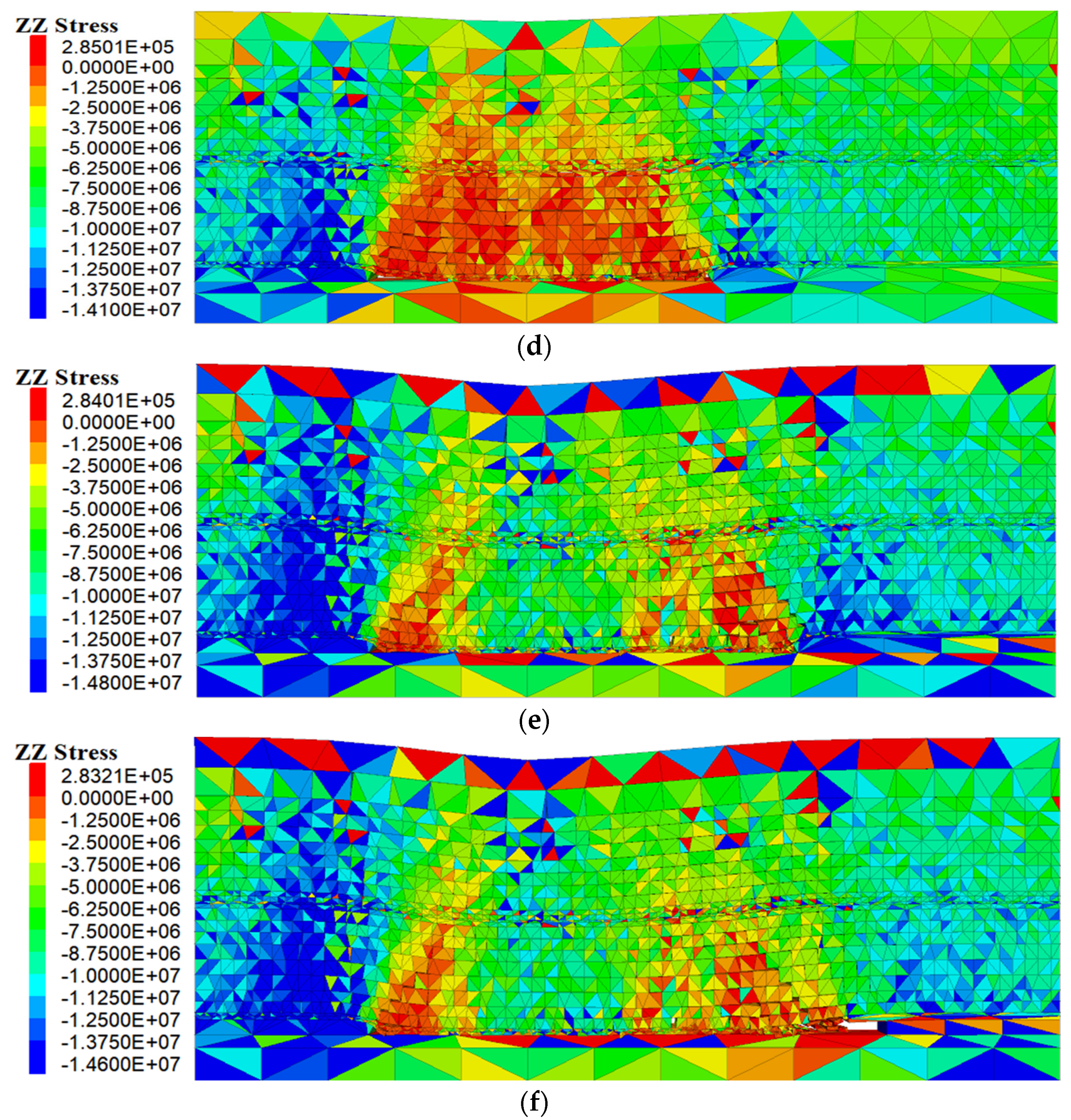
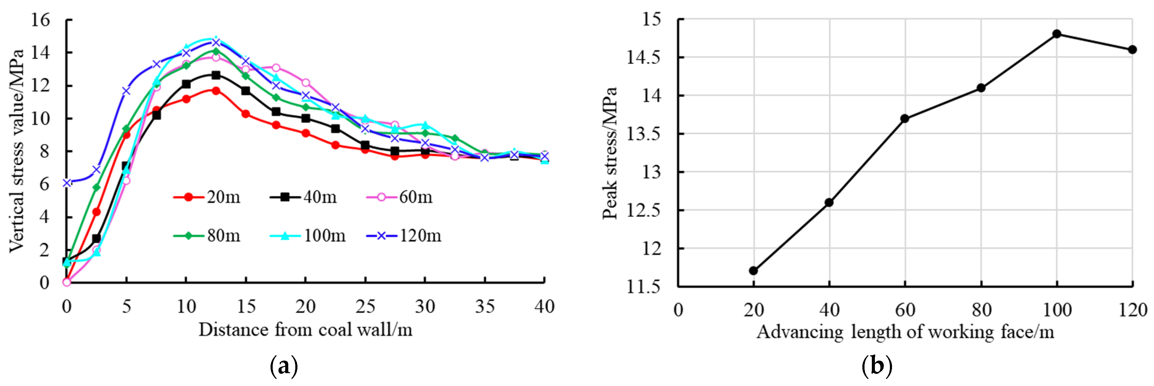
3.4. Distribution Characteristics of Stress Field in Working Face

The vertical stress distribution characteristics of the working face under different advancing lengths are shown in Figure 7. And vertical stress monitoring is carried out in the range of 40 m away from the coal wall in front of the working face, as shown in Figure 8. When the working face advances 20 m forward, the stress is released due to the separation crack of the roof above the goaf. However, there is a small degree of stress concentration at the coal pillar behind the working face and the coal wall in front. As the working face advances to 40 m, 60 m, or even 80 m, the stress peak position at the coal wall in front of it also moves forward. At the same time, the peak value of stress is increasing, and the range of stress-relaxation area is roughly consistent with the distribution range of cracks in the roof and overlying strata, and it is expanding. When the working face advances between 100 m and 120 m, the peak stress increases and remains basically stable. At this time, due to the large-scale destruction, subsidence, and compaction of the roof and overlying strata, the stress in the central goaf of the working face is stabilized again and transmitted downward. Therefore, the stress in the central part of the goaf increases relative to the primary rock stress and even produces a small degree of stress increase. This phenomenon is consistent with the distribution characteristics of roof and overlying strata cracks (opening-closing) in the working face. In addition, the monitoring results of the abutment pressure of the coal wall in front of the working face in Figure 8a are consistent with the theory in Figure 1b, indicating the reliability of the numerical simulation results. With the advance of the working face, the peak stress position in front of the working face is about 12.5 m away from the coal wall. The peak stress is about 1.56~1.97 times the primary rock stress.
Based on the numerical simulation study of the failure field and stress field of the working face, it can be seen that with the working face moving forward, the failure, cracks, and stress of the roof and overlying strata evolve synchronously, and their distribution ranges are basically the same. Especially when the working face reaches critical mining, the overall crack development height and stress peak value are basically stable. Among them, vertical cracks develop rapidly and penetrate through the goaf and overlying strata. At this time, the cracks in the middle of the goaf are gradually compacted and closed, and the stress is gradually increased. In this process, the crack experienced the state of “opening-closing”, and the stress experienced the state of “relaxation-concentration-stable”. Based on the above research, it lays the foundation for further exploring the influence of stress fields on gas distribution laws and directional borehole gas drainage technology in fractured zones.

4. Analysis of Coupling Effect between Stress Field and Gas Field

In order to further explore the coupling relationship between stress field and gas field and the influence of the law of stress field on gas pressure and permeability, 20 m deep on-site boreholes are constructed in the coal body of working face 9102 through tailgate and headgate, and four sets of survey lines are arranged. A borehole stress gauge, gas pressure gauge, and flowmeter are installed in the tailgate and headgate, respectively, and the distribution of abutment pressure, gas pressure, and gas seepage within 70 m from the coal wall of the working face is tested. Two sets of survey lines are arranged at the sides of the tailgate and headgate, respectively, and the distance between each set of survey lines is 10 m. There are 19 measuring points in each group of survey lines, and the distance between the monitoring points is 5 m. Among them, the monitoring points within 30 m of the coal wall are densely arranged with a spacing of 2.5 m. The site monitoring points on the working face are arranged as shown in Figure 9.
The on-site monitoring results of abutment pressure distribution, gas pressure distribution, and gas seepage in front of the working face are shown in Figure 10. The gas seepage and gas pressure in the working face 9102 are closely related to the stress distribution in the working face. The maximum peak stress of the coal body on the side of the tailgate can reach 17.9 MPa, which is about 15 m away from the coal wall of the working face. The area with a larger stress value is 7.5~22.5 m. The maximum peak stress of the coal body at the side of the headgate can reach 15.3 MPa, which is about 12.5 m away from the coal wall of the working face. The area with a larger stress value is 10~20 m. The peak stress and influence range of the coal body on the side of the tailgate are larger than those on the side of the headgate. The distribution trend of gas seepage in the advancing direction of the working face is basically consistent with the stress distribution, but the peak position is different. The maximum gas seepage value is generally within the range of 10~12.5 m from the working face. Affected by the goaf of the working face 9101, the maximum gas seepage of the coal body at the side of the headgate is about 1.9 m3/min, and that at the side of the tailgate is about 2.4 m3/min. The gas seepage from the coal body at the side of the tailgate is generally greater than that at the side of the headgate. The distribution law of gas pressure in the advancing direction of the working face is basically the same as that of stress, and the peak area of gas pressure is ahead of the peak area of stress. Affected by the goaf of the working face 9101, the maximum gas pressure of the coal body at the side of the headgate is about 0.55 MPa, and that at the side of the tailgate is about 0.25 MPa. The gas pressure of the coal body at the side of the tailgate is generally lower than that at the side of the headgate. In addition, compared with Figure 8a, the distribution trend of abutment pressure in front of the working face obtained by numerical simulation is basically consistent with the on-site measurement results, which can be compared and verified.
According to the above analysis, it can be known that stress disturbance is the main factor affecting gas seepage and gas pressure, and the changing trend of gas seepage and gas pressure is controlled by the stress change of the working face. With the increase in stress in the advancing direction of the working face, the gas pressure and gas seepage also increase. There is a positive correlation between gas fields and stress fields. Under the action of high stress near the working face, the pores and cracks of coal and rock mass further develop [18,31,32], providing a large space for gas to migrate. With the permeability of coal and rock mass increasing, the gas seepage increases, and the gas pressure decreases at this time. The peak position of gas pressure is the farthest from the coal wall, about 22.5~25 m, followed by the peak stress and the peak gas seepage. Influenced by the mining of the previous working face, the influence range of stress value and high stress of the coal body in the working face on the side of the tailgate is generally larger than that in the working face on the side of the headgate, and the gas pressure of the coal body in the working face on the side of the headgate is generally larger than that in the working face on the side of the tailgate, but the gas seepage is the opposite. The gas pressure, gas seepage, and permeability of coal seams are all controlled by the development and change of stress. For reasonable control of coal and rock gas dynamic disasters, the first condition is to control the gas pressure of the coal body and fully ensure the discharge of displaced gas.

5. Gas Migration Law and Drainage Engineering Test in Working Face

5.1. Gas Migration and Accumulation Law in Roof and Overlying Strata Failure Field

In order to further explore the gas accumulation and migration in the roof and overlying strata of the goaf, two groups of roof boreholes (d1, d2, d3, and d4) were respectively arranged in the tailgate and headgate of the working face in 1902 at a distance of 100 m from the coal wall, and the borehole inclination depth was 100 m. The included angle between each borehole and the working face in the horizontal direction is 70°. That is to say, along the axis direction of the mining roadway, it is inclined to the coal seam by 30°. In addition, the included angle between boreholes d1 and d3 and the strike direction of the coal seam is 20°, and the included angle between boreholes d2 and d4 and the strike direction of the coal seam is 45°. The specific borehole layout is shown in Figure 11. Firstly, monitoring the gas seepage of roof boreholes with different depths before coal mining and, secondly, monitoring the gas seepage of roof boreholes with different depths after coal mining.
The monitoring results for roof gas seepage are shown in Figure 12. Before the working face is mined to the borehole position, the trend of gas seepage in the roof and overlying strata is basically the same, and the gas seepage is small. With the increase in borehole depth, gas seepage decreases. This is because the roof and overlying strata are less disturbed, and the degree of crack development is low when the roadway is excavated in the working face. When the working face is mined to the borehole position, the gas seepage in each borehole is large. At the same time, there is a big difference between the gas seepage of roof boreholes before and after mining in the working face, and the gas seepage increases gradually with the increase in borehole depth in the fractured zone. This is because, under the influence of mining, the overlying strata cracks are highly developed, which provides favorable channels and spaces for gas migration and accumulation.
After mining in the working face, the larger gas seepage of boreholes d1 and d2 in the tailgate is 2.9~3.5 m3/min and 3.2~4.2 m3/min, respectively, and the larger gas seepage of boreholes d3 and d4 in the headgate is 1.8~2.1 m3/min and 2.1~2.9 m3/min, respectively. This shows that the gas seepage from the roof and overlying strata failure field on the side of the tailgate is greater than that on the side of the headgate. This is due to the influence of the return air flow in the working face, and there is gas accumulation in the roof and overlying strata of the tailgate side. According to the boreholes d1 and d3, the gas seepage is 1.8~3.5 m3/min and 0.9~2.1 m3/min, respectively, and the overall gas seepage is increasing. After conversion, the vertical height of the deepest part of the two groups of boreholes is 34 m, and the horizontal length goes deep into the goaf at 94 m (the vertical distance from the roadway wall is 47 m). Therefore, it can be known that the boreholes d1 and d3 are completely in the fractured zone of the goaf in the vertical direction. According to the boreholes d2 and d4, the gas seepage is 1~4.2 m3/min and 0.3~2.9 m3/min, respectively. With the increase in borehole depth, the gas seepage first increases, then stabilizes, and finally decreases. After conversion, the vertical height of the deepest part of the two groups of boreholes is 70.7 m, and the horizontal length is 70.7 m deep into the goaf (the vertical distance from the roadway wall is 35.35 m). However, the instantaneous reduction positions of gas seepage in boreholes d2 and d4 are at borehole depths of 90 m and 80 m, respectively, so it can be judged that cracks in the roof and overlying strata developed before this position. At the same time, there are still some cracks at the depths of 95 m and 85 m. The crack development degree is poor in the range of 95~100 m depth in borehole d2 and 85~100 m depth in borehole d4. Therefore, the corresponding vertical heights of boreholes d2 and d4 at this position are calculated to be 67.2 m and 60.1 m, respectively, which is the development height of the fractured zone, and the monitoring and judgment results are basically consistent with the numerical simulation results.
According to the gas seepage monitoring of the roof and overlying strata in the goaf in Figure 12, combined with the numerical simulation results of roof failure and overlying strata crack distribution (Figure 4 and Figure 5), the gas distribution law and migration path of the overlying strata fractured zone are analyzed along the working face advancing direction and the working face layout direction, respectively. According to the monitoring of gas seepage in the roof borehole, the roof was not disturbed and failed before coal mining, and the gas seepage was small. It can be considered that the gas distribution content of the roof above the solid coal body in the working face is extremely low, and the gas distribution is mainly the failed roof and overlying strata above the goaf in the working face. Under the influence of mining, the roof and overlying strata form separation layers and cracks, which provide a good channel and space for gas migration. As we all know, the density of gas is lower than that of air. When a large amount of gas accumulates in the stop, its pressure rises. There is a certain gas concentration and pressure difference in the crack channel of the rock stratum, so the gas will float upward along the crack in the vertical direction under the action of pneumatic power [33].
Along the advancing direction of the working face, the gas migration path in the fractured zone is shown in Figure 13. The gas is first released by the coal wall abutment pressure zone (I) in front of the working face and then mainly migrates to the roof and overlying strata above it along the crack channel of the roof separation zone (II). Among them, when the gas migrates to the large separation layer or dislocation space of the rock stratum, it will form a certain degree of accumulation phenomenon here. At the same time, the gas will also migrate to the recompression zone (III) behind the working face in the horizontal direction, but the gas migration degree is relatively small because of the recompression of the cracks in the goaf. Finally, the gas forms a stable accumulation at the highest positions A and B in the fractured zone, and the gas content is huge. However, as the working face moves forward, the coal wall abutment pressure zone (I), the roof separation zone (II), and the recompression zone (III) move forward continuously, so the main gas accumulation positions A and B are also moving forward. At the same time, it is clear that with the mining of the working face and the accumulation of time, the gas content at position A will be higher than that at position B.
Along the layout direction of the working face, the distribution of cracks in the roof and overlying strata is shown in Figure 14. The overall development height of the cracks is about 61 m, and the cracks are mainly developed in horizontal separation. Basically, the upward penetration in the inclined direction is realized. Combined with the coal seam gas seepage and roof gas seepage monitored from the tailgate and the headgate in Figure 10 and Figure 12, the gas migration path in the fractured zone is analyzed as shown in Figure 15. The gas is first released from the coal wall abutment pressure zone (I) in front of the working face, diffused along the tailgate and the headgate of the working face, and then migrated from the crack channel of the goaf to the roof and overlying strata above it. Among them, when the gas migrates to the large separation layer or dislocation space of the rock stratum, it will form a certain degree of accumulation. Finally, the gas forms a stable accumulation at the highest positions C and D in the fractured zone, and the gas content is huge. Among them, position C is the upper corner of the working face, and the gas content at this position is higher than that at position D.

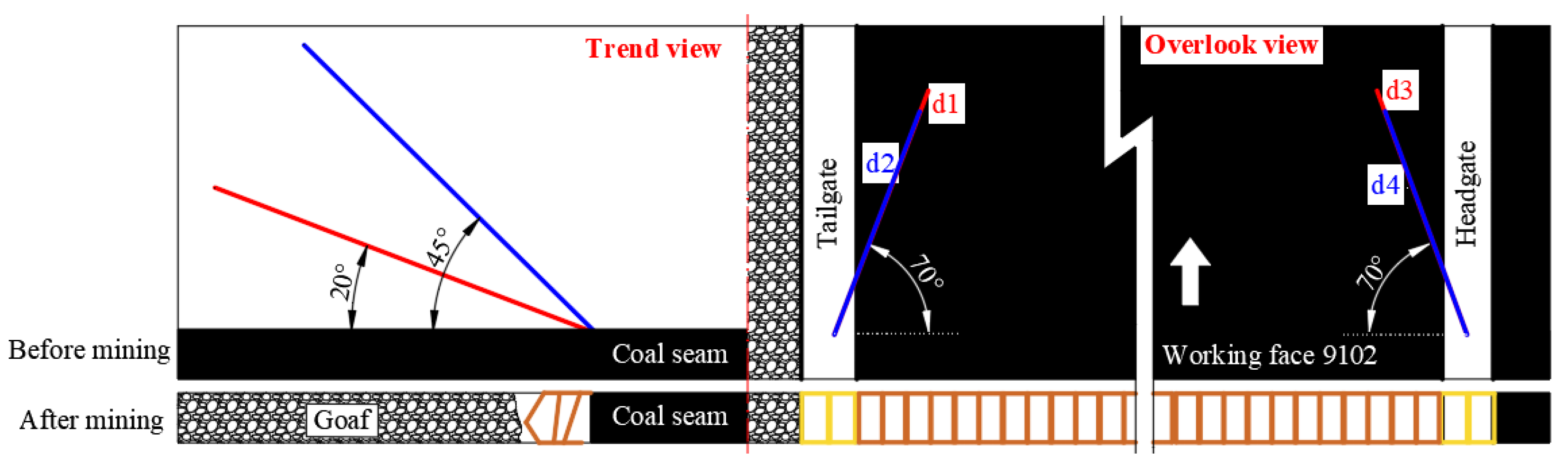
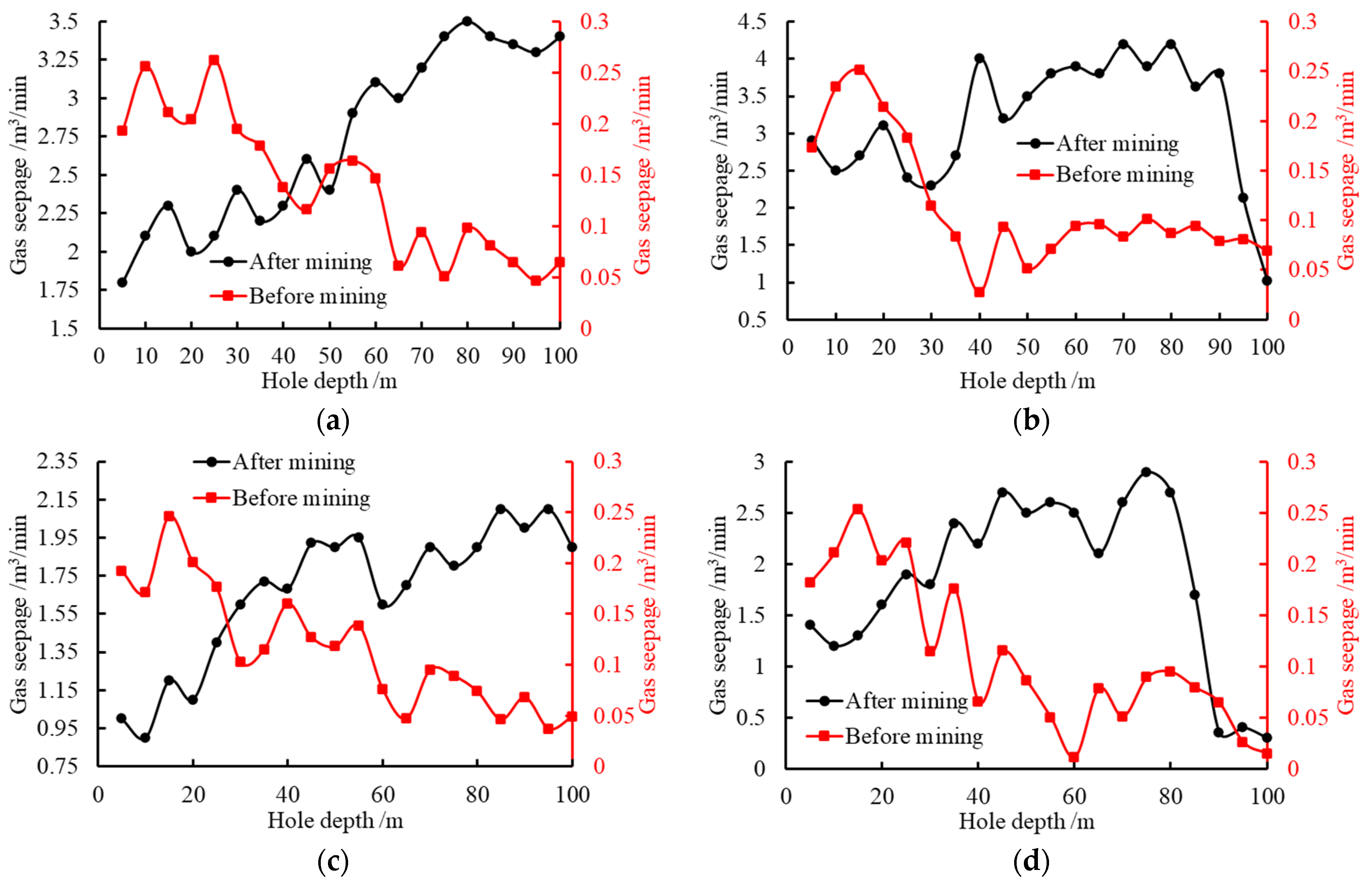
5.2. Test Study on Gas Drainage Technology by Directional Borehole in Fractured Zone

Based on the analysis of the law of gas accumulation and migration in the roof and overlying strata fractured zone, firstly, the development height of the fractured zone can reach 60~67.2 m, and secondly, the gas distribution and accumulation are mainly in the roof and overlying strata crack on the tailgate side. In this paper, aiming at working face 9102, not mined coal seam, gas drainage boreholes with a depth of 150 m are arranged at positions about 30 m and 45 m away from the vertical height of coal seam from the coal body side of the tailgate and headgate, respectively, as on-site tests. The direction of boreholes points to the back of the working face, and the designed dip angle of each borehole is about 30°. The specific arrangement scheme is shown in Figure 16.
According to the gas drainage boreholes arranged in Figure 16, the relationship between gas drainage volume and time is obtained, as shown in Figure 17. As the working face moves forward, the gas drainage amount of borehole T1 shows a decreasing trend as a whole. At the same time, before the working face advances 25 m, the gas drainage amount of borehole T1 is the largest. This phenomenon is due to the fact that the borehole T1 is close to the goaf of the previous working face, and the gas extracted at this position includes not only the working face but also the goaf of the previous working face. Moreover, due to the undeveloped cracks in the borehole T1, the gas extracted is mainly from the goaf of the previous working face. The gas drainage boreholes T2, T3, T4, H1, H2, and H3 are advancing with the working face, and the overall gas drainage volume shows a trend of increasing first and then decreasing. It shows that each borehole is affected by periodic roof caving, and the variation law of rock cracks near the borehole is that the primary cracks develop first and the secondary cracks are derived in large quantities. These cracks gradually penetrated to form a gas flow channel, and then some cracks were closed due to the influence of mining, which reduced the gas drainage amount in the borehole. Among them, the crack closure has the greatest influence on the gas drainage quantity of boreholes T2, T3, and H1. In addition, the gas drainage amount of boreholes T2, T3, and T4 on the tailgate side is larger in turn, and the gas drainage amount of boreholes H1, H2, and H3 on the headgate side is larger in turn. At the same time, the gas drainage amount at the side of the tailgate is greater than that at the side of the headgate. This phenomenon is basically consistent with the law of gas migration and distribution in fractured zones.
In order to evaluate the effect of gas drainage by boreholes in fractured zones, the gas concentration in the upper corner and tailgate during the process of the working face advancing 150 m when gas drainage is carried out in fractured zones and no gas drainage is compared, as shown in Figure 18. When gas drainage boreholes are not arranged in the fractured zone, the larger gas concentrations in the upper corner and tailgate are about 0.35~0.5% and 0.3~0.4%, respectively. There is obvious gas accumulation in the upper corner. When the gas drainage boreholes as shown in Figure 16 are arranged, the gas concentrations in the upper corner and tailgate are about 0.14~0.32% and 0.19~0.28% respectively, and the gas concentrations are reduced by 30~36%. After gas drainage by borehole in the fractured zone, the gas concentration is low and the drainage effect is remarkable. Thus, it shows that the directional borehole in the fractured zone is reasonable, which can effectively reduce the gas concentration in the upper corner of the working face and the tailgate and provide a guarantee for safe mining in the mine.

6. Conclusions

Through the combination of 3DEC numerical simulation and on-site monitoring, the distribution characteristics of stress field, fracture field, gas pressure, and gas seepage in the working face are deeply explored; the coupling effect of stress field and gas field in the working face and its influence on gas migration and distribution are revealed; and effective gas drainage technology in the fracture zone is put forward. The main conclusions are as follows:
(1)
With the working face advancing forward, the roof cracks experienced the process of “opening-closing”, and the stress experienced the process of “relaxation-concentration-stable”. When the height of crack development and the peak stress of the roof of the working face reach a stable state, the height of crack development is about 60~67.2 m and the peak stress is about 1.56~1.97 times the original rock stress.
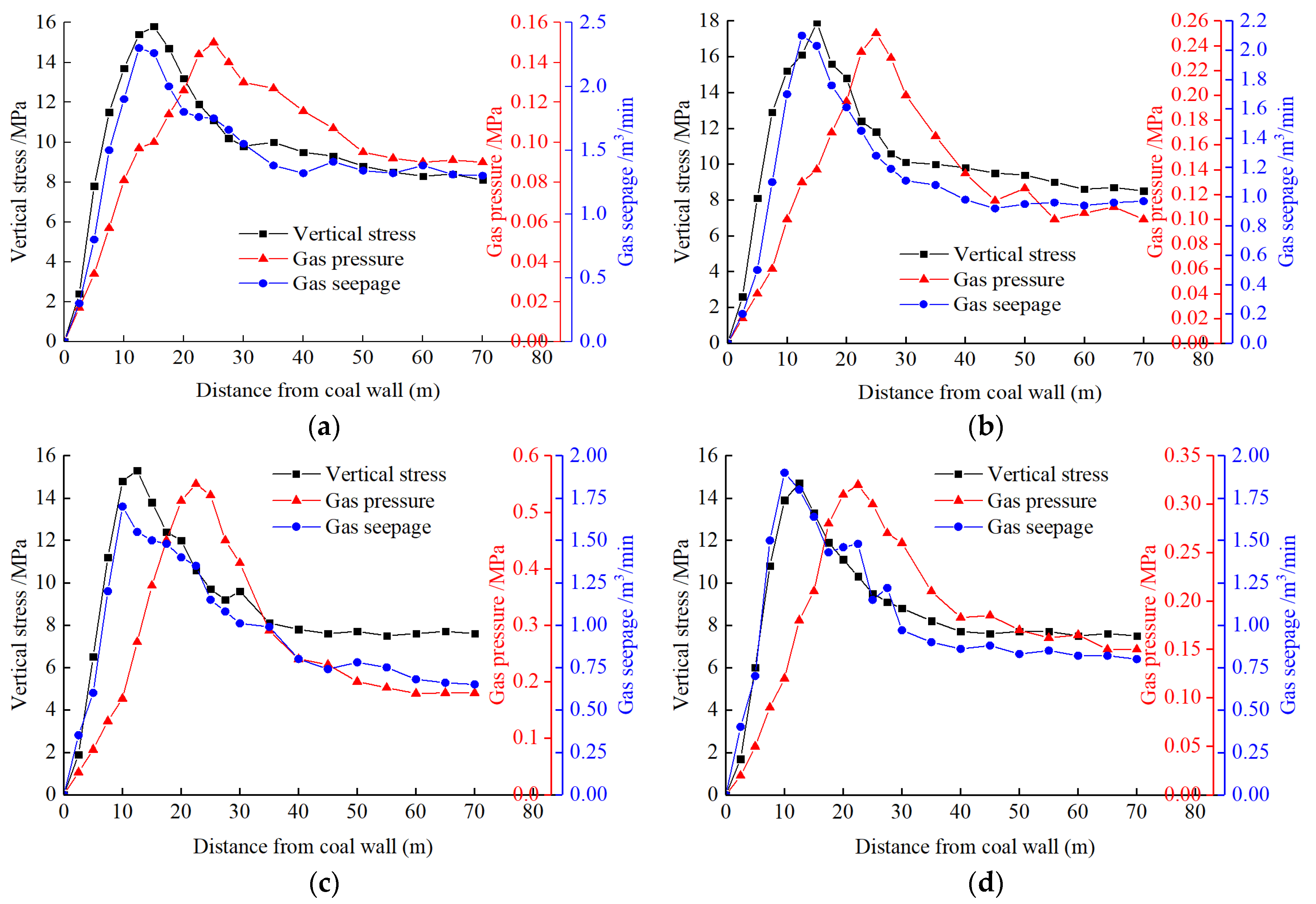
(2)
The changing trend of gas seepage and gas pressure is controlled by the stress change of the working face, which has a typical coupling effect. With the increase in stress in the advancing direction of the working face, the gas pressure and gas seepage also increase. The peak position of gas pressure is the farthest from the coal wall (22.5~25 m) ahead of the working face, followed by the peak of stress (12.5~15 m) and the peak of gas seepage (10~12.5 m).
(3)
There is a certain correlation between coal seam permeability and gas seepage. Under the action of high stress near the working face, the pores and cracks in the coal and rock mass further develop. The permeability of coal and rock mass increases, the gas seepage increases, and the gas pressure decreases at this time.
(4)
The stress value and the influence range of high stress on the coal body in the working face on the tailgate side are generally larger than those in the working face on the headgate side, but the gas pressure is opposite. Generally, the gas seepage of the coal body in the working face and the fractured zone above the tailgate side is higher than that on the headgate side.
(5)
Mining cracks and strata separation spaces provide a good channel and space for gas migration and accumulation. Along the advancing direction of the working face, the gas is mainly concentrated in the crack space above the roof separation zone, and the accumulation position moves forward. Along the layout direction of the working face, there is gas accumulation in the roof of the tailgate side and the crack space of overlying strata.
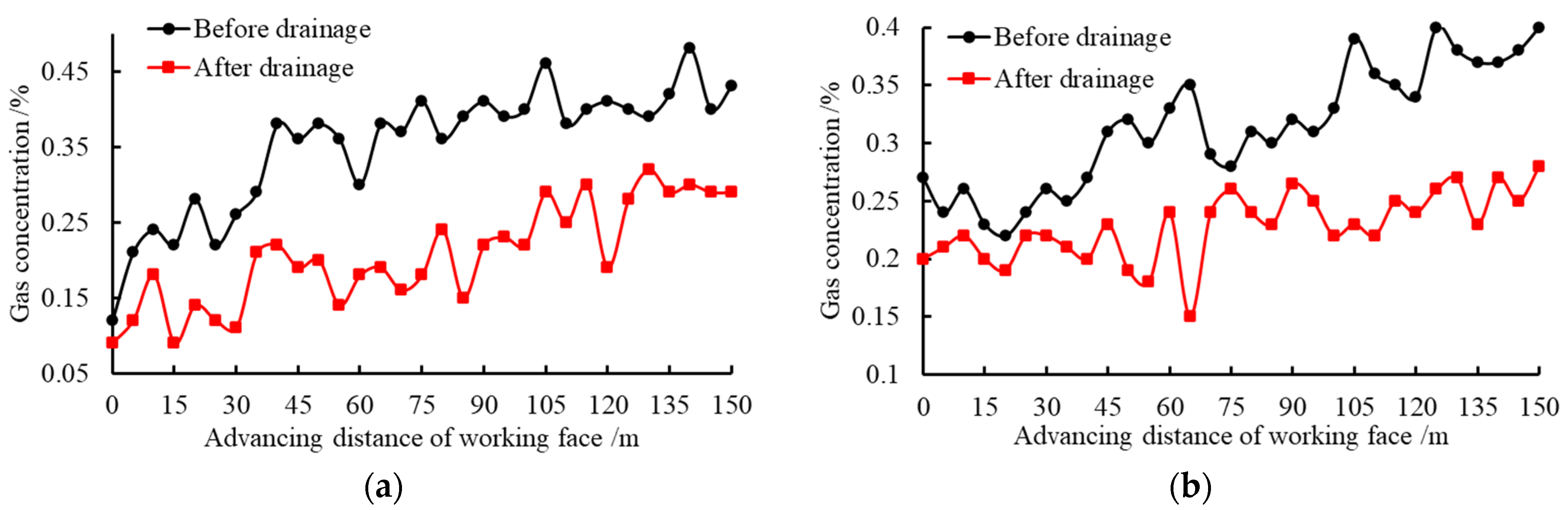
(6)
Based on the law of gas migration and distribution, the gas drainage technology of directional boreholes in fractured zones is put forward. The overall gas drainage effect is remarkable, which effectively reduces the gas concentration of 30~36% in the upper corner of the working face and the tailgate.

Author Contributions

S.L.: Formal analysis, software, data curation, writing—original draft preparation. Z.W.: Conceptualization, methodology, resources, writing—review and editing. All authors have read and agreed to the published version of the manuscript.

Funding

This research received no external funding.

Data Availability Statement

Not applicable.

Conflicts of Interest

The authors declare no conflict of interest.

References

  1. Jia, Z.; Ye, Q.; Li, H. Damage Assessment of Roadway Wall Caused by Dynamic and Static Load Action of Gas Explosion. Processes 2023, 11, 580. [Google Scholar] [CrossRef]
  2. Waloski, R.; Korzeniowski, W.; Bołoz, Ł.; Rączka, W. Identification of Rock Mass Critical Discontinuities While Borehole Drilling. Energies 2021, 14, 2748. [Google Scholar] [CrossRef]
  3. Shu, L.Y.; Wang, K.; Liu, Z.S.; Zhao, W.; Zhu, N.N.; Lei, Y. A novel physical model of coal and gas outbursts mechanism: Insights into the process and initiation criterion of outbursts. Fuel 2022, 323, 124305. [Google Scholar] [CrossRef]
  4. Petkovic, M.; Chen, Y.; Gamrath, I.; Gotzes, U.; Hadjidimitrou, N.S.; Zittel, J.; Xu, X.F.; Koch, T. A hybrid approach for high precision prediction of gas flows. Energy Syst. 2021, 13, 1–26. [Google Scholar] [CrossRef]
  5. Lei, Y.; Cheng, Y.P.; Wang, L.; Ren, T.; Li, Q.Y. Potential infrasonic tremors in coal seam systems: Implications for the prediction of coal and gas outbursts. Fuel 2022, 326, 125000. [Google Scholar] [CrossRef]
  6. Ziętek, B.; Banasiewicz, A.; Zimroz, R.; Szrek, J.; Gola, S. A Portable Environmental Data-Monitoring System for Air Hazard Evaluation in Deep Underground Mines. Energies 2020, 13, 6331. [Google Scholar] [CrossRef]
  7. Cheng, L.; Ge, Z.; Chen, J.; Ding, H.; Zou, L.; Li, K. A Sequential Approach for Integrated Coal and Gas Mining of Closely-Spaced Outburst Coal Seams: Results from a Case Study Including Mine Safety Improvements and Greenhouse Gas Reductions. Energies 2018, 11, 3023. [Google Scholar] [CrossRef]
  8. Lalik, K.; Dominik, I.; Skrzypkowski, K.; Korzeniowski, W.; Zagórski, K. Self-Excited Acoustical Measurement System for Rock Mass Stress Mapping. Sensors 2021, 21, 6749. [Google Scholar] [CrossRef] [PubMed]
  9. Szlązak, N.; Swolkień, J.; Kamiński, P. Design of Coal Seam Exploitation in Methane Hazard Conditions: A Case Study. Energies 2023, 16, 365. [Google Scholar] [CrossRef]
  10. Xiong, Y.; Kong, D.Z.; Wen, Z.J.; Wu, G.Y.; Liu, Q.Z. Analysis of coal face stability of lower coal seam under repeated mining in close coal seams group. Sci. Rep. 2022, 12, 509. [Google Scholar] [CrossRef]
  11. Li, X.B.; Ji, D.L.; Han, P.H.; Li, Q.S.; Zhao, H.B.; He, F.L. Study of water-conducting fractured zone development law and assessment method in longwall mining of shallow coal seam. Sci. Rep. 2022, 12, 7994. [Google Scholar] [CrossRef] [PubMed]
  12. Zhang, F.; Zhang, J. Research on Joint Protection Layers and Gas Prevention Technology in Outburst Coal Seams. Sustainability 2022, 14, 8859. [Google Scholar] [CrossRef]
  13. Wang, G.; Fan, C.; Xu, H.; Liu, X.; Wang, R. Determination of Long Horizontal Borehole Height in Roofs and Its Application to Gas Drainage. Energies 2018, 11, 2647. [Google Scholar] [CrossRef]
  14. Qian, M.G.; Xu, J.L. Study on the “O–SHAPE” circle distribution characteristics of mining-induced fractures in the overlaying strata. J. China Coal Soc. 1998, 23, 20–23. [Google Scholar]
  15. Li, S.G.; Lin, H.F.; Zhao, P.X.; Xiao, P.; Pan, H.Y. Mining fissure elliptic paraboloid zone and dynamic evolution of coal and methane mining. J. China Coal Soc. 2014, 39, 1455–1462. [Google Scholar]
  16. Lin, H.F.; Li, S.G.; Cheng, L.H.; Wang, H.S. Experimental analysis of dynamic evolution model of fracture zone caused by overburden mining. J. Min. Saf. Eng. 2011, 28, 298–303. [Google Scholar]
  17. Lin, H.F.; Wang, X.; Xu, P.Y.; Kong, X.G.; Shuang, H.Q.; Zhao, P.X. Evolution characteristics analysis and engineering application of pressure-relieved gas reservoir in extra-thick coal seam mining. Coal Sci. Technol. 2023, 51, 173–182. [Google Scholar] [CrossRef]
  18. Xu, X.; Kong, D.Z.; Xiong, Y.; Chen, F. Evolution Regularity and Control Technology of Coal Face Rupture Induced by the movement of Overlying Strata Under the Influence of Mining. Min. Metall. Explor. 2023, 40, 435–452. [Google Scholar] [CrossRef]
  19. Wang, G.; Wu, M.M.; Wang, R.; Xu, H.; Song, X. Height of the mining-induced fractured zone above a coal face. Eng. Geol. 2017, 216, 140–152. [Google Scholar] [CrossRef]
  20. Li, L.; Wu, G.; Liu, Q. Study on Overburden Movement and Fissure Evolution Law of Protective Layer Mining in Shallow Coal Seam. Energies 2022, 15, 1831. [Google Scholar] [CrossRef]
  21. Zhao, Y.; Lin, B.Q.; Liu, T.; Zheng, Y.N.; Kong, J.; Li, Q.Z.; Song, H.R. Mechanism of multifield coupling-induced outburst in mining-disturbed coal seam. Fuel 2020, 272, 117716. [Google Scholar] [CrossRef]
  22. Zhang, B.C.; Liang, Y.P.; Sun, H.T.; Wang, K.Q.; Zou, Q.L.; Dai, J.H. Evolution of mining-induced fractured zone height above a mined panel in longwall coal mining. Arab. J. Geosci. 2022, 15, 6. [Google Scholar] [CrossRef]
  23. Zhang, F.; Wang, G.; Wang, B. Study and Application of High-Level Directional Extraction Borehole Based on Mining Fracture Evolution Law of Overburden Strata. Sustainability 2023, 15, 2806. [Google Scholar] [CrossRef]
  24. Nian, F.; Ju, F.; Zheng, C.; Wu, H.; Cheng, X. Effects of Coal Permeability Anisotropy on Gas Extraction Performance. Processes 2023, 11, 1408. [Google Scholar] [CrossRef]
  25. Zhang, C.L.; Xu, J.; Peng, S.J.; Li, Q.X.; Yan, F.Z.; Chen, Y.X. Dynamic behavior of gas pressure and optimization of borehole length in stress relaxation zone during coalbed methane production. Fuel 2018, 233, 816–824. [Google Scholar] [CrossRef]
  26. Zhang, D.Y.; Zhang, M.B.; Wang, L.K.; Zeng, R.P.; Wang, J.B. Determination and Application of Reasonable Levels for Highly Directional Long Boreholes in Deep Outburst Coal Seams. Geofluids 2022, 2022, 3621921. [Google Scholar] [CrossRef]
  27. Liu, C.F.; Zhang, L.; Li, Y.C.; Liu, F.G.; Martyushev, D.A.; Yang, Y.F. Effects of microfractures on permeability in carbonate rocks based on digital core technology. Adv. Geo-Energy Res. 2022, 6, 86–90. [Google Scholar] [CrossRef]
  28. Dzhioeva, A.K.; Brigida, V.S. Spatial non-linearity of methane release dynamics in underground boreholes for sustainable mining. J. Min. Inst. 2020, 245, 522–530. [Google Scholar] [CrossRef]
  29. Zhang, P.S.; Sun, B.Y. Distribution characteristics of the advance abutment pressure in a deep stope. J. Geophys. Eng. 2020, 17, 686–699. [Google Scholar] [CrossRef]
  30. Xie, J.L.; Xu, J.L.; Wang, F. Mining-induced stress distribution of the working face in a kilometer-deep coal mine—A case study in Tangshan coal mine. J. Geophys. Eng. 2018, 15, 2060–2070. [Google Scholar] [CrossRef]
  31. Xiong, Y.; Yang, S.L.; Kong, D.Z.; Song, G.F.; Ma, Z.Q.; Zuo, Y.J. Analysis on early warning of coal sample failure based on crack development law and strain evolution characteristics. Eng. Fail. Anal. 2023, 148, 107170. [Google Scholar] [CrossRef]
  32. Izadi, G.; Wang, S.G.; Elsworth, D.; Liu, J.S.; Wu, Y.; Pone, D. Permeability evolution of fluid-infiltrated coal containing discrete fractures. Int. J. Coal Geol. 2010, 85, 202–211. [Google Scholar] [CrossRef]
  33. Li, Z.; Wang, L.; Ding, K.; Ren, B.; Wang, S.; Jiang, C.; Pan, Z. Study on Fracture and Seepage Evolution Law of Stope Covered by Thin Bedrock under Mining Influence. Minerals 2022, 12, 375. [Google Scholar] [CrossRef]
Figure 1. Schematic diagram of the abutment pressure of the working face (a) transverse three-zone, (b) abutment pressure.
Energies 16 06672 g001
Figure 2. Coal seam histogram of working face.
Energies 16 06672 g002
Figure 3. Numerical model.
Energies 16 06672 g003
Figure 4. Failure characteristics of roof and overlying strata, (a) Advance 20 m, (b) Advance 40 m, (c) Advance 60 m, (d) Advance 80 m, (e) Advance 100 m, (f) Advance 120 m.
Energies 16 06672 g004aEnergies 16 06672 g004b
Figure 5. Development of cracks in the roof and overlying strata, (a) Advance 20 m, (b) Advance 40 m, (c) Advance 60 m, (d) Advance 80 m, (e) Advance 100 m, (f) Advance 120 m.
Energies 16 06672 g005
Figure 6. Statistics of crack development under different advancing lengths in the working face: (a) Cracks development height; (b) Number of vertical cracks.
Energies 16 06672 g006
Figure 7. Vertical stress distribution characteristics of the working face, (a) Advance 20 m, (b) Advance 40 m, (c) Advance 60 m, (d) Advance 80 m, (e) Advance 100 m, (f) Advance 120 m.
Energies 16 06672 g007aEnergies 16 06672 g007b
Figure 8. Evolution characteristics of vertical stress in front of the working face: (a) Vertical stress curve; (b) Peak stress.
Energies 16 06672 g008
Figure 9. Schematic diagram of measuring points in coal body of working face.
Energies 16 06672 g009
Figure 10. Variation curve of working face stress and gas pressure and seepage, (a) Monitoring line ① (b) Monitoring line ②, (c) Monitoring line ③ (d) Monitoring line ④.
Energies 16 06672 g010
Figure 11. Schematic diagram of roof boreholes layout.
Energies 16 06672 g011
Figure 12. Gas seepage of roof and overlying strata, (a) Borehole d1, (b) Borehole d2, (c) Borehole d3, (d) Borehole d4.
Energies 16 06672 g012
Figure 13. Gas migration path in front of working face.
Energies 16 06672 g013
Figure 14. Cracks distribution characteristics of the roof and overlying strata in the layout direction of working face.
Energies 16 06672 g014
Figure 15. Gas migration path in layout direction of working face.
Energies 16 06672 g015
Figure 16. Schematic layout of the test boreholes.
Energies 16 06672 g016
Figure 17. Gas drainage from boreholes in fractured zones: (a) Borehole on the side of the tailgate; (b) Borehole on the side of the headgate.
Energies 16 06672 g017
Figure 18. Comparison of concentration before and after gas drainage, (a) Upper corner, (b) Tailgate.
Energies 16 06672 g018
Table 1. Physical and mechanical parameters of coal and rock mass.
LithologyUnit Weight kN/m3Average Thickness/mElastic Modulus/GPaPoisson RatioCohesion/MPaInternal Friction Angle/°Tensile Strength/MPa
Fine sandstone2.5414.6180.295.2397.2
Argillaceous siltstone2.510.8160.154.6366.2
Siltstone2.4612.516.60.175.538.77.15
Mudstone2.372.615.60.182.2407.05
Muddy sandstone2.320.67.350.162.9926.21.1
Mudstone2.351.2160.172.2251.5
Siltstone2.448.818.60.173.5322.8
Fine sandstone2.5411.4180.295.2397.2
Siltstone2.445.618.60.173.5322.8
Mudstone2.11.8130.212.2353.15
9# coal seam1.353.81.70.321.8200.8
Mudstone2.13.24130.212.1353.18
Fine sandstone2.548.8180.295.2342.2
Table 2. Joint mechanical parameters of coal and rock mass.
LithologyElastic Modulus/GPaNormal Stiffness/GPaTangential Stiffness/GPa
Fine sandstone2.344.73.6
Argillaceous siltstone1.623.222.39
Siltstone1.543.012.28
Mudstone1.072.411.96
Muddy sandstone1.262.522.1
Mudstone1.072.411.96
Siltstone1.543.012.28
Fine sandstone2.344.73.6
Siltstone1.543.012.28
Mudstone1.072.411.96
9# coal seam0.331.251.02
Mudstone1.072.411.96
Fine sandstone2.344.73.6
Disclaimer/Publisher’s Note: The statements, opinions and data contained in all publications are solely those of the individual author(s) and contributor(s) and not of MDPI and/or the editor(s). MDPI and/or the editor(s) disclaim responsibility for any injury to people or property resulting from any ideas, methods, instructions or products referred to in the content.

