1. Introduction
The research and design of modern electrical machine structures is the basis for the development of many industries. Increasing the efficiency and power density of electric machines makes it possible to reduce electricity consumption and, thus, contribute to reducing carbon footprint. Efficient electric drive units for electric vehicles will make it possible to increase the range of vehicles or reduce the size of their energy storage. Currently, advanced research is being carried out on designs that combine several basic types of electric machines to maximize their benefits. An important example of such a design is the HE-PMa-SynRM (Hybrid Excited Permanent Magnet assisted Synchronous Reluctance Machine), which combines features of PMSMs (Permanent Magnet Synchronous Machine), WFSMs (Wound Field Synchronous Machine), SynRMs (Synchronous Reluctance Machine), and uses permanent magnet flux control methods.
The aim of this paper is to use the advantages of various electric machines with permanent magnets, reluctance machines, and machines that combine the two to create a an innovative HEPMa-SynRM machine, as well as thoroughly analyze and optimize it, and examine the impact of the stator skew on its performance.
For this purpose, the following chapters present a brief description of the innovative designs of electric machines with permanent magnets and reluctance machines, which were the starting point for the development of the proposed HEPMa-SynRM machine. These chapters are a review of the selected solutions for modern electrical machines and the partial solutions which were the basis for designing the proposed machine.
3. Overview of Selected Solutions for Permanent Magnet Synchronous Machines, Synchronous Reluctance Machines and Permanent Magnet Assisted Synchronous Reluctance Machines
The Permanent Magnet Synchronous Machine is a modification of the classic synchronous machine design, in which the powered rotor windings are replaced by permanent magnets. This modification makes it possible to achieve higher power densities and avoids the need to supply the machine’s rotor.
Paper [
1] presents a very interesting Permanent Magnet Synchronous Motor with toroidal winding design intended for use in electric vehicles. The simulation studies carried out indicate numerous advantages over the traditional PMSM and toroid winding PMSM designs in terms of reduced losses in the machine’s magnetic circuit, gaining free space that can improve the thermal properties of the machine and increasing the value of the torque produced. Disadvantages of the design used include the large amount of heat generated in the machine windings.
The authors of paper [
2] presented a multiphase PMSM with an asymmetric winding motor for use as a single propulsion unit for an electric aircraft (
Figure 2). Three independent sets of windings, with different number of windings and current ratings, have been placed in the stator slots of the machine. Each allows the same torque value and a different speed value to be achieved. The authors developed a stochastic algorithm to control and supply the machine windings to optimize the efficiency of the machine. Based on the FEM calculations, better low-speed and low-load performances were achieved compared to a classic radial flux PMSM motor design with similar parameters—i.e., peak power decreased, while efficiency improved for high speeds. The proposed design allows for increased machine reliability by reducing the temperatures reached, which is particularly important in the aviation industry.
In article [
3], the authors undertook a comparative analysis of a 3-phase and a 5-phase PMSM motor for use as an electric vehicle drive. Simulation studies showed that the 5-phase design had a higher efficiency value and a significantly lower cogging torque value. Based on thermal analysis, the power loss and rotor temperature were also found to be lower for the 5-phase PMSM design. The slot structure has a similar design to the structure presented in
Figure 1.
The authors of paper [
4] (
Figure 3) have studied a prototype fractional slot PMSM motor with a high power to weight ratio. They focused on optimizing the slot-pole structure to maximize the achieved power density and minimize the losses in the rotor, as well as selecting the optimum number of pole pairs. A FEM simulation study was carried out, the results of which were compared with experimental studies of a prototype 20 poles and 24 slots design. The analysis revealed that a design with 24 poles and 27 slots appears to be the optimal in terms of power density ratio, but requires a 960 Hz power supply, making it very difficult to apply. Optimization to minimize power losses in the rotor identified the 20p-30s design (for number of slots per pole and phase
q = 0.5) as the most optimal, which achieves approximately 2.6 times lower losses than the 24p-27s design.
Article [
5] presents a hybrid propulsion system based on an Emrax 228 PMSM engine with a maximum continuous power of 50 kW and a Rotax 912 ULS internal combustion engine. A simulated power supply for the electric motor from a lithium battery bank with a nominal voltage of 74 V and a capacity of 3 kWh was modelled, and simulation and experimental tests were carried out to reflect the in-flight behavior of the system. A high degree of convergence between the experimental and simulation results obtained (<8% discrepancy) was confirmed by tests. In the paper presented here, a similar method of flux weakening was also used by reducing the energy storage voltage.
Article [
6] presents the prototype design of a high-speed synchronous reluctance motor with an axially laminated anisotropic rotor ALASynRM. The proposed prototype features a power rating of 12 kW and a rated rotational speed of 24,000 rpm. The machine’s rotor is constructed of alternating thin magnetic and non-magnetic layers bonded together by a lamination process. The proposed design provides high mechanical durability at high speeds and high temperature resistance. It has been shown that this design has an efficiency over 3% higher than the IM with the smooth solid rotor and 0.25% higher than the IM with the slitted rotor. At the same time, the prototype achieves a significantly higher torque ripple of 43.1% of the rated torque.
Article [
7] presents the design of a model of a 4-pole Syn RM motor with a power output of 500 W, a rotational speed of 1500 rpm and a rated torque of 3 Nm, produced using 3D printing. Comparing it with a similar motor currently used in industry to power a fan, an increase of approximately 5.8% in output power and 0.6% in efficiency was obtained in FEM tests. A major limitation of Syn RM machines manufactured via 3D printing is mechanical and thermal durability. The design proposed in this paper uses a similar shape for the magnetic barriers and also assumes an equal width. Compared to the design proposed by the authors, a higher number of air barriers per pole (5 vs. 3) and a lower number of poles (4 vs. 6) were used.
The authors of paper [
8] presented a procedure for selecting the optimum value of the magnetic barriers, widths, and angles of a SynRM machine to achieve high average torque values and low torque ripple. They compared their method of parameterized equations with the three currently used methods and obtained a higher average value of the achieved electromagnetic torque with lower pulsations for the tested design.
Article [
9] presents the process of designing the rotor of a SynRM machine based on the stator of a four-pole three-phase induction machine with a power output of 11 kW and a rated speed of 1440 rpm for use as a variable-speed pump or fan drive. The authors designed the dimensions of the air barriers to obtain a high value of the inductance difference in the
d- and
q-axis of the machine’s electromagnetic circuit, thereby maximizing the electromagnetic torque value achieved. They analyzed the torque ripple values and the achieved efficiency depending on the number of barrier layers, as well as the influence of the material, on the efficiency and power factor of the machine. On this basis, they determined the optimal rotor parameters for five magnetic barriers per machine pole and the machine material factor.
The authors of paper [
10] presented an optimization of the SynRM design which maximized torque and power factor values. On the basis of the optimization procedure adopted, the parameters of the air barriers (their number per pole, the position of their location and the distance between the individual barriers), the size of the air gap, and the average flux density in the area between the barriers were determined. The optimum design in relation to the worst-case result according to the Taguchi methodology is characterized by higher efficiency, higher power factor, and higher torque.
Paper [
10] presents an optimization process for an actuator based on the Axially Laminated Synchronous Reluctance Machine (ALA-SynRM) to maximize the torque density. The optimization process was performed using the Box–Behnken method and allowed the following optimal values to be selected:
Open slot—specifying the opening dimensions of the stator slots,
Position—determining the size of the rotor and thus the size of the air gap,
Core thickness—determining the width of the rotor core between the magnetic barriers,
Insulator thickness—determining the width of magnetic barriers.
The experimental tests carried out overlapped to a large extent with the simulation results, thus confirming the validity of the simulation model and machine prototype created. In conclusion, it is indicated that the tested design, due to its higher power density and higher efficiency per unit, can very successfully replace the currently used induction motors in actuators.
Synchronous Reluctance machines are being extensively developed by scientists around the world. Some important designs are presented in papers [
11,
12,
13,
14,
15,
16]. In order to achieve higher machine torque values and to further increase the power density, the SynRM machine design was successively modified by adding magnetic field sources (permanent magnets) in the rotor.
The authors of paper [
17] presented the design of a 4-pole, 24-slot modular permanent magnet-assisted synchronous reluctance motor. The rotor was divided into three sections operating on a single shaft, two outer sections of IPM design and a central PMa-SynRM section. An evolution algorithm was used to optimize the machine. Based on simulation and experimental studies, it has been shown that the proposed solution is characterized by a low torque ripple, high power factor, and low iron losses due to eddy currents.
The authors in paper [
18] carried out a comparative analysis of six different rotor designs of the PMaSynRM machine to maximize motor performance and minimize the use of permanent magnets. Analyses were carried out in terms of the inductance values achieved, the torque produced, the demagnetization of the permanent magnets used, and the torque and power vs. speed characteristics. Based on these, a positive effect of the arrangement of the permanent magnets along the
q-axis, or in barriers on the value of the induced electromagnetic torque, was noted. It was also indicated that for designs with a small number of permanent magnets used, it is optimal to place them along the
d-axis of the machine.
Article [
19] presents the design of the core skew machine considering the manufacturability of double-layer spoke-type PMSM. The use of a double-layer spoke-type shape increases the inductance asymmetries in the
d- and
q-axis of the machine, which increases the value of the resulting reluctance torque. The FEM calculations indicate that the proposed design allows for a significant reduction in the harmonics of the generated torque and cogging torque. In the case of an invariable direction of rotation, it is possible to almost reduce the torque ripple completely. The authors suggest using a stator skew in their design.
Section 5 shows the effect of using a stator skew.
Article [
20] presents the design of a pMa-Syn RM with axially integrated magnets. This makes it possible to increase the efficiency of the machine and the value of the resultant torque achieved. The rotor is divided into two halves, only one of which contains surface-mounted ferrite magnets. On the basis of the FEM simulations, it was shown that the proposed design, relative to the classic PMS-SynRm, achieves a 22% higher power factor and a 7% higher torque value, with the ripple value reduced to 46.6%.
Paper [
21] presents a PMa-SynRM machine design based on a NEMA C213T induction machine stator, which was then compared with a benchmark induction machine and SynRM design. The PMa-SynRM design was optimized by selecting the size of the magnetic barriers and the position of the permanent magnets in order to make the most effective use of the stator. Simulation studies have shown that the proposed PMa-SynRM design has a higher torque rating (39.8 Nm vs. 30.9 Nm), a lower torque pulsation (16% vs. 20%), and a higher power factor (0.85 vs. 0.8) than the induction machine. In addition, the design, relative to the SynRM machine without permanent magnets, has a significantly greater power factor (0.85 vs. 0.55) and a higher value of torque produced (39.8 Nm vs. 32 Nm), while having a higher ripple value (16% vs. 8%).
In paper [
22], the authors presented the design of a PMa-SynRM motor for use as a drive unit for an electric bicycle. The designed 8-pole, 12-slot machine had a rated power of 920 W, a rated speed of 3000 1/min, and a rated torque of over 2.9 Nm. Due to the application, the design was adapted to a 36 V DC power supply. During the simulation analyses, a stator design made entirely of NO (no oriented) steel was compared with a design in which GO (grain oriented) steel was used for the stator teeth. The results show that the use of GO steel in the stator teeth resulted in an 11.45 per cent higher average torque and a reduction in total iron loss of more than 10.5 per cent. The results indicate that the proposed modification makes it possible to reduce the size of the machine while maintaining the required torque value.
4. Control of Permanent Magnets Flux
Electric machines incorporating permanent magnets in their construction have limited possibilities of controlling the magnetic flux. This can be achieved with appropriate control of the machine’s power supply, by changing the machine’s geometry, or by means of an additional electromagnetic excitation circuit. Several designs of electrical machines that allow the excitation flux value to be controlled via additional DC coils are discussed in [
23,
24,
25,
26]. Paper [
23] presents the solution of using an additional DC coil placed in the rotor to control the magnetic flux created in a prototype Electric Controlled Permanent Magnet Synchronous Machine. The authors made a comparison of 3 rotor design concepts, containing bridges, bridges and toroidal core and toroidal core only. Depending on the direction of the current feeding of the DC coil, it is possible to weaken or strengthen the flux coming from the permanent magnets. The additional use of axial flux bridges connected to iron poles allows for improved flux control. The FEM simulation studies of flux damping and flux amplification indicate that it is possible to control the electromagnetic field to a significant extent of 10:1.
Article [
24] presents the results of tests on a modular dual-rotor hybrid-excited axial-flux permanent magnet Vernier machine for different numbers of field ratios. It uses an additional source of electromagnetic excitation realized by means of DC windings placed between the main and split stator teeth, allowing the electromagnetic flux in the machine to be adjusted. Flux weakening simulation tests carried out for currents from 0 to −20 A showed a wide flux weakening capability of up to 80%. It was shown that an increase in the value of the excitation current increases the losses occurring in the machine windings and reduces the losses occurring in the core.
In [
25] the authors present a motor design containing permanent magnets with an additional DC coil for controlling the electromagnetic flux located in the rotor. This solution is dedicated for use in electric vehicles. On the basis of simulation studies, the efficiency of the design was determined to be significantly higher than that of an identical IPM design, at up to 93%. The simulation calculation procedure used assumes that up to a speed of 2500 rpm the auxiliary excitation circuit is not powered. Beyond this value, the de-excitation current is increased, according to a function dependent on the speed value, so as to maximize the possible torque. Thanks to the ability to weaken the flux, the HEPM machine has a wider speed range compared to the design without hybrid excitation, which reaches an electromagnetic torque of 0 at 4350 rpm.
Article [
27] presents the design of a 6-pole, 36-slot HEPMa-SynRM machine containing an additional electromagnetic excitation circuit in the rotor. The additional excitation circuit was realized with 6 additional coils containing 29 turns each connected in series. The rotor of the machine had a construction based on three layers of magnetic barriers. Two MT were placed in I and three MT in III. On the basis of simulation and experimental studies, the Field Control Range (FCR) of the machine was determined to be approximately 1.5. It was found that the additional DC coils made it possible to increase the electromagnetic torque by more than 50% for low stator currents and by approximately 8% for higher stator currents. In addition, it was noted that proper control of the DC coils makes it possible to limit the cogging torque values of the machine.
Scientists from all over the world are working on new solutions for machines with combined excitation systems. Many of these solutions are very innovative. Numerous other designs of hybrid excited electric machines have been developed in many further papers [
27,
28,
29,
30,
31,
32,
33,
34], for example.
5. Influence of Stator Skew on the Performance of Hybrid-Excited Permanent Magnet Assisted Synchronous Reluctance Machine
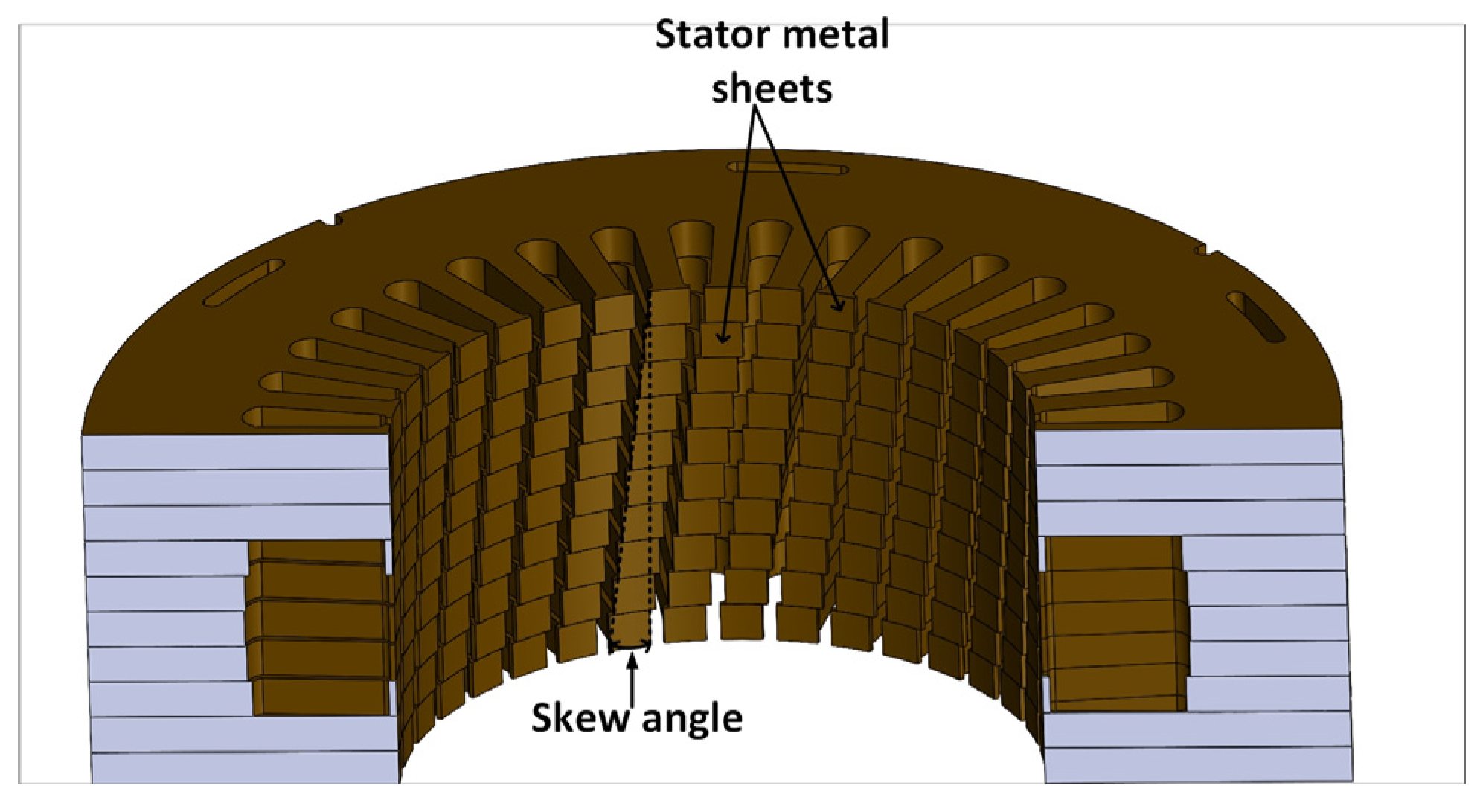
On the basis of the presented articles and considerations, a model of the proposed machine with hybrid excitation was created. In order to improve the parameters of the machine, a stator slot skew was additionally introduced (
Figure 4).
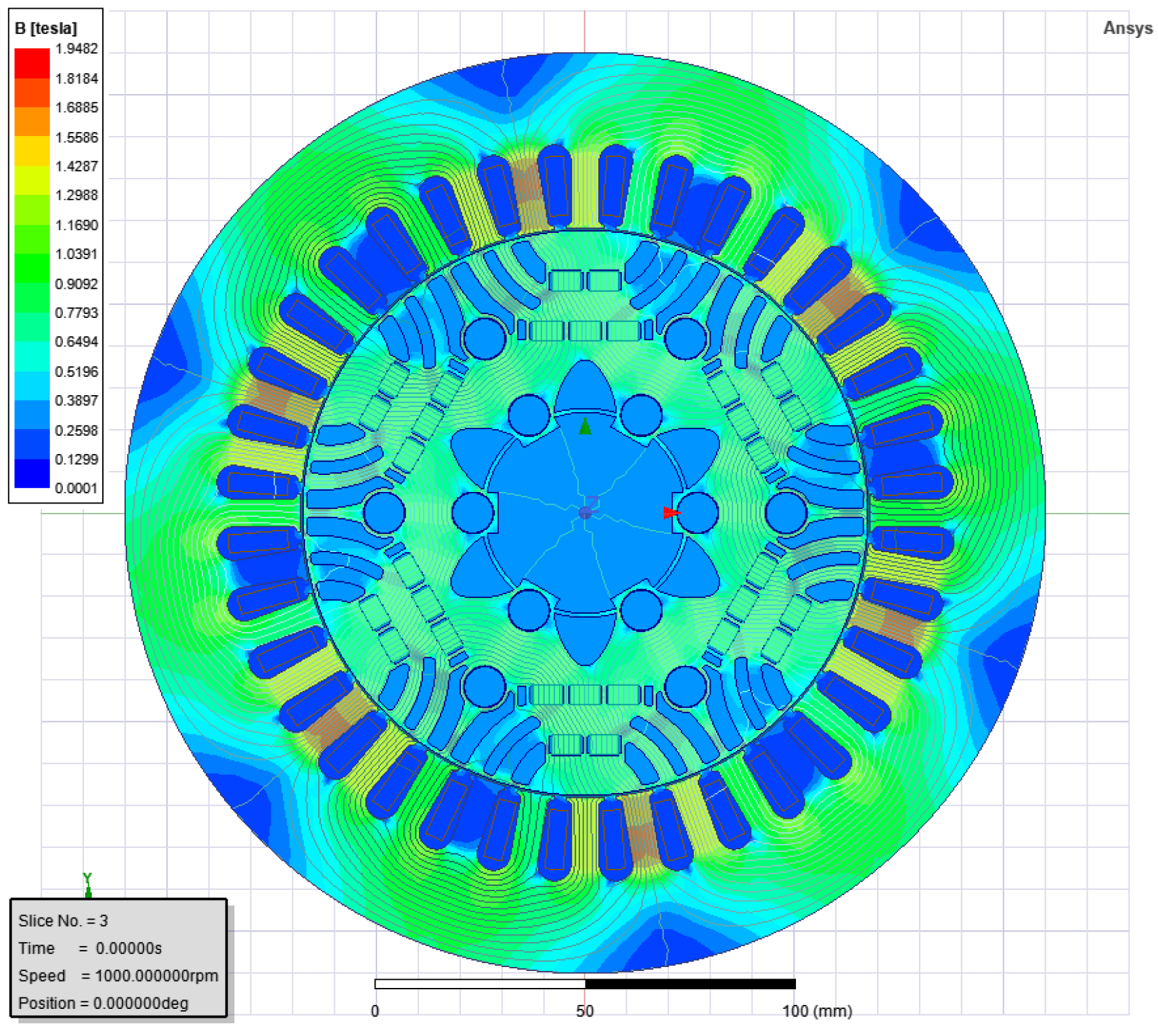
The FEM model of the machine was created in Ansys Electronics Desktop 2021 R2 (
Figure 5).
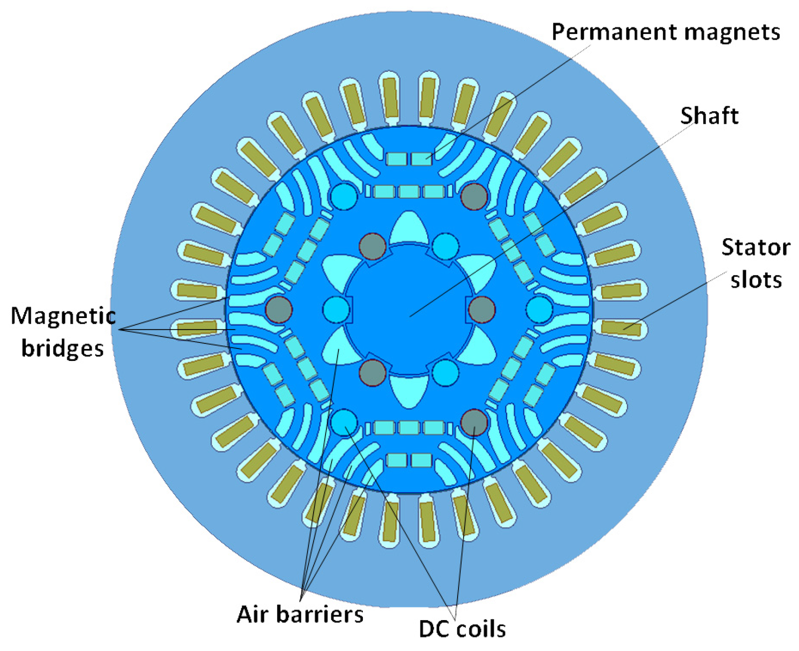
Figure 5 shows the selected operating point of the machine. In the areas of
Figure 5, which are materials that are poorly conductive of magnetic flux (such as copper and air—shaft and magnetic barriers—see
Figure 1), the field will have a low induction value, hence the color of these areas are blue.
The results presented in the article concern a low-power machine (4–5 kW). Its most important geometric dimensions, outer diameter: 220 mm, rotor diameter: 135 mm, and length of active parts: 190 mm. The project uses commercially available neodymium magnets with dimensions of 4.5 × 7.0 in the cross-section. The design has 36 slots and 6 poles, so the machine has 2 slots per phase per pole.
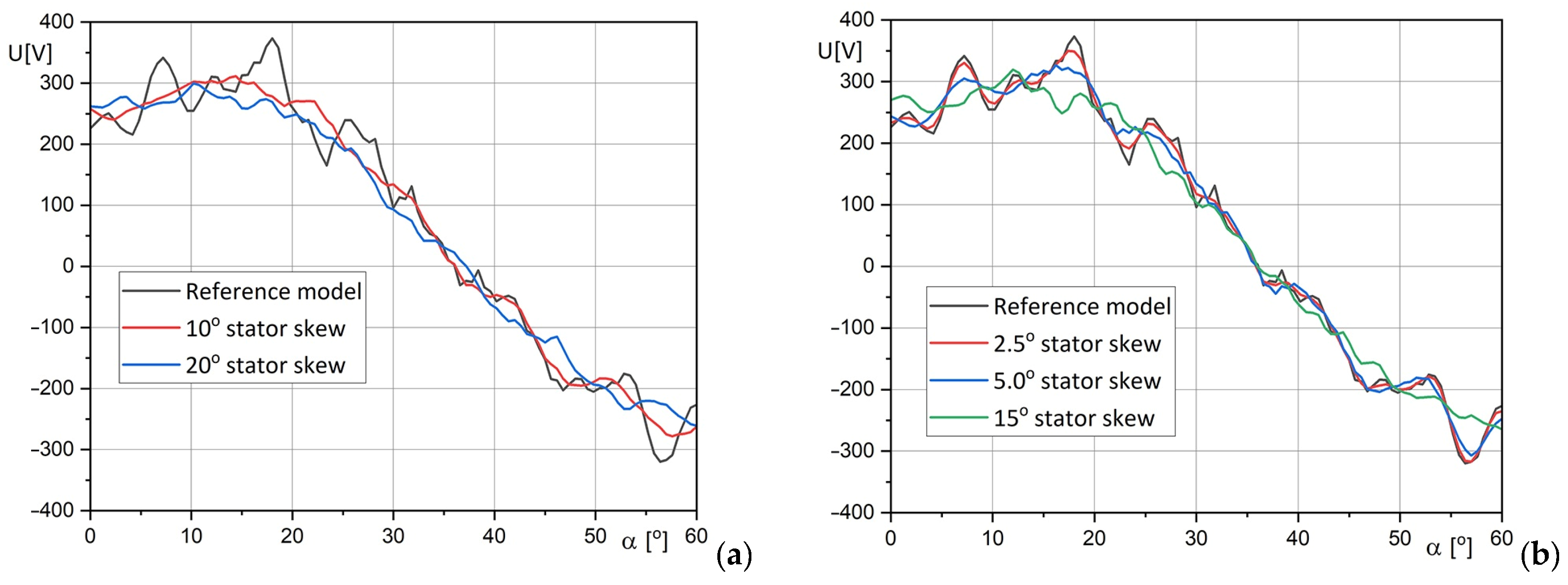
The skew enables the value of the cogging torque created by the interaction of the permanent magnets with the stator to be minimized. It can be applied to both the machine stator and rotor. The simplest type of skew is the so-called “continuous skew”, where each slot is offset from the next by a constant angle. For the purpose of the analysis, a reference model was created with no skew, 2 models with a continuous integer skew of 10 and 20 degrees, which corresponds to a value of 1–2 slots, and 3 models with a non-integer skew of 2.5, 5 and 15 degrees, which corresponds to a skew of 0.25 slots, 0.5 slots and 1.5 slots.
Figure 6 shows the waveforms of the induced voltage for integer and non-integer skews for an example load current
of 4 A and excitation current
of 0 A. For comparison, the dashed line indicates the reference model. It can be observed that as the value of the skew angle increases, the waveform becomes “smoothed”. In addition, the skews of 2.5 and 5 degrees allow for a reduction of the induced voltage pulsations. For a skew of 15 degrees, a slight deformation of the waveform can also be observed.
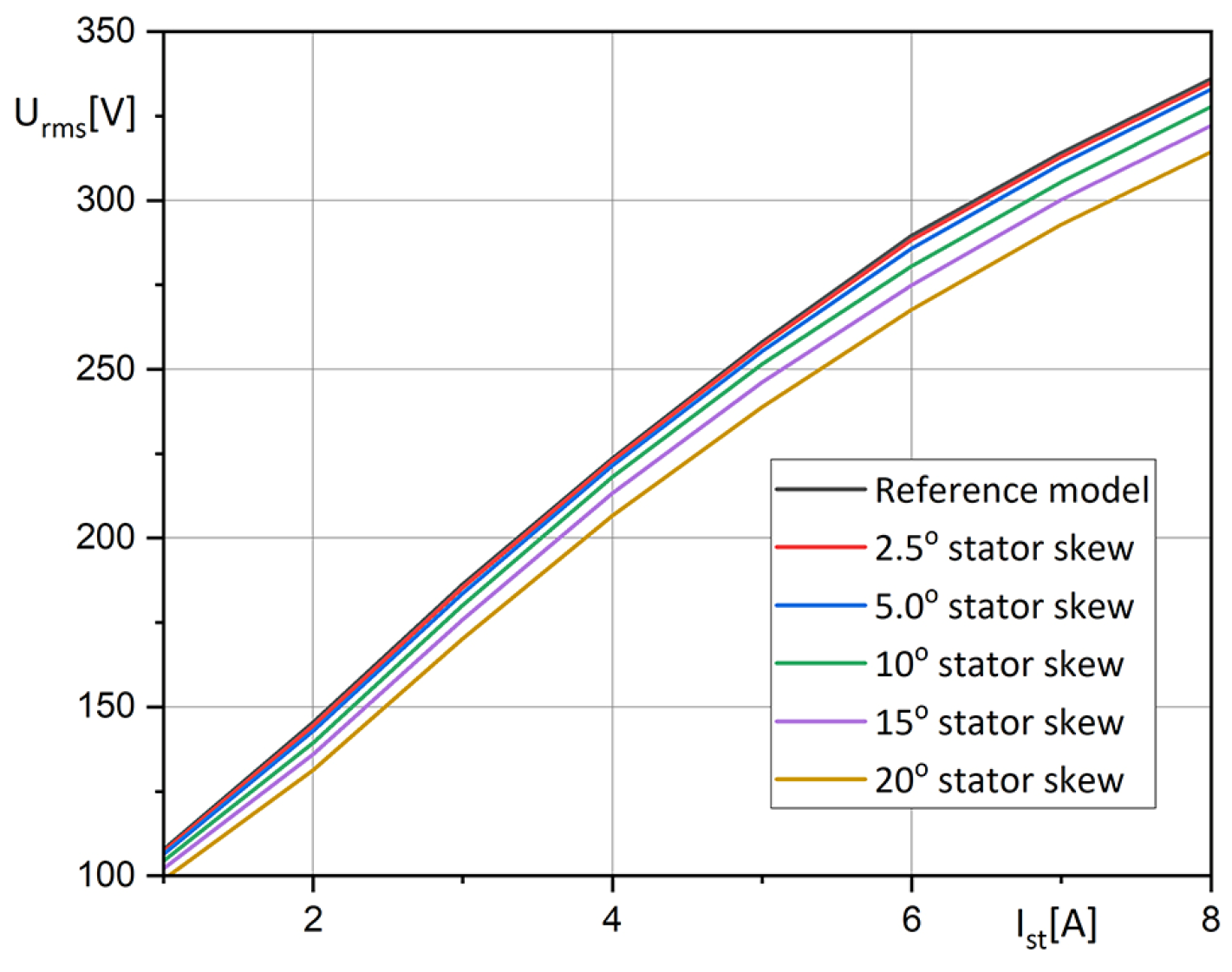
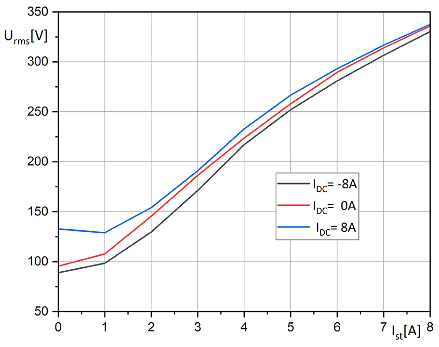
Based on the data obtained, a characteristic curve indicating the value of the induced RMS voltage for different values of the load currents for a coil current of 0 A, was obtained for different values of the skew (
Figure 7). It can be observed that the highest RMS voltage value is for the reference model and decreases with increasing the skew angle.
The obtained electromagnetic torque waveforms for different values of the skew allow for the visualization of its influence on the minimization of electromagnetic torque pulsations. From
Figure 8, it can be seen that the torque pulsations decrease with the increasing angle of the skew. In the case of models containing an integer skew, it can be seen that this effect is higher, and the waveforms are less distorted than in the case of non-integer skews. In addition, for skews of more than 10 degrees (1 slot) there is a large distortion of the obtained waveforms.
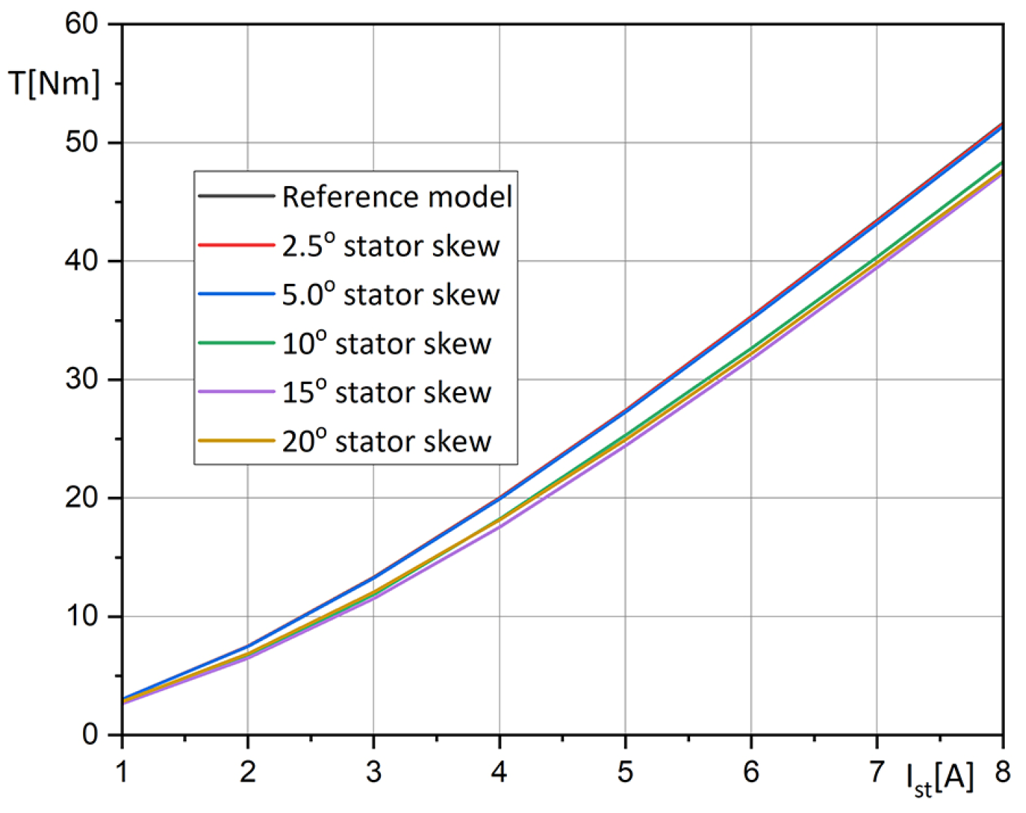
From the characteristics of the mean value of the torque as a function of the stator current for different values of the skew (
Figure 9), it can be seen that the reference model has the highest mean value of the electromagnetic torque produced. The value of the electromagnetic torque decreases with increasing skew angle, except for the value of 15 degrees (1.5 slots), when it reaches the lowest value.
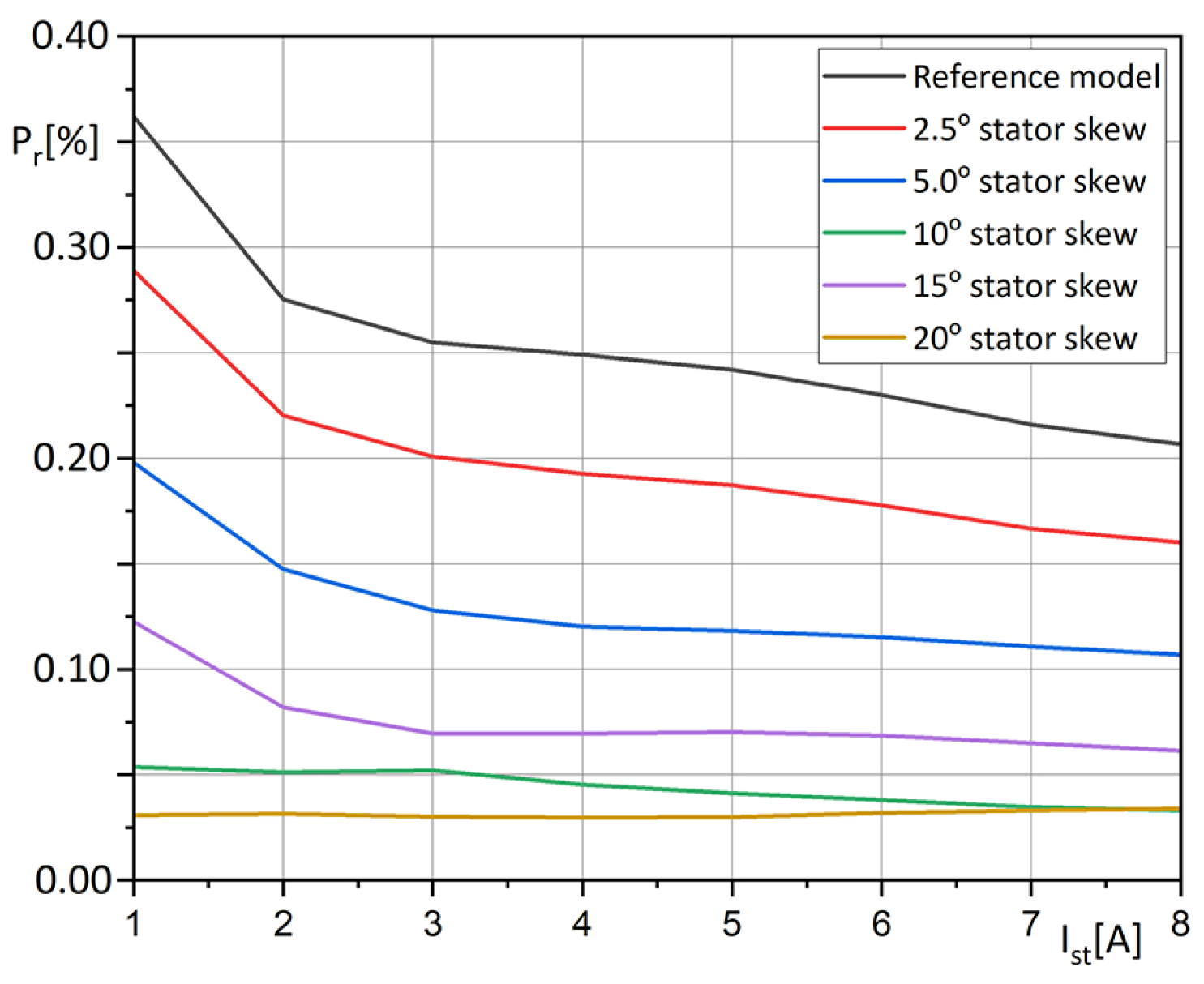
Figure 10 shows the maximum content of pulsations in the torque waveforms for different values of the stator current. The use of the total skew is most effective in minimizing the pulsations of the obtained electromagnetic torque. The pulsation ratio
is defined as the ratio of half the difference between the maximum and minimum torque values to their mean value for a given stator current and is given by the formula:
where:
,
is the maximum and minimum electromagnetic moment for a given stator current, and
is the average torque for a given stator current.
The use of a skew of 20 degrees (2 slots) enables the reduction of the pulsations from values of 0.2–0.35 to values below 0.05.
Based on the created FEM model, simulation studies were also carried out in terms of the electromagnetic field control. For this purpose, the DC coil present in the machine rotor was supplied with DC currents equal to −8, 0 and +8 A. The results obtained for the mean induced voltage are shown in
Figure 11.
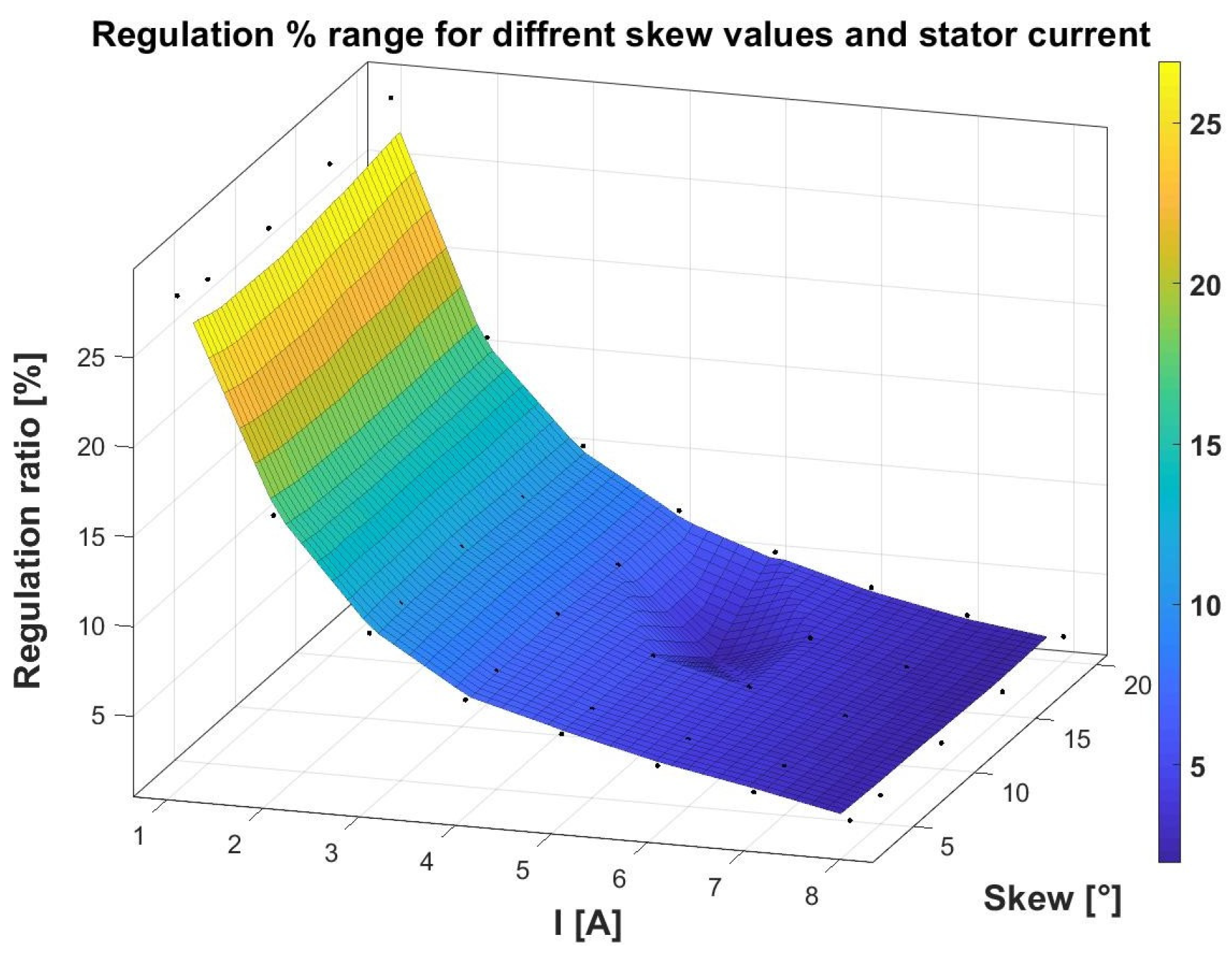
The regulation ratio was tested for the values of stator skew 2.5°, 5°, 10°,15°, 20° and stator rms currents (1 A to 8 A). The regulation ratio
defines the percentage ratio of the rms value of the induced voltage in the range of field strengthening (
) to the reference value (
) and is given by the formula:
where
is the average voltage value for the excitation current of 8 A DC, and
is the average voltage value for the excitation current of 8 A DC.
The results obtained are presented in the form of a 3D diagram in
Figure 12.
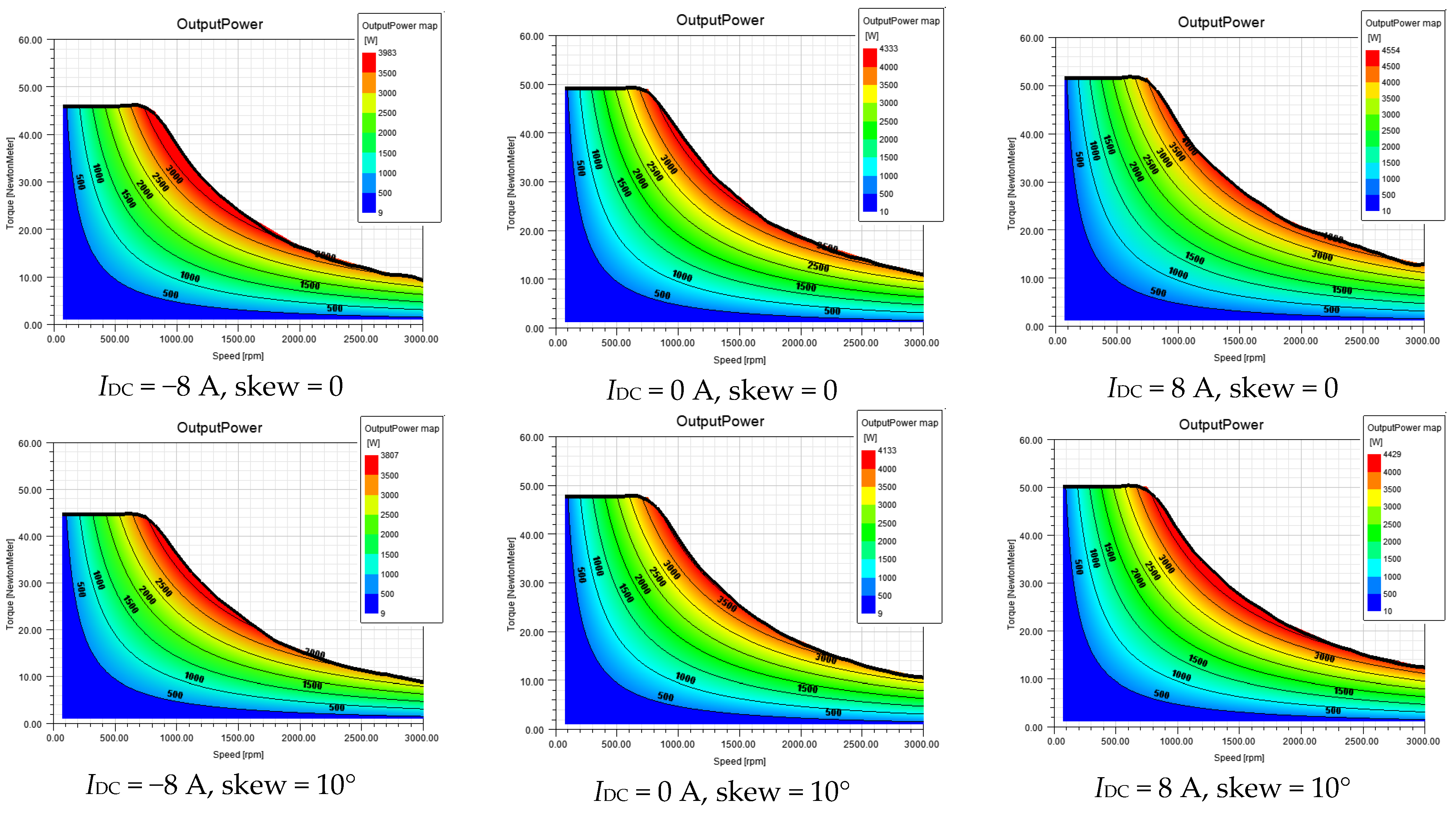
To summarize, the research efficiency maps and machine power maps of the proposed machine have been calculated. These maps were calculated for models without a slotted skew and with a skew of 10°. For this purpose, the Machine Toolkit, which is implemented in the Ansys Electronics software, was used. The following assumptions were made:
- -
The machine’s phase path windings are star-connected,
- -
The maximum supply voltage is U = 400 V rms phase-to-phase,
- -
The maximum supply current is I = 8 A,
- -
The selected control strategy is MTPA (maximum torque per ampere),
- -
The phase winding resistance R = 1.8 Ω.
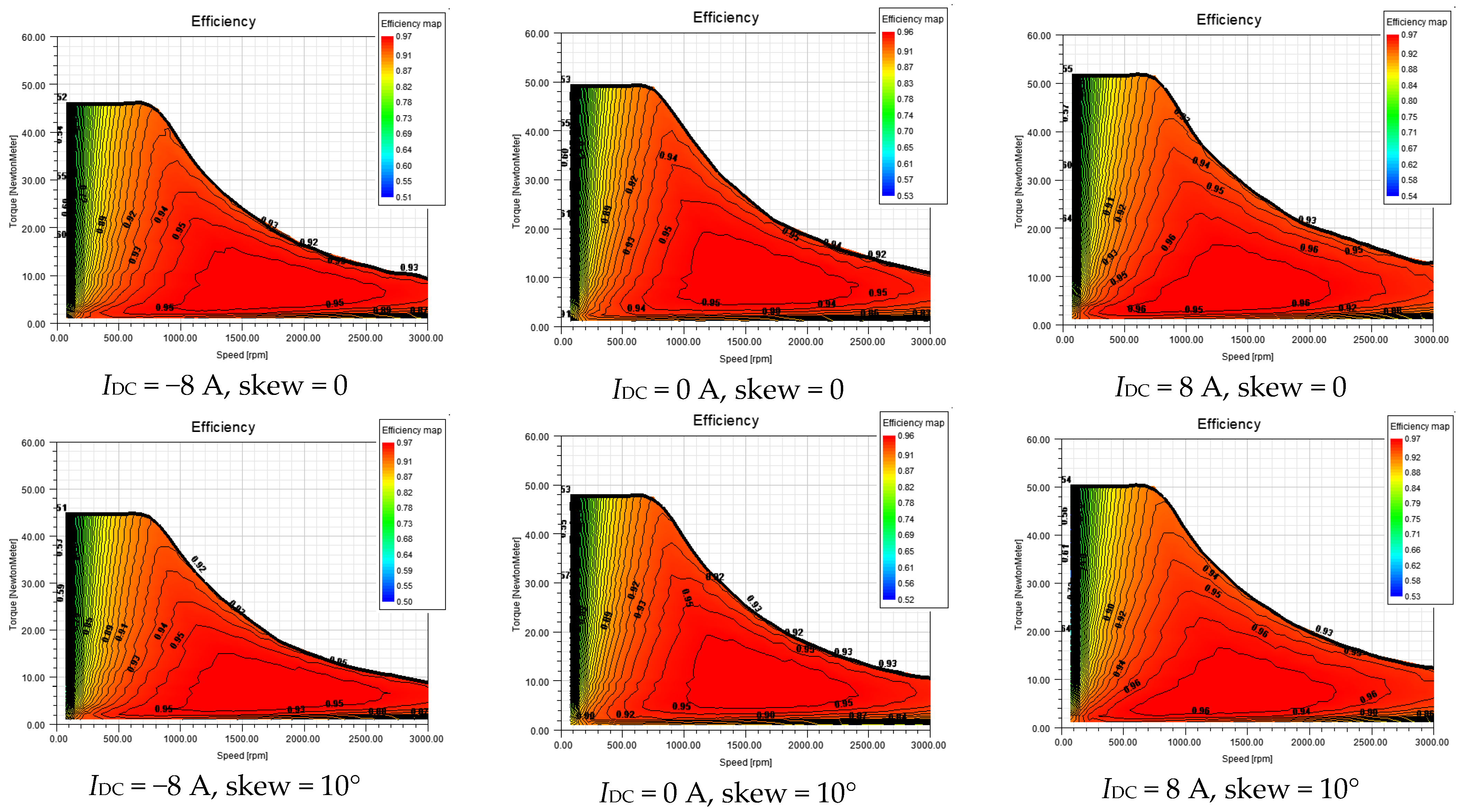
Figure 13 shows the power maps of the machine, while
Figure 14 presents the machine efficiency maps.
The research shows that in the presented solution of the machine, the additional excitation system can effectively increase the output power of the machine (in the range of flux increasing), but also reduce it in the case of flux weakening. In terms of increasing the flux in the rotor, it is possible to increase the output power by more than 200 W, while when weakening the field this power can be reduced even by more than 300 W.
The obtained results concerning efficiency maps are satisfactory. The maximum efficiency value changed in a small range, while in
Figure 14 it can be seen that the area of maximum efficiency moves on the map depending on the current in the additional coil.
On the basis of the research carried out, the following features of the analyzed machine should be emphasized:
The increase in the stator skew value causes a decrease in the RMS value of the induced voltage and reduces its pulsations.
The highest value of the torque pulsations was recorded for the reference design and the lowest value of less than 0.05 of the torque values for the design with a skew of 2 slots (20 degrees).
The use of a stator skew reduces the value of the electromagnetic torque.
Incomplete skew affects the resultant torque to a lesser degree.
Skew over 1 slot (10 degrees) causes additional distortion of torque waveforms.
As the stator current increases, the flux control range decreases, due to an increase in the field component coming from the current flowing through the stator windings.
In the results shown in
Figure 12, it is possible to see irregularities in the characteristic occurring for currents in the range 5–6 A and slant values above 10 degrees.
On the basis of the results obtained, it should be noted that the skew value generally has little effect on the adjustment range of the machine.


