Article

Reliability of Microinverters for Photovoltaic Systems: High-Temperature Accelerated Testing with Fixed and Cyclic Power Stresses

1
Photovoltaic Reliability Laboratory, Arizona State University, Mesa, AZ 85212, USA
2
Sandia National Labs, Albuquerque, NM 87105, USA
3
Poundra LLC., Tempe, AZ 85281, USA
*
Authors to whom correspondence should be addressed.
Energies 2023, 16(18), 6511; https://doi.org/10.3390/en16186511
Submission received: 11 July 2023 / Revised: 25 August 2023 / Accepted: 8 September 2023 / Published: 9 September 2023
(This article belongs to the Section A2: Solar Energy and Photovoltaic Systems)

Abstract

:
This paper presents an extended, accelerated reliability evaluation of forty microinverters, module-level power electronic (MLPE) units for photovoltaic (PV) modules. The forty microinverters were stressed at two static temperatures (65 °C and 75 °C) with two input power profiles (fixed and cyclic power). These power profiles were employed to replicate field-use conditions closely. The accelerated testing was performed for an extended duration (over a period of 15,000 h) to determine the acceleration factor and estimate the service life of microinverters in field-use conditions. Electrical performance and thermal data were continuously monitored during the experiment for all the microinverters. The accelerated stress testing had no failures even after 15,000 h of operation. Using the Arrhenius life-stress model along with average field-measured temperature and military handbook-based analysis, it was estimated that the microinverters should be able to survive for 24–48 years during their service life in field conditions, with a reliability of 74%, having a lower one-sided confidence bound of 95%, obtained using the classical success run approach. Moreover, the lifetime of microinverters was statistically analyzed using a Weibull distribution model. Weibull slope factors were used to estimate a range of characteristic lifetime periods and the reliability of the microinverters with a 95% lower one-sided confidence limit, demonstrating a similar or even exceeding the lifetime of the associated PV modules of 25 years.

1. Introduction

Module-level power electronic (MLPE) devices have been increasingly incorporated in photovoltaic (PV) systems in recent years [1]. MLPE units, such as microinverters (MIs), are power electronic devices designed to optimize the input power from individual PV modules to maximize the energy harvest in a PV system. With the increase in PV generation [2] and capacity [3], the demand for MLPEs is increasing [4] for distributed generation systems [4]. According to the Industry Research Report, MLPE markets will enjoy a compound annual growth rate of 14.7% in the period of 2021–2026, with a market share projected at USD 2250 million by 2026 [5].
MLPEs in PV systems offer advantages by improving a system’s energy production. They electrically isolate the PV modules from each other so that the output of an entire array remains unaffected during partial shadings [6,7] or entire module failures [8]. According to the NREL report, MLPEs can potentially decrease the energy losses caused by the partial shading [9] of PV modules by 20–35% [10] while eliminating energy losses due to PV module orientation mismatch [11]. Most MLPEs offer performance monitoring at the module level, along with a diagnostic functionality, to detect and eliminate the occurrence of potential-induced degradation (PID) [12] using the historical output power and voltage measurements of each module due to individual module-level monitoring [13]. Each MLPE unit can harvest the optimum power by performing MPPT for its connected module [8], while microinverters can convert the output power of a PV module to a grid-compliant AC power [14]. Microinverters have the potential to perform at high efficiency [15], and their power rating capacity is continuously being pushed to higher limits with the improvement in photovoltaic module technology [16].
Despite their benefits, MLPE devices have distinct disadvantages compared to traditional inverter systems. Their exposure to extreme environments during the day due to their proximity to PV modules in actual field conditions can reduce their efficiency [17,18] and negatively impact their reliability [19], which can contribute to failures [20]. Moreover, customers expect MLPE service life and warranties equivalent to PV modules (25 years) since, in most cases, MLPE units are sold paired with the modules. Large-scale PV systems can have millions of modules (and the same number of MLPE units); so, it is challenging to check and replace the failed MLPE units regularly. Therefore, it is essential to understand the lifetime and the statistical reliability of MLPE units for the operation and maintenance schemes of large PV systems. While most of the reliability studies conducted focus on the performance of MLPE units [21,22], few have conducted accelerated tests. These include work [19] that conducted MLPE testing for a short-term (1000 h) and [23] that conducted a range of accelerated testing protocols, including static temperature testing on various MLPE topologies for a mid-term (nearly 3500 h) reliability on a limited number of microinverter units. However, ref. [24] performed a comprehensive time-to-failure study focusing on the reliability of MLPE devices, where a significant number of units was subjected to extensive stress testing for 6400 h at elevated static temperatures. The data showed a modest degradation percentage, with no unit exhibiting failures beyond a 5% threshold. The authors of [24] projected a real-world lifetime of 39–73 years with a 79% reliability. However, cyclic power profiles revealed a considerable decline in lifespan estimates, reducing it to 9–12 years. The Weibull distribution analysis further supported this notion, emphasizing a predicted increase in the degradation rate over time. In the present study, we investigate a statistically significant number of microinverters (40 units) over a long term, 15,000 h, to closely replicate degradations and failures of microinverters over the warranty period of 25 years or more.
High temperature is a major cause of the failure of electronic components, which can result in numerous failure mechanisms [25]. Reliability plays an important role in the cost of power conversion devices [26] that are responsible for critical failures and can have numerous failure modes [27]. MLPEs are complex devices with various topologies, control systems, and electronic components, having a significant number of components [23]. Since only little independent field data or accelerated test data are publicly available on the reliability and lifetime of MLPE devices, high-temperature-operating life testing is independently performed in this study to estimate the reliability and lifetime of the microinverters. A sample size of at least twenty-two is commonly used in the industry [28] for a typical reliability requirement of R90C90 (90% reliability and 90% confidence interval). In this work, the quantification of the statistical reliability evaluation is improved by investigating the reliability of a statistically significant number (N = 40) of microinverters at high static temperatures with fixed and cyclic power profiles for a long-term duration of over 15,000 h.
The objective of this work is to estimate the service life of microinverters during field operation, which will enable stakeholders to build confidence in the design and optimize warranty regarding the most prominent environmental stressor of static heat. Additionally, the research introduces a conceptual framework, in which the reliability derived from high static temperatures acts as an upper boundary or “ceiling”. This suggests that the real-field reliability of microinverters might exhibit lower thresholds, underscoring a potential divergence between lab-induced stresses and multifaceted real-world stressors. Crucially, this study adopts a deliberate focus on thermal failure mechanisms only and acknowledges that other failure mechanisms, especially those common in diverse operational environments, are not systematically investigated. Hence, this study lays the groundwork for a comprehensive evaluation of microinverter reliability in different scenarios and emphasizes the existing knowledge gap concerning microinverter lifespan in high static temperature contexts.

2. Experimental Testing Setup

A total of 40 units were evaluated under high static temperatures of 65 °C and 75 °C at fixed and cyclic power profiles to estimate the field-use lifetime of microinverters. The upper test temperature of 75 °C was selected since this is slightly below the derating temperature limit of the units specified by the manufacturer. The lower test temperature of 65 °C was selected since this is higher than the maximum field-use operating temperature [29]. Microinverters, attached to the rear of PV modules, often face temperatures above usual outdoor levels. Studies have shown that, during peak sunlight, they can reach around 65 °C [29]. This is typical for moderate climates. The 75 °C test represents hotter conditions, such as a scorching summer day when the PV modules become extremely hot. Since microinverters are closely attached to these modules, they too can become this hot. Testing at these temperatures helps to understand how certain materials in the microinverters might change or wear out, impacting their performance.
The microinverters were distributed in sets of 10 units and placed in four convection ovens with regulated ambient temperatures. Each oven had a different testing profile based on the input power configuration and the test temperature, resulting in a total of four test profiles (thus, four ovens), as shown in the MLPE testing plan in Figure 1. A testing setup was established at ASU-PRL [30] for this large-scale MLPE testing purpose, in collaboration with Sandia National Laboratories and Poundra.
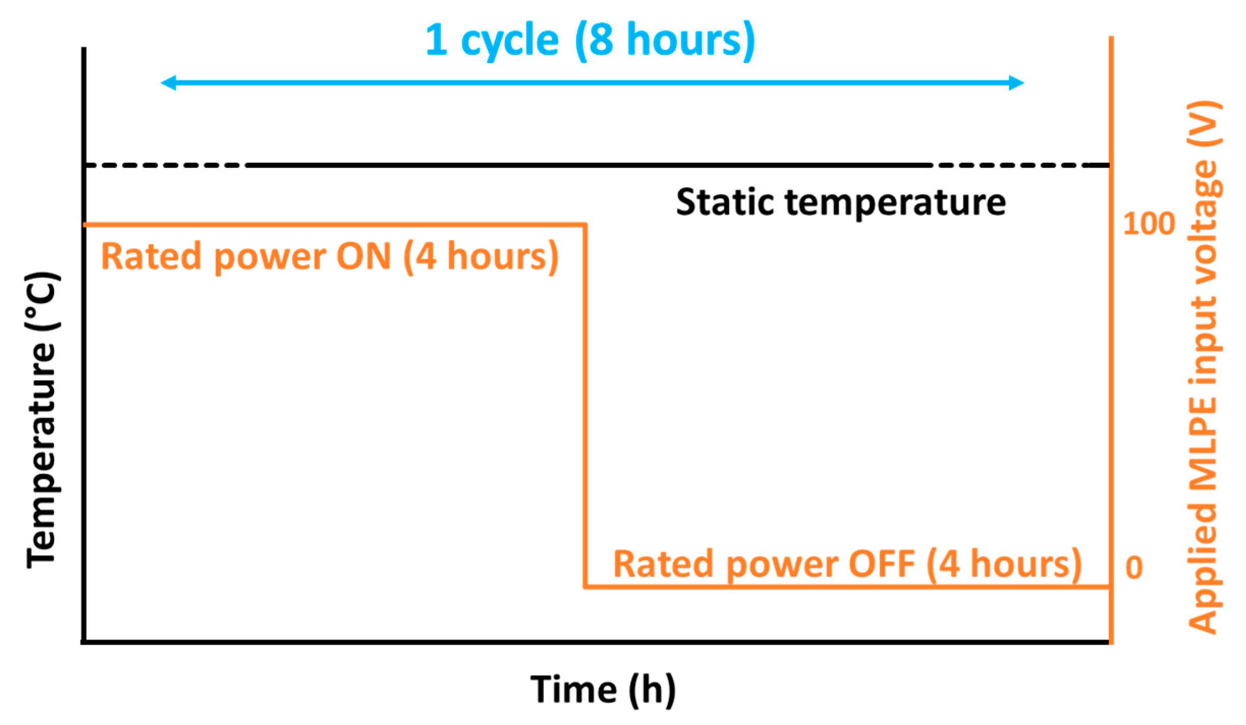
During the high static temperature test, all ovens were kept at their respective constant ambient temperature setpoints, slightly lower than the units’ target temperatures of 65 °C and 75 °C (in the respective ovens) to compensate for the heat generated by the microinverters. This resulted in a high static temperature stress on the units without the possibility of derating. Moreover, DC power supplies were used in the testing setup to provide a stable and continuously rated DC input power to the microinverters. In this study, half of the microinverters were supplied with a fixed-rated input power, while the other half were supplied with a cyclic-rated input power, as shown in Figure 1. To simulate the accelerated field-use conditions, the cyclic input power was employed in an automated manner in the testing setup, where the input power to the units was provided for the first four hours in each cycle. For the subsequent four hours, the test units were powered off, and no input power was provided (shown in Figure 2), resulting in a total of 3 cycles per day. For the fixed power profiles, a continuous input power was supplied to the test units during the entire cycle. The cyclic input power helps to determine the power cycling effect on the microinverter’s lifetime.
The study used a cyclic power profile to mimic a PV module daily energy fluctuations, accurately representing a microinverter’s daily operations with a PV module. Meanwhile, the fixed profile simulates a full sunny day, continuously stressing the system. This cyclic profile also imitates real-life scenarios, such as cloud cover, using actual data from various locations to ensure authenticity. It even captures seasonal changes and quick sunlight variations. Power profiles are linked with a microinverter’s thermal environment, influencing its performance and lifespan. Our tests aimed to represent the different conditions microinverters face in real-world situations. Furthermore, the units in cyclic power profiles experienced a shallow cyclic temperature profile in the ovens compared to the profiles of fixed power due to the power cycling of the units; however, the average unit temperature was maintained at the target temperatures of 65 °C and 75 °C in cyclic power profiles without any significant temperature variations.
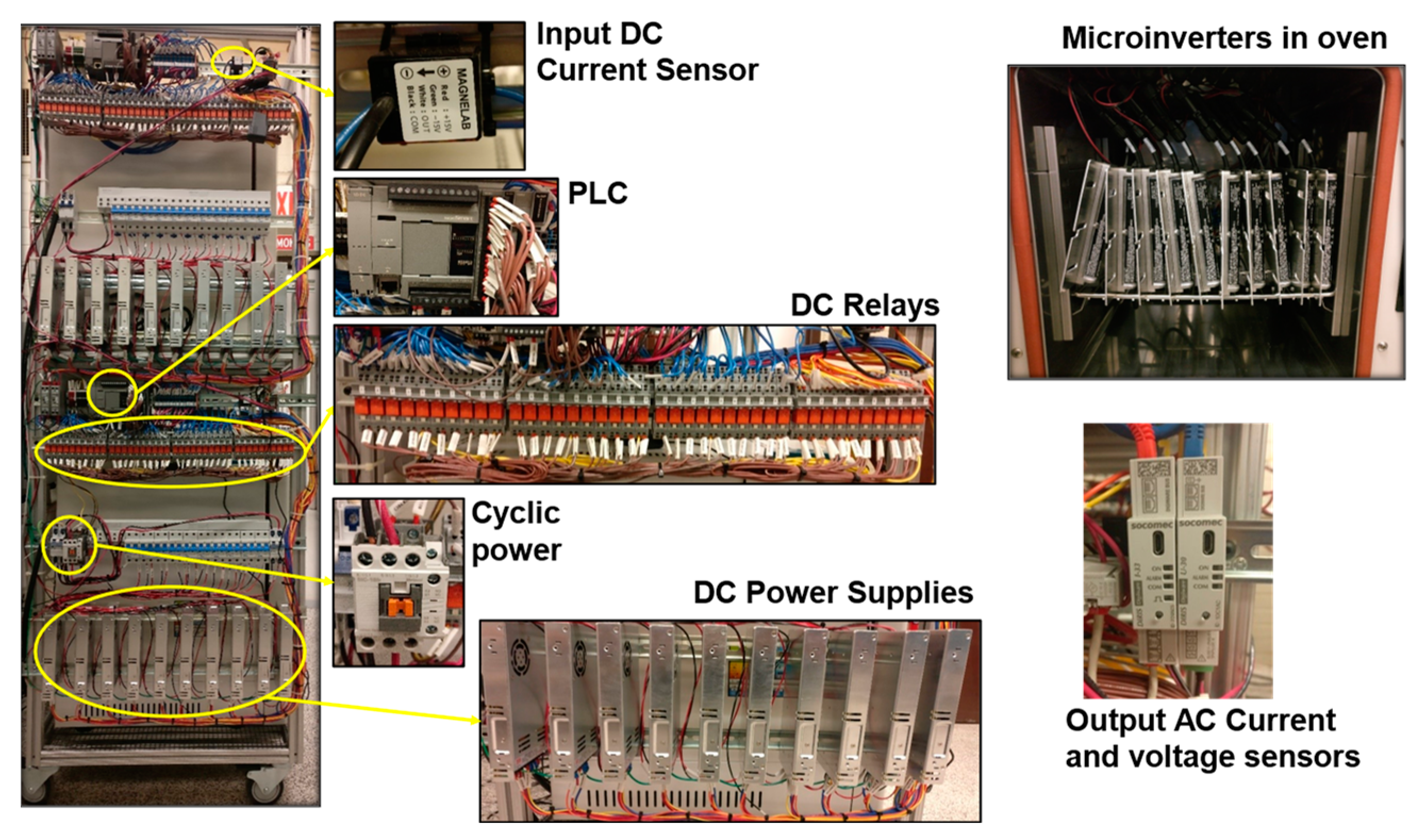
Figure 3 illustrates the MLPE testing setup along with the microinverter units shown inside an oven. The temperature settings for all the ovens were programmed in such a manner that a static ambient temperature was maintained inside the respective ovens all the time to achieve the test units’ lower and upper target temperatures of 65 °C and 75 °C, respectively. Programmable logic controllers (PLCs), in combination with ethernet switches and relays, were used for the power cycling operation. A power monitoring device was used to measure the electrical parameters (voltage, current, and power) at both the input and output of each microinverter to compare between the different power profiles and test temperatures. A thermocouple was attached to one microinverter in each oven to record the unit temperature, representing all unit temperatures in that oven. Moreover, a datalogger was used to continuously record the electrical and thermal data with a time step of twenty seconds.
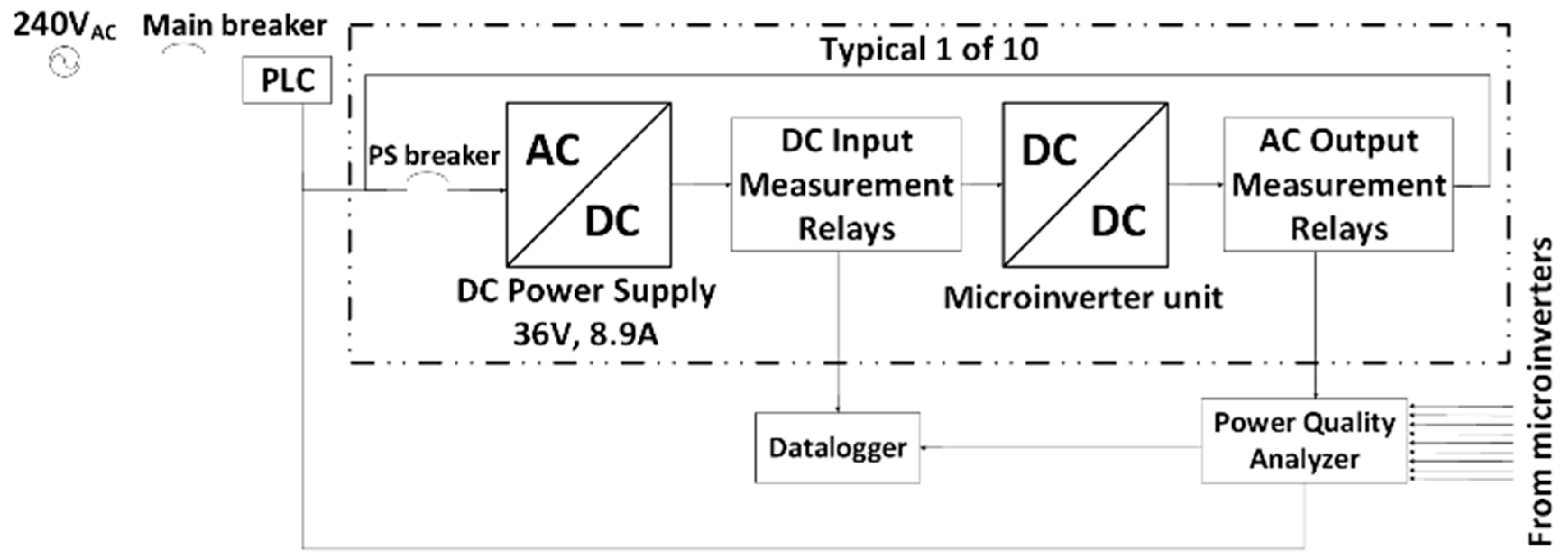
A block diagram of the electrical connections for the microinverter testing setup is presented in Figure 4, showing one microinverter unit out of ten units per test profile. The microinverter testing setup has a distributed architecture, where each module (DC power supply in this experiment) has its own microinverter unit. Ten microinverters are placed in each of the four ovens and connected in a parallel configuration with the grid.

3. Results and Discussion

The results of this study are divided into three sections. Section 3.1 discusses the performance of the microinverters in terms of the output power efficiency with respect to high static temperature testing. Section 3.2 uses the Arrhenius approximation to estimate the field-use lifetime of the microinverters, and Section 3.3 uses the Weibull distribution model to estimate the characteristic life and reliability of the microinverters with respect to time.

3.1. High Static Temperature Testing for the Microinverters

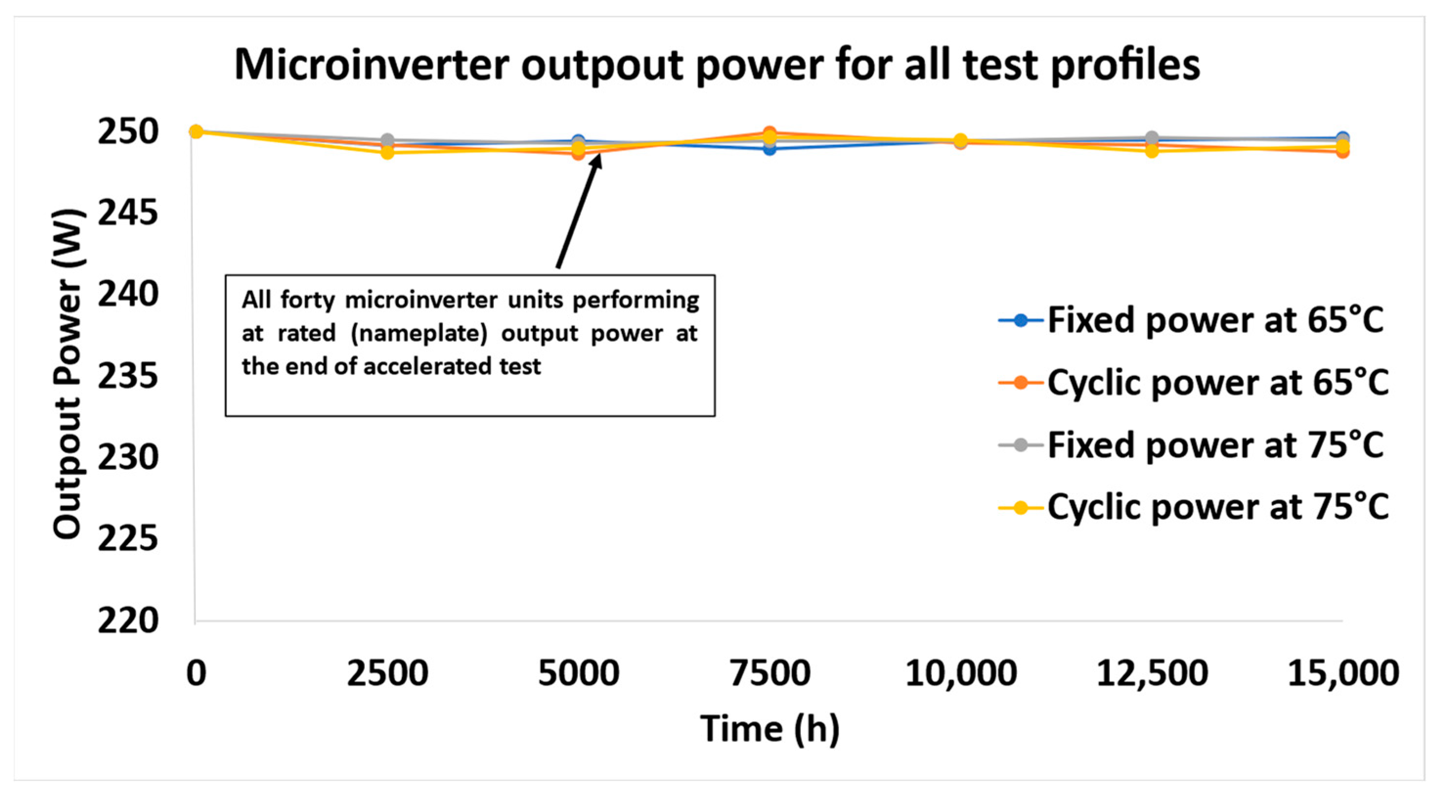
High static temperature is responsible for overheating the internal electronic components, causing device failures and reducing lifetime. Microinverters are significantly complex devices having multi-stage power conversion, control, protection, and communication circuitry. The components susceptible to heat are power semiconductors, electrolytic capacitors, wire terminals, and connectors [31]. Based on the type, a single component, such as the capacitor [32] or metal-oxide semiconductor field effect transistor [33], can have several failure mechanisms that depend on environmental stressors, such as voltage and temperature, and its electrothermal environment. Hence, the total number of failure mechanisms for a complete microinverter system can range in the thousands. The IEC 62093 standard [34] defines failure for power conversion devices as degradation in the output power of more than 5% from the nameplate rating or device non-functioning. However, the accelerated stress testing of microinverters for 15,000 h in this study ended without any failures based on the defined failure criteria. The periodic characterization of the rated output power was conducted at every 500 h for all the units, and no significant change in the rated output power was evident. All the microinverter units were operating at the rated (nameplate) output power during and at the end of the accelerated test, as illustrated in Figure 5. However, during testing, small variations were observed in the measurements of the input current, voltage, and output power, which caused slight variations in the output power for the units. These variations were likely due to small errors in the measurement instrumentation used during the test, rather than any significant issues with the units themselves. Furthermore, all forty microinverters passed the insulation and functionality tests at the beginning and the end of the experiment.
Prolonged operation at extreme temperatures, while not immediately indicative of failure in our tests, could erode the insulation layers over time, potentially culminating in short circuits. Such incidents could compromise component integrity, diminish efficiency, and even pose safety risks. Similarly, electrolytic capacitors, particularly those in the DC link, are vulnerable to drying or swelling under pronounced thermal and voltage strains. Consequently, these capacitor anomalies could jeopardize inverter functionality, either slashing power output or damaging adjacent components via voltage surges. Power semiconductors, such as MOSFETs and diodes, under sustained thermal and electrical pressures, may undergo gate oxide deterioration or junction attrition [24,35]. Such semiconductor degradation could escalate conduction losses, subsequently reducing efficiency and inducing added heat, hastening their degradation. Additionally, the combined effects of elevated temperatures and voltage can instigate delamination in the printed circuit boards (PCBs), especially in intricate multi-layered configurations. This could lead to trace breaks, disrupting inverter operations. Lastly, connectors and contacts, subjected to environmental variables, may experience corrosion, oxidation, or fretting, elevating their resistance. This heightened resistance might then induce further heating and voltage discrepancies, impinging on the microinverter’s holistic performance.
Box plots were generated to illustrate the median of normalized efficiency (unit efficiency normalized to its own efficiency at time zero) at the end of accelerated testing. Each box plot in Figure 6 represents the median efficiency of ten microinverter units for a single test profile (temperature and fixed/cyclic power). The final efficiency results were measured at room temperature with a rated input power supplied to the test units. The normalized efficiency for microinverters ranges above 99% for all test profiles. For fixed and cyclic power profiles at 75 °C, the efficiency spread is more than the 65 °C test profiles due to the test temperature being close to the unit derating temperature. Microinverter units gradually derate beyond 75 °C to avoid overstressing its internal electronic components and thus operate at a reduced output power to protect themselves from accelerated aging. Moreover, the total harmonic distortion in the AC output current was lower than 2.5% for all the units. This indicates no significant change in the waveform for the stressed microinverter units, ensuring an acceptable power quality even after 15,000 h of accelerated stress testing at high static temperatures. Small errors in the input current and voltage and the output power measurements resulted in the variations observed in the efficiency measurements, although no long-term degradation or occurrences of failures were observed in the stressed units. Furthermore, the cyclic power profile in this study did not have a significant effect on the output power of microinverter units during the accelerated testing at both higher and lower test temperatures. However, with only two static test temperatures applied in this study, further analysis based on multiple stress temperatures is required to validate this observation.
In this study, the accelerated testing of microinverters performed at high static temperatures for extended durations (over a period of 15,000 h) resulted in zero failures, as illustrated in Figure 5 and Figure 6. This demonstrates that microinverters can survive for longer lifetimes in field conditions than the traditional (string or central) inverter system (having high failure rates). While a few microinverters may need replacement during field-use operation, they are typically less in number [36] due to their high reliability [37] and advancements in semiconductor fabrication, which enables operation at high temperatures [38]. Moreover, the electronic assembly of microinverters stressed in this study was protected by a thick enclosure casing, which was entirely filled with a dense layer of encapsulation material. This increases the weight of the microinverters, but provides environmental isolation and mechanical support to the internal components.

3.2. Estimated Field-Use Lifetime for the Microinverters

The Arrhenius approximation for accelerated testing was used to determine the service life of the microinverters in field-use conditions ( T T F u s e ) based on 15,000 h of stress testing T T F t e s t at the high static temperatures of 65 °C and 75 °C, represented by T t e s t (Kelvin). This model is represented mathematically as:
T T F u s e = T T F t e s t   e E a k 1 T t e s t 1 T u s e
In Equation (1), k represents the Boltzmann’s constant (8.61 × 10⁻⁵ eV/K), while E a and T u s e represent the activation energy and field-use temperature (Kelvin), respectively.
The proportionality factor e E a k 1 T t e s t 1 T u s e represents the acceleration factor (AF) in Equation (1). It is the ratio of the degradation rate at an elevated test temperature relative to that at a lower base temperature. An activation energy ( E a ) of 0.7 eV was assumed according to the military handbook [39] to determine the acceleration factors for the microinverters. This is a common approximation for silicon-based systems in the industry that includes most power conversion devices and is used for estimating the reliability and lifetime prediction of electronic components and systems [40].
Furthermore, to estimate the field-use temperature profile ( T u s e ) of the microinverters, the ASU-PRL weather station was used to obtain the ambient temperature for one year at Mesa, Arizona. Since MLPE units experience thermal stress during daytime operation, the ambient thermal data only included daytime hourly average temperatures. It is evident from [19,23,40] that the MLPE unit temperature is approximately 20 °C higher than the ambient one during field operation. The higher MLPE temperature can be attributed to the unit’s physical orientation and proximity to the PV modules and the air gap between the surface of the rooftop and the module. Hence, for the purpose of this analysis, we assumed that the temperature of the microinverters was 20 °C above the ambient one.
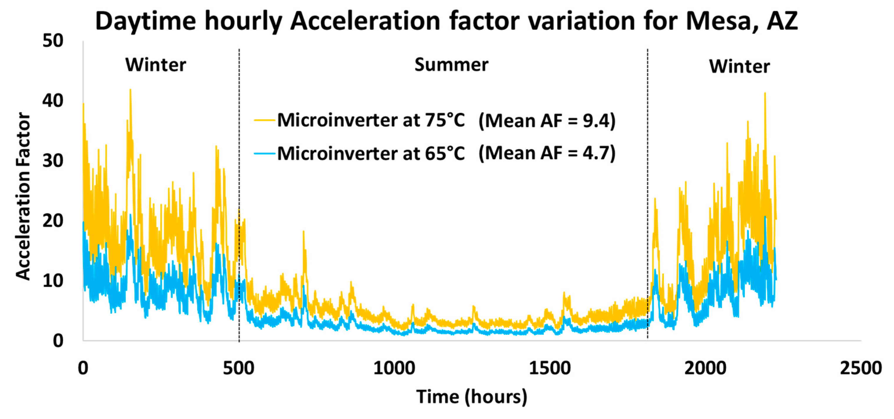
Due to the temperature variation in the field, a range of acceleration factors was obtained, as shown in Figure 7. This was obtained by compiling the daytime hourly average temperature (achieved by adding 20 °C to the ambient temperature obtained from the site of Mesa, Arizona) of the microinverters. An average field-use temperature ( T u s e ) of 44.5 °C was calculated for the microinverters with one standard deviation of 9.6 °C, and only daylight hours were included in this calculation. With this estimation, an average acceleration factor of about 4.7 for the 65 °C microinverter test profiles and 9.4 for the 75 °C microinverter test profiles were obtained, as shown in Table 1.
After the acceleration factors were determined based on the two test temperatures, the accelerated testing time of 15,000 h was translated to the field-use temperature (44.5 °C) using Equation (1) to yield an equivalent service life in the field. The accelerated stress hours of 15,000 for the microinverters translates to an equivalent of 70,470 h in the field for the accelerated stress profiles at 65 °C. For the accelerated stress profiles at 75 °C, an equivalent of 140,500 h in the field was estimated, as shown in Table 1. The accelerated stress testing of the microinverters conducted with a daily operation of 24 h is not concordant with PV systems. Thus, we assumed an 8 h/day operation for the microinverters. This translates the operational hours to 24 years for the 65 °C test profiles and 48 years for the 75 °C test profiles, as shown in Table 1.
As the accelerated test in this study resulted in no microinverter failures, a zero-failure test analysis [28] was performed to estimate the minimum reliability of the microinverters stressed at high static temperatures. The zero-failure analysis is a useful statistical tool to establish the minimum device reliability and is extensively used in the industry. A statistical confidence interval plays an important role in the interpretation of the estimated reliability, where a higher confidence interval reduces the likelihood of inaccuracy in the results [28]. Using the classical success run approach [41], the reliability of the microinverters based on the confidence intervals was estimated using Equation (2) and is expressed as:
1 C = i = 0 r n i 1 R i R n i
where the reliability R of n number of units with a confidence bound of C is represented based on the r number of failures. When the accelerated test results in zero failures, Equation (2) becomes:
1 C = R n
The estimated reliability with its corresponding confidence bounds for a sample size of n = 10 units (used per test profile in this setup) and zero failures is shown in Table 2. This table shows that the microinverter units stressed for 15,000 (h) in this study have a reliability of 85% with a statistical confidence bound of 80%. Alternatively, the reliability of the test units is considered 74% but with a corresponding confidence bound of 95%. Therefore, the reliability of the microinverters at 24 years (from Table 1) is 85%, with a one-sided lower confidence bound of 80%. Similarly, with a confidence bound of 95%, the reliability for the same microinverters at 24 years is 74%, as shown in Table 2. This demonstrates that the lifetime of 74% of the microinverters is at least 24 years, with a statistical lower one-sided confidence bound of 95%.

3.3. Reliability Analysis Using the Weibull Distribution Model

In this section of the study, the reliability and lifetime of the microinverters is statistically analyzed with the assumption of a Weibull distribution model since no microinverter failures were observed [42]. This analysis is used extensively in industry to evaluate lifetime and model the device’s reliability because of its flexibility to fit a wide range of shapes based on the empirical lifetime data. The Weibull cumulative distribution function F t , which represents the probability of the failure of the microinverters, is defined by its shape factor ‘β’ and the scale factor ‘η’ as a function of time from 0 to t, as shown in Equation (4) below.
F t = 1 e t η β
The Weibull shape factor β (also called the Weibull slope) estimates the distribution of failures and determines the phase in the life cycle (increasing, decreasing, or constant failure rates) of the microinverters. The Weibull scale factor η is known as the characteristic life and represents the time at which 63.2% of the microinverter population fails in field operation [43].
Since the accelerated stress test of the microinverters resulted in zero failures, the Weibull shape factor cannot be obtained from the empirical test data. Hence, we assumed the Weibull distribution of the microinverters, with the assumption of a value for the unknown Weibull shape factor β [42]. An assumed shape factor with a smaller value has a higher probability in the lower tail of the distribution and represents earlier failures [44]. Conversely, when a higher value is assumed for the shape factor, the product has a lower probability of early failures [44]. An assumed value for β is typically different from the actual β value (unknown). Therefore, employing a confidence interval in the analysis might not represent the entire uncertainty for a device’s lifetime and can make the device appear more reliable than what it actually is [44]. Parameters estimated with a lower one-sided confidence interval have a higher probability of being below the actual population values and are usually chosen as 90, 95, or 99% [44]. With such confidence intervals, a safe and validated lifetime can be estimated for the units [44]. Thus, for the purpose of the Weibull analysis in this study, we assumed four different values for the shape factor in the range of 1.5–7 with a 95% lower one-sided confidence interval, as shown in Table 3.
The scale factor η in Equation (5) was estimated using the equivalent field operational time (years) [42] of the microinverters. This was obtained using the Arrhenius equation in Equation (1) based on the accelerated test time of 15,000 h, as shown in Table 1. Based on the two test temperatures of 65 °C and 75 °C, the higher stress temperature translates to a more field-equivalent lifetime due to a higher acceleration factor value as compared to the lower stress temperature.
η   i = 1 n   t i β l n 1 C   1 β
The scale factor η was estimated using a 95% lower one-sided confidence interval C after a testing time period t where n number of microinverters were tested during the accelerated stress test. For fixed and cyclic power profiles at 65 °C, having a translated field-use operational time of 24 years, the scale factor is in the range of 28–53 years with a one-sided lower confidence interval of 95%, as shown in Table 3. Similarly, with an estimated field service life of 48 years, the scale factor is in the range of 57–107 years with a one-sided lower confidence interval of 95%, approximated using the assumed values of shape factors for the fixed and cyclic power profiles at 75 °C. Thus, a range of η was estimated, shown in Table 3, based on different field-use lifetimes and test temperatures.
Table 3 shows the assumed shape factors β along with the estimated reliability at 25 years, scale factor, and the statistical lifetime expectancy L p of the microinverters using the Weibull analysis. L10 represents the statistical lifetime expectancy of the microinverters providing a 90% reliability metric (probability of failure for 10% units). L50 is the statistical median life expectancy of the microinverters, where 50% of microinverters will fail during operation. The statistical lifetime expectancy [42,45] was obtained using Equation (6) below.
L p   l n   1 p 100     l n 1 C   i = 1 n   t i β 1 β
where L p represents the statistical life expectancy based on p percent failures. The microinverter units tested at fixed and cyclic power profiles at 65 °C have an approximate L10 lifetime of 12–21 years. Similarly, the microinverter units tested at fixed and cyclic power profiles at 75 °C have an estimated L10 lifetime of 24–41 years. Moreover, the L50 lifetime of the microinverters at fixed and cyclic power profiles at 65 °C was estimated to be in the range of 27–42 years, while the L50 lifetime of the microinverters for fixed and cyclic power profiles at 75 °C was 54–84 years. The range of L p lifetimes of the microinverters based on the two test temperatures is shown in Table 3. The approximated L p lifetime of the microinverter units at the higher stress temperature of 75 °C is understandably higher due to a larger acceleration factor that translates the accelerated stress hours to longer field-equivalent lifetimes, as shown in Table 1.
The reliability R y of the microinverters ( n = 10 units per test profile) demonstrated at time y (in years) based on a testing time period t without any failures [42,45] is shown in Equation (7).
R y   l n 1 C   y β i = 1 n   t i β
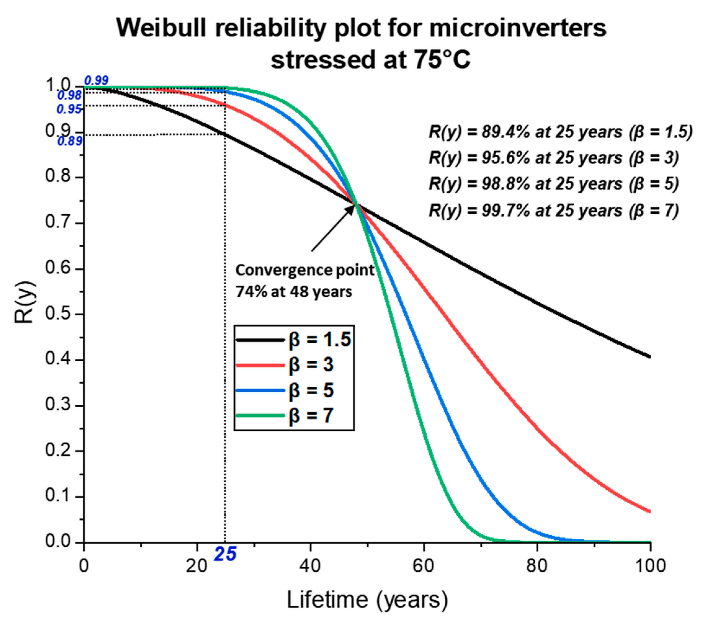
The Weibull survival (reliability) plot with a 95% lower one-sided confidence interval is represented in Figure 8 and Figure 9 for microinverters stressed with fixed and cyclic power profiles at 65 °C and 75 °C, respectively. The microinverter reliability was estimated using Equation (7) with assumed values for the shape factor β . The Weibull reliability plots represents the estimated survival probabilities of the microinverters based on various lifetime ranges (years). Under the fixed and cyclic power profiles at 65 °C, the probability of the microinverters to survive 25 years of field operation is in the range of 67–73%, shown with a dotted line in Figure 8, the 25-year field survival probability of the microinverters is in the range of 89–99.7% for the fixed and cyclic power profiles at 75 °C, illustrated with a dotted line in Figure 9. The probability of the microinverters to survive for 25 years during field operation is also represented in Table 3.
In Figure 8 and Figure 9, the microinverter survival curves converge at 24 years for the test profiles at 65 °C and 48 years for the test profiles at 75 °C, respectively. These lifetimes were translated based on the accelerated stress of 15,000 h, where the higher test temperature of 75 °C corresponds to a higher lifetime due to a higher acceleration factor, as shown in Table 1. At the convergence point, the reliability of the microinverters estimated using Equation (7) with a one-sided lower confidence interval of 95% for both test temperatures is approximately 74%. Before the convergence point, the survival curves with higher β values represent a higher survival probability with low early failures. After converging, the survival curves with higher β values demonstrate a lower survival probability, representing a steeper wear-out phase in the microinverter unit’s lifetime. The reliability of 74% estimated using Equation (7) is similar to the reliability approximated earlier in Section B, using the classical success run approach from Equation (2). However, Equation (2) does not take into account the accelerated stress hours and provides limited information regarding the reliability of the microinverters corresponding to specific confidence levels. Equation (7) estimates the reliability at various lifetimes (years) and provides a detailed reliability curve (Figure 8 andFigure 9) for the microinverters based on the shape factor as well as the accelerated stress hours. Thus, the Weibull analysis with a one-sided lower confidence interval of 95% provides the safe and validated reliability and lifetime of the microinverters that can be used as a reference for future studies and built upon in later experiments. However, this analysis was based on thermal failure mechanisms only, whereas the actual multi-stress field operation may considerably reduce the lifetime of the microinverters estimated in this study.
Furthermore, the Weibull distribution used in our study has limitations. It presumes uniformity among the tested items, which may not hold true if multiple failure modes exist, potentially leading to data inaccuracies. The distribution is sensitive to outliers and risks overfitting to certain data, affecting its future predictive power. It can also have difficulty handling data with several major failure patterns. Comparatively, exponential distribution assumes a constant failure rate. The lognormal distribution, used frequently in reliability studies, portrays a declining failure rate, ideal for systems with early failures. The gamma distribution is versatile, such as Weibull, but with less straightforward parameters. The normal distribution, uncommon in reliability studies, is apt when failures center around a specific age.
To improve the microinverter reliability, a multi-tiered strategy is essential. Improved thermal management is crucial, involving advanced cooling techniques and temperature sensors for real-time monitoring. Component selection is vital, emphasizing high-temperature-rated parts, especially capacitors and semiconductors, sourced from quality-focused manufacturers. Implementing advanced protective mechanisms can detect potential failures and ensure safer operation, with features such as over-temperature protection and voltage controls. A robust design that can handle peak loads without maxing out is key, and enclosing electronics in moisture- and dust-resistant casings is beneficial. Lastly, leveraging field data offer several insights. Encouraging users to share operational data helps to refine design, which can address real-world challenges and enhance reliability.

4. Conclusions

In this study, forty microinverter units were tested at two different high static temperatures and two different input power profiles. The microinverters were stressed at the static temperatures of 65 °C and 75 °C for 15,000 h to estimate their lifetimes and reliability. Although none of the MLPE units showed failure (defined as degradation of more than 5% or device non-functioning), extrapolating the data to a field-use lifetime (for Mesa, Arizona, a hot–dry desert climate) shows that the microinverters should be able to survive 24–48 years in field conditions with a reliability of 74%, having a one-sided lower confidence bound of 95% using the classical success run approach. The cyclic power profile at both test temperatures had no significant effect on the rated output power of the microinverters, but with only two static test temperatures applied in this study, further analysis based on multiple stress temperatures may be required to validate this observation. As no microinverter failures occurred, the Weibull distribution was assumed. This analysis was performed assuming multiple values for the Weibull shape factor, where a range of characteristic lifetime periods was determined along with the estimation of the reliability of the microinverters. With a statistical one-sided lower confidence limit of 95%, the Weibull analysis indicates that the microinverter units can survive the 25-year warranty period without any significant failures. This demonstrates the robustness of MLPE devices that can perform for long lifetimes and could outlive PV modules in field-use operating conditions.
However, the actual field operation with multiple stress factors can induce other failure mechanisms depending on the actual environmental stressors. This study presented only a ceiling for the reliability and lifetime of microinverters with respect to high-static-temperature failure mechanism. There exists a possibility of additional failure mechanisms that could affect the lifetime of microinverter units in actual field conditions and could reduce their operational hours from what was reported in this study. Furthermore, the stress temperatures investigated were specifically limited to conditions such as 65 °C and 75 °C. Such a restricted temperature range might not reflect the diverse thermal challenges that devices encounter across different geographical terrains. The power profiles adopted in this study, both fixed and cyclic, were chosen to mimic typical field scenarios. However, these might not represent the full spectrum of operational conditions, especially considering factors such as varying solar exposure, grid instabilities, or load fluctuations. Finally, our reliance on the Weibull distribution introduces inherent model-associated uncertainties. While these models are undoubtedly informative, the assumptions they are built upon might not always resonate with the dynamic variability observed in actual operational environments.

Author Contributions

Conceptualization, J.F., D.S. and G.T.; Methodology, M.A., S.T., J.F., D.S. and G.T.; Software, M.A., S.T. and D.S.; Validation, M.A. and G.T.; Formal analysis, M.A. and G.T.; Investigation, M.A., S.T. and G.T.; Resources, J.F. and G.T.; Data curation, M.A., S.T. and G.T.; Writing—original draft, M.A. and G.T.; Writing—review & editing, M.A., J.F., D.S. and G.T.; Visualization, M.A. and G.T.; Supervision, M.A., S.T. and G.T.; Project administration, G.T.; Funding acquisition, J.F. and G.T. All authors have read and agreed to the published version of the manuscript.

Funding

This material is based upon work supported by the Department of Energy, Office of Energy Efficiency and Renewable Energy (EERE), under Award Number DE-EE-0000861.

Conflicts of Interest

The authors declare no conflict of interest.

References

  1. Photovoltaic Systems with Module-Level Power Electronics. U.S. Department of Energy. 2015. Available online: https://www.nrel.gov/docs/fy15osti/64876.pdf (accessed on 9 March 2023).
  2. IEA. Solar PV, IEA, Paris. 2022. Available online: https://www.iea.org/reports/solar-pv (accessed on 8 March 2023).
  3. Feldman, D.; Dummit, K.; Zuboy, J.; Heeter, J.; Xu, K.; Margolis, R. Spring 2022 Solar Industry Update. 2022. Available online: https://www.nrel.gov/docs/fy22osti/82854.pdf (accessed on 8 March 2023).
  4. Shaunagh, M.; Siqi, H.; Cormac, G. Module Level Power Electronics. 2022. Available online: https://cdn.ihsmarkit.com/www/pdf/0822/Module-Level-Power-Electronics.pdf (accessed on 9 March 2023).
  5. Module Level Power Electronics (MLPE) Market Growth Analysis and Industry Research Report to 2030|Solar Edge, Enphase, Tigo/SMA. 31 July 2023. Available online: https://www.marketwatch.com/press-release/module-level-power-electronics-mlpe-market-growth-analysis-and-industry-research-report-to-2030-solar-edge-enphase-tigosma-2023-03-08?mod=search_headline (accessed on 9 March 2023).
  6. Afridi, M.; Kumar, A.; ibne Mahmood, F.; Tamizhmani, G. Hotspot testing of glass/backsheet and glass/glass PV modules pre-stressed in extended thermal cycling. Sol. Energy 2023, 249, 467–475. [Google Scholar] [CrossRef]
  7. Afridi, M.A.; Arbab, M.; Bilal, M.; Ullah, H.; Ullah, N. Determining the effect of soiling and dirt particles at various tilt angles of photovoltaic modules. Int. J. Eng. Work. 2017, 4, 143–146. [Google Scholar]
  8. Kumar, A.L.; Alexander, S.A.; Rajendran, M. Power Electronic Converters for Solar Photovoltaic Systems; Academic Press: Cambridge, MA, USA, 2020. [Google Scholar]
  9. Afridi, M.; Kumar, A.; Mahmood, F.I.; TamizhMani, G. Comparative Analysis of Hotspot Stress Endurance in Pristine and Thermal Cycled Prestressed Glass–Glass Photovoltaic Modules. Sustainability 2023, 15, 12131. [Google Scholar] [CrossRef]
  10. Deline, C.; Meydbray, J.; Donovan, M. Photovoltaic Shading Testbed for Module-Level Power Electronics: 2016 Performance Data Update. 2016. Available online: https://www.nrel.gov/docs/fy16osti/62471.pdf (accessed on 9 March 2023).
  11. Deline, C.; Marion, B.; Granata, J.; Gonzalez, S. Performance and Economic Analysis of Distributed Power Electronics in Photovoltaic Systems. 2011. Available online: https://www.nrel.gov/docs/fy11osti/50003.pdf (accessed on 9 March 2023).
  12. ibne Mahmood, F.; Kumar, A.; Afridi, M.; TamizhMani, G. Potential induced degradation in c-Si glass-glass modules after extended damp heat stress. Sol. Energy 2023, 254, 102–111. [Google Scholar] [CrossRef]
  13. Ma, M.; Wang, H.; Xiang, N.; Yun, P.; Wang, H. Fault diagnosis of PID in crystalline silicon photovoltaic modules through IV curve. Microelectron. Reliab. 2021, 126, 114236. [Google Scholar] [CrossRef]
  14. Plante, R.H. Solar Energy, Photovoltaics, and Domestic Hot Water: A Technical and Economic Guide for Project Planners, Builders, and Property Owners; Academic Press: Cambridge, MA, USA, 2014. [Google Scholar]
  15. Dogga, R.; Pathak, M. Recent trends in solar PV inverter topologies. Sol. Energy 2019, 183, 57–73. [Google Scholar] [CrossRef]
  16. Cha, W.-J.; Kwon, J.-M.; Kwon, B.-H. Highly efficient step-up dc–dc converter for photovoltaic micro-inverter. Sol. Energy 2016, 135, 14–21. [Google Scholar] [CrossRef]
  17. Day, N.U.; Reinhart, C.C.; DeBow, S.; Smith, M.K.; Sailor, D.J.; Johansson, E.; Wamser, C.C. Thermal effects of microinverter placement on the performance of silicon photovoltaics. Sol. Energy 2016, 125, 444–452. [Google Scholar] [CrossRef]
  18. Bilal, M.; Arbab, M.N.; Afridi, M.Z.U.A.; Khattak, A. Increasing the output power and efficiency of solar panel by using concentrator photovoltaics (CPV). Int. J. Eng. Work. 2016, 3, 98–102. [Google Scholar]
  19. Parker, T.P.; Chapman, P.L.; Gilchrist, P. Dominant factors affecting reliability of alternating current photovoltaic modules. In Proceedings of the 2015 IEEE 42nd Photovoltaic Specialist Conference (PVSC), New Orleans, LA, USA, 14–19 June 2015; pp. 1–6. [Google Scholar]
  20. De Leon, S.; Calleja, H.; Mina, J. Reliability of photovoltaic systems using seasonal mission profiles and the FIDES methodology. Microelectron. Reliab. 2016, 58, 95–102. [Google Scholar] [CrossRef]
  21. Krauter, S.; Bendfeld, J. Cost, performance, and yield comparison of eight different micro-inverters. In Proceedings of the 2015 IEEE 42nd Photovoltaic Specialist Conference (PVSC), New Orleans, LA, USA, 14–19 June 2015; pp. 1–4. [Google Scholar]
  22. Armijo, K.M.; Yang, B.B.; Riley, D.; Lavrova, O.; Gonzalez, S.; Lomasney, H. Predictive reliability for AC photovoltaic modules based on electro-thermal phenomena. In Proceedings of the IEEE 42nd Photovoltaic Specialist Conference (PVSC), New Orleans, LA, USA, 14–19 June 2015; pp. 1–6. [Google Scholar]
  23. Flicker, J.; Tamizhmani, G.; Moorthy, M.K.; Thiagarajan, R.; Ayyanar, R. Accelerated Testing of Module-Level Power Electronics for Long-Term Reliability. IEEE J. Photovolt. 2017, 7, 259–267. [Google Scholar] [CrossRef]
  24. Afridi, M.; Tatapudi, S.; Flicker, J.; Srinivasan, D.; Tamizhmani, G. Reliability evaluation of DC power optimizers for photovoltaic systems: Accelerated testing at high temperatures with fixed and cyclic power stresses. Eng. Fail. Anal. 2023, 152, 107484. [Google Scholar] [CrossRef]
  25. Lakshminarayanan, V.; Sriraam, N. The effect of temperature on the reliability of electronic components. In Proceedings of the 2014 IEEE International Conference on Electronics, Computing and Communication Technologies (CONECCT), Bangalore, India, 6–7 January 2014; pp. 1–6. [Google Scholar]
  26. Ristow, A.; Begovic, M.; Pregelj, A.; Rohatgi, A. Development of a methodology for improving photovoltaic inverter reliability. IEEE Trans. Ind. Electron. 2008, 7, 2581–2592. [Google Scholar] [CrossRef]
  27. Sastry, A.; Kulasekaran, S.; Flicker, J.; Ayyanar, R.; TamizhMani, G.; Roy, J.; Srinivasan, D.; Tilford, I. Failure modes and effect analysis of module level power electronics. In Proceedings of the 2015 IEEE 42nd Photovoltaic Specialist Conference (PVSC), New Orleans, LA, USA, 14–19 June 2015; pp. 1–3. [Google Scholar]
  28. Luko, S.N.; Neubauer, D.V. Building on Reliability: Reliability Test Planning. ASTM Standardization News, January/February 2021. Available online: https://sn.astm.org/data-points/building-reliability-reliability-test-planning-jf21.html (accessed on 10 July 2023).
  29. Flicker, J. Reliability of Module Level Power Electronics and Standards Development. p. 2015. Available online: https://www.researchgate.net/profile/Jack-Flicker/publication/279448898_Poster_Module_Level_Power_Electronics_Reliability_and_Standards_Development/links/5592f1bf08ae16f493ee495a/Poster-Module-Level-Power-Electronics-Reliability-and-Standards-Development.pdf (accessed on 10 July 2023).
  30. Tatapudi, S.; Flicker, J.; Srinivasan, D.; Upadhyaya, J.; Selvarangan, K.; Nandakumar, L.; Leslie, J.; Tamizhmani, G. Design of Experimental Test Setup for Large-scale Reliability Evaluation of Module Level Power Electronics (MLPE). In Proceedings of the 2018 IEEE 7th World Conference on Photovoltaic Energy Conversion (WCPEC) (A Joint Conference of 45th IEEE PVSC, 28th PVSEC 34th EU PVSEC), Waikoloa, HI, USA, 10–15 June 2018; pp. 1347–1351. [Google Scholar]
  31. Hacke, P.; Clemens, D.; Thiagarajan, R.; Flicker, J.; Igarashi, H. Evaluation of the DC bus link capacitors and power transistor modules in the qualification testing of PV inverters. Prog. Photovolt. Res. Appl. 2021, 29, 675–683. [Google Scholar] [CrossRef]
  32. Flicker, J. Capacitor Reliability in Photovoltaic Inverters. 2015. Available online: https://www.researchgate.net/publication/279448671_Capacitor_Reliability_in_Photovoltaic_Inverters (accessed on 9 March 2023).
  33. Kozak, J.P.; Ngo, K.D.; DeVoto, D.J.; Major, J.J. Impact of accelerated stress-tests on SiC MOSFET precursor parameters. In Proceedings of the International Symposium on 3D Power Electronics Integration and Manufacturing (3D-PEIM), College Park, MD, USA, 25–27 June 2018; pp. 1–5. [Google Scholar]
  34. IEC 62093-2021; Power Conversion Equipment for Photovoltaic Systems—Design Qualification Testing. International Electrotechnical Commission: London, UK, 2021.
  35. Afridi, M.Z.U.A. Module Level Power Electronics and Photovoltaic Modules: Thermal Reliability Evaluation. Doctoral Dissertation, Arizona State University, Tempe, AZ, USA, 2023. [Google Scholar]
  36. Tariq, M.S.; Butt, S.A.; Khan, H.A. Impact of module and inverter failures on the performance of central-, string-, and micro-inverter PV systems. Microelectron. Reliab. 2018, 88, 1042–1046. [Google Scholar] [CrossRef]
  37. Kim, K.-S.; Jeong, S.-G.; Kwon, B.-H. Single power-conversion DAB microinverter with safe commutation and high efficiency for PV power applications. Sol. Energy 2019, 193, 676–683. [Google Scholar] [CrossRef]
  38. Watson, J.; Castro, G. A review of high-temperature electronics technology and applications. J. Mater. Sci. Mater. Electron. 2015, 26, 9226–9235. [Google Scholar] [CrossRef]
  39. Military Handbook: Reliability Prediction of Electronic Equipment; Department of Defense: Washington, DC, USA, 1991.
  40. Flicker, J.; Lavrova, O.; Tamizhmani, G. Co-located Accelerated Testing of Module Level Power Electronics and Associated PV Panels. In Proceedings of the IEEE 7th World Conference on Photovoltaic Energy Conversion (WCPEC), Waikoloa, HI, USA, 10–15 June 2018; pp. 1273–1277. [Google Scholar]
  41. Luko, S.N. Attribute Reliability and the Success Run: A Review. SAE Trans. 1997, 106, 251–261. [Google Scholar] [CrossRef]
  42. Luko, S.N. Weibull Analysis with Assumed Weibull Slope Where NO Failures are Observed. SAE Trans. 1998, 107, 347–352. [Google Scholar] [CrossRef]
  43. Nelson, W. Applied Life Data Analysis; John Wiley & Sons: Hoboken, NJ, USA, 1982. [Google Scholar]
  44. Nelson, W. Weibull analysis of reliability data with few or no failures. J. Qual. Technol. 1985, 17, 140–146. [Google Scholar] [CrossRef]
  45. Luko, S.N.; Neubauer, D.V. Building on Reliability: Reliability Test Planning, Part 2. ASTM Standardization News, May/June 2021. Available online: https://sn.astm.org/data-points/building-reliability-reliability-test-planning-part-2-mj21.html (accessed on 10 July 2023).
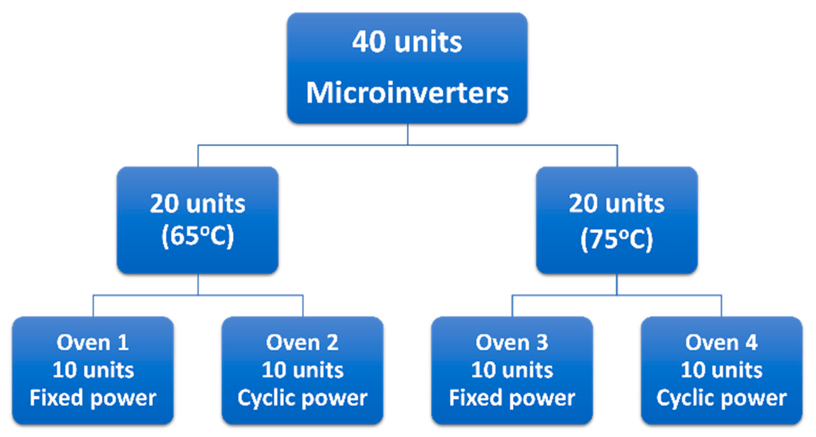
Figure 1. Microinverter design for the experiments.
Energies 16 06511 g001
Figure 2. Cyclic power profile illustration showing power cycling in one cycle.
Energies 16 06511 g002
Figure 3. Microinverter testing setup illustrated in detail.
Energies 16 06511 g003
Figure 4. Block diagram for the microinverters in the testing setup showing typical 1 of 10 units within the dashed lines.
Energies 16 06511 g004
Figure 5. Median output power (median after every 2500 h) of ten microinverters per test profile at the end of the accelerated stress test that operated at the rated (nameplate) output power.
Energies 16 06511 g005
Figure 6. Box plot representing the median efficiency (normalized) of ten microinverters per test profile at the end of the accelerated stress test.
Energies 16 06511 g006
Figure 7. Hourly variation of the acceleration factors during daytime for Mesa, Arizona, for the microinverters at 65 °C and 75 °C.
Energies 16 06511 g007
Figure 8. Weibull reliability plot showing microinverter survival probabilities (with assumed shape factors) for test profiles at 65 °C with a 95% lower one-sided confidence interval.
Energies 16 06511 g008
Figure 9. Weibull reliability plot showing microinverter survival probabilities (with assumed shape factors) for test profiles at 75 °C with a 95% lower one-sided confidence interval.
Energies 16 06511 g009
Table 1. Estimated lifetimes of the microinverters at different static test temperatures.
Microinverters
Testing hours (h)15,000
Temperature65 °C75 °C
Average acceleration factor4.79.4
Equivalent field operational time hours (h) based on 24 h per day MLPE operation70,470
(8 years)
140,500
(16 years)
Equivalent field operational time (years) based on 8 h per day MLPE operation2448
Table 2. Microinverters’ reliability and confidence bounds for N = 10 units and no failures.
Confidence Level (%)Reliability (%)
6091.24
7088.65
8085.13
9079.43
9574.11
9963.09
Table 3. Estimated parameters (95% confidence interval) of the microinverters based on assumed shape factors.
Microinverters at 65 °C (Fixed and Cyclic Power)
Field-equivalent operational time
(years)
24
Shape factor 1.5357
Scale factor (years)53.635.930.528.5
L10 lifetime (years)121719.520.7
L50 (Median) lifetime (years)4231.728.427
25-year survival probability (%)72.771.369.367.1
Microinverters at 75 °C (Fixed and Cyclic Power)
Field-equivalent operational time
(years)
48
Shape factor 1.5357
Scale factor (years)10771.76157
L10 lifetime (years)24343941.4
L50 (Median) lifetime (years)8463.55754
25-year survival probability (%)89.495.998.899.7
Disclaimer/Publisher’s Note: The statements, opinions and data contained in all publications are solely those of the individual author(s) and contributor(s) and not of MDPI and/or the editor(s). MDPI and/or the editor(s) disclaim responsibility for any injury to people or property resulting from any ideas, methods, instructions or products referred to in the content.