Abstract
The precise calculation of phase angle, voltage magnitude and frequency is crucial for the effective control of power electronic inverters connected to an electrical power system. The phase-locked loop (PLL) is a commonly employed method for measuring these variables. Nevertheless, the reliability of this measurement is influenced by transient events in the electrical power system and varies depending on the nature of the event and the specific design of the PLL. Notably, PLLs utilizing the double second-order generalized integrator are widely adopted for power converter synchronization purposes. This article proposes a three-phase PLL, which is based on the single-phase version previously reported by the authors. The proposed PLL, based on an alternative integrator approach, allows a fine adjustment of the tolerance to disturbances in the input voltage thanks to a second feedback gain in its pre-filter. It is reasonable to anticipate that the three-phase PLL will exhibit similar strengths to the single-phase version; however, in the three-phase case, an additional integrator is involved in pre-filtering the quadrature signals, and the double integrator is not employed as the quadrature signal generator. The performance of the proposed PLL is assessed by comparing it to other PLLs based on the second-order integrator, using a processor-in-the-loop approach.
1. Introduction
The interconnection of distributed generation (DG) units based on renewable energy sources to the electrical power system (EPS) is increasing. A critical factor for a successful interconnection is the implementation of effective synchronization algorithms in DG inverters. These algorithms play a crucial role in the operation and stability of the DG inverter that injects power into the grid, even when disturbances occur in the EPS [1,2,3,4,5]. The phase-locked loop (PLL) is a commonly employed method for synchronization. It is crucial to prevent incorrect measurements, instability, and loss of synchronism [6,7,8,9], regardless of reliability issues in the transmission and distribution system, unbalanced voltages and harmonic distortions at the PLL input [2,10]. For instance, since phase-to-ground faults account for up to 95% of the faults in the power system, therefore, the operation of converters with unbalances and distortions in the EPS is a requirement [8,10]. Optimizing the loop filter bandwidth requires carefully considering the trade-off between filtering performance, response time, and stability [2,10,11]. The primary challenge for PLLs is to achieve a swift transient response while maintaining accurate angle tracking, harmonic rejection, and resilience against disturbances in the electrical network. To ensure compliance with IEEE Std 519, for grid, microgrid and grid-connected applications including photovoltaic applications, the currents drawn from the grid must have a total harmonic distortion (THD) of less than 5.0% [12].
Some PLLs, like the moving average filter-based phase-locked loop (MAF-PLL), can accurately obtain network synchronization signals under adverse network conditions with a high amount of harmonics due to the MAF’s high filtering capability. However, the MAF-PLL cannot achieve a fast dynamic response in cases of frequency drift, phase angle jumps or unbalanced voltage sags [13]. Generally, the operation of PLLs is compromised when the network voltage and current contain harmonics as well as during periods when the network experiences faults and disturbances [2,10,14,15,16]. It is important to consider that the grid frequency can exhibit significant fluctuations during transients and faults in power systems with high DG penetration [17,18].
The second-order generalized integrator phase-locked loop (SOGI-PLL) is widely utilized as a synchronization algorithm in various applications related to signal synchronization and the control of power electronics devices. Its popularity stems from its simplicity, low computational cost, and ability to bypass filtering delays [19,20,21]. SOGI-based algorithms are also employed in determining resonant frequencies for proportional resonant controls [22]. In this paper, a modification of the DSOGI-PLL architecture is proposed. The modification aims to enhance the stability of the pre-filter stage for quadrature and signals while increasing the bandwidth of the PLL structure. This results in a fast response of the PLL as a whole without compromising the distinctive harmonic rejection capability of SOGI-based PLLs. The proposed approach involves decoupling the effect of the single SOGI-QSG (quadrature signal generator) gain and introducing a second QSG gain. Additionally, feedback from the bandpass filter output signal is added to the QSG input. The new QSG pre-filter gain allows the manipulation of additional attenuation while improving stability by shifting the QSG poles. The proposed structure is referred to as ARF-DSOGI-PLL, which stands for PLL with Adjustable Re-Filtering based on a Double Second-Order Generalized Integrator. Several tests are carried out under different disturbances in the EPS voltage, particularly frequency deviations, since erroneous frequency measurements can disconnect the inverters of the DG units. Different bandwidths are considered, since the speed of the transient response of the PLL depends on this setting. The magnitudes of the disturbances and the bandwidths were selected to demonstrate the weaknesses and strengths of the algorithms. At the same time, it is shown that the performance of the proposed PLL does not depend on a specific bandwidth nor the type and magnitude of the specific disturbance.
The paper is structured as follows: Section 1 provides an introductory overview of the fundamental aspects of PLLs. Section 2 provides an overview of the ARF-DSOGI implementation; Section 2.1 introduces the proposed modified structure of the DSOGI-QSG, which is referred to as the ARF-DSOGI-QSG and Section 2.2 outlines the criteria for evaluating the performance of the PLL. Section 3 presents a comparison of the responses of the ARF-DSOGI-PLL, DSOGI-PLL with FLL, DSOGI-PLL, SRF-PLL and the Simulink PLL, subjected to frequency deviations, phase jumps, voltage sags and harmonic pollution. The PLLs are evaluated for a typical bandwidth in the loop filter (tuning S1) and also a wide bandwidth (tuning S2). Section 4 provides a comprehensive comparison between two PLLs, namely the ARF-DSOGI-PLL and the DSOGI-PLL-EFI, focusing on their dynamic performance and robustness. The comparison entails a detailed analysis to identify which PLL exhibits superior characteristics in these aspects. In Section 5, the computational resources and execution times of the tested PLLs are also compared. Finally, the conclusions are presented in Section 6.
2. Development of the Improved PLL
In this section, an enhanced DSOGI-PLL is proposed, aiming to achieve several performance improvements. The desirable enhancements are outlined as follows: (a) Faster response without sacrificing the rejection of harmonic content, (b) Reduced transient error in phase tracking, (c) More robustness when subjected to disturbances of greater magnitude without compromising stability, in comparison to other algorithms, and (d) More reliable frequency measurement even in the presence of harmonic contamination, surpassing even the performance of the DSOGI-PLL with FLL.
The ARF-DSOGI-PLL consists of three stages:
- 1.
- A pre-filter for the and quadrature signals obtained from the Clarke transformation. This pre-filter operates in the stationary reference frame and is referred to as a dual second-order generalized integrator with adjustable re-filtering (ARF-DSOGI).
- 2.
- A sequence components calculator. Its utilization is recommended as a way to eliminate the effect of negative sequence components. This part of the algorithm is the same as that used in a DSOGI-PLL.
- 3.
- The loop controller. This is a proportional–integral (PI) controller that also functions as a low-pass filter, which is commonly referred to as a loop filter. It operates in the synchronous reference frame and is responsible for phase angle tracking and the attenuation of high-frequency harmonics.
The transfer function (1) is the basis for obtaining the transfer functions (2) and (3) that describe the bandpass and low-pass filtering actions, respectively. These transfer functions are obtained using the ARF-SOGI shown in Figure 1 [23]. This is a modification of the SOGI-QSG analyzed in [24]. The ARF-DSOGI is implemented using two ARF-SOGI-QSGs.
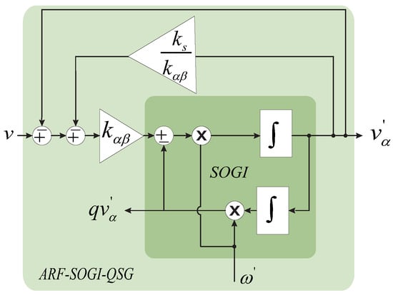
Figure 1.
Architecture of the ARF-SOGI-QSG.
In this context, v represents the input voltage to the PLL, specifically the EPS voltage intended to be sensed by the PLL. denotes the discrepancy between v and the output voltage obtained through the bandpass filter of the ARF-SOGI-QSG. The PLL computes the angular frequency denoted as . The parameter denotes the shared tuning gain for both the SOGI-QSG and the ARF-SOGI-QSG. Additionally, is the additional tuning gain for the extra closed loop that differentiates the ARF-SOGI-QSG from the SOGI-QSG. On the other hand, designates the resulting output voltage through the low-pass filter of the ARF-SOGI-QSG. The criteria for fine tuning the ARF-SOGI-QSG include enhancing its speed and reducing the tendency to overshoot during the transient period.
The step responses shown in Figure 2 correspond to transfer function (2), which defines the behavior of the implicit bandpass filter in the ARF-SOGI compared with the transfer function representing the same filtering effect in the SOGI. Although the behavior of the low-pass filter of the ARF-SOGI is not shown, the effect of the gain is the same, meaning a reduction in overshoot and faster response compared to the SOGI-QSG while improving the stability of the pre-filter. In Figure 2, it can be seen that the ARF-SOGI reduces the overshoot of the pre-filter and achieves shorter stabilization times compared to the original SOGI-QSG. The intention is to incorporate this behavior of the ARF-SOGI into the response of the ARF-DSOGI. The details of obtaining the model and transfer functions of the ARF-SOGI-QSG can be found in [23].
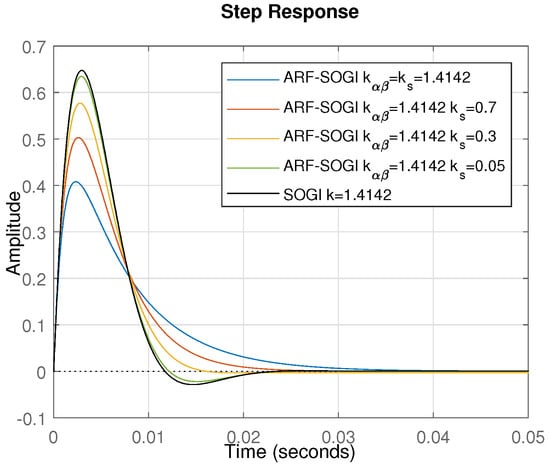
Figure 2.
Step response of ARF-SOGI-QSG bandpass filter.
Figure 3 illustrates the implementation of the ARF-DSOGI pre-filter, consisting of two ARF-SOGI filters similar to those used in DSOGI [5]. The algorithm shown in Figure 3 is thus a modification of the DSOGI presented in [5,24]. The first ARF-SOGI generates the signal, while the second generates the signal, which are then fed into either the Park transformation or the sequence components calculator. Figure 4 depicts the positive and negative sequence calculator (PNSC) [24]. In the implementation of ARF-DSOGI-PLL, it is not necessary to utilize the entire PNSC; only the section responsible for extracting the positive sequence components must be employed, reducing the computational cost of the final implementation.
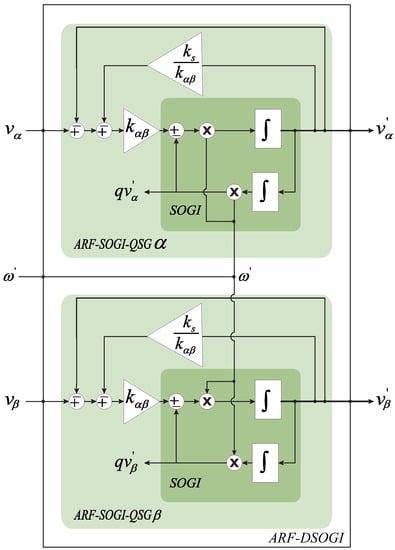
Figure 3.
The ARF-DSOGI filter.
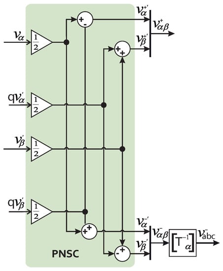
Figure 4.
Positive and negative sequence calculator (PNSC).
2.1. Proposed ARF-DSOGI-PLL Structure
The PLL presented in this article is a modification of the DSOGI-PLL. It is called ARF-DSOGI-PLL and is shown in Figure 5. It comprises three main stages: (1) phase detector, which includes the ARF-DSOGI pre-filter and the sequence component calculator, (2) controller (also referred to as a loop filter) and (3) frequency and phase-angle generator. Figure 5 shows the implementation of the ARF-DSOGI-PLL. It can be seen that the PNSC uses only the positive sequence part.
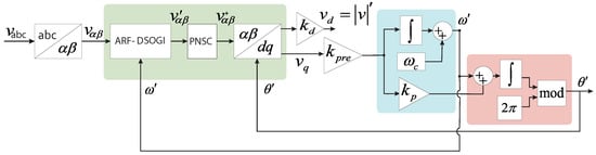
Figure 5.
The complete architecture of the proposed ARF-DSOGI-PLL.
The ARF-DSOGI-PLL is implemented by combining the ARF-DSOGI with a loop filter that includes a gain , preceding the filter or loop controller. The gain compensates for the additional attenuation suffered by the quadrature signals and increases the bandwidth of the loop filter. The PI loop controller, in addition to tracking the angle, filters out high-frequency components in the signals and calculates the frequency using only the integral part of the controller.
2.2. The PLL Performance Evaluation Criteria
The non-linear nature of PLL phase detectors [25] makes it difficult to find PLL performance evaluation criteria when the PLL operation deviates from linearity. However, the criteria for evaluating the performance of PLLs will be assumed as allows.
A THD value of less than 1% is considered acceptable. It is crucial for the unit vectors to be synchronized with the main EPS voltages while ensuring that the harmonic contamination remains below 1% [26,27] because the reference signals for inverter control are derived from the angle calculated by the PLL. When synchronization times are very short, the quality of the unit vectors tends to degrade. Conversely, large frequency deviations, including those permitted by the grid code in electrical power systems, result in longer synchronization times or failed re-synchronization. In both scenarios, the extracted system frequency becomes incorrect during the transient period. Therefore, there is a need to enhance the PLL’s response in two aspects: increasing the speed at which the correct frequency value is reported (while ensuring the degradation of unit vector quality does not exceed 1%) and reducing the error in the reported frequency during the PLL transient [9].
The disconnection times of the converter during voltage variations are specified in standards such as IEEE 1547, IEC61727, and VDE0126-1-1 [24,28,29,30]. Likewise, guidelines for handling frequency deviations and the permissible ranges are outlined in these standards [24,28,29]. According to the IEEE 1547 standard, in the presence of disturbances where the system frequency remains within the range of 58.8 to 61.2 Hz, the converter should remain operational and continue to provide active power. The low-frequency ride-through period extends from 57.0 to 58.8 Hz, lasting for 299 s at most, while the high-frequency ride-through range is 61.2 Hz < f < 61.8 Hz. During these specific ranges and periods, it is crucial that the converter does not trip and maintains the provision of active power. However, if the frequency deviation exceeds 3.5 Hz, the converter will be disconnected after a 0.16 s interval. Hence, it is imperative for a PLL to accurately report frequency deviations of this magnitude within the given 0.16 s time frame to prevent an unintended disconnection.
3. Results: Performance Comparison
In this section, various verification tests are conducted to assess the performance of the ARF-DSOGI-PLL. These tests are carried out using the processor-in-the-loop (PIL) approach [31,32] in MATLAB/Simulink.
3.1. Response to Sintonization 1 (S1)
The gain values for tuning S1 are displayed in Table 1. The values of the gains of the loop filter were calculated as in [33], but in this case, and the loop filter is limited to a PI controller. The value of is chosen according to [24].

Table 1.
Gains for tuning set S1. Typical SOGI bandwidth, typical PLL bandwidth.
In Figure 6, it can be observed that when a frequency deviation of −2.9 Hz occurs, the Simulink PLL takes 249.959 ms to report the correct frequency value with the loop filter tuning suggested by Simulink for optimal performance. This response is the slowest compared to the other PLLs. The synchronization times and the correct frequency measurement of the other PLLs are shown in Table 2. When the loop filter bandwidth is approximately 166 (rad/s), the ARF-DSOGI-PLL algorithm is the fastest to synchronize and accurately measure the frequency without exhibiting overshoot. This provides confidence that transient error in the frequency measurement will not cause the inverter to trigger due to incorrect frequency measurements.
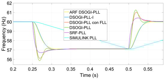
Figure 6.
Frequency measurement by synchronization algorithms under tuning S1.
Table 2.
Times for correct frequency measurement under a deviation of −2.9 Hz and tuning S1.
3.2. Influence of PLLs and Their Tuning on Power Regulation
In this simulation, the inverter is assigned the task of regulating the injected active power to 1000 W and the reactive power to 0 VARs. Figure 7 shows the influence of the synchronization algorithm on power regulation. It can be observed that the SRF-PLL results in the worst performance of the inverter in controlling active power not only in the transient response of the inverter but also in the steady-state response. The SRF-PLL is also reported to have the worst harmonic rejection among the algorithms used, as shown in Table 3.
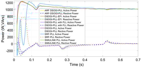
Figure 7.
Active and reactive powers injected by a three-level three-phase inverter in the presence of a −2.9 Hz deviation and under PLLs tuning under S1.
Table 3.
THDs of the unit vector of the PLLs.
The ARF-DSOGI-PLL, besides having a faster transient response, also provides a better regulation of active and reactive powers. The DSOGI-PLL-EFI exhibits the highest overshoot in the reactive power transient response, while active power is regulated almost equally to the other algorithms. The response of DSOGI-PLL and DSOGI-PLL with FLL is similar to that of ARF-DSOGI-PLL. The SRF-PLL synchronizes and measures the frequency adequately in 78.779 ms, but it exhibits the worst harmonic rejection among the algorithms used in this study. Figure 8 shows this, and even though the THD reported in the case of tuning S1 is 0.41%, increasing the bandwidth of the SRF-PLL worsens the rejection of harmonic content. On the other hand, the Simulink PLL demonstrates a better rejection of harmonic content with a THD of only 0.01%. This can be seen in Figure 8. The Simulink PLL has good angle tracking but with higher error compared to ARF-DSOGI-PLL, and it takes much longer to report the correct frequency as shown in Figure 6. Table 3 shows the THDs of the unit vectors for each algorithm tuned with S1.
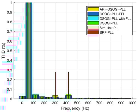
Figure 8.
THD values of the algorithms tuned with S1.
In Figure 9, it can be observed that the DSOGI-PLL with FLL exhibits the worst tracking seven cycles after the −2.9 Hz frequency deviation started, while the rest of the algorithms are already properly locked for S1 tuning.
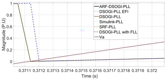
Figure 9.
four cycles after the frequency deviation of −2.9 Hz under tuning S1.
3.3. Wide Bandwidth (S2 Tuning)
For this case, the gain values of the loop controllers are increased to achieve faster transient responses. Table 4 shows the assigned values for the gains in tuning S2. Increasing the bandwidth of the loop controller implies a reduction in the ability to reject harmonic content. These tests aim to demonstrate the functionality of the ARF-DSOGGI-PLL with a larger bandwidth.
Table 4.
Gains for tuning set S2. Large PLL bandwidth.
3.4. Frequency Measurement for a Frequency Deviation of −0.67 Hz in the EPS
In Figure 10, it can be observed how the ARF-DSOGI-PLL and the DSOGI-PLL-EFI exhibit a better transient response in frequency measurement compared to the other PLLs, all with the same wide bandwidth (S2). The frequency deviation, in the form of a step, is −0.67 Hz, starts at t = 0.25 s and ends at t = 0.5 s. It can be seen that during and after the disturbance, all algorithms synchronize except for the Simulink PLL. The SRF-PLL is the first to synchronize with a slight overshoot; however, it also has a low harmonic content rejection capability. On the other hand, the DSOGI-PLL exhibits a transient measurement with significant error due to oscillations. Thus, only three algorithms demonstrate the ability to tolerate wide bandwidths in their loop filter. Table 5 presents the timing of each tested synchronization algorithm in this study under S2 tuning. The Simulink PLL no longer provides accurate frequency measurements; therefore, it is not reported.
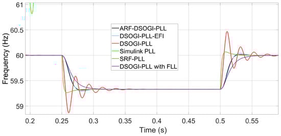
Figure 10.
Transient response in frequency measurement of PLLs for a frequency deviation of −0.67 Hz.
Table 5.
Times when accurate frequency measurements are achieved under S2 tuning.
3.5. Harmonic Content Rejection with High Bandwidth
The SRF-PLL with a large bandwidth (tuning S2) has the shortest measurement time for accurately determining the frequency compared to all other PLLs. However, it also exhibits the poorest rejection of harmonic content, as evidenced by Figure 8 and Figure 11, where the THD in the unit vectors exceeds the permissible level of 1%.
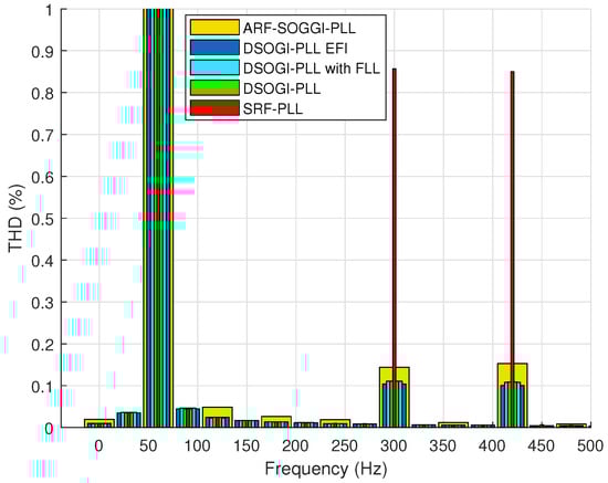
Figure 11.
THD of the unit vectors of each PLL with S2 tuning.
Table 6 shows the THDs of each PLL with tuning S2 and a 4.99% THD in the input voltage. The THDs of the unit vectors corresponding to the Simulink PLL are not shown because, with S2 tuning, the Simulink PLL no longer synchronizes, meaning it no longer accurately calculates the angle. The ARF-DSOGI-PLL reports a THD of 0.22% in its unit vectors, while the DSOGI-PLL with FLL reports a THD of 0.17% in its unit vectors.
Table 6.
THDs of the unit vectors of the PLLs with large bandwidth S2.
3.6. with S2 Tuning
Figure 12 indicates that the Simulink PLL is no longer able to follow the phase angle with a wide bandwidth in the loop filter and that the SRF-PLL algorithm reports the highest error in phase angle tracking, while the other algorithms exhibit a lower error. The rest of the PLL algorithms already exhibit complete synchronization, as shown in Figure 13.
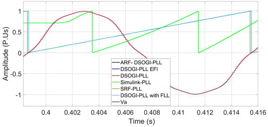
Figure 12.
after the deviation of −0.67 Hz in the EPS. The black, blue and red lines are hidden by the cyan line.
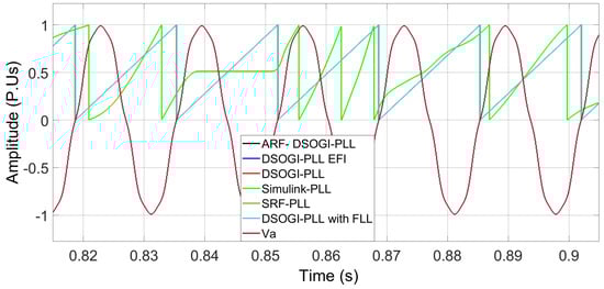
Figure 13.
calculated by the PLLs after recovery from the −0.67 Hz deviation. Some signals are hidden by the cyan line.
3.7. Frequency Measurement with S1 Tuning and a 4.99% THD in the Input Voltage
With a wide band tuning like S2, frequency measurement oscillations are expected due to degradation in the quality of the unit vectors of each PLL. A smooth behavior in frequency measurement is desired, and therefore, bandwidth S1 in the control loops of the PLLs is preferred for EPS synchronization applications. To show the measurements of each algorithm under harmonic contamination of THD = 4.99%, the S1 tuning is chosen. Figure 14 shows the frequency measurement performed by the PLLs in this case when applying a step frequency deviation in the EPS.
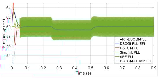
Figure 14.
Frequency measurement when the input voltage has a THD of 4.99% and with S1 tuning in PLLs.
The ARF-DSOGI-PLL with S1 bandwidth reports a reliable frequency measurement even under harmonic contamination in the grid voltage. The measured frequency in the steady-state response of the ARF-DSOGI-PLL varies from 59.99 to 60.01 Hz, which is within the stability band of ±20 mHz suggested in [34]. The DSOGI-PLL-EFI is more reliable than the ARF-SOGI-PLL in frequency measurement under the mentioned harmonic contamination conditions, as its measurement does not oscillate. On the other hand, the DSOGI-PLL reports frequency measurement oscillations ranging from 59.77 to 60.22 Hz, exceeding the maximum recommended deviation of 20 mHz in frequency measurement. The Simulink PLL achieves a frequency measurement of the grid voltage with sporadic variations ranging from 59.99 to 60 Hz. The frequency measurement of the SRF-PLL oscillates from 57.93 to 61.95 Hz.
In [35], some advantages of the DSOGI-PLL with FLL are reported compared to the DSOGI-PLL. However, in frequency measurement under harmonic content, this combination of PLL with FLL also exhibits oscillations ranging from 59.98 to 60.07 Hz, which exceeds the recommended 20 mHz limit. These oscillations outside the maximum deviation band are not advisable for inverter control in the synchronous reference frame or in the static reference frame. For the PLLs that exhibit these oscillations in frequency measurement to be more reliable, the bandwidth of their loop filters needs to be reduced. However, this will result in a slower transient response. A low-pass filter can be added at the output of the frequency calculation stage to reduce these oscillations, but this adds computational cost and each PLL would require a specific tuning for such a filter. Based on the findings in this section, the synchronization algorithms will be tested with a low bandwidth specific to each PLL, aiming to improve their rejection of harmonic content so that their unit vectors report a THD < 1%.
3.8. Response of the PLLs with Reduced Bandwidth, under Low Harmonic Content
Given that in the frequency measurement, the SRF-PLL, DSOGI-PLL, and DSOGI-PLL with FLL exceed the maximum deviation band of 20 mHz despite using the S1 tuning, the option is to reduce the bandwidth to mitigate the oscillations in steady-state frequency measurement. For this test, the gains of each PLL are adjusted such that the frequency measurement performed by each algorithm falls within a maximum deviation band of ±20 mHz. The EPS voltage contains a THD of 4.99%, lower than the 5% indicated in [36], and it is represented by 0.04 and 0.0295 p.u. for the fifth and seventh harmonics, respectively. The results are described below.
The DSOGI-PLL with FLL without harmonic content reports the correct frequency measurement in 61.588 ms, which is faster than the other SOGI-based PLLs. However, the drawback is that it exhibits oscillations in its frequency measurement when there is harmonic content in the input voltage. This is despite being tuned with a low bandwidth of approximately 1.59314 Hz or 10.0097 rad/s in the loop filter. The oscillations in its frequency measurement range from 60.08 to 59.94 Hz, which also exceeds the ±20 mHz band. To ensure that the frequency measurement of the DSOGI-PLL with FLL falls within the ±20 mHz band, the FLL gain must be reduced to = −8 and the DSOGI pre-filter gain to k = 1. The bandwidth of the loop filter remains at 1.59314 Hz, given by = 11.4881 and = 11.6575. With these adjustments, the correct frequency measurement is achieved within a stability band of ±20 mHz. However, the cost is a slower transient response of 130.5 ms. Under these gain changes, when there is no harmonic content in the input voltage, the measurement time is 151.561 ms.
For the oscillations in the frequency measurement of the SRF-PLL to be within the ±20 mHz maximum deviation band, theoretically, it should suffice to drastically reduce the bandwidth [2,24,37]. However, it is implicit in this algorithm that as the bandwidth is drastically reduced, the algorithm will inevitably lose synchronization in the case of even a slight frequency deviation. which may lead to a violation of the standards [28,29] or the grid code [38]. This is evident in Figure 15 and Figure 16.
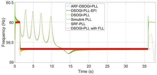
Figure 15.
Frequency measurement with low bandwidth and a THD = 4.99% when a frequency deviation of −0.67 Hz occurs in the EPS. Some signals are hidden by the red line.
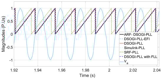
Figure 16.
Angle tracking with low bandwidth and THD = 4.99% when a frequency deviation of −0.67 Hz occurs in the EPS.
The time it takes for the SRF-PLL to report the correct frequency value within the mentioned stability band is approximately 26.726 s. This is achieved by reducing the bandwidth to approximately 2.191 (rad/s) given by the gains = 2.1809 and = 0.42117. This reduction in bandwidth causes the PLL to lose synchronization for a long time and then re-lock and report the correct frequency value. This can be seen in Figure 15. It is clear that for more than 15 s after the disturbance started, the frequency calculation performed by the SRF-PLL is far from the real value. This is due to the loss of synchronization of the PLL after the frequency deviation started, as seen in Figure 16.
4. Final Comparison
This section presents a comparison solely among the PLLs that exhibited better performance in frequency measurement, phase angle tracking under permissible harmonic content conditions, and considering the stability demonstrated during the previous tests. For a voltage sag of 20% of the nominal value, the ARF-DSOGI-PLL takes 0.048 s to accurately report the frequency after the disturbance occurs. After this time, if the voltage dip persists, this PLL continues to correctly report the frequency. On the other hand, the DSOGI-PLL-EFI takes 0.057 s, which is slightly longer than the ARF-DSOGI-PLL. However, it exhibits a lower steady-state error, as can be seen in Figure 17. Figure 18 shows the frequency measured by the ARF-DSOGI-PLL and the DSOGI-PLL-EFI during a voltage sag that reduces the line voltage to only 20% of the nominal value. In this case, the ARF-DSOGI-PLL takes 162.5663 s to report the frequency within a maximum deviation range of 20 mHz, while the DSOGI-PLL-EFI takes 272.598 s.
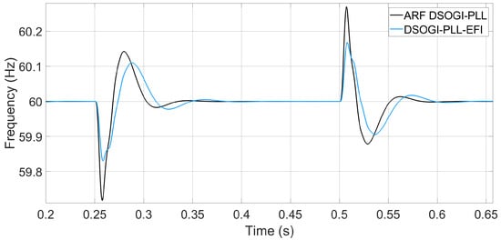
Figure 17.
Frequency measurement for a 20% voltage sag from the nominal voltage of the electrical grid.
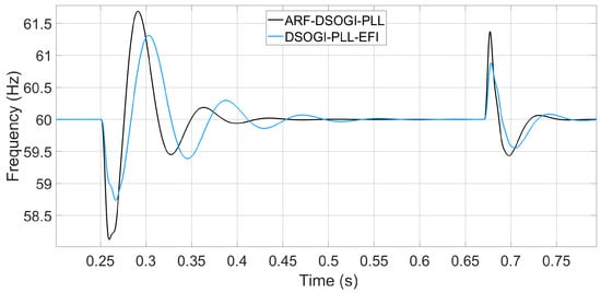
Figure 18.
Frequency measurement for an 80% voltage sag from the nominal voltage of the electrical grid.
Now, the algorithms are tested against a frequency deviation of −0.67 Hz. For these tests, not only are the tuning parameters of the PLL loop filters changed but also the tuning of the ARF-DSOGI and DSOGI pre-filters. The intention behind this is to assess the operational differences between the two algorithms. Figure 19 shows the frequency measurements of the PLLs when a step-like frequency deviation of 0.67 Hz occurs in the EPS voltage. The ARF-DSOGI-PLL and DSOGI-PLL-EFI algorithms report measurement times of 46.808 ms and 88.808 ms, respectively. These measurements fall within a maximum steady-state error band of 20 mHz.
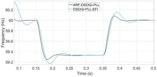
Figure 19.
Frequency measurement for a deviation of −0.67 Hz in the EPS voltage.
The algorithms are next subjected to a phase jump of 72 degrees, and angle tracking and frequency measurement are verified. Figure 20 shows the angle tracked by the algorithms when the phase jump occurs. It can be observed that from the start of the disturbance at t = 15 s, the ARF-DSOGI-PLL better tracks the phase angle. The ARF-DSOGI-PLL synchronizes within the third cycle after the phase jump, while the DSOGI-PLL-EFI appears to synchronize within the fourth cycle. In Figure 21, it can be observed that in the following cycle, the DSOGI-PLL-EFI loses synchronization while the ARF-DSOGI-PLL remains locked. The ARF-DSOGI-PLL achieves synchronization within the third cycle after the phase jump, while the DSOGI-PLL-EFI achieves synchronization within the fifth cycle. In Figure 22, it can be observed that the effect of the reference angle calculated by the ARF-DSOGI-PLL on power injection is the reduction in transient oscillations in the power injected by the grid-following inverter to the power system during the phase jump. It is also observed that power regulation, especially reactive power, is achieved in less time compared to power injection using the same inverter with the DSOGI-PLL-EFI synchronization algorithm.
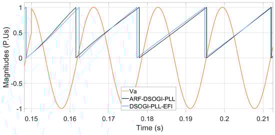
Figure 20.
synchronization process for a phase jump of 72 degrees.
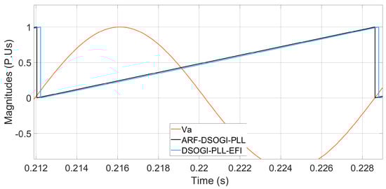
Figure 21.
Details in the synchronization process during a phase jump of 72 degrees.
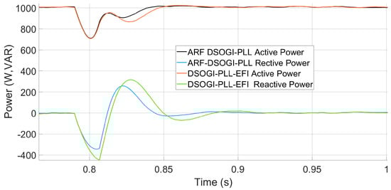
Figure 22.
Active and reactive power for a 72 degree phase jump in the voltage of the electrical grid.
5. Resources and Computing Times
The metrics presented in Table 7 were obtained using a processor-in-the-loop methodology. These metrics include the processing time required by each algorithm for a single cycle of the fundamental frequency as well as the memory usage in the DSC F28335 processor (which has 262 KB available). Upon examination of Table 7, it can be observed that the flash memory requirements for the ARF-DSOGI-PLL and DSOGI-PLL-EFI algorithms are comparable with slightly higher demands for the ARF-DSOGI-PLL. It can be concluded that the increase in memory requirements for the ARF-DSOGI-PLL implementation, in comparison to existing versions of the SOGI-PLL, is not a significant factor for real-world implementations. Furthermore, Table 7 demonstrates that the DSOGI-PLL-EFI algorithm is processed slightly faster than the ARF-DSOGI-PLL.
Table 7.
Memory and processing time required by each algorithm in the DSC.
6. Conclusions
This paper presents a modified PLL algorithm called ARF-DSOGI-PLL. The proposed ARF-DSOGI-PLL incorporates a second gain in the pre-filter stage; also, a feedback loop is added from the output of the bandpass filters to the input of the modified pre-filter. These modifications provide the ability to select additional attenuation in the pre-filter while shifting the pre-filter poles to the left, resulting in improved stability and speed compared to the standard DSOGI-PLL. The enhanced stability achieved by the ARF-DSOGI pre-filter permits increasing the control loop filter bandwidth. As a result, the ARF-DSOGI-PLL provides an improved response speed while upholding harmonic rejection, stability, and processing capability. Furthermore, it reduces frequency measurement overshoot, leading to shorter transient frequency measurement periods. This, in turn, lowers the risk of grid-following inverters halting power injection due to inaccurate frequency measurements. The performance of the ARF-DSOGI-PLL was assessed by subjecting it to various disturbances, including frequency deviations, phase shifts, voltage sags, and harmonics. Its response was compared with three alternative DSOGI-PLL versions using different loop filter settings. Additionally, a comprehensive exploration was conducted regarding three-phase inverter synchronization with the electrical network. The simulations indicate that the new ARF-DSOGI pre-filter-based PLL exhibits improved stability, faster transient response, and sustained harmonic content rejection.
Author Contributions
Conceptualization, G.A.H.-P. and E.M.-V.; methodology, G.A.H.-P. and J.L.M.-M.; software, G.A.H.-P.; validation, J.L.M.-M.; formal analysis, G.A.H.-P., E.M.-V. and J.L.M.-M.; investigation, G.A.H.-P.; resources, E.M.-V.; data curation, G.A.H.-P.; writing—original draft preparation, G.A.H.-P. and E.M.-V.; writing—review and editing, G.A.H.-P., E.M.-V. and J.L.M.-M.; visualization, G.A.H.-P.; supervision, E.M.-V.; project administration, E.M.-V.; funding acquisition, E.M.-V. All authors have read and agreed to the published version of the manuscript.
Funding
This research received no external funding.
Data Availability Statement
Not applicable.
Conflicts of Interest
The authors declare no conflict of interest.
Abbreviations
The following abbreviations are used in this manuscript:
| ARF | Adjustable re-filtering |
| DG | Distributed generation |
| EPS | Electrical power system |
| PLL | Phase-locked loop |
| QSG | Quadrature signal generator |
| SOGI | Second-order generalized integrator |
| DSOGI | Double second-order generalized integrator (DSOGI) |
| THD | Total harmonic distortion |
References
- Best, R.E. Phase-Locked Loops: Design, Simulation, and Applications, 5th ed.; McGraw-Hill: New York, NY, USA, 2003. [Google Scholar]
- Timbus, A.; Liserre, M.; Teodorescu, R.; Blaabjerg, F. Synchronization methods for three phase distributed power generation systems—An overview and evaluation. In Proceedings of the 2005 IEEE 36th Power Electronics Specialists Conference, Recife, Brazil, 12–16 June 2005; pp. 2474–2481. [Google Scholar]
- Best, R.E. Phase-Locked Loops: Design, Simulation, and Applications, 6th ed.; McGraw-Hill Education: New York, NY, USA, 2007. [Google Scholar]
- Yazdani, A.; Iravani, R. Voltage-Sourced Converters in Power Systems: Modeling, Control, and Applications; John Wiley & Sons: Hoboken, NJ, USA, 2010. [Google Scholar]
- Golestan, S.; Guerrero, J.M.; Vasquez, J.C. Three-Phase PLLs: A Review of Recent Advances. IEEE Trans. Power Electron. 2017, 32, 1894–1907. [Google Scholar] [CrossRef]
- Luhtala, R.; Alenius, H.; Roinila, T. Practical Implementation of Adaptive SRF-PLL for Three-Phase Inverters Based on Sensitivity Function and Real-Time Grid-Impedance Measurements. Energies 2020, 13, 1173. [Google Scholar] [CrossRef]
- Golestan, S.; Ramezani, M.; Guerrero, J.M. An Analysis of the PLLs With Secondary Control Path. IEEE Trans. Ind. Electron. 2014, 61, 4824–4828. [Google Scholar] [CrossRef]
- Cao, Y.; Yu, J.; Xu, Y.; Li, Y.; Yu, J. An Efficient Phase-Locked Loop for Distorted Three-Phase Systems. Energies 2017, 10, 280. [Google Scholar] [CrossRef]
- Aldbaiat, B.; Nour, M.; Radwan, E.; Awada, E. Grid-Connected PV System with Reactive Power Management and an Optimized SRF-PLL Using Genetic Algorithm. Energies 2022, 15, 2177. [Google Scholar] [CrossRef]
- Mahdian, H.; Hashemi, M.; Ghadimi, A.A. Improvement in the synchronization process of the voltage-sourced converters connected to the Grid by PLL in order to Detect and Block the Double Frequency Disturbance Term. Indian J. Sci. Technol. 2013, 6, 4940–4952. [Google Scholar] [CrossRef]
- Arricibita, D.; Marroyo, L.; Barrios, E.L. Simple and robust PLL algorithm for accurate phase tracking under grid disturbances. In Proceedings of the 2017 IEEE 18th Workshop on Control and Modeling for Power Electronics (COMPEL), Stanford, CA, USA, 9–12 July 2017; pp. 1–6. [Google Scholar]
- Dartawan, K.; Najafabadi, M. Case study: Applying IEEE Std. 519-2014 for harmonic distortion analysis of a 180 MW solar farm. In Proceedings of the 2017 IEEE Power & Energy Society General Meeting, Chicago, IL, USA, 16–20 July 2017; pp. 1–5. [Google Scholar]
- Ke, S.; Li, Y. Grid-Connected Phase-Locked Loop Technology Based on a Cascade Second-Order IIR Filter. Energies 2023, 16, 3967. [Google Scholar] [CrossRef]
- Rodríguez, P.; Teodorescu, R.; Candela, I.; Timbus, A.V.; Liserre, M.; Blaabjerg, F. New positive-sequence voltage detector for grid synchronization of power converters under faulty grid conditions. In Proceedings of the 2006 37th IEEE Power Electronics Specialists Conference, Jeju, Republic of Korea, 18–22 June 2006; pp. 1–7. [Google Scholar]
- Chung, S.K. Phase-locked loop for grid-connected three-phase power conversion systems. IEE Proc.-Electr. Power Appl. 2000, 147, 213–219. [Google Scholar] [CrossRef]
- Gao, S.; Barnes, M. Phase-locked loop for AC systems: Analyses and comparisons. In Proceedings of the 6th IET International Conference on Power Electronics, Machines and Drives (PEMD 2012), Bristol, UK, 27–29 March 2012; pp. 1–6. [Google Scholar]
- Jauch, C.; Matevosyan, J.; Ackermann, T.; Bolik, S. International comparison of requirements for connection of wind turbines to power systems. Wind Energy 2005, 8, 295–306. [Google Scholar] [CrossRef]
- Bimarta, R.; Tran, T.V.; Kim, K.-H. Frequency-Adaptive Current Controller Design Based on LQR State Feedback Control for a Grid-Connected Inverter under Distorted Grid. Energies 2018, 11, 2674. [Google Scholar] [CrossRef]
- Ciobotaru, M.; Teodorescu, R.; Blaabjerg, F. A new single-phase PLL structure based on second order generalized integrator. In Proceedings of the 2006 37th IEEE Power Electronics Specialists Conference, Jeju, Republic of Korea, 18–22 June 2006; pp. 1–6. [Google Scholar]
- Ciobotaru, M.; Agelidis, V.G.; Teodorescu, R.; Blaabjerg, F. Accurate and Less-Disturbing Active Antiislanding Method Based on PLL for Grid-Connected Converters. IEEE Trans. Power Electron. 2010, 25, 1576–1584. [Google Scholar] [CrossRef]
- Guerrero-Rodríguez, N.; Rey-Boué, A.B.; Bueno, E.; Ortiz, O.; Reyes-Archundia, E. Synchronization algorithms for grid-connected renewable systems: Overview, tests and comparative analysis. Renew. Sustain. Energy Rev. 2017, 75, 629–643. [Google Scholar] [CrossRef]
- Li, X.; Balog, R.S. PLL-less robust active and reactive power controller for single phase grid-connected inverter with LCL filter. In Proceedings of the 2015 IEEE Applied Power Electronics Conference and Exposition (APEC), Charlotte, NC, USA, 15–19 March 2015; pp. 2154–2159. [Google Scholar]
- Herrejón-Pintor, G.A.; Melgoza-Vázquez, E.; Chávez, J.d.J. A Modified SOGI-PLL with Adjustable Refiltering for Improved Stability and Reduced Response Time. Energies 2022, 15, 4253. [Google Scholar] [CrossRef]
- Teodorescu, R.; Liserre, M.; Rodriguez, P. Grid Converters for Photovoltaic and Wind Power Systems; John Wiley & Sons: New Delhi, India, 2011. [Google Scholar]
- Leonov, G.A.; Kuznetsov, N.V.; Yuldashev, M.V.; Yuldashev, R.V. Hold-In, Pull-In, and Lock-In Ranges of PLL Circuits: Rigorous Mathematical Definitions and Limitations of Classical Theory. IEEE Trans. Circuits Syst. I Regul. Papers. 2015, 62, 2454–2464. [Google Scholar] [CrossRef]
- Kulkarni, A.; John, V. Design of a fast response time single-phase PLL with DC offset rejection capability. Electr. Power Syst. Res. 2017, 145, 35–43. [Google Scholar] [CrossRef]
- Kulkarni, A.; John, V. Analysis of Bandwidth–Unit-Vector-Distortion Tradeoff in PLL During Abnormal Grid Conditions. IEEE Trans. Ind. Electron. 2013, 60, 5820–5829. [Google Scholar] [CrossRef]
- IEEE Std 1547a-2020 (Amendment to IEEE Std 1547-2018); IEEE Standard for Interconnection and Interoperability of Distributed Energy Resources with Associated Electric Power Systems Interfaces—Amendment 1: To Provide More Flexibility for Adoption of Abnormal Operating Performance Category III. IEEE: Piscataway, NJ, USA, 2020; pp. 1–16.
- IEC61727; Photovoltaic (PV) Systems-Characteristics of the Utility Interface. International Electrotechnical Commission: Geneva, Switzerland, 2004.
- VDE 0126-1-1; Automatic Disconnection Device between a Generator and the Public Low-Voltage Grid. VDE Verlag GmbH: Berlin, Germany, 1999.
- Motahhir, S.; Ghzizal, A.E.; Sebti, S.; Derouich, A. MIL and SIL and PIL tests for MPPT algorithm. Cogent Eng. 2017, 4, 1378475. [Google Scholar] [CrossRef]
- Krishna Srinivasan, M.; Daya John Lionel, F.; Subramaniam, U.; Blaabjerg, F.; Madurai Elavarasan, R.; Shafiullah, G.M.; Khan, I.; Padmanaban, S. Real-Time Processor-in-Loop Investigation of a Modified Non-Linear State Observer Using Sliding Modes for Speed Sensorless Induction Motor Drive in Electric Vehicles. Energies 2020, 13, 4212. [Google Scholar] [CrossRef]
- Bany Issa, M.A.; Al Muala, Z.A.; Bello Bugallo, P.M. Grid-Connected Renewable Energy Sources: A New Approach for Phase-Locked Loop with DC-Offset Removal. Sustainability 2023, 15, 9550. [Google Scholar] [CrossRef]
- Karimi Ghartemani, M.; Khajehoddin, S.A.; Jain, P.K.; Bakhshai, A. Problems of Startup and Phase Jumps in PLL Systems. IEEE Trans. Power Electron. 2012, 27, 1830–1838. [Google Scholar] [CrossRef]
- Herrejón-Pintor, G.A.; Melgoza-Vázquez, E. DSOGI-PLL with FLL to Mitigate Transient Oscillations in the Frequency and Phase Angle Measurement. In Proceedings of the ROPEC 2022–2022 IEEE International Autumn Meeting on Power, Electronics and Computing (ROPEC), Ixtapa, Mexico, 9–11 November 2022; pp. 1–7. [Google Scholar]
- Kennedy, B.W. Power Quality Primer; McGraw-Hill Education: New York, NY, USA, 2000; pp. 154–196. [Google Scholar]
- Chung, S.K. A Phase Tracking System for Three phase Utility Interface Inverters. IEEE Trans. Power Electron. 2000, 15, 431–438. [Google Scholar] [CrossRef]
- Comisión Reguladora de Energía. Código de Red—Resolución Núm. RES/550/2021; Diario Oficial de la Feredación: Ciudad de México, Mexico, 2021. [Google Scholar]
Disclaimer/Publisher’s Note: The statements, opinions and data contained in all publications are solely those of the individual author(s) and contributor(s) and not of MDPI and/or the editor(s). MDPI and/or the editor(s) disclaim responsibility for any injury to people or property resulting from any ideas, methods, instructions or products referred to in the content. |
© 2023 by the authors. Licensee MDPI, Basel, Switzerland. This article is an open access article distributed under the terms and conditions of the Creative Commons Attribution (CC BY) license (https://creativecommons.org/licenses/by/4.0/).