Review

Review of Hydro-Pneumatic Accumulator Models for the Study of the Energy Efficiency of Hydraulic Systems

Faculty of Mechatronics and Mechanical Engineering, Kielce University of Technology, al. Tysiaclecia Panstwa Polskiego 7, 25-314 Kielce, Poland
*
Author to whom correspondence should be addressed.
Energies 2023, 16(18), 6472; https://doi.org/10.3390/en16186472
Submission received: 25 July 2023 / Revised: 3 September 2023 / Accepted: 5 September 2023 / Published: 7 September 2023
(This article belongs to the Section K: State-of-the-Art Energy Related Technologies)

Abstract

:
This review article deals with hydro-pneumatic accumulators (HPAs) charged with nitrogen. The focus is on HPA models used in the study of the energy efficiency of hydraulic systems. Hydraulic circuits with HPA are presented along with their various applications for delivering the required volume of fluid, maintaining the required pressure, ensuring safe operation, safety stop, leak compensation, fluid volume change compensation, pulsation damping, and pressure shock absorption. A general regenerative hydraulic system and a general hybrid hydraulic system are also presented. The review focuses primarily on HPA computational, dynamic, and simulation models. Basic HPA calculation parameters and computational models of energy storage and thermodynamic cycle are presented. Various computational and dynamic models of HPA have been defined, such as the thermodynamic model, simulation model, dynamic model, pulsation damper model, and shock pulse damper model. Research projects that have used HPA in industrial hydraulic systems are reviewed, such as those maintaining operating pressure in an industrial 80 MN open-die hydraulic forging press and acting as a shock pulse absorber in the lifting and levelling module of a tracked mobile robotic bricklaying system. The development of energy storage technology in HPA from various sources is now a global challenge.

1. Introduction

To achieve the 2030 climate target, the European Commission (EC) presented a proposal in July 2021 from the European Parliament (EP) and the European Council (EC) for an Energy Efficiency Directive (EED) as part of the package “Delivering the European Green Deal (EGD)” [1]. With the EGD, the European Union (EU) is increasing its climate ambitions and aims to become the first climate-neutral continent by 2050. To implement this, the EC Work Programme announced a ‘Fit for 55′ package to reduce greenhouse gas (GHG) emissions by at least 55% by 2030 and achieve a climate neutral Europe by 2050. This package will cover a wide range of policy areas, including energy efficiency and renewables. Energy efficiency is a key area of action that can lead to the complete decarbonisation of the EU economy. Greater solidarity with climate neutrality should be synonymous with the EGD [2]. The EGD will initiate a new substantive approach to environmental and climate issues at the political, institutional, regulatory, administrative, and individual levels.
A new RE ecodesign for electric motors and variable-speed drives, including hydraulic pumps, has been launched, with the aim of improving the energy efficiency of these products in the EU [3]. Ecodesign sets common EU-wide minimum standards to eliminate the worst-performing products from the market. Worldwide, electric motors account for around 50% of electricity consumption. The EU supports the Super-Efficient Equipment and Appliances Deployment (SEAD) initiative, which brings together countries around the world to cooperate in the promotion of efficient appliances [4]. The SEAD focuses on electric motors, among others, and has set the goal of doubling the efficiency of electric motor-powered products sold worldwide by 2030, which was welcomed by the G7 ministers. Electricity production is the main source of GHG emissions, accounting for 41% of energy-related CO2 emissions. Electricity demand will continue to grow rapidly and will increase by 60% globally by 2040 based on today’s political ambitions. Energy efficiency is the single most important measure to reduce GHG emissions to achieve the objectives of the Paris Agreement. The EC has developed a plan to allow the sale of new cars with internal combustion engines (ICE) in 2035 if these only run on climate-neutral e-fuels.
Electric motors used in industrial machines and devices, as well as ICE used in vehicles, mobile machines, and marine devices, participate in the transformation of mechanical power into hydraulic power. In power transmission, hydraulic drive systems have a high power density. Hydraulic pumps, as energy sources in hydraulic drive systems, are widely used due to their high working pressure and high flow rate. Hydraulic pumps account for the largest share of sales of hydraulic products and are expected to reach 36 million units around the world in 2023 [5]. Heavy-duty machinery manufacturers face global competition and stringent environmental regulations that require more energy-efficient technology. The hydraulic machinery sector is responsible for more than a third of global energy consumption and almost 40% of total direct and indirect CO2 emissions [6]. Furthermore, hydraulic systems consume large amounts of harmful hydraulic fluids. The oil leakage from hydraulic equipment is estimated to be 370 million litres per year [7]. The introduction of energy-efficient solutions contributes to the achievement of the EU’s climate action goals, along with the European Green Deal, the Energy Efficiency Directive, and health and safety directives. Energy-efficient solutions are in accordance with the EU regulation on the requirements for the limits of GHG emissions and particulate pollutants and the approval of hydraulic mobile machines.
The energy efficiency of technical devices is the main element of the energy policy of many countries. The main impediment to the optimal implementation of the energy savings programs is the lack of data to establish market benchmarks, assess cost-effective energy savings, and track markets. The International Effective Devices Database (IDEA) was developed as a software toolkit that automatically collects data scattered across various online sources and compiles them into a unified repository of performance, price, and feature information for devices in markets around the world [8]. In recent years, the development of hydraulic drive systems has focused on energy efficiency. Optimising losses and increasing the energy efficiency of hydraulic drive systems involves reducing energy losses by minimising all hydraulic and mechanical losses. When designing hydraulic drive systems, the achievement of minimising potential losses results from the concept of the control system and the selection of components for a specific task. There exists a great potential to increase the energy efficiency of hydraulic drive systems by reducing losses and thus minimising energy consumption. The improvement of energy efficiency in hydraulic systems is achieved by reducing volumetric, hydraulic and mechanical losses, avoiding losses related to flow throttling, and recovering potential and kinetic energy from drive units [9]. In hydraulic systems, various methods to improve energy efficiency are used, consisting of effective control, reduction in energy losses, energy regeneration, and the hybridisation of the drive [10]. Energy-saving hydraulic systems are obtained thanks to the new direct driven hydraulic (DDH), controlled electric motors, and electronic control systems [11,12,13,14,15,16]. With the wide use of hydraulically driven machinery, especially high–powered hydraulic mobile machinery, there is great interest in research on energy-saving measures and strategies due to energy costs, environmental regulations, etc. Load sensing (LS) systems are used to improve the efficiency of mobile hydraulic machines [17,18,19,20,21,22]. The LS circuit has been widely applied in construction machines and high-duty machines [23,24]. Energy-saving systems are used in mobile working machines such as excavators, wheel loaders, etc., [25,26,27,28].

2. Hydraulic Accumulators in Hydraulic Systems

The hydraulic accumulator (HA) is a device that is used to store energy in the hydraulic system in the form of pressure energy. There are different types of HA that have specific tasks in hydraulic systems. HA is used primarily for the following purposes.
  • Energy storage and auxiliary power supply.
    HA is used as a secondary energy source during high fluid flow demand requirements.
  • Power source in dual pressure circuits.
    HA can provide a higher flow rate for a high-hydraulic circuit.
  • Emergency power source.
    HA can perform the necessary functions of the hydraulic system in the event of a loss of pump power and electric motor.
  • Equalisation of fluid flow.
    HA can equalise the difference in fluid volume in a closed hydraulic system.
  • Leak compensation.
    HA can replenish fluid in the hydraulic circuit when there is a leak.
  • Thermal expansion compensation.
    HA can protect the hydraulic system from pressure changes resulting from fluid expansion under high heat conditions.
  • Pulsation damping and hydraulic cushioning.
    HA can dampen pressure pulsations resulting from the effects of pump ripple and water hammer in hydraulic lines.
  • Pressure holding.
    HA holds pressure in a hydraulic circuit at the same level for a long time when all valves are closed.
In the HA, a balance is maintained between the pressure of the hydraulic fluid and the back pressure generated by the weight (weighted-loaded accumulator), the spring (spring-loaded accumulator), or the charged gas (gas-charged accumulator).

2.1. Gas-Charged Accumulators

The gas-charged accumulator, called the hydro-pneumatic accumulator (HPA), is often also referred to as a gas-spring accumulator. In an HPA, the gas used is incombustible, usually nitrogen (N2). The HPA contains an oil and gas chamber separated by gas-tight partitions. HPAs as pressurised devices are classified according to the separating elements, such as piston accumulators, bladder accumulators, and diaphragm (membrane) accumulators. Figure 1 shows diagrams of the type of HPA, piston, bladder, and diaphragm.
In HPAs, there is a balance between the pressure of the hydraulic oil and the counter pressure generated by the gas. The HPA oil chamber is connected to the hydraulic circuit, which is filled with oil under increasing pressure, while simultaneously pressing the separating element compresses the gas. With a decrease in hydraulic pressure, the compressed gas expands, pushing the accumulated oil into the hydraulic system. To ensure safe operation of the HPA as a pressure device, a shut-off block is used. Safety and shut-off blocks are elements of hydraulic equipment that are used to protect overpressure on the fluid side and isolate and relieve the hydraulic accumulator. The safety and shut-off blocks of the accumulator take into account the applicable safety regulations according to the ISO standard [29]. Safety shut-off blocks are classified according to the Pressure Equipment Directive 2014/68/EU Article 4, Section 3 [30]. The basic type of safety and shut-off block has a manually operated pressure release valve and a direct-acting pressure relief valve. Another type of safety and shut-off block has a solenoid-operated two-way directional valve for the automatic pressure release of the accumulator and hydraulic system [31].
The wide range of HPA applications require them to meet rigorous requirements for high-pressure operating, long power-on and power-off phases, and prolonged use. HPAs are an important component of various hydraulic power systems in many application areas, such as:
Hydraulic supply systems—hydraulic supply with energy storage capacity, pulsation damping, and smoothing of a pulsating flow.
Hydraulic transmission system—recovery and regeneration (recuperation) energy, regenerative suspensions, wave energy converters.
Suspension systems—hydro-pneumatic chassis systems for energy storage, pulsation suppression, and anti-roll stabilisation.
Automotive—hydraulic hybrid drivetrain.
Energy—hydraulic braking systems in wind turbines and energy reduction in photovoltaic installations.
Oil and gas—hydraulic emergency safety features used on drilling rigs.
For the specific application of HPAs, it is necessary to consider the advantages and disadvantages of different types of accumulators.
Advantages of the piston-type accumulator: long life, simple structure, large usable volume, withstands high pressures and temperatures, withstands large pressure fluctuations, convenient installation and filling, easy maintenance, suitable for grouping to increase the effective volume. Disadvantages of the piston type accumulator: high piston inertia, slow dynamic response, work hysteresis, leaks easily, heavy, expensive, and requires checking, replacement, and maintenance of the seal. The moving piston of the HPA is difficult to seal, which affects the service life of the accumulator. There is also a significant risk that gas enters the hydraulic circuit, which can result in unforced vibrations. The repair and maintenance of an HPA is not easy, as it involves the need for a specialised service.
Advantages of a bladder-type accumulator: compact and lightweight, the gas bag is made of a flexible material like rubber, the gas bag responds to changes in compression and expansion, and it has few functional parts, which makes it cheap. Disadvantages of the bladder type accumulator: the oil pressure at the outlet is not constant, the expansion of the gas bag causes the oil pressure to decrease, the volume of oil accumulating in the accumulator is small, the gas bag must be replaced after a period of operation, and the high oil temperature adversely affects the operation of the accumulator.
Advantages of the diaphragm-type accumulator: compact and lightweight, with no mechanical moving parts, responds quickly to even small changes in pressure, high working pressure, and the diaphragm provides a good seal between the gas chamber and the oil chamber. Disadvantages of the diaphragm type accumulator: the pressure exerted on the fluid is not constant and decreases as the diaphragm expands, it has a small usable volume, the diaphragm needs to be replaced after some time, and it cannot handle high-temperature fluid.

2.2. Basic Hydraulic Circuits with HPA

The main task of using HPA in hydraulic systems is to save energy. In hydraulic systems where there is a high-power demand in a short time, an economical solution is achieved using HPAs. Accuracy and precision of operation are required in modern hydraulically driven machines, which are exposed to vibrations and pressure shocks. The use of HPAs makes it possible to suppress pulsations and pressure spikes, reduce noise levels, and extend the life of the machines. Basic applications of HPAs in hydraulic systems are available in catalogues of hydraulic accumulator manufacturers [32,33,34,35,36,37,38], specialist books [39,40], and academic books [41,42].
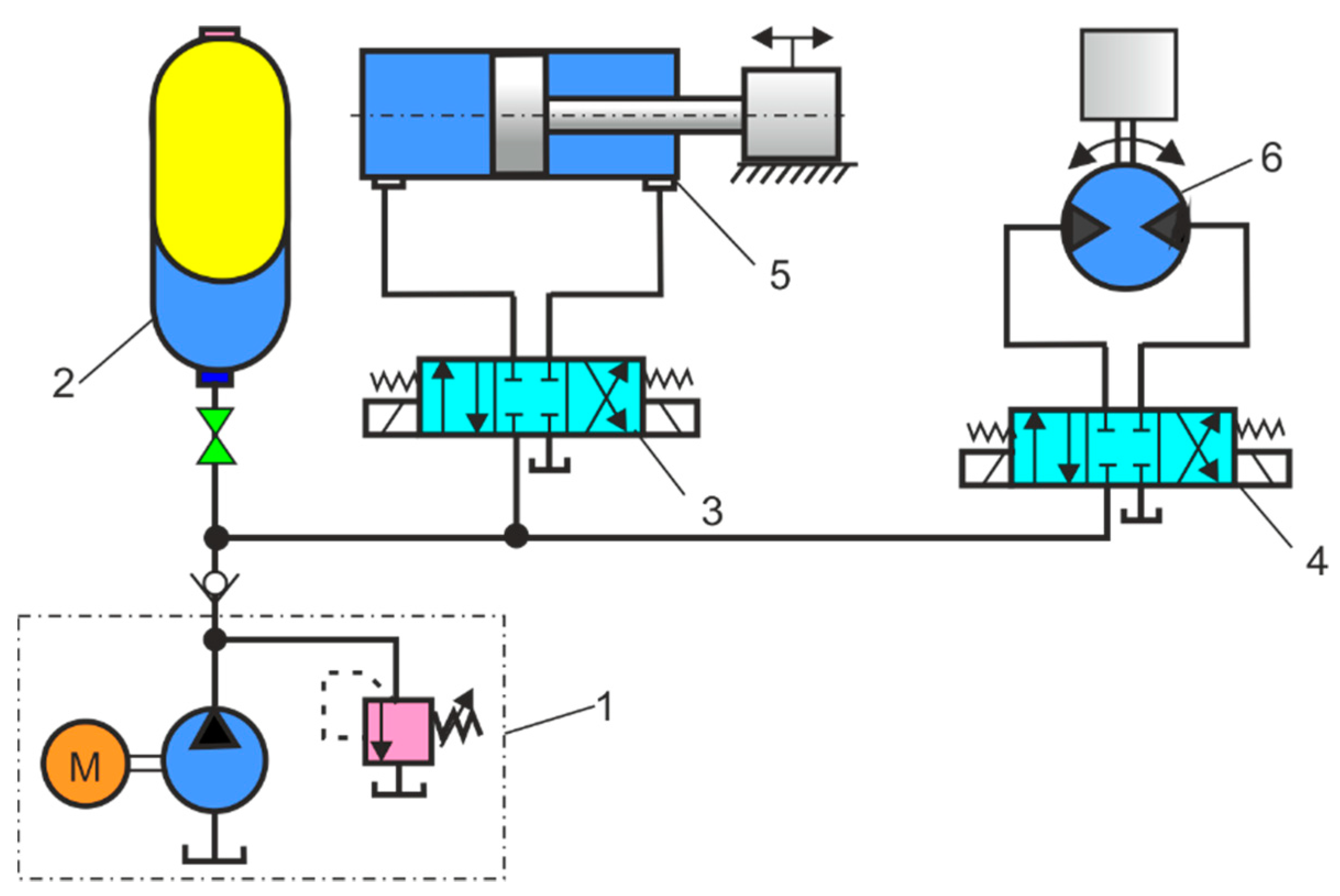
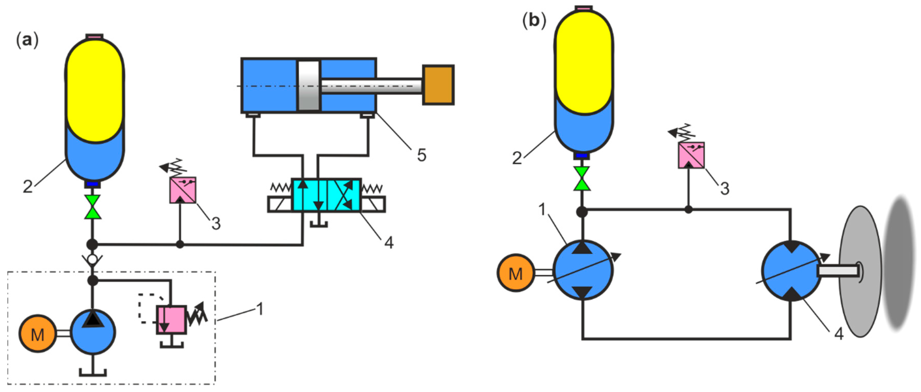
Figure 2 shows the hydraulic circuit for the different oil requirements of the cylinder and motor. The HPA, as well as a hydraulic fluid (oil) reservoir, provides an increase in the fluid requirement for one hydraulic actuator, a cylinder, or a motor. During breaks in the work of the hydraulic cylinder and hydraulic motor, the HPA is recharged. Due to the use of HPA, it is possible to install pumps with less power, which reduces hydraulic and heat losses, and then the cooler may be redundant.
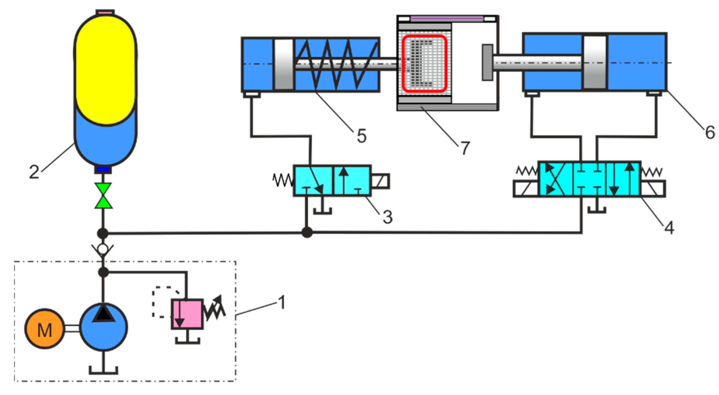
Figure 3 shows the hydraulic circuit for the short-time oil demand in the cylinder in an injection moulding. HPA as a hydraulic fluid store ensures that large fluid needs are in demand in a short time. In die-casting machines, injection-moulding machines, and plastic-blowing machines, large amounts of oil in the cylinders are required in a short time during the injection phase. In most cases, such shutdown systems require minimal oil during normal operation.
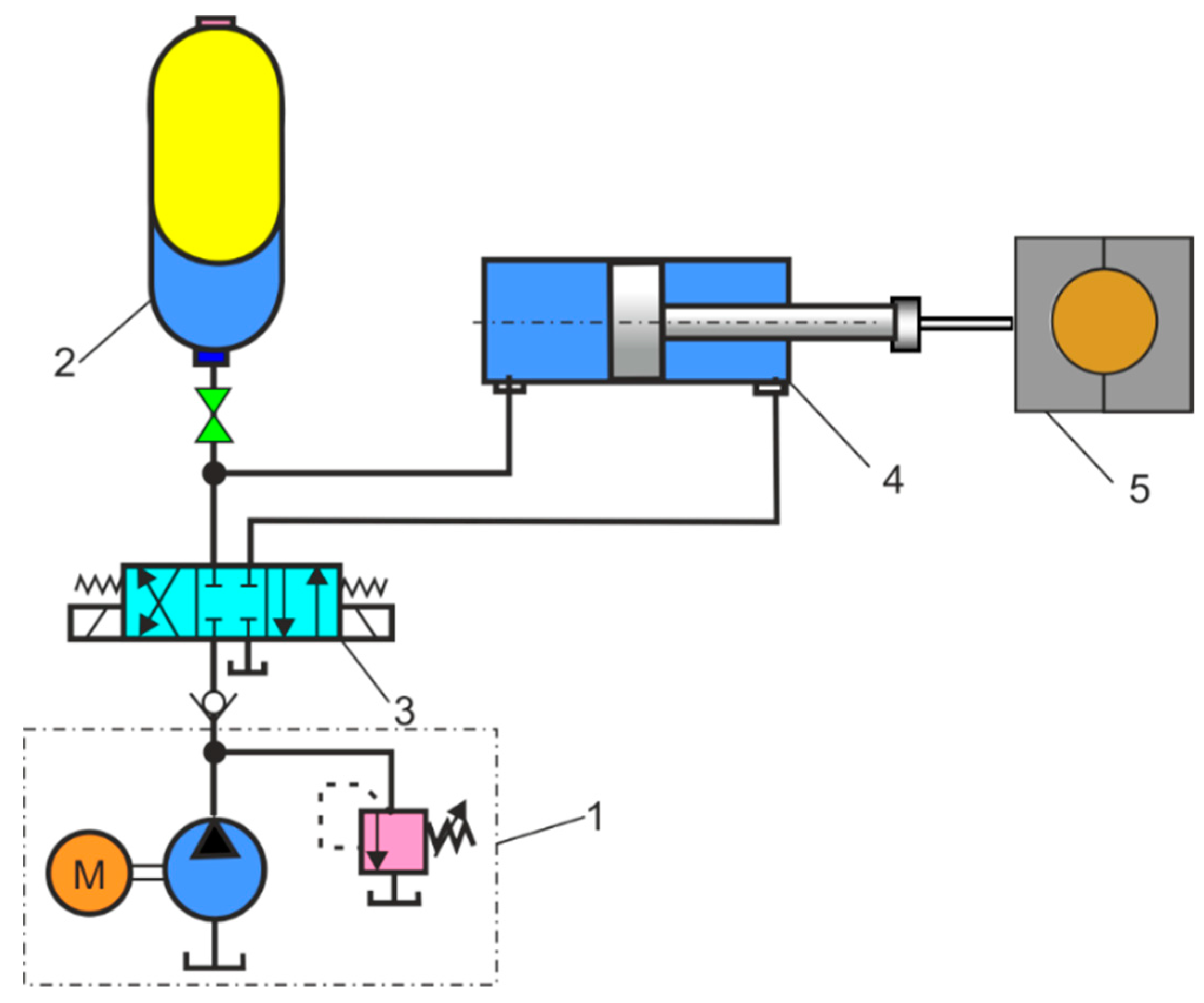
Figure 4 shows the hydraulic circuit for maintaining pressure in the cylinder to clamp the roller for a long time. Once the clamp pressure is reached, the hydraulic pump can be idled or used for other applications. The HPA maintains the required holding pressure throughout the process.
Figure 5 shows a hydraulic circuit where an HPA is used as a safety device in the event of a hydraulic pump or directional control valve failure. In this system, the on/off safety valve is connected to the bypass of the directional control valve, and the HPA in these applications is normally inactive.
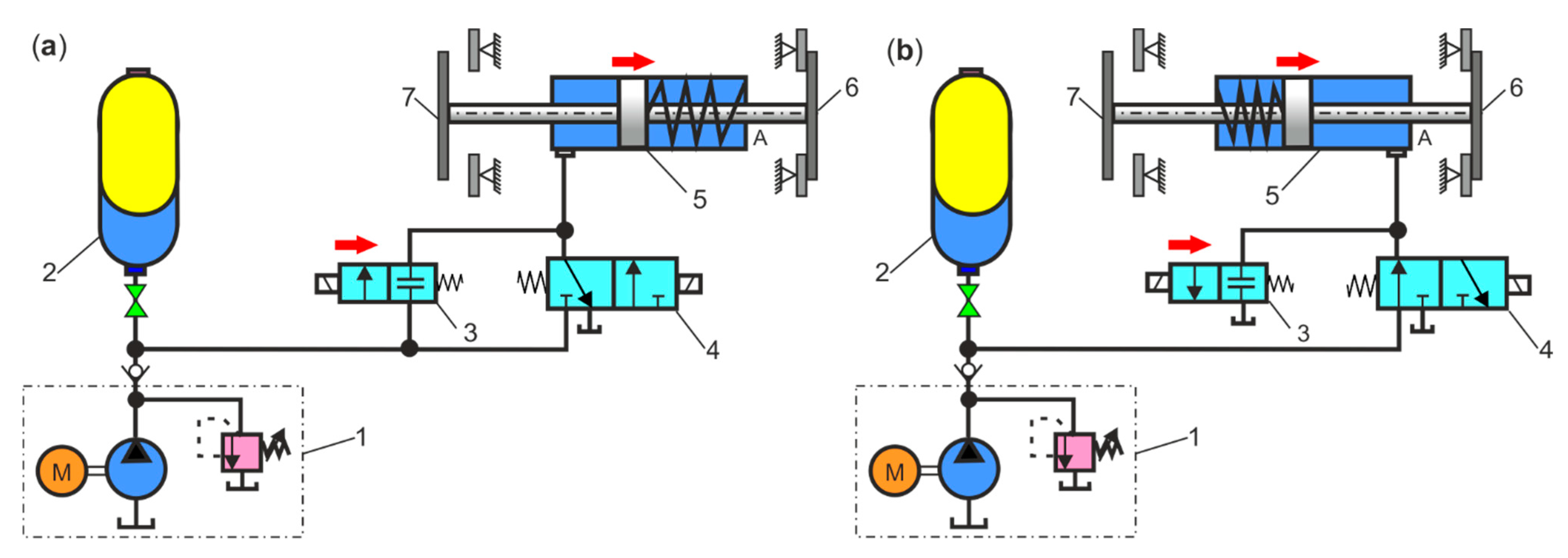
Figure 6a shows a hydraulic circuit where the HPA is used as an emergency stop device in the clutch and hydraulic brake unit. Therefore, the hydraulic energy needed is constantly available in the HPA to perform an emergency stop. HPA can be used, for example, to control the emergency brakes, funicular rail, or gondola doors. Figure 6b shows a hydraulic circuit where the HPA is used as an emergency stop device in the inverted clutch and the mechanical brake unit. This type of system is often recommended when braking is performed with a spring mechanical brake and the HPA and cylinder operate the clutch clamp. In the event of a directional control valve failure, the emergency on/off valve will work.
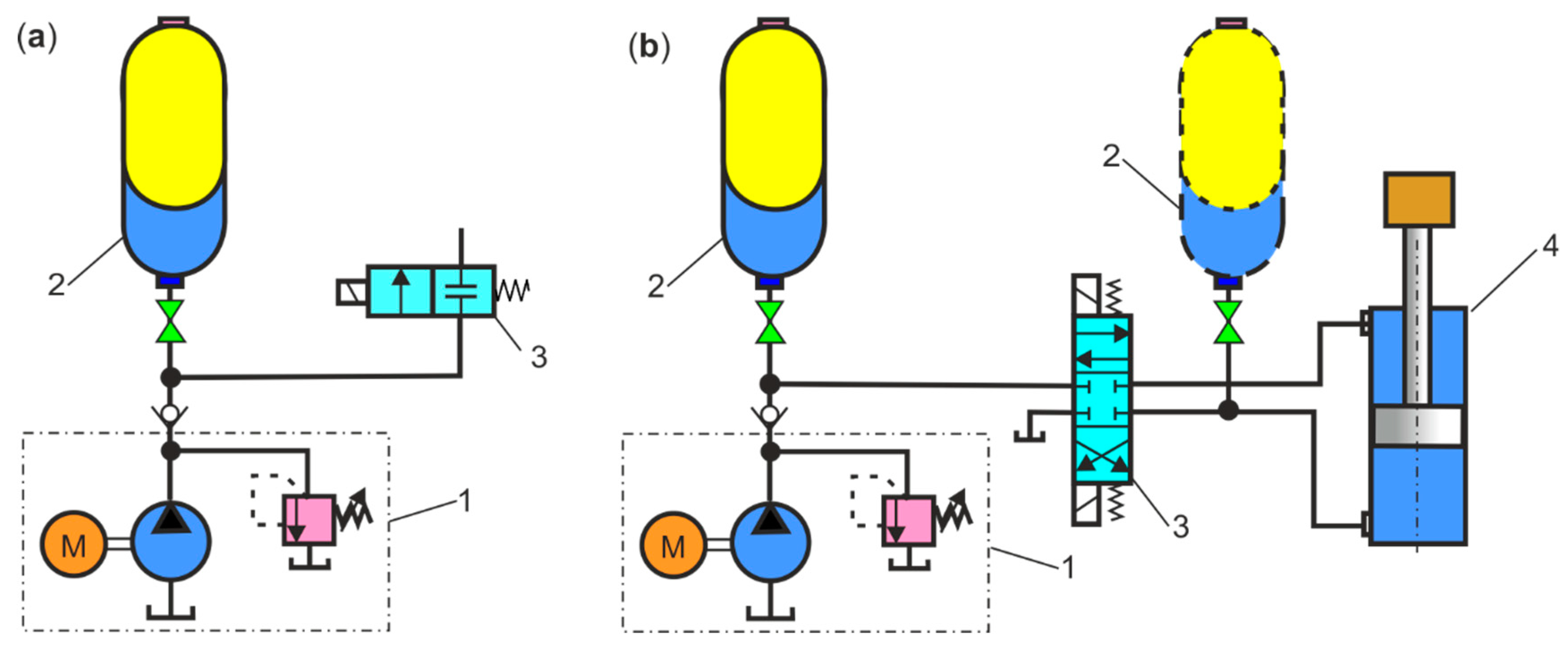
Figure 7a shows a hydraulic circuit with HPA as a leak compensator that compensates for oil loss due to internal or external leaks over an extended period of time when the cylinder is pressurised but not operating. An oil leak causes a pressure drop in the hydraulic circuit, which is limited by the pressure switch. Figure 7b shows a hydraulic circuit with HPA as a thermal expansion compensator, which is especially effective when heat causes the volume of fluid in the system to expand. Changes in the volume of a liquid resulting from changes in temperature within a closed circuit cause an increase in pressure. HPA can be used to relieve such pressure fluctuations. The increase in pressure in the hydraulic circuit is limited by the pressure switch.
Figure 8a shows a hydraulic circuit with an HPA as a hydraulic shock absorber (water hammer absorber), which is installed near the rapidly closed shut-off valve. When rapidly closing, a valve creates a compression wave. This compression wave travels at the speed of sound to the end of the pipe and back again to the closed valve, causing an increase in pressure. The resulting rapid pressure pulsations or high-pressure surges may cause damage to the components of the hydraulic system. One of the important applications of HPAs is the elimination of hydraulic shocks. Figure 8b shows a hydraulic circuit with an HPA as a pressure pulsation damper, which is installed near the pump or actuators (cylinders, motors) as a pulsation generator. In many hydraulic systems, pressure pulsations and fluctuations can cause damage, decrease efficiency, and even cause safety risks. HPAs can effectively damp the pressure pulsation and ensure the smooth and safe operation of the hydraulic system. The bladder-type HPA is adapted to absorb shock pressure and eliminate pressure pulsations.
  • Notes on future and frontier research methods
As can be seen from the presented diagrams, HPAs can be used in various applications in the industry. Researchers should design novel types of HPAs with an improved performance in specific application areas. Significant pressure drops occur during HPA charging and discharging, especially in small, variable-frequency hydraulic systems. For this reason, a new type of HPA should be designed with a mechanism to compensate for the nonlinear relationship between gas pressure and volume.

2.3. Hydraulic System with Energy Regeneration

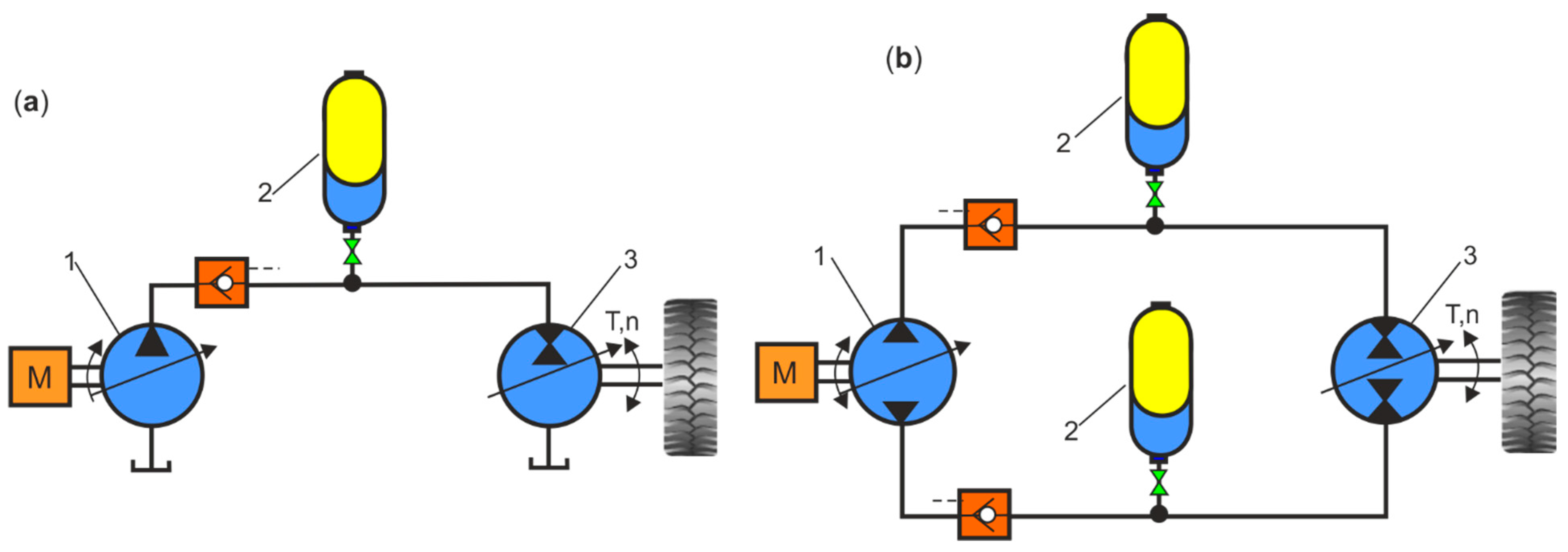
Hydraulic transmission systems with HPAs are widely used in various industries, construction machinery, hydraulic vehicles, regenerative suspensions, and wave energy converters [43]. The recovering and regeneration (recuperation) of energy, called regenerative braking, is the most important feature of hydrostatic propulsion systems. Energy regeneration is required in modern energy-saving hydraulic machines. In hydraulic systems, the regenerative energy is the static energy that returns to the HPA when the hydraulic motor is slowed or its load drops. Energy storage in HPAs is only viable when the propulsion system is cyclically operated at high efficiency. The efficiency of energy recovery, according to the efficiency values given for the hydraulic system, is 69% [44]. The energy stored in the HPA is used to accelerate the propulsion system. Examples of general hydraulic propulsion with regenerative braking and energy storage in open-loop and closed-loop systems with HPA are shown in Figure 9. In regenerative hydraulic propulsion systems, a pump is used as the primary energy source, an accumulator as the secondary energy source, and a reversible drive unit with secondary control, which, depending on the direction of energy transmission, works as a motor or pump. In such systems, a two-way flow of energy is possible. In one direction, energy is transferred from the pump and accumulator to the motor/pump. Conversely, the energy recovered from braking (regenerative braking) is transferred from the motor/pump to the hydraulic accumulator, where the potential energy can be stored.
Energy-regeneration systems are a key factor in improving energy efficiency in hydraulic machinery. In [45], an energy regenerative system was proposed for an accumulator-powered hydraulic impulse test device. Mathematical analysis and simulations show that a hydraulic system in the impulse testing system with an accumulator can reduce the energy consumption by 15% over the system without an accumulator in the cycle, while the energy efficiency of the hydraulic impulse testing system increases from 62.82 to 75.71% due to the use of accumulator. In [46], the purpose of the research was to increase the efficiency of the hydraulic system by introducing the concept of a regenerative system. The regenerative circuit is used to accelerate the extension stroke of a single rod, double-acting, hydraulic cylinder. In [47], to reduce energy losses in the relief valve, a hydraulic energy regeneration unit (HERU) was connected to the outlet of this valve, which reduces the pressure drop between the inlet and the outlet of the relief valve. Experimental results show that a relief valve with HERU connected to its outlet can achieve better pressure regulation properties. The energy recovery efficiency saved by HPAs is up to 83.6%, with a higher HPA pre-charge. The design of the HERU bleed valve has been proposed to allow a better performance and higher efficiency in the hydraulic system. The article [48] deals with the design of an experimental rig with the hydromechanical system and energy regeneration. The proposed experimental rig is a scaled simulator of a heavy-vehicle hydrostatic driveline. In [49], a novel energy-saving hydraulic system based on a hydrostatic system and an HPA was proposed. A hydraulic system efficiency model was developed and used to estimate the energy utilisation and recovery of the system under different conditions. A model validation indicated that the energy recovery potential of the system ranged from 32% to 66% depending on the pump/motor displacement. In this paper [50], electric and hydraulic regeneration methods are studied to recover potential energy from an electro-hydraulic forklift truck. In the hydraulic regeneration system, the hydraulically operated forklift is equipped with an energy recovery system consisting of pressure accumulators to store energy and a hydraulic digital valve package for precise leakage-free flow control.
In [51], various energy storages based on a Sun-Cycle LiFePO4 type battery, Maxwell Technologies BCAP0050 P270 S01 type ultracapacitors, and Parker Hannifin A2N0058D1K type HPA were compared. Both the ultracapacitor and HPA are designed to have the same energy storage capacity. Charge and discharge tests of energy storages were carried out to compare their power density, energy density, cost, and efficiency. The tests showed that the power density in the HPA was 21.7% higher compared to the ultracapacitors. Moreover, the cost/power ratio in the hydraulic accumulator was 2.9 times smaller than the ultracapacitors. Under the conditions tested, the overall energy efficiency of the HPA was 87.7%, and the overall energy efficiency of the ultracapacitor was 78.7%. The parameters of the three energy storages tested are compared and summarised in Table 1. Table 2 compares the energy densities, and Table 3 compares the power densities of the three energy storages tested: battery, ultracapacitor, and HPA.
The higher energy efficiency in HPAs and the better power density compared with ultracapacitors could be determining factors in choosing a hydraulic system over an electric system for a specific application, where there is a need to rapidly charge or discharge energy storage devices, such as in the case of regenerative breaking.
  • Notes on future and frontier research methods
With the development of renewable energy research and energy-saving technologies, energy regeneration and conversion (ERC), energy storage technology (EST), and hydraulic transmission systems (HTS) should also be developed.

2.4. Hydraulic Hybrid System

Hybrid systems are generally classified on the basis of the configuration of the drivetrain and how they store energy. Originally, hydraulic hybrid technology was designed for military vehicles, trucks, vans, and buses. The concept of the Hydro-Bus was developed in Hanover in the early 1980s. For heavy municipal vehicles (garbage trucks), loading equipment and construction machines operating in short working cycles (with frequent stops), Bosch Rexroth has developed a parallel hybrid drive with hydrostatic regenerative braking (HRB—Hydrostatic Regenerative Braking System) [52]. The research also concerned hydraulic hybrid drives in such vehicles as SUVs: Hummer H3, Nissan Titan, Pathfinder, Dodge Durango. Ford Explorer, and GMC Yukon [53]. One of the first hydraulic parallel hybrid drives introduced to urban vehicles was the Parker Hannifin CBED (Cumulo Brake Energy Drive) system [54]. The latest solution to hybrid hydraulic drives was developed in cooperation between Bosch and Peugeot Citroën PSA [55]. In [56], the latest technological advances and breakthroughs in mechanical–electric–hydraulic hybrid energy storage systems in vehicles are analysed and discussed in detail, which are divided into four categories: passenger cars, minibuses and buses, commercial vehicles, and special vehicles.
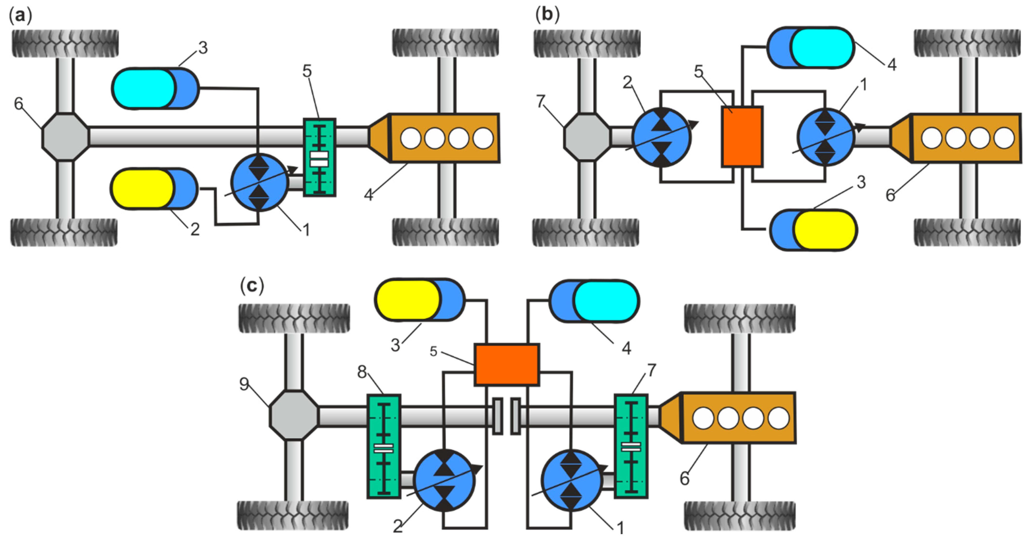
Figure 10 shows the basic structures of hydraulic hybrid drives (HHD), such as parallel hydraulic hybrid (PHH), series hydraulic hybrid (SHH), and series parallel hydraulic hybrid (SPHH) [57]. In the PHH, the internal combustion engine (ICE) is mechanically connected to the wheels of the vehicle. When high power is required, the internal combustion engine and the hydraulic motor can operate in parallel. During braking, the hydraulic motor operates like a hydraulic pump and transmits the recovered braking energy to the high pressure HPA. In the SHH, the ICE drives the hydraulic pump at optimum speed, which transfers the hydraulic energy to a hydraulic motor connected to the vehicle’s wheel drive differential, and excess energy is stored in the HPA. During braking, the hydraulic motor operates as a hydraulic pump and transfers the recovered energy to the high-pressure HPA. An SPHH has the advantages of both SHH and PHH types. These two types of drive provide a high performance throughout the vehicle speed range in different driving situations. The SPHH control system should ensure smooth mode switching during drives. However, the structure of the SPHH is complex and requires reliable drive operation.
In [58], the focus was on thermodynamic effects and their influence on the energy savings potential of HHD by using endoreversible thermodynamics as an ideal modelling framework. In this case, the energy savings for accelerating the vehicle are expected to be around 10% and the reduction in the energy transferred to conventional disc brakes to be around 58%. In [59], factors that influence the speed of energy recovery in the braking system with energy recovery in a hybrid hydraulic vehicle (HHV) were studied. In [60], a novel energy recovery system was proposed for hybrid hydraulic excavators based on a digital pump with an energy recovery function. The simulation results showed that this hybrid system could decrease the system input energy by 78.1%.
In [61], different vehicle configurations were compared: a conventional internal combustion engine (ICE), series hybrid electric vehicle (SHEV), series hydraulic hybrid vehicle (SHHV), parallel hybrid electric vehicle (PHEV), parallel hydraulic hybrid vehicle (PHHV), electric vehicle (EV), and hydraulic-electric hybrid vehicle (HEHV). The results of the study show that the fuel consumption was 21.80% lower in the SHHV compared to the SHEV and the fuel consumption was 3.80% lower in the PHEV compared to the PHHV. Furthermore, the HEHV consumed 11.4% less electricity than the EV. Table 4 shows a comparison of the economic savings of various hybrid vehicle configurations in relation to the base ICE.
Currently, the most important limitations related to the use of vehicles with a hydraulic hybrid drive are the noise, large size, and complexity of the structure. The latest generations of hydraulic motors that produce a high torque and at the same time maintain the small size of the device allow the use of these solutions in such utility vehicles as garbage trucks or city buses.
  • Notes on future and frontier research methods
Research into hybrid hydraulic drives should aim for smaller, lighter, and more efficient HPAs that can be used in both small consumer vehicles and large, heavy-duty, and commercial vehicles. For example, for a hydraulic hybrid drive system, a new HPA piston should be designed, in which the shell is made of carbon-fibre-reinforced plastic and the piston of aluminium. At the same time, the thermodynamic behaviour of the liquid and gas, as well as their interaction with carbon fibre, must be determined in detail. The implementation of HPAs from carbon fibre limits their use in high-pressure systems. The cost of using carbon fibre is still high.

3. HPA Calculation Parameters and Computational Models

In the catalogues of HPA manufacturers, there are formulas useful for selecting the required parameters of HPA for various applications, most often the required nominal volume and pre-charge pressure are calculated. For HPA estimation calculations, accumulator calculators are available on the Internet. Application software Hydac ASPlight is also available to select HPAs based on their parameters. ASPlight online tools are used for optimal hydraulic accumulator calculations, such as volume, pressure ratio, and maximum and minimum operating pressures, taking into account the behaviour of the real gas [62].
Basic HPA calculation parameters and computational models of energy storage and thermodynamic cycle are presented.

3.1. HPA Calculation Parameters

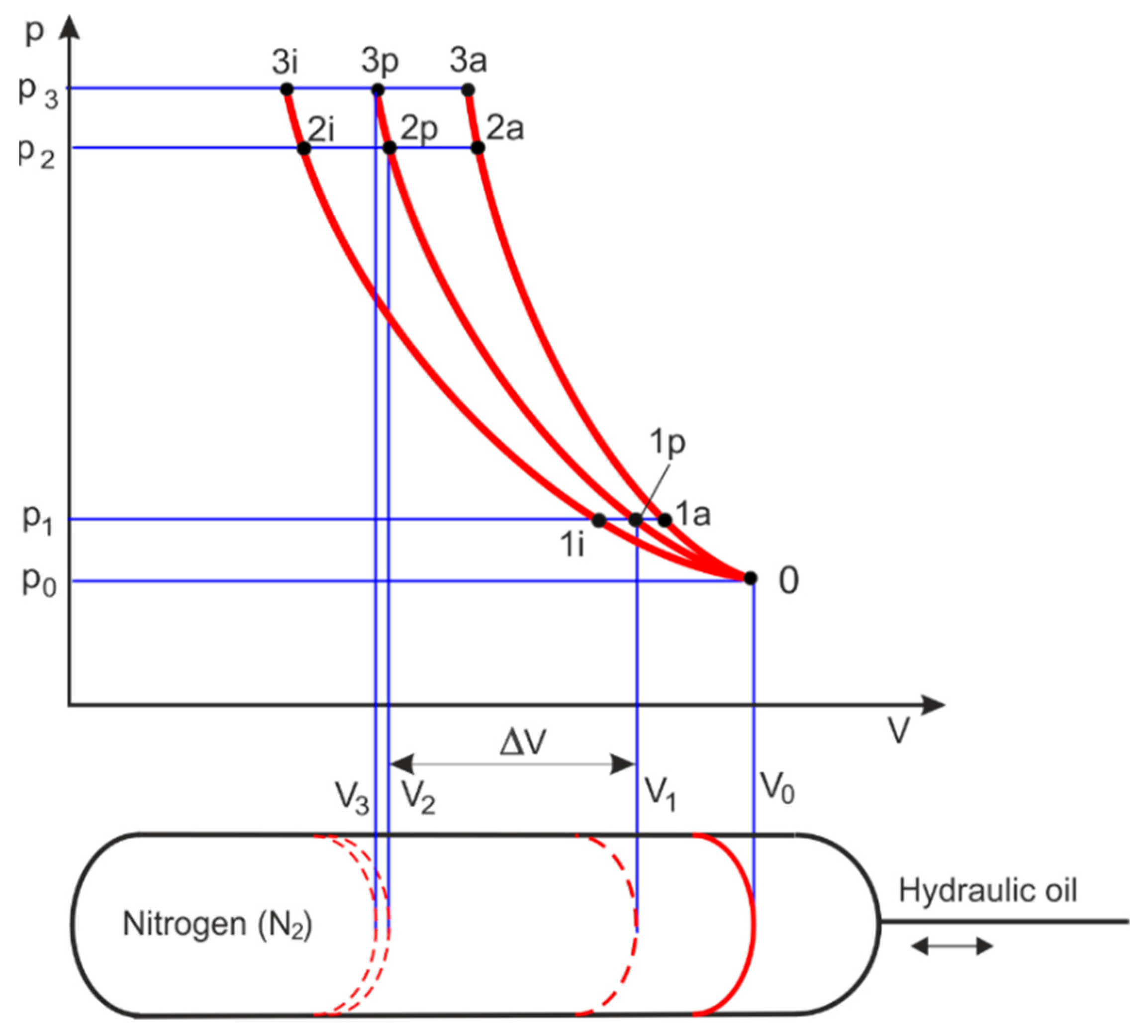
The size of the HPA depends on many different variables; thus, it is best to use methods to select them on the basis of thermodynamic principles. The method of selecting HPA is presented when only the initial parameters, such as the charging volume V0 at the pressure p0, are known. This method is used to determine the operating and energy parameters of HPA and then to select an HPA from the manufacturers’ catalogues. Figure 11 shows the pressure–volume diagrams of the gas compression and expansion of an ideal gas (N2 nitrogen) in an HPA according to adiabatic (a), isothermal (i), and polytropic (p) processes.
The following parameters are marked in Figure 11: p0 is the relative pre-charge pressure, p1 is the minimum working relative pressure of the hydraulic circuit, p2 is the maximum relative working pressure of the hydraulic circuit, p3 is the calibration relative pressure of the safety valve, V0 is the volume of gas under the pressure p0, V1 is the volume of gas under the pressure p1, V2 is the volume of gas under the pressure p2, V3 is the volume of gas under p3 pressure, and ΔV is the useful (effective) volume. The actual conditions for the gas expansion and expansion processes in the HPA follow the general polytropic process with exponent n, but under state conditions it is assumed that n = κ = 1.4 for the adiabatic process and n = 1 for the isothermal process. In ideal slow-changing gas compression and expansion, isothermal processes are assumed, and in ideal fast-changing gas compression and expansion, adiabatic processes are assumed. For pressures above 20 MPa, the real gas behaviour deviates considerably from the ideal, which reduces the effective fluid volume.
To calculate and select the HPA, the pressure ratios are determined: pre-charge pressure ratio p1/p0, working pressure ratio p2/p1, maximum working pressure ratio p2/p0, and maximum compression pressure ratio p3/p0. The pre-load pressure p0 for HPA is generally computed using the following formula. p0 ≤ 0.9 p1. In general, it is necessary to check that the pre-charge pressure p0 is within the following limits 0.25 p2p0 ≤ 0.9 p1 [63]. The pressure p3 is equal to the maximum allowable pressure PS.
When selecting HPA, the operating parameters of the hydrostatic system are taken into account, such as the usable volume ΔV, nominal volume V0 and compression work W12 or expansion work W21 for specific pressure ratios.
The HPA calculation parameters are the result of the polytropic process:
p 0   V 0 n = p 1   V 1 n V 1 = V 0   ( p 0 p 1 ) 1 / n
p 1   V 1 n = p 2   V 2 n V 2 = V 1   ( p 1 p 2 ) 1 / n   V 2 = V 0   ( p 0 p 2 ) 1 / n
useful (effective) volume of HPA
Δ V = V 1 V 2 = V 0   [ ( p 0 p 1 ) 1 / n ( p 0 p 2 ) 1 / n ]
the volume required for the polytropic process
V 0 = Δ V ( p 0 p 1 ) 1 / n ( p 0 p 2 ) 1 / n
When an HPA is used in the processes of rapid gas expansion and compression under ideal conditions, the adiabatic process (n = κ = 1.4) is considered. Then, the required volume is
V 0 a = Δ V ( p 0 p 1 ) 1 / κ ( p 0 p 2 ) 1 / κ
When an HPA is used for slow gas expansion and compression processes to compensate for volume (leakage), the isotherm process (n = 1) is considered. Then, the required volume is determined by
V 0 i = Δ V ( p 0 p 1 ) ( p 0 p 2 )
Under actual conditions, the initial compression of the gas in the HPA from State 0 to State 1 occurs according to the isothermal process, and the gas compression from State 1 to State 2 occurs according to the polytropic process. Then, the usable volume of the accumulator is calculated according to the formula
Δ V = V 1 i V 2 p = V 1 i V 1 p   ( p 1 p 2 ) 1 / n
The volume difference in initial State 1 during polytropic and isothermal compression results in a relative error, which is defined as follows
ε = V 1 p V 1 i V 1 p + V 1 i 2 = 2   ( p 0 p 1 ) 1 / n p 0 p 1 ( p 0 p 1 ) 1 / n + p 0 p 1
The gas pre-charge pressure p0 must be as close as possible to the minimum working pressure p1 to obtain the maximum storage energy. The maximum gas pre-charge pressure is found from the relationship p0/p1 ≤ 0.9. Formula (8) shows that for pre-charge adiabatic compression with a pressure ratio p0/p1 = 0.9, the maximum volume error is ε = 3%. If the differences in volumes V1p and V1i are small, it is reasonable to assume that
V 1 p V 1 i = V 0   p 0 p 1
  • Notes on future and frontier research methods
The polytropic process of compression and expansion of real gas in an HPA must be considered. The instantaneous polytropic index n is an indicator of the effect of heat transfer during an HPA charging or discharging process. However, theoretical predictions for the polytropic index n should be tested experimentally.

3.2. Energy Stored in the HPA

When the gas is compressed, the change in volume is negative, and when the gas is expanded, the change in volume is positive.
The usable volume after compressing a gas at the change of State 1 → 2:
Δ V 12 = V 2 V 1 = V 1   ( p 1 p 2 ) 1 / n V 1   = V 1 [   ( p 1 p 2 ) 1 / n 1 ]
Taking into account the isothermal pre-charge of the HPA (10) will take the form
Δ V 12 = V 0   p 0 p 1 [   ( p 1 p 2 ) 1 / n 1 ]  
The usable volume after the expansion of a gas at the change of State 2 → 1:
Δ V 21 = V 1 V 2 = V 2   ( p 2 p 1 ) 1 / n V 2   = V 2 [   ( p 2 p 1 ) 1 / n 1 ]
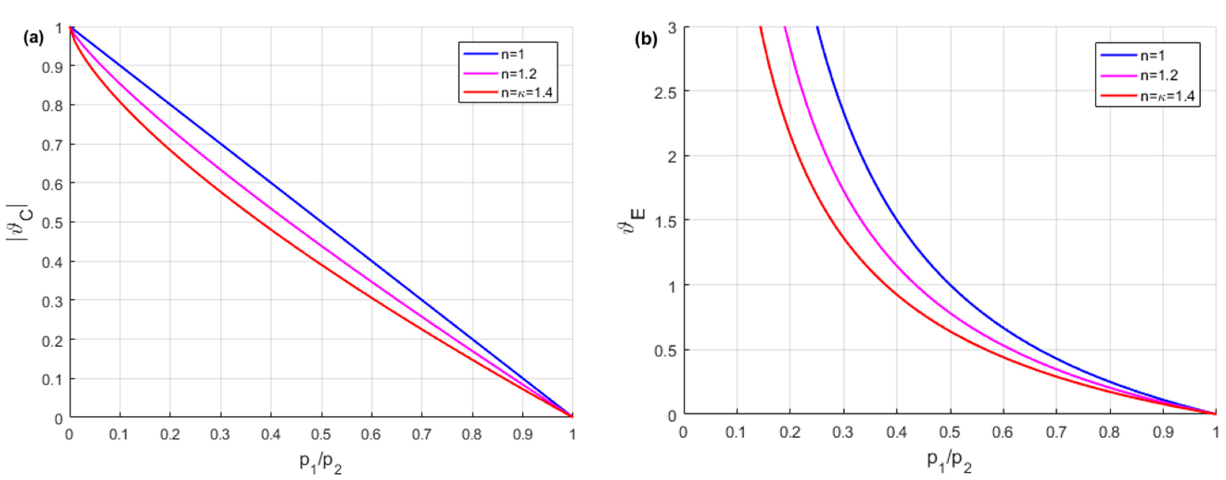
The gas compression volume factor is determined from (12):
ϑ C = Δ V 12 V 1 = ( p 1 p 2 ) 1 / n 1
The gas expansion volume factor is determined from (13):
ϑ E = Δ V 21 V 2 = ( p 2 p 1 ) 1 / n 1
Figure 12 shows the volume factors versus pressure ratio curves for HPA gas compression and expansion.
The pressure–volume works W21p, W21a, and W21i for the HPA gas compression process at the change of State 1 → 2 for polytropic, adiabatic, and isothermal processes, respectively, are given by
W 12 p = p 1   V 1 n 1 [ 1 ( p 1 p 2 ) 1 n n ]
W 12 a = p 1   V 1 κ 1 [ 1 ( p 1 p 2 ) 1 κ κ ]
W 12 i = p 1   V 1   ln ( p 1 p 2 )
The pressure–volume works W21p, W21a, W21i for the HPA gas expansion process at the change of State 2 → 1 for polytropic, adiabatic and isotherm processes, respectively, are given by
W 21 p = p 2   V 2 n 1 [ 1 ( p 2 p 1 ) 1 n n ]
W 21 a = p 2   V 2 κ 1 [ 1 ( p 2 p 1 ) 1 κ κ ]
W 21 i = p 2   V 2   ln ( p 2 p 1 )
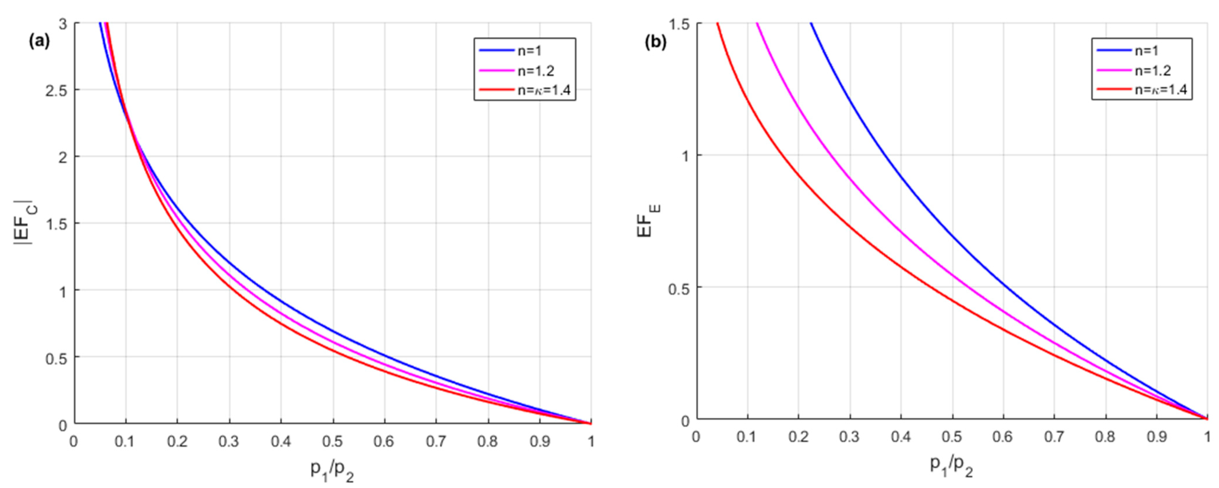
HPA energy is the energy supplied to the gas during pressure–volume work. The HPA energy factor (EF) was introduced as the ratio of gas compression or expansion work to the pV-product of energy capacity at the initial state of the process.
HPA energy factor for gas compression:
E F C = W 12 V 1   p 1 ,
HPA energy factor for gas expansion:
E F E = W 21 V 2   p 2 .
Figure 13 shows the curves of the energy factors versus the pressure ratio for the compression and expansion of the gas.
The energy quotient (EQ) was introduced as the ratio between usable energy and a pV-product that represents the given energy capacity of the HPA. The pressure–volume work W12p, W12a, W12i in compression processes were related to the maximum operating pressure p2 and the volume V1, which corresponds to the energy quotients EQp, EQa, and EQi of the HPA, for polytropic, adiabatic and isothermal compression, respectively.
E Q p = W 12 p V 1   p 2 = 1 n 1 p 1 p 2 [ 1 ( p 1 p 2 ) 1 n n ]
E Q a = W 12 a V 1   p 2 = 1 κ 1 p 1 p 2 [ 1 ( p 1 p 2 ) 1 κ κ ]
E Q i = W 12 i V 1   p 2 = p 1 p 2   ln ( p 1 p 2 )
Figure 14 shows the curves of the HPA energy quotient versus the operating pressure ratio. The selection of an energy-saving HPA results from the maximum energy quotient EQ as a function of the operating pressure ratio p1/p2, E Q m a x = E Q / ( p 1 / p 2 ) = 0 .
The values of the maximum energy quotient EQmax for various compression processes shown in Figure 14 were generated during numerical calculations. From these data, useful formulas for calculating the energy storage ESp, ESa, and ESi of the HPA for polytropic, adiabatic, and isothermal compression were determined, respectively:
E S p = 0.3349   V 1   p 2   = 0.3349   V 0   p 0   p 2 p 1  
E S a = 0.3080   V 1   p 2   = 0.3349   V 0   p 0   p 2 p 1  
E S i = 0.3679   V 1   p 2   = 0.3349   V 0   p 0   p 2 p 1  
Optimal selection of HPA parameters takes into account the limitations that result from the hydraulic system.
First limitation. The usable volume ΔV of the HPA must be greater than or at least equal to the required volume change ΔVh in the hydraulic system, ΔV ≥ ΔVh:
Second limitation. The expansion work W21 of the gas in the HPA must be greater than or at least equal to the work performed Wh in the hydraulic system, W21Wh.
Third limitation. The pressure drops Δp in the HPA must be less than or at least equal to the allowable operating pressure difference Δph in the hydraulic system, Δp ≤ Δph.
  • Notes on future and frontier research methods
When HPA is used as an energy storage, the most critical issue is its size and product of volume and pressure. HPA parameters must be optimised so that they are consistent with the real cycle of the propulsion system. The HPA energy storage capacity offers huge benefits in terms of reduced energy consumption in the hydraulic powertrain. The subject of future research should be the use of the finite element method (FEM) as a tool to support the HPA research and design process. In the process of developing HPA models using FEM, model discretisation, defining initial conditions, formulating boundary conditions, and defining external loads are taken into account.

3.3. Thermodynamic Cycle of HPA

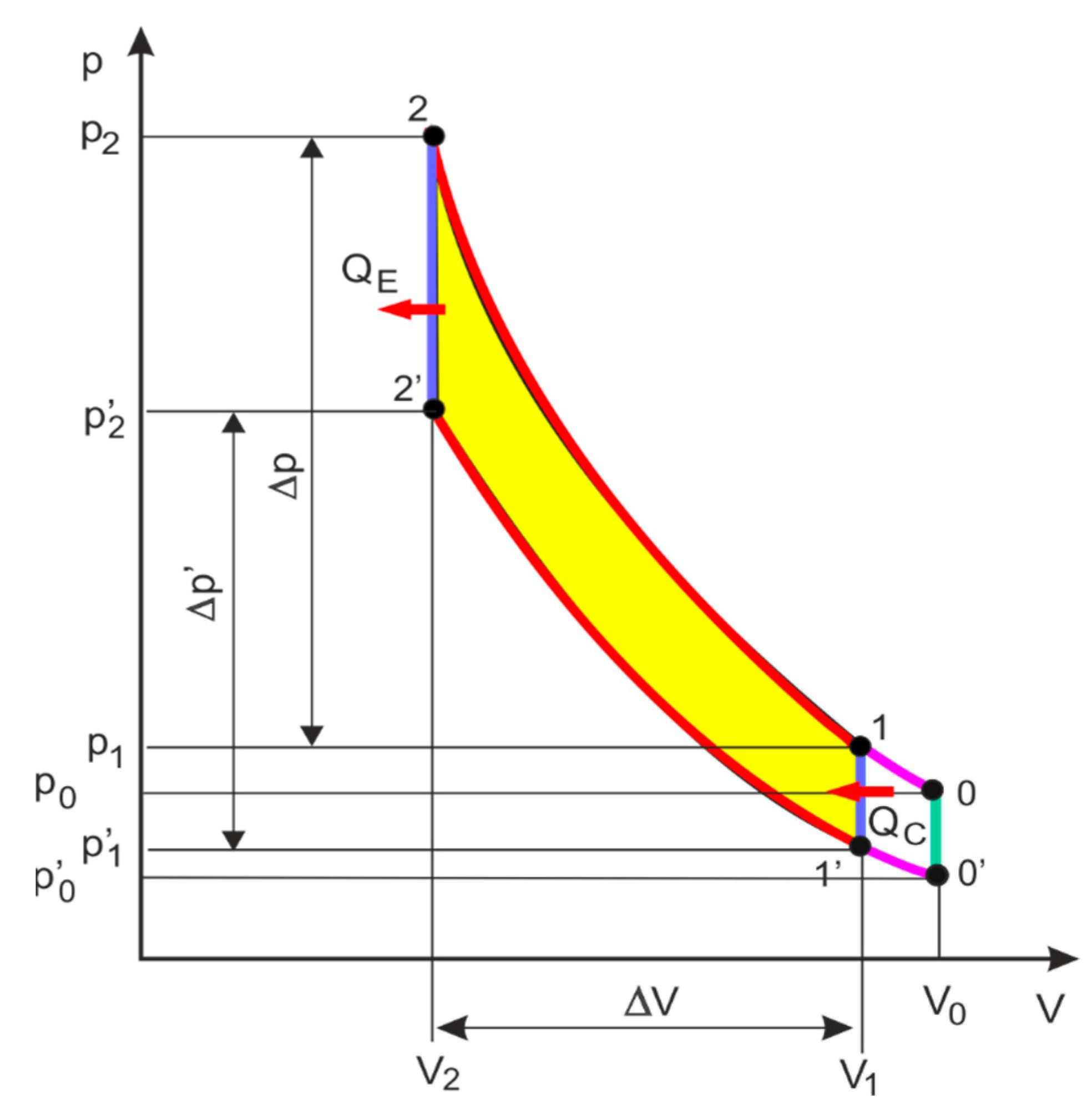
When HPA is selected, its thermodynamic cycles, which take into account the heat exchange of the gas with the ambient environment, should be taken into account. If the ambient temperature changes, then the temperature of the gas in the HPA also changes, which affects the pressure in the accumulator. The actual thermodynamic cycles are determined on the test stand for measurement of the indicated parameters. When selecting and calculating the HPA, various thermodynamic cycles of PV (pressure–volume) are considered. Thermodynamic cycles determined from ideal gas processes, such as adiabatic, isothermal, isochoric, and isobaric, are most often considered. In HPA modelling, the PV thermodynamic cycle was taken into account, in which the isochoric and polytropic processes of an ideal gas are represented. Figure 15 shows the PV diagram of the thermodynamic cycle for ideal gas processes in an HPA.
PV diagram of the thermodynamic cycle for ideal gas processes in an HPA which consists of isothermal pre-charge 0 → 1, polytropic compression 1 → 2, isochoric cooling 2 → 2′, polytropic expansion and 2′ → 1′, isochoric heating 1′ → 1, isothermal expansion 1′ → 0′, and isochoric heating 0′ → 0. The HPA operating cycle highlighted in the PV diagram includes polytropic compression 1 → 2, isochoric cooling 2 → 2′, polytropic expansion 2′ → 1′, and isochoric heating 1′ → 1.
Heat in isochoric heating at the change of State 1′ → 1:
Q H = m   c v   ( T 1 T 1 ) = V 1 κ 1   ( p 1 p 1 )
Heat in isochoric cooling at the change of State 2 → 2′:
Q C = m   c v   ( T 2 T 2 ) = V 2 κ 1   ( p 2 p 2 )
where m is the mass of gas and cv is the specific heat at constant volume.
Heat transfer in isothermal compression at the change of State 1 → 2:
Q 12 i =   W 12 i = p 1   V 1   ln ( p 1 p 2 )
Heat transfer in isothermal expansion at the change of State 2′ → 1′:
Q 21 i = W 21 i = p 2   V 2   ln ( p 2 p 1 )
Heat transfer in a polytropic compression at the change of State 1 → 2:
Q 12 p = κ n κ 1   W 12 p = κ n κ 1 p 1   V 1 n 1 [ 1 ( p 1 p 2 ) 1 n n ]
Heat transfer in a polytropic expansion at the change of State 2′ → 1′:
Q 21 p = κ n κ 1   W 21 p = κ n κ 1 p 2   V 2 n 1 [ 1 ( p 2 p 1 ) 1 n n ]
The efficiency of HPA is, therefore,
for isothermal processes
η H P A = Q 21 p Q 12 p = p 2   V 2   ln ( p 2 p 1 ) p 1   V 1   ln ( p 1 p 2 )
for polytropic processes
η H P A = Q 21 p Q 12 p = p 2   V 2   [ 1 ( p 2 p 1 ) 1 n n ] p 1   V 1 [ 1 ( p 1 p 2 ) 1 n n ]
The efficiency of HPA depends on thermodynamic processes and heat losses.
  • Notes on future and frontier research methods
In HPA calculations, real thermodynamic cycles should be assumed, which take into account changes in gas volume and pressure and heat transfer in various battery designs. Thermodynamic cycles adapted to heat transfer can be assumed, such as isothermal compression–polytropic expansion–isochoric heating, or polytropic compression–isochoric cooling–isothermal expansion. In calculating and testing HPA, not only should heat-exchange cycles be taken into account, but also heat transfer analysis with its surroundings should be performed. Both convective and conductive heat transfer occurs from the gas to the accumulator shell. This is also the case for the hydraulic fluid that is in direct contact with the accumulator shell. The accumulator shell will also experience conduction and will ultimately radiate and convect heat to its environment.

4. Dynamic Models of HPA

In [64], the main objective was to use theoretical analysis, computer simulation, and experimental research to study the impact of HPA parameters on the hydraulic parameters system. In [65], a mathematical model of HPA for passenger cars is presented, which consists of a body made of carbon-fibre-reinforced plastic (CFRP) and an aluminium piston. In [66], the authors focused on pressure pulsations in hydraulic systems, taking into account the characteristics and parameters of HPA. In [67], pressure surges in the hydraulic system and energy savings in HPA were simulated in the Matlab/Simulink environment. In [68], the mathematical modelling, design, and simulation of HPA were presented using a bond graph, which took into account the thermal effects of the system. In [69], multi-domain HPA modelling and simulation were considered, followed by a dynamic HHV study.
HPA dynamic models have been defined, such as: a thermodynamic model, a simulation model in Simscape Toolbox (Matlab/Simulink), a dynamic model in the time domain, and dynamic models of HPA as a pulsation damper and as a shock pulse damper in the frequency domain.

4.1. Thermodynamic Model of HPA

The ideal gas law states that for a given change in temperature, there will be a corresponding change in pressure in the accumulator. This makes temperature an important factor when sizing the HPA. Thermal ambient conditions must be taken into account when designing an HPA. To account for changes in pressure, temperature, and volume, the general law of the state of an ideal gas was applied:
p   ϑ =   R   T
where p is the absolute pressure, ϑ is the specific volume, T is the absolute temperature, and R is the ideal gas constant.
Generally, when HPA is chosen on the basis of catalogues, engineering calculations, and computer simulations, isothermal and adiabatic processes are assumed for an ideal gas. For real gases, the relations between the state parameters (p, V, T) are presented only by means of approximate equations from isothermal and adiabatic processes, which are not precise enough but facilitate the calculation of HPA parameters. Therefore, it is preferable to take into account real gases by introducing appropriate correction factors. The real volume for an isothermal change of state is given by V0 = Ci·V0i, and the real volume for an adiabatic change of state is given by V0 = Ca·V0a. The values of the Ci and Ca correction factors can be obtained from the diagrams provided in the HPA catalogues by the manufacturers [34].
In HPA calculations, the real gas equation of state is used in the form
p   ϑ = Z   R   T .
where Z is the gas compressibility factor; that is, the ratio of the specific volume ϑ of a real gas to the specific volume ϑ 0 of an ideal gas at the same temperature and pressure, Z = ϑ / ϑ 0 .
This is the case for a nitrogen factor of Z = 1 at the pressure p = 0–60 MPa and temperature T = 200–600 K [70]. If HPAs operate at higher pressures, then the real gas equations of state should be used. In [71], the limitations and precision of the application of various real gas equations were analysed, taking into account such equations as van der Waals, Beat–Tie–Bridgeman equations, Benedict–Webb–Rubin (BWR) equations, and Soave–Redlich–Kwong equations. In the work [72], the real state equation was determined using the BWR state equation, taking into account the thermal model of the HPA time constant. In [73], the thermodynamic characteristics of energy storage and release have been elucidated by simulation under real test conditions. The HPA thermodynamic model takes into account heat transfer and the gas model [74]. In [75], thermal time constants based on HPA experimental data are presented.
The HPA models take into account the polytropic processes of compression and expansion of an ideal gas. The Poisson relation between pressure and temperature for a polytropic process is given as follows:
p   V n = c o n s t
In polytropic processes of real gas compression and expansion, it is difficult to measure the actual value of the polytopic exponent n. Therefore, a method for calculating the approximate exponent na of the real gas has been proposed.
p   V n a = c o n s t p 1   V 1 n a = p 2   V 2 n a p 2 p 1 =   ( V 1 V 2 ) n a
To determine the approximate exponent na, the equation of state (40) was logarithmized on both sides,
ln ( p 2 p 1 ) = n a ln ( V 1 V 2 )
The approximate exponent na is the angle of inclination of the secant line connecting States 1 → 2 of the real polytropic processes:
n a = ln ( p 2 p 1 ) ln ( V 1 V 2 ) = ln p 2 ln p 1 ln V 1 V 2
The presented method for determining the approximate polytropic exponent na has practical applications, because the equations of ideal gas processes can be used when selecting the HPA.
The gas absorbs the thermal energy of the WC from the surroundings and gives the WC work to the surroundings. The HPA thermodynamic model takes into account the principle of energy conservation:
m g   d u d t = d Q C d t d W C d t
where mg is the mass of the gas and u is the internal energy of the gas.
The heat exchange between the gas and the surroundings is
d Q C d t = A   h   ( T w T g )
where A is the heat exchange surface, h is the heat transfer coefficient, Tw is the wall temperature, and Tg is the gas temperature.
The work of the gas is as follows
d W C d t = p g   d V g d t
where Vg is the volume of gas.
The change in the internal energy of the ideal gas is as follows
d u d t = c v   d T g d t
where cv is the specific heat capacity at constant volume.
The equation of energy conservation after taking into account Equations (43)–(46) is as follows.
m g   c v   d T g d t = A   h   ( T w T g ) p g   d V g d t
and then after the change,
  d T g d t = 1 τ   ( T w T g ) p g m g   c v   d V g d t
where τ is thermal time constant,
τ =   m g   c v A   h
Since heat exchange takes place for an isochoric process, for which Vg = const and dVg = 0, Equation (48) takes the form
τ   d T g d t + T g =   T w
After integration (42), we obtain the following:
T g T w T g 0 T w = e t / τ
Based on (43), pressure changes for the isochoric process have been determined for the gas compression at the change of State 1′ → 1
p g C p 1 p 1 p 1 = e t / τ p g C ( t ) = p 1 + ( p 1 p 1 ) e t / τ
And for the gas expansion at the change of State 2 → 2′,
p g E p 2 p 2 p 2 = e t / τ p g E = p 2 + ( p 2 p 2 ) e t / τ
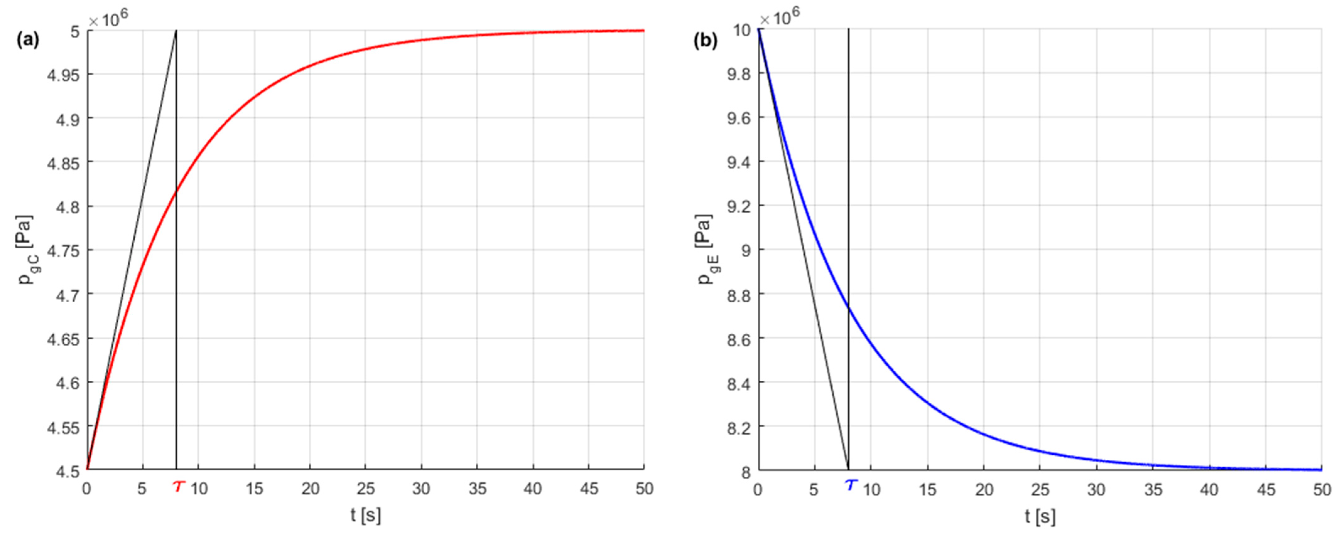
Based on the type of bladder HPA tests performed in [76], the computing parameters, a thermal time constant of τ = 8 s at the initial volume of V0 = 0.001 m3, and an initial pressure of p0 = 5 MPa were selected. In the computing example, the following pressures were adopted: p1 = 5 MPa, p1′ = 0.9 p1, p2 = 10 MPa, p2′ = 0.8 p2. Figure 16 shows the pressure–time curves of gas compression and expansion during isochoric processes.
From the ideal gas equation of state,
p g   V g = m g   R T g T g   = p g   V g m g     R
The differential equation of the state parameters follows:
T ˙ g T g =     p ˙ g p g + V ˙ g V g
  • Notes on future and frontier research methods
The use of a gas other than nitrogen, which is a diatomic gas, should be considered. However, gases other than nitrogen should not have unfavourable properties, such as diffusion through the separation and sealing elements of the HPA, sensitivity to temperature changes, or chemical affinity for the separation elements. To increase the energy capacity of the hydraulic accumulator, a gas with an atomic number greater than two should be used: the adiabat exponent κ < 1.4. The use of polyatomic gases in HPA has advantages because the more atoms the gas contains, the lower the thermal losses, and the higher the HPA efficiency, and the more atoms the gas contains, the lower the thermal load on the HPA. After a mixture of polyatomic gases is used in HPA, an even greater increase in energy capacity can be obtained. A mixture of gases is characterised by a high specific heat and low intermolecular cohesive forces. The selection of the gas mixture can optimise the energy capacity of the HPA for a specific operating range.

4.2. HPA Simulation Model

Various HPA dynamic models are used in hydraulic systems simulation studies. Hydraulic libraries with accumulator blocks are available in hydraulic simulation software Matlab/Simulink R2016a. In Matlab/Simulink, Simscape Toolbox simulation models contain a gas-charged HPA that consists of a pre-charged gas chamber and a liquid chamber. The fluid chamber is connected to a hydraulic system. Gas and fluid chambers are separated by a bladder, a piston, or any kind of diaphragm. During typical operations, the pressure in the gas chamber is equal to the pressure in the fluid chamber. The pressure at the HPA inlet depends on the pressure in the hydraulic system to which the accumulator is connected. HPA simulation models include ideal or real gas, constant and variable oil compressibility, isothermal, and adiabatic transformations. Figure 17 shows the Simscape HPA block and the HPA computation diagram.
The simulation block calculates the gas compression pressure, volume, and flow rate in the HPA based on the thermodynamics of ideal gases
p   V n = p g   V g n p = ( V g V ) n   p g
where p is the operating pressure, V is the fluid volume, pg is the gas pressure, and Vg is the gas volume.
The gas pre-charge pressure is converted to operating conditions
p g = T g + 273 293   p g 20
where pg is the gas pre-charge pressure at operating temperature, pg20 is the gas pre-charge pressure at 20 °C, and Tg is the operating temperature of the gas pre-charge.
When the HPA gas is charged and discharged, the fluid flow rate balance for the hydraulic joint is taken into account
q v a = i = 1 n q v i
where qva is the flow rate of fluid in HPA and qvi is the flow rate of fluid in the hydraulic pipe joint.
The HPA model has two operating states:
  • The active state of HPA, where gas compression is taken into account on the basis of ideal gas thermodynamics for p > pg,
  • The inactive state of HPA, where gas expansion is taken into account for ppg.
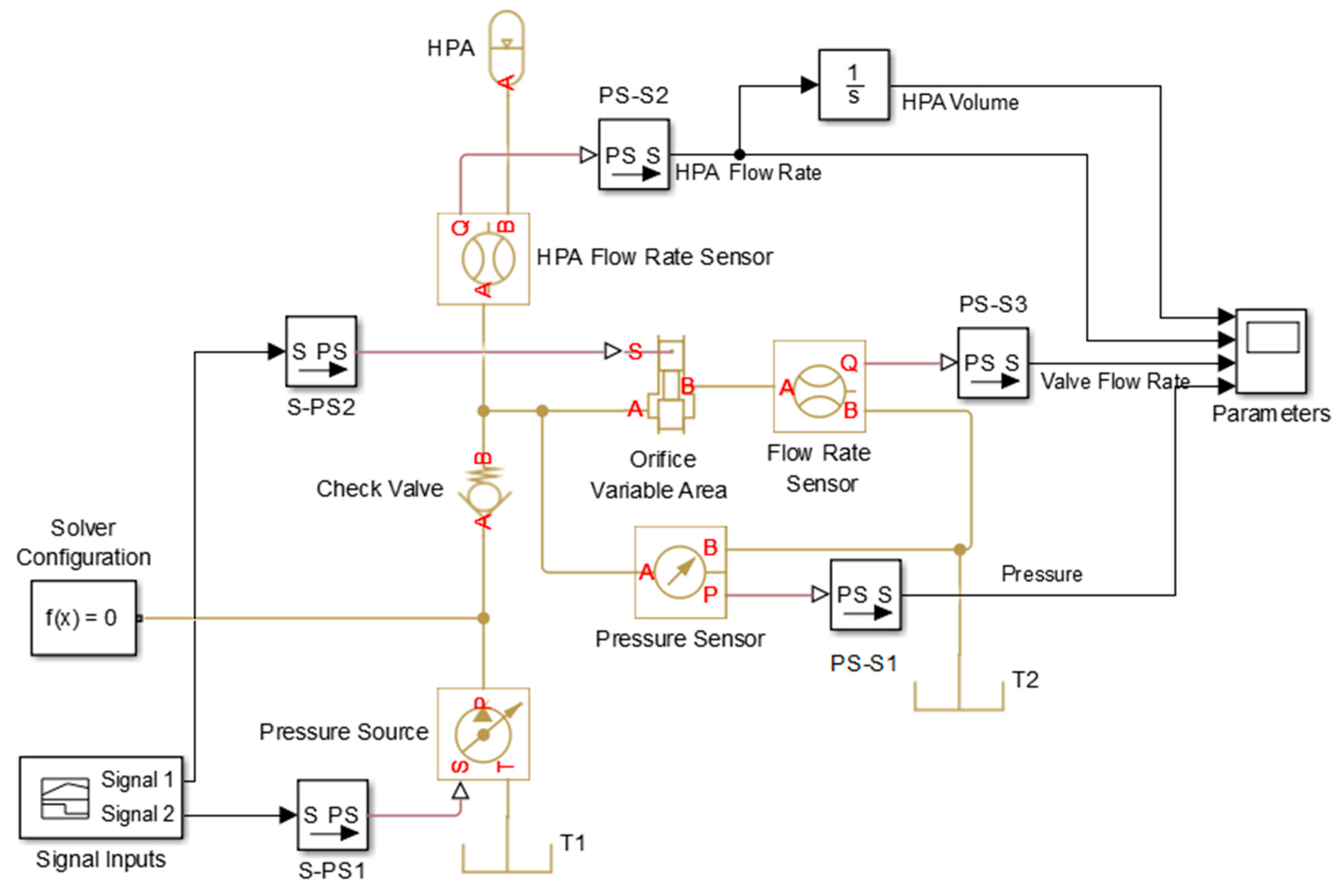
Figure 18 shows the Simscape model of the hydraulic system with an HPA block.
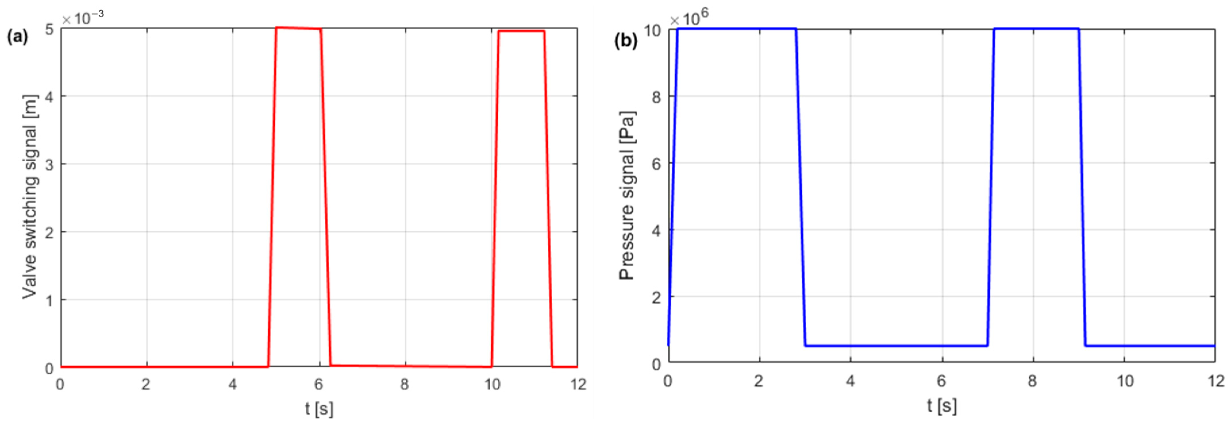
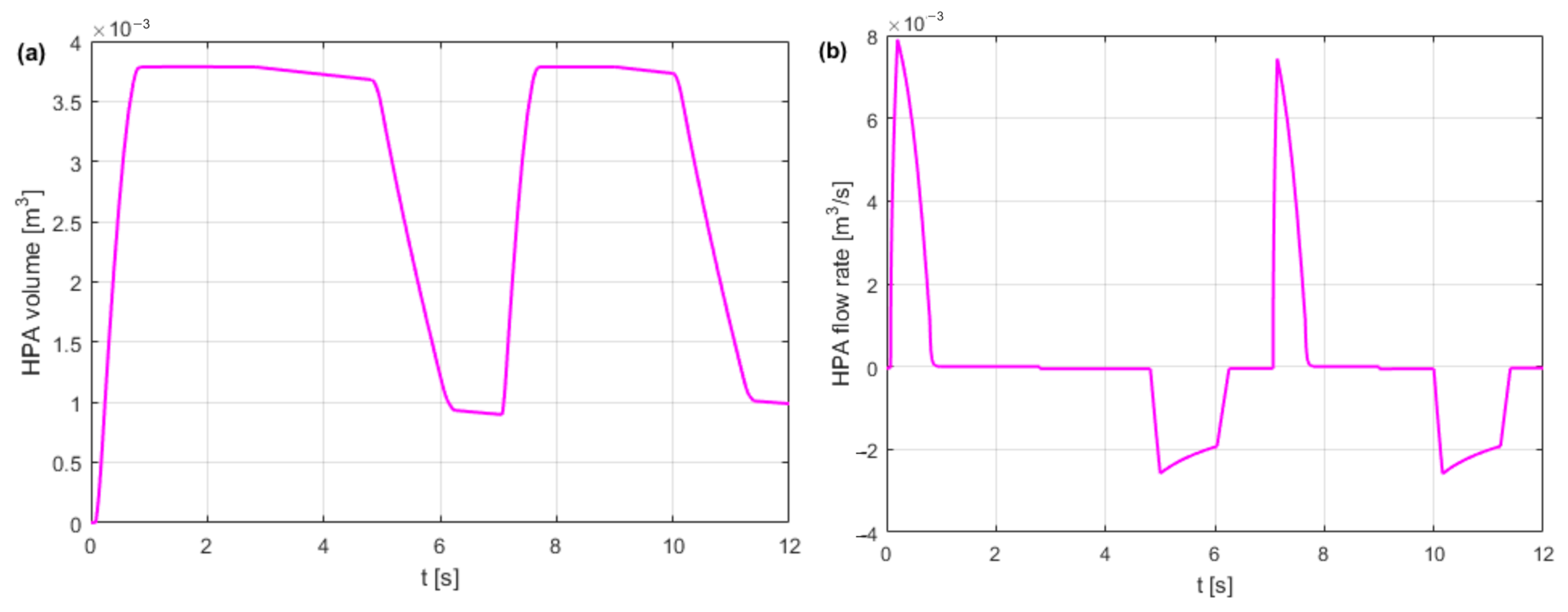
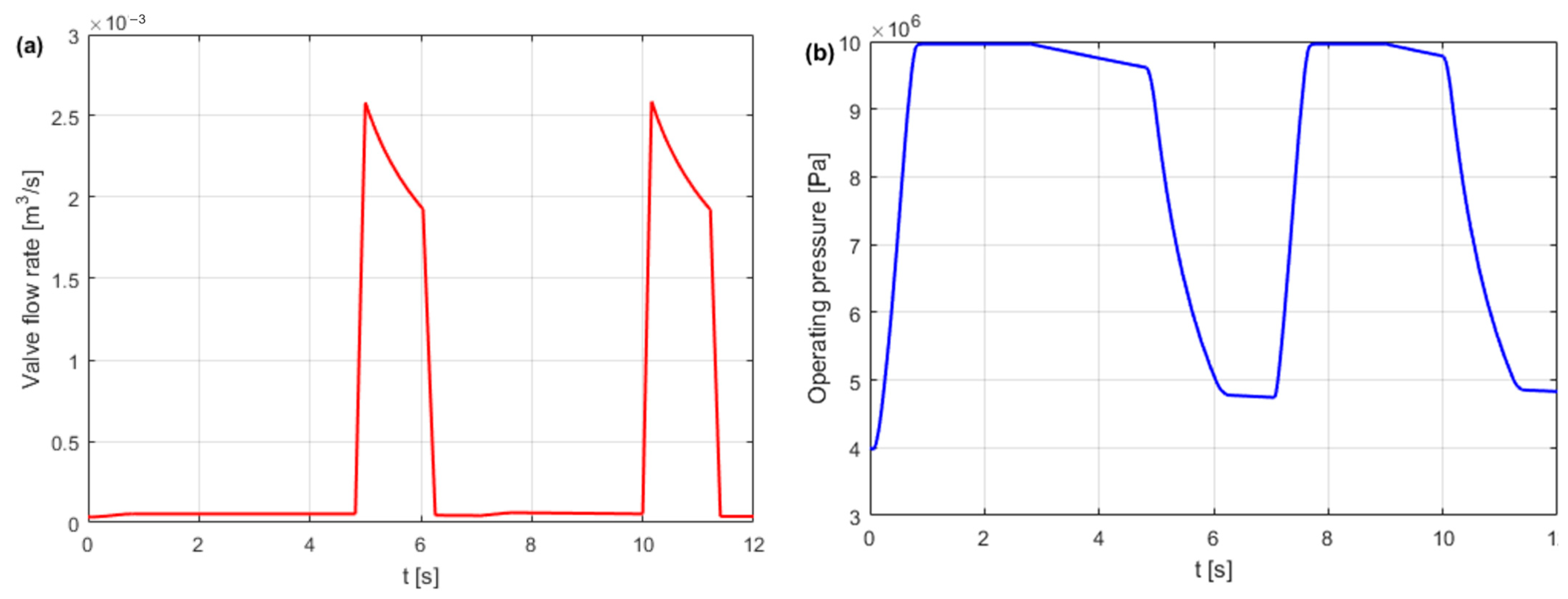
The simulated hydraulic system consists of a controlled pressure source, HPA (total volume 0.008 m3, pre-charge pressure 5 MPa) and a controlled variable flow valve. The pressure source charges the HPA when the valve is closed. The HPA discharges when the valve is open. Figure 19 shows the control signals for valve switching and pressure source switching. Figure 20 shows the change in HPA volume and flow rate in the open and closed valve states. Figure 21 shows the flow rate of the valve and the operating pressure of the hydraulic system.
  • Notes on future and frontier research methods
In simulation programs, hydraulic libraries with accumulator blocks describe the behaviour of gas compression and gas expansion. In simulation models, HPA blocks are usually used, in which the compression and expansion of the nitrogen gas are adiabatic (only true for fast processes). HPA blocks should allow for the calculation of the compression and expansion of real gas, which is more accurate, especially at high pressures. Another problem is the type of modelled hydraulic fluid. Constant compressibility, where the constant bulk modulus K = const, is usually assumed. The compressibility of the fluid dependent on pressure should be taken into account; then, K = f(p). At the same time, at low pressures, the effect of free air on the compressibility in real fluids is taken into account. Future HPA simulation models should include: construction accumulators, type of gas, fill and installation conditions, calculation of pressure gradient and compression flow, calculation of energy density, heat exchange, and transmission.

4.3. Dynamic Model of HPA

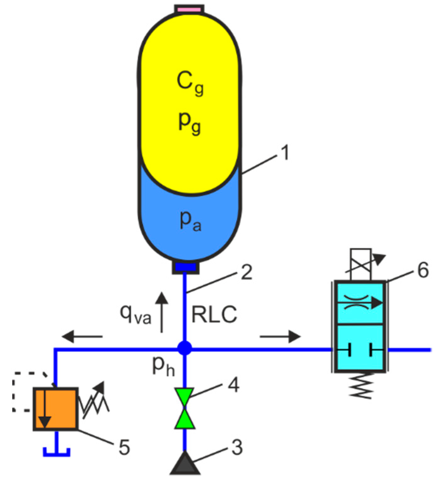
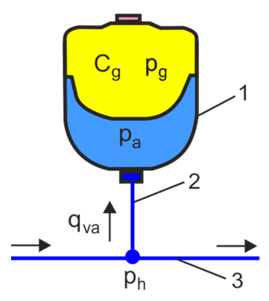
The HPA dynamic model is presented, which is used to model the processes of the filling (charging) and emptying (discharging) of the HPA. For the initial parameters, the dynamic characteristics of changes in volume, flow rate, and pressure in the HPA can be determined. Figure 22 shows a diagram of the dynamic model of the HPA connected by a tube on a branch of the hydraulic circuits.
The HPA and the connecting tube between the accumulator and the hydraulic system can be modelled by RLC lumped elements (R is the hydraulic resistance, L is the hydraulic inductance, C is the hydraulic conductance), based on the analogy between hydraulic and electronic circuits [77],
L h     d q v a d t + R h   q v a = p h p g
q v a = C g   d p g d t           d p g d t = 1 C g q v a  
where qva is the flow rate of the fluid in the HPA connecting tube, ph is the pressure of the main hydraulic line, pg is the pressure of the gas in the HPA, and pg = pa, pa is the pressure of the fluid in the HPA.
Lh is the hydraulic inductance of the connecting tube (hydraulic inductance describes the pressure difference required for a change in flow rate and is based on mass inertia):
L h     = ρ   l h A h
where ρ is the density of hydraulic oil and lh is the length of the connecting tube.
Ah is the cross-section of the connecting tube
A h =     π   d h 2 4
where dh is the diameter of the connecting tube.
Rh is the hydraulic resistance of the connecting tube determined from the Hagen–Poiseuille equation (hydraulic resistance is the flow resistance through hydraulic components):
R h   = 128   l h   ν   ρ π d h 4
where ν is the kinematic viscosity of hydraulic oil.
In the equation for the polytropic compression process, the initial HPA filling parameters are taken into account:
p i   V i n = p g   V g n p g = ( V i V g ) n   p i
After differentiation, (64) is as follows
d p g d V g = κ   p i   V i n V g n + 1
and after taking into account the gas capacitance Cg of the HPA,
C g = d V g d p g = V i n   p i ( 1 Δ V V i ) n + 1 V i n   p i = V i   K g i
where pi is the initial gas filling pressure, Vi is the initial gas filling volume, n is the polytropic exponent, and Kgi is the bulk modulus of the gas, Kgi =n pi.
The HPA dynamic model is a system of Equations (59) and (60)
{ V ˙ a = q v a q ˙ v a = 1 L h (   R h     q v a p a + p h ) p ˙ a = 1 / C g     q v a
The HPA state variable was introduced: x1 = Va fluid volume, x2 = qva fluid flow rate, x3 = pg = pa gas and fluid pressure, and u = ph input operating pressure.
The system of Equation (67) was written as the state-space model
[ x ˙ 1 x ˙ 2 x ˙ 3 ] = [ 0 1 0 0 R h / L h 1 / L h 0 1 / C g 0 ]   [ x 1 x 2 x 2 ] + [ 0 1 / L h 0 ]   u
or in matrix vector form
x ˙ ( t ) = A     x ( t ) + B     u ( t )
where
x ( t ) = [ x 1 x 2 x 2 ] ,
A = [ 0 1 0 0 R h / L h 1 / L h 0 1 / C g 0 ] ,
B   = [ 0 1 / L h 0 ]   , u ( t ) = p h .
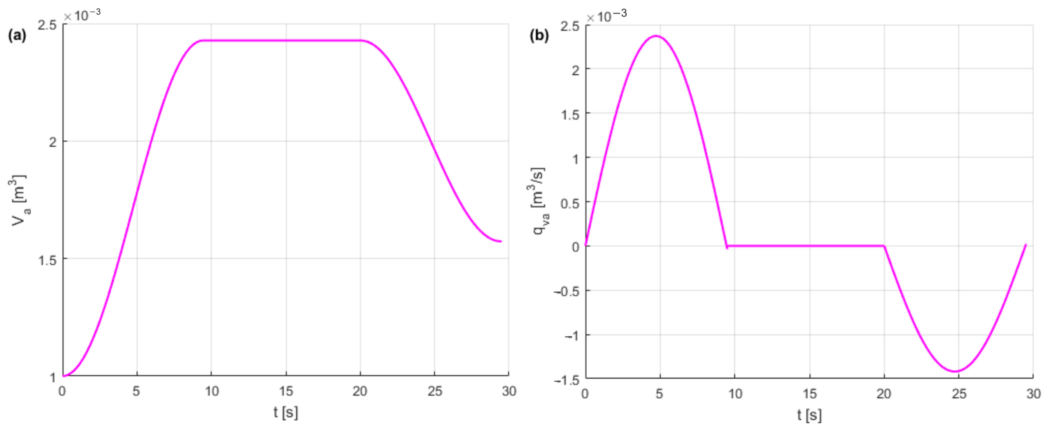
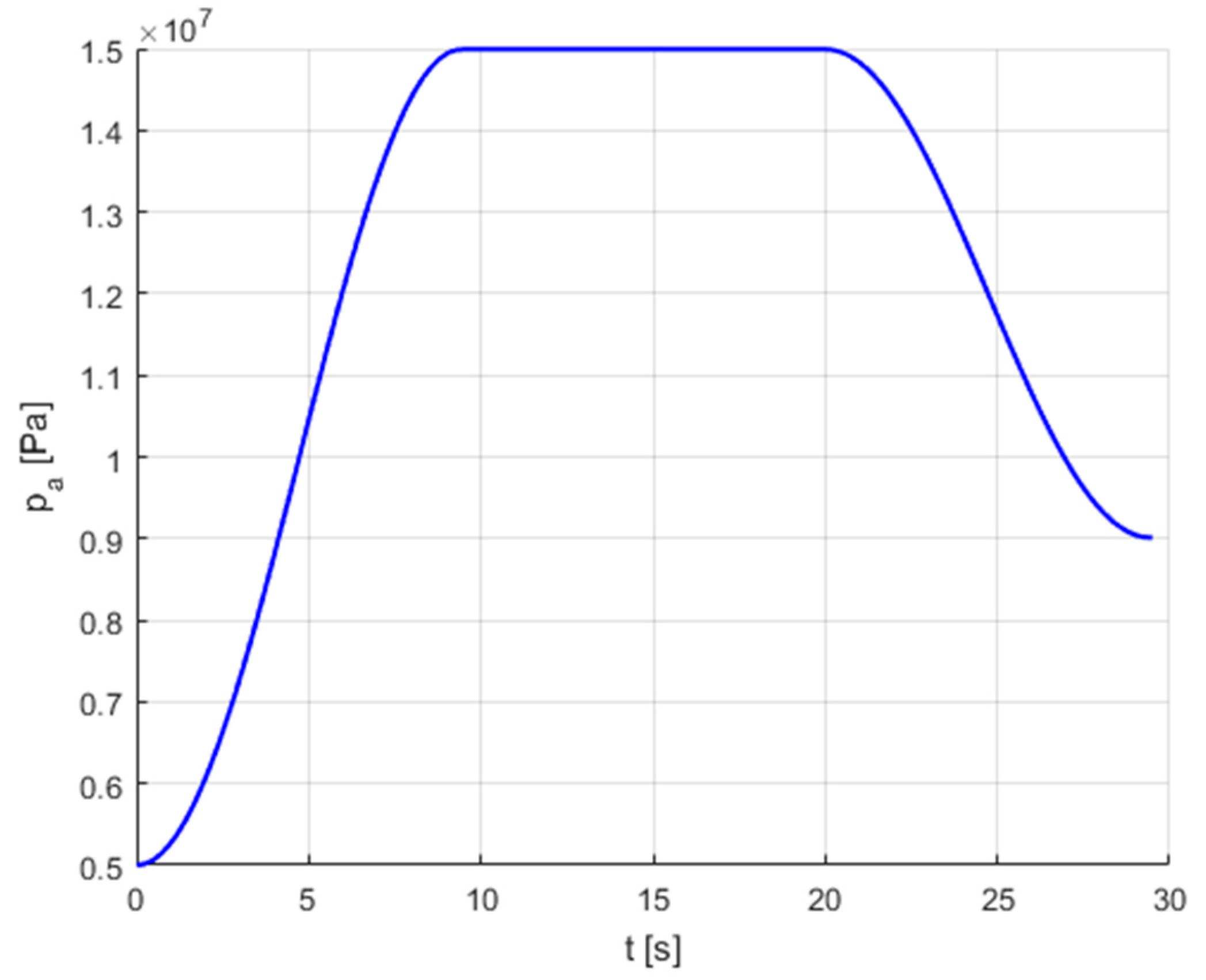
The HPA dynamic model was used to simulate the following operating states of hydraulic circuits: charging the HPA from the pressure source to 15 MPa pressure of set by the pressure relief valve; temporary stoppage; and discharge of the HPA to 9 MPa pressure after opening the throttle valve. Figure 23 shows the volume–time curve and the flow-rate–time curve of the HPA. Figure 24 shows the HPA pressure–time curve.
  • Notes on future and frontier research methods
The HPA dynamic model, critical to the modelling, simulation, and control of the hydraulic system, must meet the performance parameters depending on the requirements of the hydraulic drive system. The level of HPA dynamic models is not well defined in most technical literature. The dynamic model should take into account the HPA type. The bladder-type accumulator will provide a faster dynamic response to pressure fluctuations in the hydraulic system. The piston accumulator produces a slower dynamic response. The HPA dynamic model can be extended by the heat balance of the hydraulic drive system. This can show that appropriate coupling of the HPA to the pump, cylinder, or motor may not require the use of cooling in the hydraulic system.

4.4. Dynamic Model of HPA as a Pulsation Damper

In hydraulic systems, there is a wide spectrum of pressure pulsation frequencies. Particularly dangerous and difficult to eliminate are pressure pulsations in the range of up to 50 Hz, causing the generation of vibration and noise in hydraulic machines and equipment [78]. The best protection against the harmful effects of vibration and noise is the suppression of pressure pulsation at its source by an HPA.
Figure 25 shows a diagram of the dynamic model of a diaphragm-type HPA as a pulsation damper.
The HPA dynamic model is used according to (59), which takes the following form after differentiation:
L h     d 2 q v a d t 2 + R h   d q v a d t = d p h d t d p g d t
After substitution (66), the transformation is obtained
C g   L h     d 2 q v a d t 2 + C g   R h   d q v a d t + q v a = C g d p h d t
After the Laplace transformation, (71) takes the form of a transfer function Ga(s)
G a ( s ) = q v a ( s ) p h ( s ) = C a   s C a   L h   s 2 + C a   R h   s + 1 = C a   s 1 ω n 2   s 2 + 2   ζ   ω n   s + 1
where ωn is the natural frequency
ω n = 1 C a   L h
ζ is the damping ratio
ζ = 1 2     C a   R h   ω n
The transfer function (72) in the frequency domain has the form
G a ( j ω ) = q v a ( j ω ) p h ( j ω ) = C a   j   ω 1 ω 2 ω n 2 +   2   ζ   ω n   j ω = 1 α   [ β + j ( ω ω n ω n ω ) ]
where α and β are the constant coefficients
α = 1 C a   ω n
β = 2   ζ
Pressure pulsation in a hydraulic line can be modelled in the frequency domain using the impedance Za(), which is determined by the ratio of pressure ph and flow rate qvc
Z a ( j ω ) = 1 G a ( j ω ) = p h ( j ω ) q v a ( j ω ) = α [ β + j ( ω ω n ω n ω ) ]
From (78), the HPA impedance modulus results
| Z a ( j ω ) | = α   β 2 + ( ω ω n ω n ω ) 2
and the HPA impedance argument
arg [ Z a ( j ω ) ] = arctan ( ω ω n ω n ω ) β
Formula (79) was converted to a dimensionless form
| Z A ( j ω ) | = log ( | Z a ( j ω ) | α ) = log ( β 2 + ( ω ω n ω n ω ) 2 )
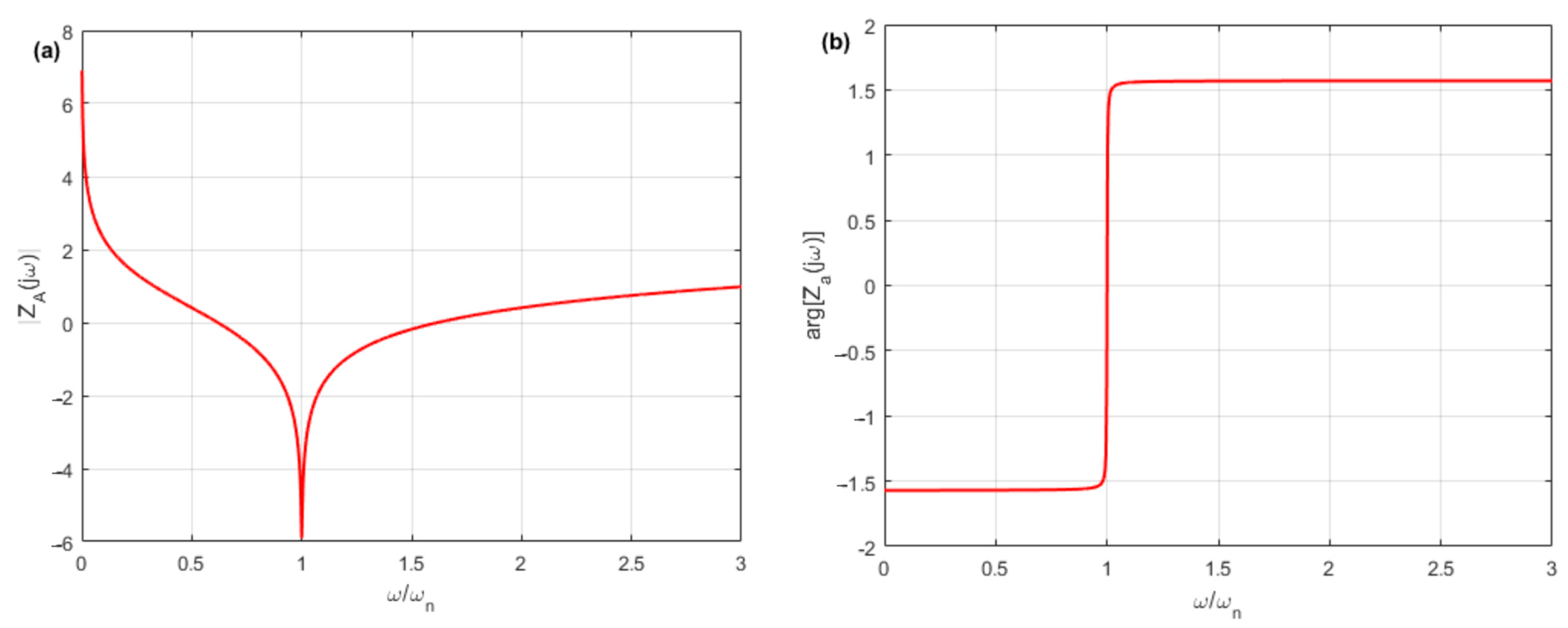
The dimensionless impedance amplitude and phase characteristics of the HPA are shown in Figure 26. Dimensionless characteristics are used to select HPA parameters that provide the lowest impedance.
Resonant vibrations should be avoided in hydraulic systems, as they cause maximum pressure pulsations that can seriously damage hydraulic components and significantly shorten their service life. To avoid resonant vibrations, the appropriate parameters of the HPA and the connecting tube should be selected.
  • Notes on future and frontier research methods
When choosing an HPA as a pulsation damper, it should be checked whether its use will improve the operation of hydraulic components, such as the uniformity of displacement and the speed of the hydraulic cylinder piston. HPAs can be used more widely to dampen pressure pulsations in a variety of demanding dynamic applications. Innovative HPA solutions are expected, e.g., lightweight composite fibres that provide pressures up to 20 MPa and save up to 40% weight compared to conventional batteries. Thus, light HPAs can be used to dampen pressure pulsations in aircraft, helicopters, and hybrid vehicles.

4.5. Dynamic Model of HPA as a Hydraulic Shock Absorber

The HPA model in the frequency domain will be considered as a damper of the hydraulic shock or water hammer that occurs during sudden shutdown of the hydraulic valve. A hydraulic shock is a pressure surge that is caused by a fluid suddenly changing velocity. A hydraulic shock is a hydraulic phenomenon that occurs when the hydraulic oil flow suddenly stops or increases. Hydraulic shock is the result of the change of kinetic energy into potential energy (positive water hammer) when the valve is closed or the change of potential energy into kinetic energy (negative water hammer) when the valve is opened.
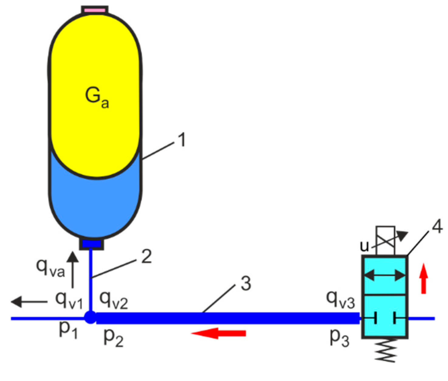
Figure 27 shows a diagram of a hydraulic transmission line (HTL) with an HPA for dynamic modelling of hydraulic shock absorption. The case of sudden closing of the hydraulic valve is considered, and then a shock wave is generated in the opposite direction in the HTL.
HTL is an element with complex dynamic behaviour. In many hydraulic systems, a simpler approach can be adopted that uses energy transformations with lumped parameters [79]. During the hydraulic shock in HIL, the kinetic energy ΔEk is transformed into potential energy ΔEp, according to the formula
Δ E k = Δ E p 1 2   L   Δ q v 2 = 1 2   C   Δ p 2 Δ p = L C   Δ q v = Z   Δ q v
where L is the hydraulic inductance of the HTL
L = ρ   l A
where ρ is the density of hydraulic fluid, l is the length of the HTL,
A is the cross-section of the area of HTL
A =     π   d 2 4
where d is the nominal diameter of the HTL,
C is the hydraulic capacitance of the HTL
C = V K = A   l K
where K is the bulk modulus of the hydraulic oil, V is the volume of the HTL, and V = A l,
Z represents the impedance of the HTL
Z = L C = ρ   a A
where a is the wave propagation speed (speed of sound in the fluid)
a   = K ρ
The model considers the HTL between the HPA connection port and the hydraulic valve.
The HPA connection port to the hydraulic pipeline is modelled using lumped parameters:
{ Δ p 1 = Δ p 2 Δ q v 1 = Δ q v a   + Δ q v 2 = { Δ p 1 = Δ p 2 Δ q v 1 = 1 Z a     Δ p 1 + Δ q v 2
The system of Equation (88) has been written in matrix vector form
[ Δ p 1 Δ q v 1 ] = [ 1 0 1 Z a 1 ]   [ Δ p 2 Δ q v 2 ] = G a [ Δ p 2 Δ q v 2 ]
where Ga is the matrix transition function of the HPA connection port
G a = [ 1 0 1 Z a 1 ]  
In the case of a long HTL, a model with distributed parameters for laminar flow is used. In the long HTL, the Newtonian fluid flow model is adopted, defined by the Navier–Stokes equation and the equation of continuity of compressible fluid flow, which, after the Laplace transformation, takes the system of equations [80]
{ Δ p 2 ( s ) = cosh ( N ( s )   T   s )     Δ p 3 ( s ) Z     N ( s )     sinh ( N ( s )   T   s )     Δ q v 3 ( s ) Δ q v 2 ( s ) = 1 Z     N ( s )     sinh ( N ( s )   T   s )     Δ p 3 ( s ) + cosh ( N ( s )   T   s )     Δ q v 3 ( s )
where N(s) is the viscosity function and T is the time constant of the HTL
T = L   C l a
In modelling the pulsating flow in the HTL, the viscous friction is neglected by assuming that the viscosity function N(s) = 1; then (91) has the form
{ Δ p 2 ( s ) = cosh (   T   s )   Δ p 3 ( s ) Z     sinh ( T   s )   Δ q v 3 ( s ) Δ q v 2 ( s ) = 1 Z         sinh ( T   s )   Δ p 3 ( s ) + cosh ( T   s )   Δ q v 3 ( s )
The system of Equation (93) has been written in matrix vector form
[ Δ p 2 Δ q v 2 ] = [ A B C D ]   [ Δ p 3 Δ q v 3 ] = G p   [ Δ p 3 Δ q v 3 ]
where A = cosh ( T s ) , B = Z   sinh ( T s ) , C = 1 Z   sinh ( T s ) , D = cosh ( T s ) .
Gp is the matrix transition function of the HTL
G p = [ A B C D ]
The considered model of the hydraulic system includes an HPA with HTL matrix transition functions
[ Δ p 1 Δ q v 1 ] = G a   G p   [ Δ p 3 Δ q v 3 ] =   [ 1 0 1 Z a 1 ]   [ A B C D ]   [ Δ p 3 Δ q v 3 ]
The propagation of the pressure shock wave at the end of the HTL was considered
Δ p 1 = Z   Δ q v 1
The solution of Equations (96) and (97) gives the ratio of pressure generated by the shock wave to damping pressure
Δ q 3 Δ q 1 = cosh ( T s ) + Z Z a   cosh ( T s ) + Z a Z   sinh ( T s )
This solution is valid for long HTLs, such as in the hydraulic pipeline of ships or water distribution pipelines. In hydraulic systems of machines and vehicles, the distances between the HPA and the valves are small. In this case, the time constant T is small, so it is reasonable to assume sinh(Ts) ≈ 0 and cosh(Ts) ≈ 1. Then, (98) will take the form
Δ q 3 Δ q 1 = 1 + Z Z a
However, after taking into account the water hammer equation, it is obtained that
Δ p 3 Δ p 1 = 1 + Z Z a
After taking into account the HPA impedance according to (79) in (100), the following relationship was obtained
Δ p 3 Δ p 1 = 1 + Z Z a = 1 + Z α   β + j   α   ( ω ω o ω o ω ) ,
which was then written in complex function notation
Δ p 3 Δ p 1 = 1 + Z   α   β   ( α   β ) 2 + α 2   ( ω ω o ω o ω ) 2 j Z   α   ( ω ω o ω o ω ) ( α   β ) 2 + α 2   ( ω ω o ω o ω ) 2
The modulus of the complex function (102) was determined as follows
| Δ p 3 Δ p 1 | = 1 + Z 2 + 2   Z   α   β ( α β ) 2 + α 2 ( ω ω o ω o ω ) 2
The absorption performance of the hydraulic shock by HPA is estimated by the following absorption index D
D = 20 log | Δ p 3 Δ p 1 | = 20 lg   1 + Z 2 + 2   Z   α   β ( α   β ) 2 + α 2   ( ω ω o ω o ω ) 2     d B
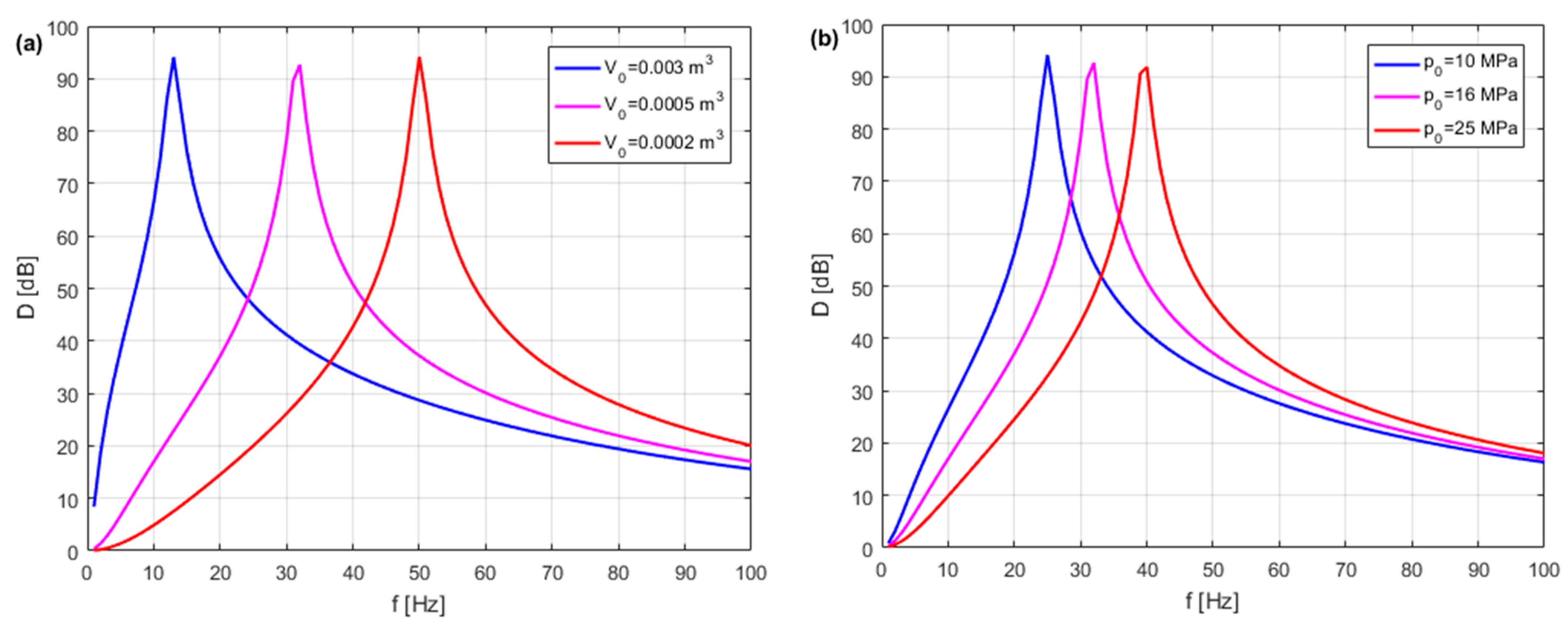
The hydraulic shock absorption efficiency index was determined for the selected volume and filling pressure of the HPA and for the selected diameters and lengths of the HPA connecting tube [81]. Figure 28 shows the diagrams of the hydraulic shock damping efficiency index D for various nominal volumes V0 and the filling pressures p0 of the HPA. Figure 29 shows the diagrams of the hydraulic shock absorption efficiency index D for various diameters dh and lengths lh of the connecting tube.
Variation in flow caused by hydraulic shock leads to fluctuations in flow and pressure in the hydraulic pipeline. Excess pressure pulsation amplitudes can cause mechanical vibrations and fatigue failures in control valves, hydraulic pipelines, and connecting elements. Hydraulic shock can affect hydraulic components, leading to their failure or even damage. When designing hydraulic systems, vibrations of the hydraulic components and the water hammer are generally not considered, although this may be justified.
  • Notes on future and frontier research methods
HPAs can be used successfully for shock pressure absorption, but they must be dimensioned for each specific application and work optimally for a relatively narrow frequency range. Hydraulic accumulators are widely used in industry because of their ability to absorb fluid shock. Researchers’ task is to design new types of HPA with better performance parameters in specific application areas.

5. HPA in Industrial Hydraulic Systems

There was a reference to research projects using HPA in industrial hydraulic systems, such as maintaining operating pressure in an industrial 80 MN open-die hydraulic forging press (HFP) and as a shock pulse absorber in the lifting and levelling module of a tracked mobile robotic bricklaying system (RBS).

5.1. Energy-Saving Hydraulic Power Supply with HPA of Industrial HFP

The main purpose of the research project [82] was to implement predictive control in the hot open-die forging process of heavy, large-size, and difficult-to-deform steel forgings in an industrial 80 MN (8000 tonnes) open-die HFP, in the largest steel plant in Poland. Figure 30 shows the elongated hot open-die process on an industrial 80 MN open-die HFP.
The hydraulic power supply system of this HFP consists of a parallel piston pump with a capacity of 2000 L/min and a set of hydraulic accumulators (HAs) of 3 × 9900 L and a pressure of 32 MPa.
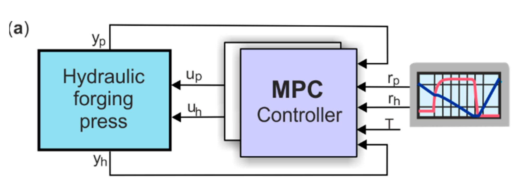
The innovative energy-saving HFP power supply reduces the consumption of electricity by the electric motor to drive the hydraulic pumps, reduces the noise emissions by the pumps, and reduces the consumption of gas to heat the forgings. Predictive control was used to predict forging forces as a function of the height of the forgings for various strain rates and forging temperatures. The control system of an HFP with an energy-saving power supply takes into account the three phases of the open-die forging processes: the drop of the upper die to make contact with the forging; the open-die forging process; the return of the upper die to the initial position. The prediction of parameters of the open-die forging process was the basis for the development of a multiple predictive control (MPC) algorithm for the industrial 80 MN open-die HFP. The MPC algorithm of the hot die forging process was developed for selected parameters, such as the predictive force of the forging and the predicted deformation of the forgings [83]. The MPC controller was implemented to control the industrial 80 MN open-die HFP, which, as a result of the actual measurement of the open-die forging control parameters, such as the displacement y(t) of the press traverse, the height h(t) of the deformed forgings, and the load pressure p(t), generates an input signal u(t) to the control valve block. The use of MPC enables the real-time switching of the two controllers based on current measured conditions and reference conditions. The MPC algorithm uses two reference parameters: the reference height rh(t) of the forgings and the reference pressure rp(t), and two measured parameters: the displacement yh(t) measured by a position transducer and pressure yp(t) measured by a pressure transducer. The temperature T of the forging is measured at the beginning of each shift draft of the open-die forging process. Figure 31 shows a block diagram of the structure of an MPC and the open-die forging parameters.
One of the main goals of this study was to reduce the energy consumption and life costs of the 80 MN industrial open-die HFP through the innovative energy-saving control of the power supply. The constant maintenance of the high pressure of an HPA during the deformation phase of the forging ensures the repeatability of the forging process and minimises the size of the forgings. As a result, a greater degree of forging deformation was achieved, and the time of forging operations, including interoperative heating, was reduced. Reducing the number of intermediate reheating operations results in a decrease in gas consumption, which increases the energy efficiency of the forging operation and is environmentally advantageous. The use of energy-saving control led to a reduction in annual energy costs of approximately EUR 218917 and a reduction in annual maintenance costs of approximately EUR 123911 [84].
The advantages of using an innovative power supply system for an industrial 80 MN open-die HFP led to a reduction in the noise emitted by pumping systems to 80 dB. Adjusting the working pressure to the forging press load contributes to supply fluid savings of up to 10% by reducing leakage through the seals of the hydraulic cylinders [85]. As a result, the following were achieved: a reduction in electricity consumption by approximately 20%, that is, by approximately 114.16 kWh/t (base value 570.95 kWh/t and target value 456.79 kWh/t of product); and a reduction in gas consumption by approximately 25%, that is, by approximately 1876.75 kWh/t (base value 7509.52 kWh/t and target value 5632.77 kWh/t of product) [86].
  • Notes on future and frontier research methods
The future target innovative power supply solution for the HFP will include two parallel power circuits: one supply circuit will contain unregulated three-piston pumps with a high capacity of 2000 L/min and a HA pressure of 32 MPa; the second supply circuit will contain regulated radial pumps with a capacity of 500 L/min and a HA pressure of 42 MPa. Such a solution is most useful for an HFP power supply of 80 MN, because it will optimise the forging process, especially in the case of heavy, difficult-to-deform forgings requiring a high forging/deformation force. The high pressure of HFP will significantly improve the qualitative and strength parameters of the forgings by obtaining a homogeneous internal structure free from discontinuities.

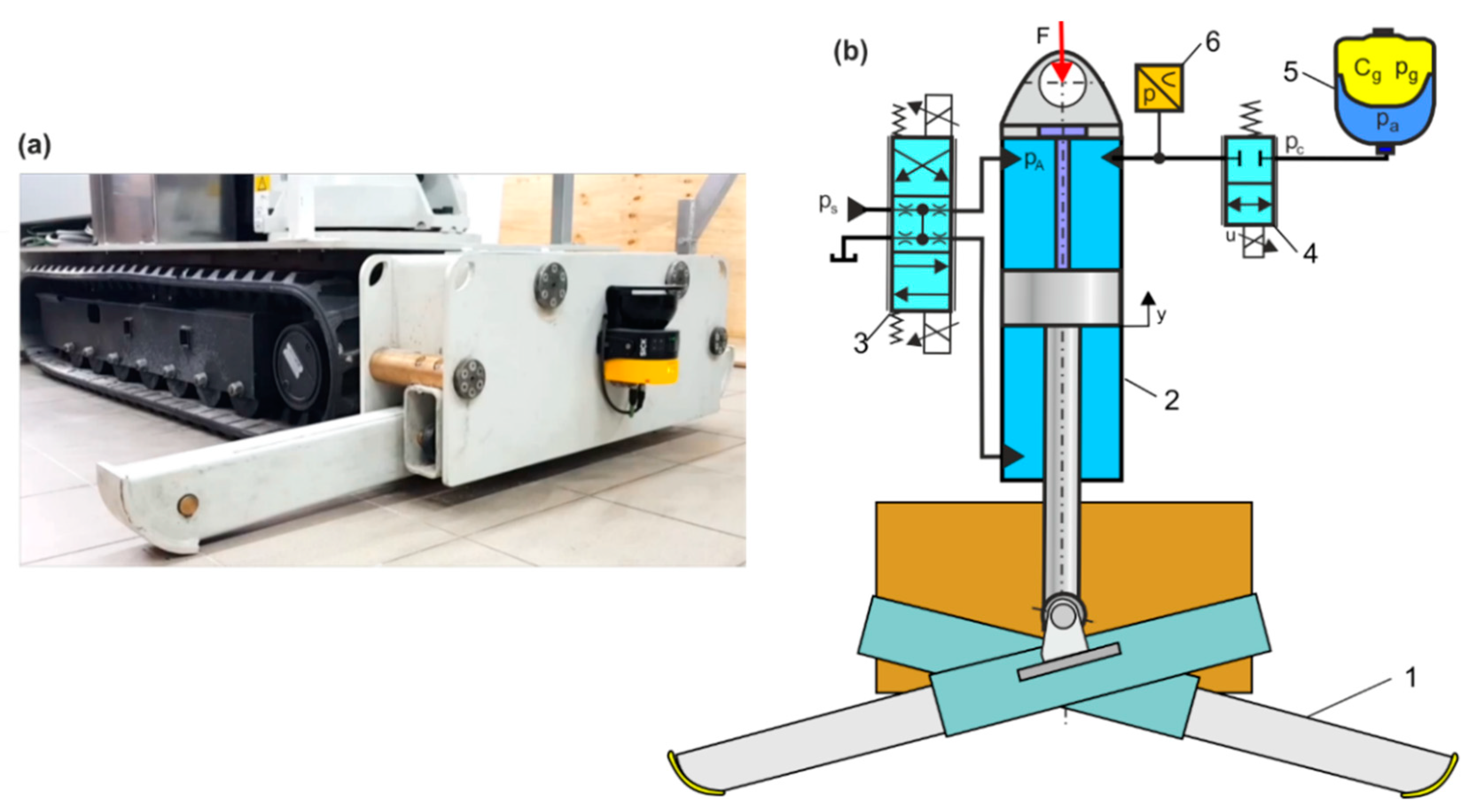
5.2. RBS Lifting and Levelling Module with HPA as a Shock Pulse Absorber

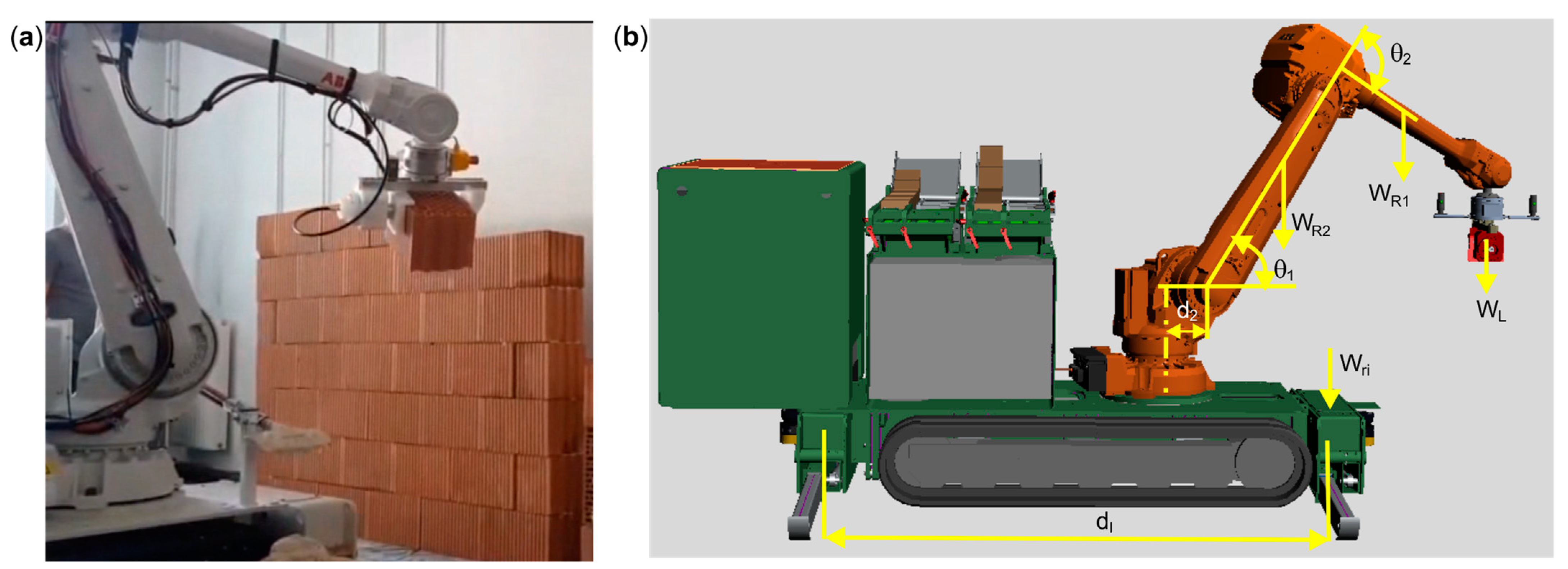
The main purpose of the research project [87] was to design, manufacture, and implement a mobile RBS, in the Polish ‘Zrobotyzowany System Murarski’ (ZSM). Mobile RBS is the first robotic brickwork system in Poland, designed primarily for the construction of facades and partitions in office and residential buildings, as well as industrial buildings. A mobile RBS has been designed and developed as an innovative solution for the construction industry to automate the heavy, labour-intensive, and burdensome masonry work traditionally performed manually by masons. The view and components of the tracked mobile RBS are shown in Figure 32.
The RBS was built with hydraulic modules, such as the hydraulic power and control modules, the hydraulic drive of the tracked undercarriage, the hydraulic the lifting–levelling module, and the hydraulic robot gripper. For RBS control, the human–machine interface (HMI) was used with the operator panel. The HMI touch panel with the start screen and control screens for the individual hydraulic modules was visually programmed to manage the mobile RBS.
Before starting the bricklaying work, the RBS travels to the bricklaying site where it is lifted, levelled, and anchored. In the bricklaying process, the robot takes the bricks from the warehouse, places the brick under the mortar applicator, and lays the brick on the wall [88]. Figure 33 shows the bricklaying robot while laying bricks and the mass load of the bricklaying robot that influences the forces acting on the hydraulic actuators of the hydraulic lifting and levelling (HLL) module.
Two HLL modules were used to stabilise the robot position during automatic bricklaying. A single HLL module is constructed using two hydraulically lifting support legs mounted on a cross system. Levelling occurs in two stages: maximum extension of the supporting legs by means of short-stroke actuators and lifting and levelling of the supporting legs by means of lifting actuators. In the first stage, the actuators extend the supporting legs without external load until they come into contact with the ground. In the second stage, the lifting actuators press the supporting legs until the tracked undercarriage is raised to the required height. Once levelled, the legs are mechanically locked [89,90]. The operation of a bricklaying robot consisting of placing bricks of different weights in a large work space causes a variable dynamic shock transmitted on the HLL modules. Dynamic shock loads cause mechanical and hydraulic components to vibrate, resulting in an incorrect trajectory of the bricklaying robot. As a result of the shock loading of the RBS, pressure shock pulses are generated in the HLL cylinders. The pressure shock pulse in the HLL cylinders can manifest itself when the robot arm is ‘buckling’. To prevent these unfavourable phenomena from occurring in the HLL modules, we used an HPA as a shock pulse absorber. Figure 34 shows the view of the HLL module and the diagram of the HLL with an HPA as a shock pulse absorber [91].
A dynamic analysis of the HLL module with and without HPA was carried out. Figure 35 compares the dynamic responses of the undamped and damped shock pressure pL(t).
The efficacy of HPA shock pulse absorption was analysed for different shock forces, shock forces with irregular course, and shock forces with an instantaneous rise and fall. For the HLL module with the HPA, a control system was used that will cause a rapid response of the damping valve and thus effective continuous control of the shock pulse absorption.
  • Notes on future and frontier research methods
In order to fully assess the path accuracy of the bricklaying robot, it is necessary to take into account the impact of the RBS operating parameters on the HLL, including the mapping of the robot’s dynamic behaviour at individual points in the bricklaying process. The goal of further research is to provide HPA as a shock pressure damper that responds quickly, dampens the pressure rise, and dissipates the energy of the input shock forces. The design of HPA hydraulic circuits should include adjustable damping valves to dissipate shock energy. Active damping control should be considered.

6. Future Directions of Development and Challenges

Global energy efficiency challenges are related to energy storage technology. Hydro-pneumatic energy storage from wind, photovoltaics, and sea waves is under development. The technology of hydro-pneumatic energy storage is based on a hydro-pneumatic liquid piston concept, whereby electricity is stored by using it to pump seawater into a closed chamber and compress a fixed volume of pre-charged air. The energy can then be recovered by expanding the air and pushing the water back through the hydraulic turbine generator. Energy storage in conventional nitrogen HPAs is not yet commercial, but solving this problem is a matter of time. HPA is widely used in various hydraulic transmission systems (HTS) to improve system efficiency, such as reducing installed power.
The future direction of innovative HPA solutions is explained in the subsequent publications reviewed. HPA has two main drawbacks: limited energy storage capacity and passive operation. To overcome these problems, a novel controllable accumulator with a higher energy storage capacity is proposed, comprising a piston accumulator, a gas chamber regulator, and several control valves [92]. This novel accumulator overcomes the limitation of energy storage and is helpful when used in more powerful machines. Conventional hydraulic accumulators suffer limitations; the hydraulic system pressure varies with the amount of energy stored, and the energy density is significantly lower than that of other energy sources. In [93], a novel hydraulic accumulator is presented that uses a piston with an area that varies with stroke to maintain constant pressure on the hydraulic system while the gas pressure changes. In [94], a combined piston-type accumulator is proposed with a relatively steady pressure property. The gas chamber and the fluid chamber are separated by a cam mechanism. By using the non-linear property of the cam mechanism, the non-linear relationship between the pressure and the gas volume can be set. Therefore, the fluid pressure can be maintained in a relatively steady range. In [95], it was proposed to reduce the volume of the HPA without changing its stiffness by using highly porous adsorbents, such as activated carbon. Gas molecules adhere to the surface of the adsorbents; thus, changing the volume of the gas does not affect the pressure. In [96], the basis for the novel design of thermohydraulic generators with single regime operation was presented. The thermal–hydraulic generator in a single-regime running is the main part of the new thermal–hydraulic propulsion systems. The new thermal–hydraulic system includes a thermal–hydraulic generator, an HPA, and a hydraulic motor. In [97], the influence of the high- and low-pressure HPA design parameters on the stiffness coefficient, natural frequency, and degree of damping of a hydro-pneumatic tensioner was analysed, which is a necessary device to ensure the safety of a vertically stressed vertical pipe in offshore oil and gas extraction equipment. Using the shape-memory effect of nitinol, a type of shape-memory alloy (SMA), an innovative SMA-actuated hydraulic accumulator prototype was developed and successfully tested at the Smart Materials and Structure Laboratory at the University of Houston [98]. The SMA-actuated hydraulic accumulator is used for a variety of control and actuation operations, such as closing the rams of the blowout preventers and controlling the subsea valves on the sea floor.
HPA dredging is a key innovation area in the construction industry. According to GlobalData [99], there are 30+ companies, including technology providers, established construction companies, and start-ups, engaged in the development and application of HPA dredging. Freudenberg Sealing Technologies has developed an innovative lightweight piston accumulator for hydraulic systems in hybrid powertrains [100]. Developers have succeeded in significantly reducing the weight of high-pressure and low-pressure piston accumulators, thanks to a special construction design and a new joining technology. The HPA manufacturing process is particularly important to ensure the stability of the HTS under high pressure. In [101], a technology for the hot spinning process of the HPA shell was proposed. A Johnson–Cook constitutive model of the HPA shell material made of 34CrMo4 alloy steel was developed, the parameters of which were obtained experimentally.

7. Conclusions

The focus of this review is on the computational, simulation, and dynamic models of HPA and their selection for various energy-efficient hydraulic systems. Computational models are useful for the selection of HPAs as energy storage, pressure maintainers, compensation for leakage and volume changes, and safety devices. HPA simulation and dynamic models are used to study dynamic phenomena in the time and frequency domains that occur in different hydraulic systems.
All HPA computing and dynamic models and simulation results produced in Matlab of MathWorks are the original solutions of the authors, which have no counterparts in other publications. The models and results presented in the manuscript will contribute to expanding knowledge about HPA and their importance in the design of various hydraulic systems.
A new approach to HPA computing and modelling is the adoption of the polytropic compression and expansion processes of the gas and a definition of an approximate polytropic exponent. The proposed approximate polytropic exponent of a real gas has practical applications because the equations of the polytropic processes of the ideal gas can be used when selecting HPA. In HPA selection, the PV thermodynamic cycle was taken into account, in which there are the isochoric and polytropic processes of an ideal gas.
The original approach to HPA dynamic modelling is based on the RLC model, where R and L are the resistance and impedance of the connecting tube and C is the gas capacitance in HPA. This model was used to determine the HPA frequency characteristics as a pulsation damper and shock pulse damper. In HTL modelling for laminar flow, models with lumped and distributed parameters were included.
Reference is made to examples of research projects that use HPA in industrial 80 MN open-die HFPs. The use of the energy-saving control of a hydraulic power unit with an HPA for maintaining operating pressure has led to the achievement of accurate forging geometry, minimised material allowances, and reduced the material consumption of production. The use of HPA as a shock pulse absorber in a mobile robotic RBS was important for stabilising the position of the robot, which determines the accuracy of the robot’s trajectory and the quality of the masonry work performed.
This review is expected to provide the reader with a comprehensive and clear understanding of the importance of HPA modelling and simulation, which will be an important reference point for further research and potential applications. In the future, HPA maturation innovations may be disruptive in the fields of energy regeneration and conversion (ERC), energy storage technology (EST), and hydraulic transmission system (HTS).

Author Contributions

Conceptualisation, R.D.; methodology, R.D.; software, R.D.; validation, P.W.; formal analysis, R.D.; investigation, J.T.; resources, R.D.; data curation, R.D.; writing—original draft preparation, R.D.; writing—review and editing, R.D.; visualisation, R.D.; supervision, R.D.; project administration, J.T. and P.W. All authors have read and agreed to the published version of the manuscript.

Funding

This research received no external funding.

Data Availability Statement

Not applicable.

Conflicts of Interest

The author declares no conflict of interest.

References

  1. EN 52021PC0558; Proposition for a Directive of the European Parliament and of the Council on Energy Efficiency. European Commission: Brussels, Belgium, 2021. Available online: https://eur-lex.europa.eu/legal-content/EN/TXT/?uri=CELEX:52021PC0558) (accessed on 14 July 2021).
  2. Sikora, A. European Green Deal–legal and financial challenges of climate change. ERA Forum 2021, 21, 681–697. [Google Scholar] [CrossRef]
  3. EU 2019/1781; UE Commission of 1 October 2019 Laying Down Ecodesign Requirements for Electric Motors and Variable-Speed Drives. European Commission: Brussels, Belgium, 2019. Available online: http://data.europa.eu/eli/reg/2019/1781/oj (accessed on 1 October 2019).
  4. Pantano, S. Super-efficient equipment and appliances deployment (SEAD) initiative. In Proceedings of the IEEJS&L Symposium, Tokyo, Japan, 10 February 2012. [Google Scholar]
  5. Globe Newswire. Hydraulic Power Unit Global Market Report 2023. Available online: https://www.globenewswire.com/news-release/2023/08/04/2719228/0/en/Hydraulic-Power-Unit-Global-Market-Report-2023.html (accessed on 4 August 2023).
  6. International Energy Agency. Tracking Clean Energy Progress 2023. Available online: https://translate.google.pl/?hl=pl&sl=en&tl=pl&text=Tracking%20Clean%20Energy%20Progress%202023%0A.&op=translate (accessed on 1 July 2023).
  7. Demonstrating Lower Emissions and Higher Efficiency through Innovative Hydraulic Systems in Demolition Machinery; LIFE20 ENV/SK/000392; Idraulica Sighinolfi Albano: Nonantola MO, Italy, 2021; Available online: https://webgate.ec.europa.eu/life/publicWebsite/project/details/5612 (accessed on 1 September 2021).
  8. Gerke, B.F.; McNeil, M.A.; Tu, T. The International Database of Efficient Appliances (IDEA): A new tool to support appliance energy-efficiency deployment. App. Energy 2017, 205, 453–464. [Google Scholar] [CrossRef]
  9. Rydberg, K.-E. Energy efficient hydraulics–System solutions for loss minimization. In Proceedings of the National Conference on Fluid Power, Linköping University, Linköping, Sweden, 16–17 March 2015; pp. 1–9. [Google Scholar]
  10. Mahato, A.C.; Ghoshal, S.K. Energy-saving strategies on power hydraulic system: An overview. Proc. Inst. Mech. Eng. Part I J. Syst. Control Eng. 2021, 235, 147–169. [Google Scholar] [CrossRef]
  11. Baghestan, K.; Rezaei, S.M.; Talebi, H.A.; Zareinejad, M. An energy-saving nonlinear position control strategy for electro-hydraulic servo systems. ISA Trans. 2015, 59, 268–279. [Google Scholar] [CrossRef]
  12. Ho, T.H.; Le, T.D. Development and evaluation of energy-saving electro-hydraulic actuator. Actuators 2021, 10, 302. [Google Scholar] [CrossRef]
  13. Schmidt, L.; Hansen, K.V. Electro-hydraulic variable-speed drive networks—Ideas, perspectives, and energy saving potentials. Energies 2022, 15, 1228. [Google Scholar] [CrossRef]
  14. Pratumsuwan, P.; Hutamarn, S.; Watcharin, P.-N. Energy saving in electro-hydraulic system using a MIMO fuzzy controller. Energy Res. Power Eng. 2014, 622–623, 75–79. [Google Scholar]
  15. Padovani, D.; Fresia, P.; Rundo, M.; Altare, G. Downsizing the electric machines of energy-efficient electro-hydraulic drives for mobile hydraulics. J. Phys. Conf. Ser. 2022, 2385, 012028. [Google Scholar] [CrossRef]
  16. Wrat, G.; Bhola, M.; Ranjan, P.; Mishra, S.K.; Das, J. Energy saving and Fuzzy-PID position control of electro-hydraulic system by leakage compensation through proportional flow control valve. ISA Trans. 2020, 101, 269–280. [Google Scholar] [CrossRef]
  17. Kędzia, K.A. Method of determining optimal parameters for the secondary energy source of a multisource hydrostatic drive system in machines working in closed spaces. Energies 2022, 15, 5132. [Google Scholar] [CrossRef]
  18. Li, J.; Zhao, J.; Zhang, X. A novel energy recovery system integrating flywheel and flow regeneration for a hydraulic excavator boom system. Energies 2020, 13, 315. [Google Scholar] [CrossRef]
  19. Padovani, D.; Rundo, M.; Altare, G. The working hydraulics of valve-controlled mobile machines: Classification and review. J. Dyn. Syst. Meas. Control 2020, 142, 070801. [Google Scholar] [CrossRef]
  20. Sobczyk, A. Improvement of Hydraulic Energy Efficiency Be Means of Energy Recuperations; Monograph 403; Cracow University of Technology: Cracow, Poland, 2011. [Google Scholar]
  21. Casoli, P.; Riccò, L.; Campanini, F.; Bedotti, A. Hydraulic hybrid excavator—Mathematical model validation and energy analysis. Energies 2016, 9, 1002. [Google Scholar] [CrossRef]
  22. Cho, S.H.; Noskievič, P. Position tracking control with load-sensing for energy-saving valve-controlled cylinder system. J. Mech. Sci. Technol. 2012, 26, 617–625. [Google Scholar] [CrossRef]
  23. Quan, Z.; Ge, L.; Weil, Z.; Li, Y.W.; Quan, L. A survey of powertrain technologies for energy-efficient heavy-duty machinery. Proc. IEEE 2021, 109, 279–308. [Google Scholar] [CrossRef]
  24. Casoli, P.; Scolari, F.; Vescovini, C.M.; Rundo, M. Energy comparison between a load sensing system and electro-hydraulic solutions applied to a 9-ton excavator. Energies 2022, 15, 2583. [Google Scholar] [CrossRef]
  25. Lin, T.; Wang, Q.; Hu, B.; Gong, W. Development of hybrid powered hydraulic construction machinery. Autom. Constr. 2010, 19, 11–19. [Google Scholar] [CrossRef]
  26. Bedotti, A.; Pastori, M.; Casoli, P. Modelling and energy comparison of system layouts for a hydraulic excavator. Energy Procedia 2018, 148, 26–33. [Google Scholar] [CrossRef]
  27. Wang, H.; Wang, Q.; Hu, B. A review of developments in energy storage systems for hybrid excavators. Autom. Constr. 2017, 80, 1–10. [Google Scholar] [CrossRef]
  28. Yang, H.; Sun, W.; Xu, B. New investigation in energy regeneration of hydraulic elevators. IEEE/ASME Trans. Mechatron. 2007, 12, 519–526. [Google Scholar] [CrossRef]
  29. ISO 4126-1:2013; Safety Devices for Protection against Excessive Pressure—Part 1: Safety Valves. ISO: Geneva, Switzerland, 2013. Available online: https://www.iso.org/obp/ui/#iso:std:iso:4126:-1:ed-3:v1:en (accessed on 16 July 2013).
  30. Pressure Equipment Directive (PED) 2014/68/EU; European Parliament and of the Council: Brussels, Belgium, 2014; Available online: http://publications.europa.eu/resource/cellar/1ddec7ca-0e96-11e4-a7d0-01aa75ed71a1.0006.03/DOC_1 (accessed on 15 May 2014).
  31. HYDAC. Safety and Shut-Off Block; Hydac International: Sulzbach/Saar, Germany, 2013. [Google Scholar]
  32. ORELL. Hydraulic Accumulators Application; ORELL Tec AG: Düdingen, Switzerland, 2015. [Google Scholar]
  33. HYDRO LEDUC. Hydraulic Accumulators; HYDRO LEDUC: Azerailles, France, 2018. [Google Scholar]
  34. HANSA. Hydraulic Accumulators; HANSA TMP: Modena, Italy, 2010. [Google Scholar]
  35. HANSA-FLEX. Hydraulic Accumulators; HANS-FLEX AG: Bremen, Germany, 2020. [Google Scholar]
  36. FOX. Hydraulic Accumulators; FOX s.r.l.: Milano, Italy, 2020. [Google Scholar]
  37. FPE. Hydraulic Accumulators; EPE Italiana s.r.l.: Cologno Monzese, Italy, 2022. [Google Scholar]
  38. HYDAC. Hydraulic Accumulators; Hydac International: Sulzbach/Saar, Germany, 2021. [Google Scholar]
  39. Ripke, R. Hydraulic Accumulators: Learn How Hydraulic Accumulators Work: Hydraulic Accumulators How They Work; Amazon Digital Services LLC.: Seattle, WA, USA, 2021. [Google Scholar]
  40. Ibbetson, W. Accumulator Charging-Maintenance and Repair; Read Books Ltd.: Redditch, England, 2010. [Google Scholar]
  41. Nisters, C.; Bauer, F.; Brocker, M. Condition Monitoring Systems for Hydraulic Accumulators–Improvements in Efficiency, Productivity and Quality; Technische Universität Dresden: Dresden, Germany, 2020. [Google Scholar]
  42. Dindorf, R.; Wos, P. Development of Hydraulic Power Systems; Monograph M72; Kielce University of Technology: Kielce, Poland, 2016. [Google Scholar]
  43. He, X.; Xiaoa, G.; Hua, B.; Tana, L.; Tanga, H.; Hea, S.; Hea, Z. The applications of energy regeneration and conversion technologies based on hydraulic transmission systems: A review. Energy Convers. Manag. 2020, 205, 112413. [Google Scholar] [CrossRef]
  44. Rydberg, K.-E. Energy efficient hydraulic hybrid drives. In Proceedings of the 11th Scandinavian International Conference on Fluid Power, SICFP’09, Linköping, Sweden, 2–4 June 2009. [Google Scholar]
  45. Man, Z.; Ding, F.; Ding, C.; Liu, S. Study of an energy regeneration system with accumulator for hydraulic impulse testing equipment. Stroj. Vestn.–J. Mech. Eng. 2015, 61, 196–206. [Google Scholar] [CrossRef]
  46. Ramesh, S.; Denis Ashok, S.; Nagaraj, S.; Adithyakumar, C.R.; Lohith, M.; Reddy, K.; Naulakha, K.N. Design of an energy efficient hydraulic regenerative circuit. IOP Conf. Ser. Mater. Sci. Eng. 2018, 310, 012042. [Google Scholar] [CrossRef]
  47. Lin, T.; Chen, Q.; Ren, H.; Zhao, Y.; Miao, C.; Fu, S.; Chen, Q. Energy Regeneration Hydraulic System via a Relief Valve with Energy Regeneration Unit. Appl. Sci. 2017, 7, 613. [Google Scholar] [CrossRef]
  48. Klapka, M.; Nevrly, J.; Panacek, T. Experimental rig for simulation of hydromechanical system with energy regeneration. Eng. Mech. 2014, 21, 305–309. [Google Scholar]
  49. Ho, T.H.; Ahn, K.K. Modeling and simulation of hydrostatic transmission system with energy regeneration using hydraulic accumulator. J. Mech. Sci. Technol. 2010, 24, 1163–1175. [Google Scholar] [CrossRef]
  50. Minav, T.; Henri Hänninen, H.; Sinkkonen, A.; Laurila, L.; Pyrhonen, J. Electric or hydraulic energy recovery systems in a reach truck—A comparison. Stroj. Vestn. J. Mech. Eng. 2014, 60, 232–240. [Google Scholar] [CrossRef]
  51. Leon-Quiroga, J.; Newell, B.; Krishnamurthy, M.; Gonzalez-Mancera, A.; Garcia-Bravo, J. Energy efficiency comparison of hydraulic accumulators and ultracapacitors. Energies 2020, 13, 1632. [Google Scholar] [CrossRef]
  52. Silva, M. HRB–Hydrostatic Regenerative Braking System. The Hydraulic Hybrid Drive from Bosch Rexroth; Bosch Rexroth AG: Elchingen, Germany, 2020. [Google Scholar]
  53. Baseley, S.; Ehret, C.; Greif, E.; Kliffken, M. Hydraulic Hybrid Systems for Commercial Vehicles; SAE 2007 Commercial Vehicle Engineering Congress & Exhibition; Technical Paper 2007-01-4150; SAE International: Warrendale, PA, USA, 2007. [Google Scholar]
  54. Johnston, C. High-pressure hybrids: Fuel-efficient hydraulic vehicles come of age. Sci. Am. 2010, 303, 1–5. [Google Scholar]
  55. PSA Peugeot Citroen. Hybrid Air, An Innovative Petrol Full Hybrid Solution for the Car of the Future. Available online: https://www.groupe-psa.com/en/newsroom/automotive-innovation/hybrid-air (accessed on 18 March 2023).
  56. Feng, B.; Xu, H.; Wang, A.; Gao, L.; Bi, Y.; Zhang, X. A comprehensive review of energy regeneration and conversion technologies based on mechanical–electric–hydraulic hybrid energy storage systems in vehicles. Appl. Sci. 2023, 13, 4152. [Google Scholar] [CrossRef]
  57. Zhou, H.; Xu, Z.; Liu, L.; Liu, D.; Zhang, L. Design and validation of a novel hydraulic hybrid vehicle with wheel motors. Sci. Prog. 2020, 103, 0036850419878024. [Google Scholar] [CrossRef] [PubMed]
  58. Masser, R.; Hoffmann, K.H. Endoreversible modeling of a hydraulic recuperation system. Entropy 2020, 22, 383. [Google Scholar] [CrossRef] [PubMed]
  59. Xu, L.; He, X.; Shen, X. Improving energy recovery rate of the regenerative braking system by optimization of influencing factors. Appl. Sci. 2019, 9, 3807. [Google Scholar] [CrossRef]
  60. Yue, D.; Gao, H.; Liu, Z.; Wei, L.; Liu, Y.; Zuo, X. Potential energy recovery and direct reuse system of hydraulic hybrid excavators based on the digital pump. Energies 2023, 16, 5229. [Google Scholar] [CrossRef]
  61. Chen, J.-S. Energy efficiency comparison between hydraulic hybrid and hybrid electric vehicles. Energies 2015, 8, 4697–4723. [Google Scholar] [CrossRef]
  62. ASPlight. Tools for Optimal Calculation of the Hydraulic Accumulator. Available online: https://www.hydac.com/en/online-tools/asplight (accessed on 18 March 2023).
  63. HYDAC. Sizing Accumulators; Hydac International: Sulzbach/Saar, Germany, 2013. [Google Scholar]
  64. Wu, Z.; Xiang, Y.; Li, M.; Iqbal, M.Y.; Xu, G. Investigation of accumulator main parameters of hydraulic excitation system. J. Coast. Res. 2019, 93, 613–622. [Google Scholar] [CrossRef]
  65. Pfeffer, A.; Glück, T.; Kemmetmüller, W.; Kugi, A. Mathematical modelling of a hydraulic accumulator for hydraulic hybrid drives. Math. Comp. Model. Dyn. Syst. 2016, 22, 397–411. [Google Scholar] [CrossRef]
  66. Mamcic, S.; Bogdevicius, M. Simulation of dynamic processes in hydraulic accumulators. Transport 2010, 25, 215–221. [Google Scholar] [CrossRef]
  67. Kumar, A.; Das, J.; Dasgupta, K.; Barnwal, M.-K. Effect of hydraulic accumulator on pressure surge of a hydrostatic transmission system. J. Inst. Eng. India Ser. 2018, 99, 169–174. [Google Scholar] [CrossRef]
  68. Petric, J. Modeling of hydro-pneumatic energy storage system. In Proceedings of the 8th EUROSIM Congress on Modelling and Simulation, Cardiff, UK, 10–13 September 2013; pp. 214–219. [Google Scholar]
  69. Li, H.; Zhu, T.; Xin, Y. Modeling and simulation of a hydro-pneumatic accumulator system for hybrid air development. Appl. Mech. Mat. 2014, 733, 763–767. [Google Scholar]
  70. Rotthäuser, S. Verfahren zur Berechnung and Untersuchung Hydropneumatischer Speicher. Ph.D. Thesis, Technische Hochschule Aachen, Aachen, Germany, 1993. [Google Scholar]
  71. Miyashita, S.; Zhang, S.; Kazushi Sanada, K. A study on a mathematical model of gas in accumulator using van der Waals equation. In Proceedings of the 15th Scandinavian International Conference on Fluid Power, SICFP’17, Linköping, Sweden, 7–9 June 2017; pp. 237–242. [Google Scholar]
  72. Gao, L.; Wang, D.; Jin, C.; Yi, T. Modelling and performance analysis of cyclic hydro-pneumatic energy storage system considering the thermodynamic characteristics. Energies 2022, 15, 6672. [Google Scholar] [CrossRef]
  73. Asmussen, M.F.; Liniger, J.; Sepehri, N.; Pedersen, H.C. Pre-charge pressure estimation of a hydraulic accumulator using surface temperature measurements. Wind 2022, 2, 784–800. [Google Scholar] [CrossRef]
  74. Korkmaz, F. Hydrospeicher als Energiespeicher; Springer: Berlin/Heidelberg, Germany, 1981. [Google Scholar]
  75. Pourmovahed, A.; Otis, D.R. An experimental thermal time-constant correlation for hydraulic accumulators. J. Dyn. Syst. Meas. Control 1990, 112, 116. [Google Scholar] [CrossRef]
  76. Rupprecht, K.-R. Hydrospeicher. Experimentelle und Analytische Untersuchungen zur Energiespeicherung. Ph.D. Thesis, Technische Hochschule Aachen, Aachen, Germany, 1988. [Google Scholar]
  77. Akers, A.; Gassman, M.; Smith, R. Hydraulic Power System Analysis; Taylor & Francis: New York, NY, USA, 2006. [Google Scholar]
  78. Figiel, A.; Kudzma, Z.; Stosiak, M. Low-frequency pressure fluctuation damper based on hydro-pneumatic spring with constant stiffness. J. Theor. Appl. Mech. 2019, 56, 841–855. [Google Scholar]
  79. Krus, P. Transmission Line Modelling for System Simulation; Linköping University: Linköping, Sweden, 2021. [Google Scholar]
  80. Watton, J.; Tadmori, M.J. A comparison of techniques for the analysis of transmission line dynamics in electrohydraulic control systems. Appl. Math. Model. 1988, 12, 457–466. [Google Scholar] [CrossRef]
  81. Dindorf, R.; Woś, P. A case study of a hydraulic servo drive flexibly connected to a boom manipulator excited by the cyclic impact force generated by a hydraulic rock breaker. IEEE-Access 2022, 10, 7734–7752. [Google Scholar] [CrossRef]
  82. Dindorf, R.; Takosoglu, J.; Woś, P. Research Report. Demonstration of the Open-Die Forging Process for Large-Size Hardly Deformable Forgings with the Use of an Innovative Energy-Saving Power Supply System and Intelligent Control of Hydraulic Presses in Real-Time; Kielce University of Technology: Kielce, Poland, 2020. [Google Scholar]
  83. Dindorf, R.; Wos, P. Energy-saving hot open-die forging process of heavy steel forgings on an industrial hydraulic forging press. Energies 2020, 13, 1620. [Google Scholar] [CrossRef]
  84. Dindorf, R. Energy saving and intelligent control of the forging process. Forg. Today 2020, 10, 6–10. [Google Scholar]
  85. Dindorf, R.; Takosoglu, J.; Woś, P. Parameters prediction of the hot open die elongation forging process on an 80 MN hydraulic forging press. Open Eng. 2021, 11, 528–534. [Google Scholar] [CrossRef]
  86. Dindorf, R.; Takosoglu, J.; Wos, P. Innovative power supply and intelligent control of an industrial hydraulic forging press. In Lecture Notes in Mechanical Engineering; Springer: Cham, Switzerland, 2021; Volume 13, pp. 149–158. [Google Scholar]
  87. Dindorf, R.; Takosoglu, J.; Wos, P. Research Reports. Robotic Bricklaying System; Kielce University of Technology: Kielce, Poland, 2021. [Google Scholar]
  88. Dindorf, R.; Woś, P. Innovative solution of mobile robotic unit for bricklaying automation. J. Civil Eng. Transp. 2022, 4, 21–32. [Google Scholar] [CrossRef]
  89. Wos, P.; Dindorf, R.; Takosoglu, J. The electro-hydraulic lifting and leveling system for the bricklaying robot. In Lecture Notes in Mechanical Engineering; Springer: Cham, Switzerland, 2020; Volume 13, pp. 215–227. [Google Scholar]
  90. Wos, P.; Dindorf, R.; Takosoglu, J. Bricklaying robot lifting and leveling system. Commun.-Sci. Lett. Univ. Žilina 2021, 23, B257–B264. [Google Scholar]
  91. Dindorf, R.; Wos, P. Energy efficiency of pressure shock damper in the hydraulic lifting and levelling module. Energies 2022, 15, 4097. [Google Scholar] [CrossRef]
  92. Liu, Y.; Xu, Z.; Hua, L.; Zhao, X. Analysis of energy characteristic and working performance of a novel controllable hydraulic accumulator with simulation and experimental methods. Energy Convers. Manag. 2020, 221, 113196. [Google Scholar] [CrossRef]
  93. Van de Ven, J.D. Constant pressure hydraulic energy storage through a variable area piston hydraulic accumulator. Appl. Energy 2013, 105, 262–270. [Google Scholar] [CrossRef]
  94. Zhao, D.; Ge, W.; Mo, X.; Liu, B.; Dong, D. Design of a new hydraulic accumulator for transient large flow compensation. Energies 2019, 12, 3104. [Google Scholar] [CrossRef]
  95. Hartig, J. Hydrospeicher mit Adsorbentien. Ph.D. Thesis, Technischen Universität Darmstadt, Darmstadt, Germany, 2021. [Google Scholar]
  96. Chioreanu, N.; Mitran, T.; Rus, A.; Beles, H. Numerical simulation of thermal-hydraulic generators running in a single regime. Cent. Eur. J. Eng. 2014, 4, 119–124. [Google Scholar] [CrossRef]
  97. Wang, W.; Gong, H.; Wang, L.; Yun, F. Frequency response function and design parameter effects of hydro-pneumatic tensioner for top-tensioned riser. Processes 2021, 9, 2239. [Google Scholar] [CrossRef]
  98. Devendra, P.; Gangbing, S. Shape memory alloy actuated accumulator for ultra-deepwater oil and gas exploration. Smart Mater. Struct. 2016, 25, 045012. [Google Scholar]
  99. GlobalData Report; Leading Innovators in Hydraulic Accumulators Dredging for the Construction Industry: London, UK, 2023; Available online: https://www.worldconstructionnetwork.com/data-insights/innovators-hydraulic-accumulators-dredging-construction/?cf-view (accessed on 16 May 2023).
  100. Freudenberg Sealing Technologies. Innovative Lightweight Piston Accumulator for Hydraulic Systems in Hybrid Powertrains; Freudenberg Sealing Technologies GmbH & Co. KG: Weinheim, Germany, 2017; Available online: https://www.fst.com/-/media/files/pr/2017/2017-07/freudenberg-lightweightpistonaccumulator_press.pdf (accessed on 4 July 2017).
  101. Li, B.; Li, Y.; Zhu, P.; Ma, W.; Xiao, Y.; Li, X. Study on optimization of thermal spinning process of accumulator shell. Mech. Ind. 2020, 21, 402. [Google Scholar] [CrossRef]
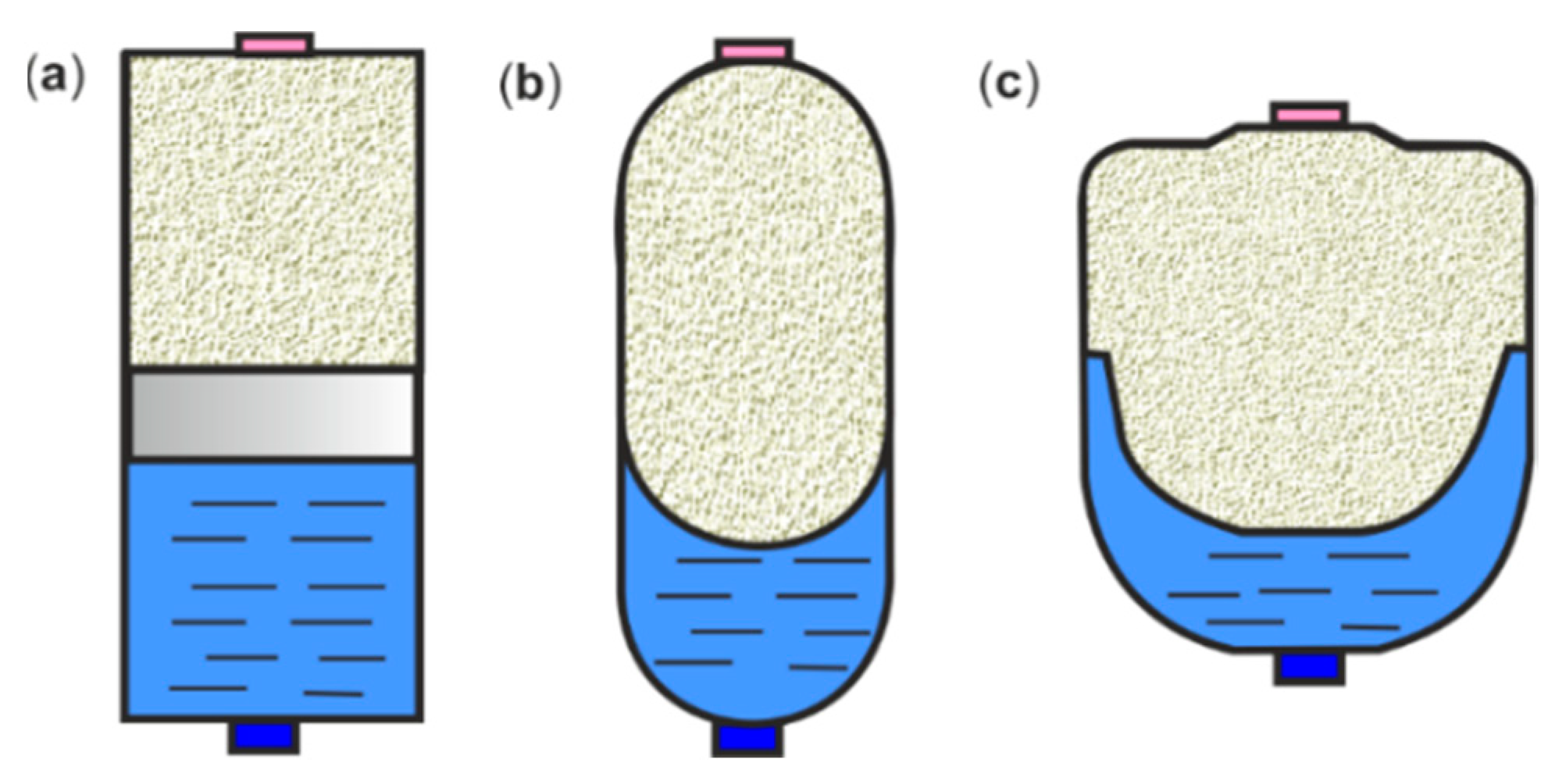
Figure 1. HPA diagrams: (a) piston, (b) bladder, and (c) diaphragm.
Energies 16 06472 g001
Figure 2. Hydraulic circuit diagram: 1—hydraulic power unit, 2—HPA, 3—directional control valve, 4—directional control valve, 5—cylinder, 6—hydraulic motor.
Energies 16 06472 g002
Figure 3. Hydraulic circuit diagram: 1—hydraulic power unit, 2—HPA, 3—directional control valve, 4—directional control valve, 5—long stroke cylinder, 6—short stroke cylinder, 7—injection moulding machine.
Energies 16 06472 g003
Figure 4. Hydraulic circuit diagram: 1—hydraulic power unit, 2—HPA, 3—directional control valve, 4—cylinder, 5—clamping device.
Energies 16 06472 g004
Figure 5. Hydraulic circuit diagram: 1—hydraulic power unit, 2—HPA, 3—on/off safety valve, 4—directional control valve, 5—cylinder, 6—feed device.
Energies 16 06472 g005
Figure 6. Hydraulic circuit diagram: (a) hydraulic brake unit: 1—hydraulic power unit, 2—HPA, 3—on-off safety valve, 4—directional control valve, 5—cylinder, 6—clutch, 7—hydraulic brake; (b) mechanical brake unit: 1—hydraulic power unit, 2—HPA, 3—on-off emergency valve, 4—directional control valve, 5—cylinder, 6—clutch, 7—mechanical brake.
Energies 16 06472 g006
Figure 7. Hydraulic circuit diagram: (a) HPA as leak compensator: 1—hydraulic power unit, 2—HPA, 3—pressure switch, 4—4/2 directional control valve, 5—cylinder; (b) HPA as thermal expansion compensator: 1—pump, 2—HPA, 3—pressure switch, 4—hydraulic motor.
Energies 16 06472 g007
Figure 8. Hydraulic circuit diagram: (a) HPA as hydraulic shock absorber: 1—hydraulic power unit, 2—HPA, 3—shut-off valve; (b) HPA as pressure pulsation damper: 1—hydraulic power unit, 2—HPA, 3—4/3 directional control valve, 4—cylinder.
Energies 16 06472 g008
Figure 9. General hydraulic propulsion with energy regeneration: (a) open-loop system; (b) closed-loop system: 1—hydraulic pump, 2—HPA, 3—hydraulic motor/pump.
Energies 16 06472 g009
Figure 10. Basic structure of HHD. (a) PHH: 1—pump/motor unit, 2—high-pressure HPA, 3—low-pressure HPA, 4—ICE, 5—mechanical gear, 6—differential; (b) 1—pump/motor unit, 2—motor/pump unit, 3—high-pressure HPA, 4—low-pressure HPA, 5—valve block, 6—ICE, 7—differential; (c) SPHH: 1—pump/motor unit, 2—motor/pump unit, 3—high-pressure HPA, 4—low-pressure HPA, 5—valve block, 6—ICE, 7, 8—mechanical gears, 9—differential.
Energies 16 06472 g010
Figure 11. Pressure–volume diagrams of the gas compression and expansion process in an HPA.
Energies 16 06472 g011
Figure 12. Volume factors versus pressure ratio for HPD (a) gas compression; (b) gas expansion.
Energies 16 06472 g012
Figure 13. Curves of the energy factors versus the pressure ratio for (a) compression; (b) expansion of the gas.
Energies 16 06472 g013
Figure 14. Curves of the HPA energy quotient versus operating pressure ratio.
Energies 16 06472 g014
Figure 15. PV diagram of the thermodynamic cycle for ideal gas processes in HPA.
Energies 16 06472 g015
Figure 16. Pressure–time curves during isochoric processes: (a) gas compression; (b) gas expansion.
Energies 16 06472 g016
Figure 17. HPA simulation model: (a) Simscape HPA block; (b) HPA calculation diagram.
Energies 16 06472 g017
Figure 18. Simscape model of the hydraulic system with an HPA block.
Energies 16 06472 g018
Figure 19. Control signals: (a) valve switching signal; (b) pressure signal.
Energies 16 06472 g019
Figure 20. Plots of the HPA parameter: (a) volume; (b) flow rate.
Energies 16 06472 g020
Figure 21. Plots of the hydraulic system parameters: (a) valve flow rate; (b) operating pressure.
Energies 16 06472 g021
Figure 22. Diagram of the dynamic model of the HPA connected to the hydraulic circuits: 1—HPA, 2—connection tube, 3—pressure source, 4—shut-off valve, 5—pressure relief valve, 6—throttle valve operated by solenoid.
Energies 16 06472 g022
Figure 23. HPA time curves: (a) volume–time curve; (b) flow rate–time curve.
Energies 16 06472 g023
Figure 24. HPA pressure–time curve.
Energies 16 06472 g024
Figure 25. Diagram of the dynamic model of a diaphragm-type HPA as pulsation damper: 1—HPA, 2—connecting tube, 3—main hydraulic pipeline.
Energies 16 06472 g025
Figure 26. Dimensionless impedance characteristics of the HPA: (a) amplitude-frequency characteristic; (b) phase-frequency characteristic.
Energies 16 06472 g026
Figure 27. Diagram of the absorption of the hydraulic shock in HTL by the HPA: 1—HPA, 2—connected tube, 3—HTL, 4—hydraulic valve.
Energies 16 06472 g027
Figure 28. Diagrams of the hydraulic shock absorption index D of the HPA: (a) for various nominal volumes V0; (b) for various filling pressures p0.
Energies 16 06472 g028
Figure 29. Diagrams of the hydraulic shock absorption index D of the HPA: (a) for various diameters dh of the connecting tube; (b) for various lengths lh of the connecting tube.
Energies 16 06472 g029
Figure 30. The elongated hot open-die forging process: (a) view of the 80 MN open-die industrial HFP; (b) view of the open-die forging process; (c) schematic diagram of the hydraulic system of the industrial open-die forging press: 1—set of supply pumps, 2—set of hydraulic accumulators, 3—control valve block, 4—hydraulic forging press, 5—multiple predictive control (MPC).
Energies 16 06472 g030
Figure 31. Control of the elongated forging process on the 80 MN industrial HFP (a) MPC controller structure; (b) open-die forging process control parameters.
Energies 16 06472 g031aEnergies 16 06472 g031b
Figure 32. View and design of the tracked mobile RBS: (a) view of a mobile RBS during a bricklaying test; (b) 3D CAD design with the components of the mobile RBS: 1—ABB six degree-of-freedom (6 DoF) industrial robot, 2—Hinowa tracked undercarriage, 3—robot support frame, 4—front hydraulic lifting–levelling module, 5—rear hydraulic lifting–levelling module, 6—hydraulic power and control module, 7—brick warehouse, 8—brick feeder, 9—touch control panel, 10—control cabinet, 11—hydraulic robot gripper.
Energies 16 06472 g032
Figure 33. Robotic bricklaying process: (a) bricklaying robot while laying bricks; (b) bricklaying robot load.
Energies 16 06472 g033
Figure 34. HLL module: (a) view of the HLL module; (b) diagram of the HLL with an HPA as a shock pulse absorber, 1—support leg, 2—hydraulic lift cylinder, 3—proportional directional control valve, 4—damping valve, 5—HPA, 6—pressure transducer.
Energies 16 06472 g034
Figure 35. Comparison of the dynamic responses of the undamped and damped shock pressure.
Energies 16 06472 g035
Table 1. The parameters of different energy storages compared.
BatteryUltracapacitorHPA
Mass 9.8 kgMass 12.2 gMass 4.53 kg
Energy capacity 1127 WhEnergy capacity 1.82 WhEnergy capacity 1.77 Wh
Voltage 48 VVoltage 2.7 VVolume capacity 950 cm3
Current 60 ACurrent 6.1 APressure 207 bar
Table 2. Comparison of the energy density of different energy storages.
Energy StorageEnergy/Volume
Wh/m3
Energy/Mass
Wh/kg
Cost/Energy
EUR/Wh
Battery195,144115.20.42
Ultracapacitor2539.702.72129
HPA12270.29376
Table 3. Comparison of the power density of different energy storages.
Energy StoragePower/Volume
kW/m3
Power/Mass
kW/kg
Cost/Power
EUR/kW
Battery325.240.192252
Ultracapacitor25882.21202
HPA75482.6970
Table 4. Economic savings of various vehicle configurations.
Vehicle
Configuration
Improvement Economic SavingsEnergy Consumption
kW/km
Energy Cost
EUR/km
ICEBase data25680.075
SHEV15.4%21740.064
SHHV33.8%17000.045
PHEV38.2%15860.046
PHHV35.9%16460.044
EV72.6%5130.020
HEHV75.7%4550.018
Disclaimer/Publisher’s Note: The statements, opinions and data contained in all publications are solely those of the individual author(s) and contributor(s) and not of MDPI and/or the editor(s). MDPI and/or the editor(s) disclaim responsibility for any injury to people or property resulting from any ideas, methods, instructions or products referred to in the content.