


From Lab to Fab: Development and Deployment of Direct Air Capture of CO2


Abstract
1. Introduction
2. DAC Technologies
2.1. Liquid Sorbent Technology
2.1.1. Aqueous Alkaline Solvents
2.1.2. Aqueous Amines
2.1.3. Ionic Liquids (IL)
2.2. Solid Sorbent Technology
2.2.1. Adsorbents
- Zeolites
- Activated Carbon (AC) and Porous Carbon
- Metal Organic Frameworks (MOFs)
2.2.2. Ion-Exchange Resin
2.2.3. Desorption/Regeneration
- Temperature swing adsorption (TSA)
- Pressure swing adsorption (PSA) or vacuum swing adsorption (VSA)
- Moisture swing adsorption (MSA)
2.3. Electrochemical Technology
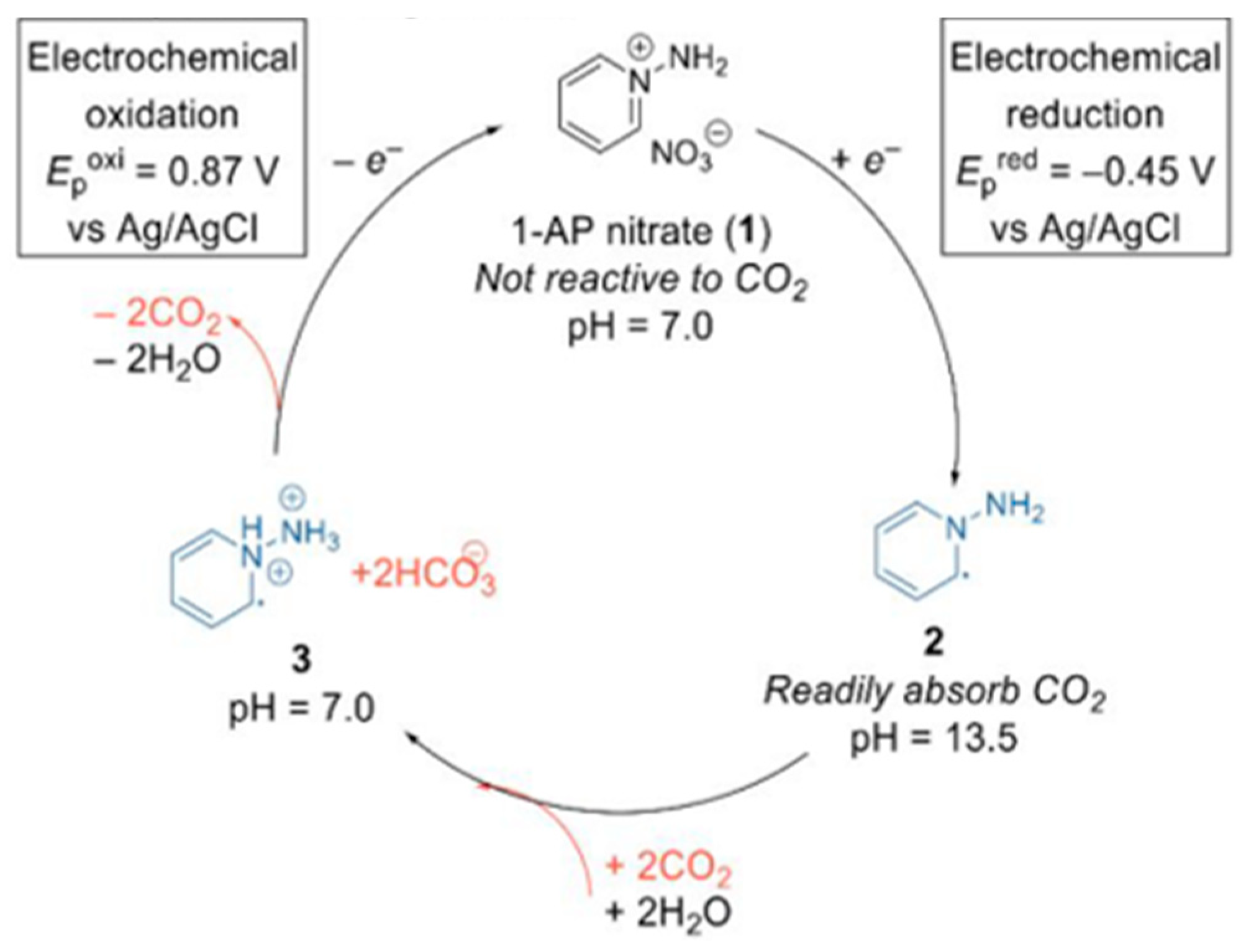
2.3.1. Electrochemical Capture
2.3.2. Electrochemical Regeneration
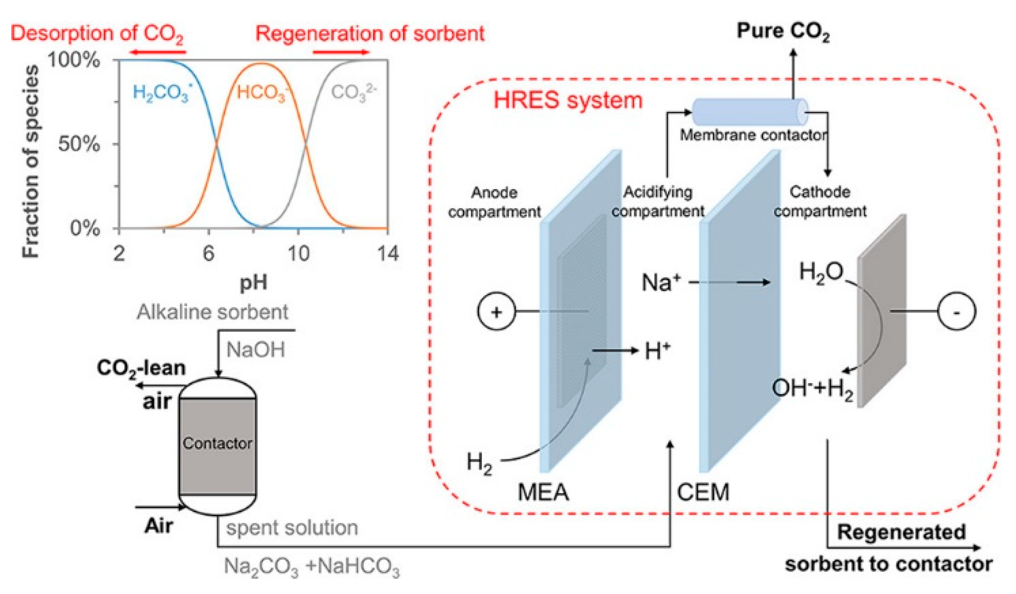
- Monopolar Membrane Electrodialysis
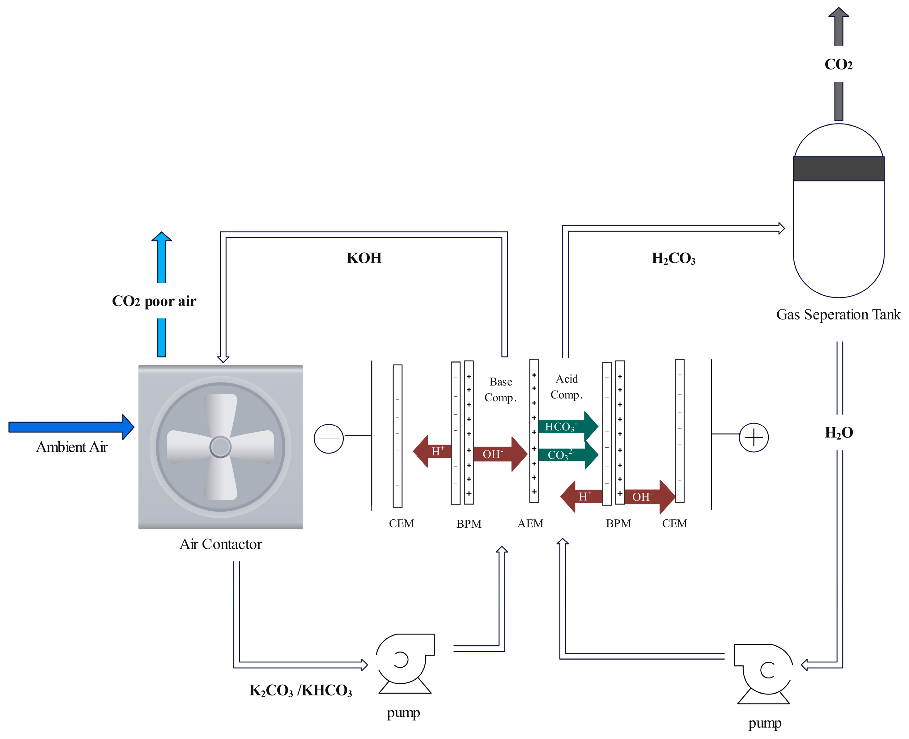
- Bipolar Membrane Electrodialysis

3. Storage and Utilization of CO2
3.1. Geological Storage
3.2. Enhanced Oil Recovery (EOR)
3.3. Fuels and Chemicals
3.4. Mineralization
3.5. Biological Utilization
4. DAC Companies
4.1. Liquid Sorbent Technology
4.1.1. Carbon Engineering
4.1.2. Carbon Blade
4.1.3. Greenlyte Carbon Technologies
4.1.4. Mission Zero Technologies
4.2. Solid Sorbent Technology
4.2.1. Climeworks
4.2.2. Global Thermostat
4.2.3. Hydrocell and Soletair Power
4.2.4. Skytree
4.2.5. Carbon Collect
4.2.6. Carbon Capture
4.2.7. Verdox
4.2.8. TerraFixing
4.2.9. Noya
4.2.10. Heirloom Carbon Technologies
4.2.11. Sustaera
4.2.12. Octavia Carbon

| Sorbent State | Company | Sorbent | Desorption Method | Capacity (CO2/year) 1 | Capture Cost (USD/tCO2) | Country of Origin | Representative Patent(s) 2 |
|---|---|---|---|---|---|---|---|
| Liquid | Carbon Engineering | KOH | Calcination | 365 t; 500 kt-1 Mt (2024) | USD 94–232 | Canada | [184,185] |
| Liquid | Carbon Blade | NaOH | EDBM | 1000 units (2025) | ~USD 100 | United States | [125] |
| Liquid | Greenlyte Carbon Technologies | PEG or polyols, and K2CO3, Na2CO3, amino acids or mixtures of these | Electrolysis | 100 tCO2 (Q4 2023); 1 ktCO2 (2026/2027) | Unknown | Germany | [186] |
| Liquid | Mission Zero Technologies | PEI (polyethyleneimine) | Electrochemical | 1000 tCO2 (2024) | Unknown | Great Britain | [129] |
| Solid | Climeworks | Amine-functionalized nanofibrillated cellulose | TVSA | 6.9 kt; 42.9 kt (2024) | USD 600–800; USD 100 (2030) | Switzerland | [187,188,189] |
| Solid | Global Thermostat | Aminopolymer | TVSA | 1 kt CO2 3; 100 kt CO2 (under FEED) | USD 300 (2025) | United States | [136,137,138,139] |
| Solid | Hydrocell/ Soletair Power | Amine-functionalized polystyrene spherical beads | TVSA | 20 t | Unknown | Finland | [145,190] |
| Solid | Skytree | Benzylamine-based ion-exchange resin beads | TSA | 10 Mt cumulative capture (2030) | Unknown | Netherlands | [191] |
| Solid | Carbon Collect | Ammonium functionalized polymer | MVTSA (TVSA and MVSA capable) | 33 t | USD 100 target | Ireland | [153,154] |
| Solid | Carbon Capture | Zeolites | TVSA | 5 Mt (2030) | United States | [163,164] | |
| Solid | Verdox | Polyanthraquinone | Electroswing adsorption | Unknown | USD 50–100 | United States | [191,192,193] |
| Solid | TerraFixing | Zeolites | TVSA | Unknown | USD 40 4 | Canada | [170] |
| Solid | Noya | May include MgO, Al2O3, K2CO3, activated carbon, monoethylamine, glycine or sarcosine. | TVSA | ~1 t | <USD 100 5 | United States | [194] |
| Solid | Heirloom | Limestone Ca(OH)2 | TSA | Unknown | USD 50 target | United States | [195] |
| Solid | Sustaera | Sodium carbonate supported on monolith | TSA | 300 ton (2023); 3000 ton (2024) | USD 175; ≤USD 100 target | United States | [196,197] |
| Solid | Octavia Carbon | Unknown | Not disclosed, likely TSA | 1000 tCO2 (2024) | USD 300–500 | Kenya | Not available |
5. DAC Energy Demand and Cost
- Capital cost, which involves the cost of equipment and the cost of land. The plant’s capacity affects these factors.
- Operating costs are the costs associated with running a business, or with running a machine, part, piece of equipment, or facility. Energy, equipment maintenance, and labor costs are critical elements in DAC plants.
- Every technology has certain unique costs attached to it. The cost of the solid sorbent and the lifetime of solid sorbent are crucial in solid sorbent technology. Since reaction efficiency is never 100%, liquid technology requires make-up inputs, such as water and sorbent [12]. In DAC plants, the air contactor’s design is also crucial. Adding several fans to increase the air velocity in the air contactor improves the plant’s performance but adds to the capital and operating cost.
6. Conclusions and Outlook
Author Contributions
Funding
Data Availability Statement
Acknowledgments
Conflicts of Interest
References
- Erans, M.; Sanz-Pérez, E.S.; Hanak, D.P.; Clulow, Z.; Reiner, D.M.; Mutch, G.A. Direct Air Capture: Process Technology, Techno-Economic and Socio-Political Challenges. Energy Environ. Sci. 2022, 15, 1360–1405. [Google Scholar] [CrossRef]
- Historical CO2 Datasets. Available online: https://www.co2.earth/historical-co2-datasets (accessed on 28 March 2023).
- Board, Ocean Studies, and National Academies of Sciences, Engineering, and Medicine. Negative Emissions Technologies and Reliable Sequestration: A Research Agenda; The National Academies Press: Washington, DC, USA, 2018. [Google Scholar] [CrossRef]
- Kumar, S.; Mondal, M.K. Equilibrium Solubility of CO2 in Aqueous Blend of 2-(Diethylamine)Ethanol and 2-(2-Aminoethylamine)Ethanol. J. Chem. Eng. Data 2018, 63, 1163–1169. [Google Scholar] [CrossRef]
- Li, K.; Van Der Poel, P.; Conway, W.; Jiang, K.; Puxty, G.; Yu, H.; Feron, P. Mechanism Investigation of Advanced Metal-Ion-Mediated Amine Regeneration: A Novel Pathway to Reducing CO2 Reaction Enthalpy in Amine-Based CO2 Capture. Environ. Sci. Technol. 2018, 52, 14538–14546. [Google Scholar] [CrossRef] [PubMed]
- Chowdhury, S.; Kumar, Y.; Shrivastava, S.; Patel, S.K.; Sangwai, J.S. A Review on the Recent Scientific and Commercial Progress on the Direct Air Capture Technology to Manage Atmospheric CO2 Concentrations and Future Perspectives. Energy Fuels 2023, 37, 10733–10757. [Google Scholar] [CrossRef]
- Motlaghzadeh, K.; Schweizer, V.; Craik, N.; Moreno-Cruz, J. Key Uncertainties behind Global Projections of Direct Air Capture Deployment. Appl. Energy 2023, 348, 121485. [Google Scholar] [CrossRef]
- Budinis, S. Direct Air Capture—Energy System—IEA. Available online: https://www.iea.org/energy-system/carbon-capture-utilisation-and-storage/direct-air-capture (accessed on 29 July 2023).
- Jiang, L.; Liu, W.; Wang, R.Q.; Gonzalez-Diaz, A.; Rojas-Michaga, M.F.; Michailos, S.; Pourkashanian, M.; Zhang, X.J.; Font-Palma, C. Sorption Direct Air Capture with CO2 Utilization. Prog. Energy Combust. Sci. 2023, 95, 101069. [Google Scholar] [CrossRef]
- Freyman, M.C.; Huang, Z.; Ravikumar, D.; Duoss, E.B.; Li, Y.; Baker, S.E.; Pang, S.H.; Schaidle, J.A. Reactive CO2 Capture: A Path Forward for Process Integration in Carbon Management. Joule 2023, 7, 631–651. [Google Scholar] [CrossRef]
- Garcia, J.A.; Villen-Guzman, M.; Rodriguez-Maroto, J.M.; Paz-Garcia, J.M. Technical Analysis of CO2 capture Pathways and Technologies. J. Environ. Chem. Eng. 2022, 10, 108470. [Google Scholar] [CrossRef]
- Keith, D.W.; Holmes, G.; St. Angelo, D.; Heidel, K. A Process for Capturing CO2 from the Atmosphere. Joule 2018, 2, 1573–1594. [Google Scholar] [CrossRef]
- Marinič, D.; Likozar, B. Direct Air Capture Multiscale Modelling: From Capture Material Optimization to Process Simulations. J. Clean. Prod. 2023, 408, 137185. [Google Scholar] [CrossRef]
- Ozkan, M.; Nayak, S.P.; Ruiz, A.D.; Jiang, W. Current Status and Pillars of Direct Air Capture Technologies. iScience 2022, 25, 103990. [Google Scholar] [CrossRef] [PubMed]
- Sanz-Pérez, E.S.; Murdock, C.R.; Didas, S.A.; Jones, C.W. Direct Capture of CO2 from Ambient Air. Chem. Rev. 2016, 116, 11840–11876. [Google Scholar] [CrossRef] [PubMed]
- Fasihi, M.; Efimova, O.; Breyer, C. Techno-Economic Assessment of CO2 Direct Air Capture Plants. J. Clean. Prod. 2019, 224, 957–980. [Google Scholar] [CrossRef]
- Custelcean, R. Direct Air Capture of CO2 Using Solvents. Annu. Rev. Chem. Biomol. Eng. 2022, 13, 217–234. [Google Scholar] [CrossRef] [PubMed]
- Eisaman, M.D.; Schwartz, D.E.; Amic, S.; Larner, D.; Zesch, J.; Torres, F.; Littau, K. Energy-Efficient Electrochemical CO2 Capture from the Atmosphere. Technical Proceedings of the 2009 Clean Technology Conference and Trade Show. TechConnect Briefs 2009, 175–178. [Google Scholar]
- Castel, C.; Bounaceur, R.; Favre, E. Membrane Processes for Direct Carbon Dioxide Capture From Air: Possibilities and Limitations. Front. Chem. Eng. 2021, 3, 668867. [Google Scholar] [CrossRef]
- Goldberg, D.S.; Lackner, K.S.; Han, P.; Slagle, A.L.; Wang, T. Co-Location of Air Capture, Subseafloor CO2 Sequestration, and Energy Production on the Kerguelen Plateau. Environ. Sci. Technol. 2013, 47, 7521–7529. [Google Scholar] [CrossRef] [PubMed]
- Sifat, N.S.; Haseli, Y. A Critical Review of CO2 Capture Technologies and Prospects for Clean Power Generation. Energies 2019, 12, 4143. [Google Scholar] [CrossRef]
- Quang, D.V.; Milani, D.; Abu Zahra, M. A Review of Potential Routes to Zero and Negative Emission Technologies via the Integration of Renewable Energies with CO2 Capture Processes. Int. J. Greenh. Gas Control 2023, 124, 103862. [Google Scholar] [CrossRef]
- Lackner, K.; Ziock, H.; Grimes, P. Carbon Dioxide Extraction from Air: Is It an Option? Los Alamos National Lab. (LANL): Los Alamos, NM, USA, 1999.
- Baciocchi, R.; Storti, G.; Mazzotti, M. Process Design and Energy Requirements for the Capture of Carbon Dioxide from Air. Chem. Eng. Process. Process Intensif. 2006, 12, 1047–1058. [Google Scholar] [CrossRef]
- Sodiq, A.; Abdullatif, Y.; Aissa, B.; Ostovar, A.; Nassar, N.; El-Naas, M.; Amhamed, A. A Review on Progress Made in Direct Air Capture of CO2. Environ. Technol. Innov. 2023, 29, 102991. [Google Scholar] [CrossRef]
- Keith, D.W.; Ha-Duong, M.; Stolaroff, J.K. Climate Strategy with CO2 Capture from the Air. Clim. Change 2006, 74, 17–45. [Google Scholar] [CrossRef]
- Carbon Engineering|Direct Air Capture of CO2|Home. Available online: https://carbonengineering.com/ (accessed on 2 February 2023).
- Zeman, F. Experimental Results for Capturing CO2 from the Atmosphere. AIChE J. 2008, 54, 1396–1399. [Google Scholar] [CrossRef]
- Shi, X.; Xiao, H.; Azarabadi, H.; Song, J.; Wu, X.; Chen, X.; Lackner, K.S. Sorbents for the Direct Capture of CO2 from Ambient Air. Angew. Chem.-Int. Ed. 2020, 59, 6984–7006. [Google Scholar] [CrossRef] [PubMed]
- El Hadri, N.; Quang, D.V.; Goetheer, E.L.V.; Abu Zahra, M.R.M. Aqueous Amine Solution Characterization for Post-Combustion CO2 Capture Process. Appl. Energy 2017, 185, 1433–1449. [Google Scholar] [CrossRef]
- Shi, X.; Xiao, H.; Liao, X.; Armstrong, M.; Chen, X.; Lackner, K.S. Humidity Effect on Ion Behaviors of Moisture-Driven CO2 Sorbents. J. Chem. Phys. 2018, 149, 164708. [Google Scholar] [CrossRef]
- Miao, Y.; Wang, Y.; Zhu, X.; Chen, W.; He, Z.; Yu, L.; Li, J. Minimizing the Effect of Oxygen on Supported Polyamine for Direct Air Capture. Sep. Purif. Technol. 2022, 298, 121583. [Google Scholar] [CrossRef]
- Barzagli, F.; Giorgi, C.; Mani, F.; Peruzzini, M. Screening Study of Different Amine-Based Solutions as Sorbents for Direct CO2 Capture from Air. ACS Sustain. Chem. Eng. 2020, 8, 14013–14021. [Google Scholar] [CrossRef]
- Kiani, A.; Jiang, K.; Feron, P. Techno-Economic Assessment for CO2 Capture From Air Using a Conventional Liquid-Based Absorption Process. Front. Energy Res. 2020, 8, 92. [Google Scholar] [CrossRef]
- Brennecke, J.F.; Maginn, E.J. Ionic Liquids: Innovative Fluids for Chemical Processing. AIChE J. 2001, 47, 2384–2389. [Google Scholar] [CrossRef]
- Wang, T.; Jens, K.J. Possible Pathways for Oxidative Degradation of β-Hydroxyl Alkanolamine for Post-Combustion CO2 Capture. Energy Procedia 2014, 51, 259–266. [Google Scholar] [CrossRef]
- Hospital-Benito, D.; Moya, C.; Gazzani, M.; Palomar, J. Direct Air Capture Based on Ionic Liquids: From Molecular Design to Process Assessment. Chem. Eng. J. 2023, 468, 143630. [Google Scholar] [CrossRef]
- Zeng, S.; Zhang, X.; Bai, L.; Zhang, X.; Wang, H.; Wang, J.; Bao, D.; Li, M.; Liu, X.; Zhang, S. Ionic-Liquid-Based CO2 Capture Systems: Structure, Interaction and Process. Chem. Rev. 2017, 117, 9625–9673. [Google Scholar] [CrossRef] [PubMed]
- Aghaie, M.; Rezaei, N.; Zendehboudi, S. A Systematic Review on CO2 Capture with Ionic Liquids: Current Status and Future Prospects. Renew. Sustain. Energy Rev. 2018, 96, 502–525. [Google Scholar] [CrossRef]
- Ramdin, M.; De Loos, T.W.; Vlugt, T.J.H. State-of-the-Art of CO2 Capture with Ionic Liquids. Ind. Eng. Chem. Res. 2012, 51, 8149–8177. [Google Scholar] [CrossRef]
- Hayes, R.; Warr, G.G.; Atkin, R. Structure and Nanostructure in Ionic Liquids. Chem. Rev. 2015, 115, 6357–6426. [Google Scholar] [CrossRef] [PubMed]
- Krupiczka, R.; Rotkegel, A.; Ziobrowski, Z. Comparative Study of CO2 Absorption in Packed Column Using Imidazolium Based Ionic Liquids and MEA Solution. Sep. Purif. Technol. 2015, 149, 228–236. [Google Scholar] [CrossRef]
- Moitra, D.; Mokhtari-Nori, N.; Siniard, K.M.; Qiu, L.; Fan, J.; Dong, Z.; Hu, W.; Liu, H.; Jiang, D.; Lin, H.; et al. High-Performance CO2 Capture from Air by Harnessing the Power of CaO- and Superbase-Ionic-Liquid-Engineered Sorbents. ChemSusChem 2023, e202300808. [Google Scholar] [CrossRef]
- Peng, H.; Zhang, Q.; Wang, Y.; Gao, H.; Zhang, N.; Zhou, J.; Zhang, L.; Yang, Q.; Yang, Q.; Lu, Z. Atomically Dispersed Lewis Acid Sites Meet Poly(Ionic Liquid)s Networks for Solvent-Free and Co-Catalyst-Free Conversion of CO2 to Cyclic Carbonates. Appl. Catal. B 2022, 313, 121463. [Google Scholar] [CrossRef]
- Ding, M.; Jiang, H.L. Incorporation of Imidazolium-Based Poly(Ionic Liquid)s into a Metal-Organic Framework for CO2 Capture and Conversion. ACS Catal. 2018, 8, 3194–3201. [Google Scholar] [CrossRef]
- Qiu, L.; Peng, L.; Moitra, D.; Liu, H.; Fu, Y.; Dong, Z.; Hu, W.; Lei, M.; Jiang, D.; Lin, H.; et al. Harnessing the Hybridization of a Metal-Organic Framework and Superbase-Derived Ionic Liquid for High-Performance Direct Air Capture of CO2. Small 2023, 2302708. [Google Scholar] [CrossRef] [PubMed]
- Valentine, J.; Zoelle, A.; Homsy, S.; Mantripragada, H.; Woods, M.; Roy, N.; Kilstofte, A.; Sturdivan, M.; Steutermann, M.; Fout, T. Direct Air Capture Case Studies: Sorbent System; National Energy Technology Laboratory (NETL): Pittsburgh, PA, USA, 2022. [CrossRef]
- McQueen, N.; Gomes, K.V.; McCormick, C.; Blumanthal, K.; Pisciotta, M.; Wilcox, J. A Review of Direct Air Capture (DAC): Scaling up Commercial Technologies and Innovating for the Future. Prog. Energy 2021, 3, 032001. [Google Scholar] [CrossRef]
- Barkakaty, B.; Sumpter, B.G.; Ivanov, I.N.; Potter, M.E.; Jones, C.W.; Lokitz, B.S. Emerging Materials for Lowering Atmospheric Carbon. Environ. Technol. Innov. 2017, 7, 30–43. [Google Scholar] [CrossRef]
- Zagho, M.M.; Hassan, M.K.; Khraisheh, M.; Al-Maadeed, M.A.A.; Nazarenko, S. A Review on Recent Advances in CO2 Separation Using Zeolite and Zeolite-like Materials as Adsorbents and Fillers in Mixed Matrix Membranes (MMMs). Chem. Eng. J. Adv. 2021, 6, 100091. [Google Scholar] [CrossRef]
- Thakkar, H.; Issa, A.; Rownaghi, A.A.; Rezaei, F. CO2 Capture from Air Using Amine-Functionalized Kaolin-Based Zeolites. Chem. Eng. Technol. 2017, 40, 1999–2007. [Google Scholar] [CrossRef]
- Wilson, S.M.W.; Tezel, F.H. Direct Dry Air Capture of CO2 Using VTSA with Faujasite Zeolites. Ind. Eng. Chem. Res. 2020, 59, 8783–8794. [Google Scholar] [CrossRef]
- Kamran, U.; Park, S.J. Chemically Modified Carbonaceous Adsorbents for Enhanced CO2 Capture: A Review. J. Clean. Prod. 2021, 290, 125776. [Google Scholar] [CrossRef]
- Kua, H.W.; Pedapati, C.; Lee, R.V.; Kawi, S. Effect of Indoor Contamination on Carbon Dioxide Adsorption of Wood-Based Biochar—Lessons for Direct Air Capture. J. Clean. Prod. 2019, 210, 860–871. [Google Scholar] [CrossRef]
- Kishibayev, K.K.; Serafin, J.; Tokpayev, R.R.; Khavaza, T.N.; Atchabarova, A.A.; Abduakhytova, D.A.; Ibraimov, Z.T.; Sreńscek-Nazzal, J. Physical and Chemical Properties of Activated Carbon Synthesized from Plant Wastes and Shungite for CO2 Capture. J. Environ. Chem. Eng. 2021, 9, 106798. [Google Scholar] [CrossRef]
- Sun, N.; Tang, Z.; Wei, W.; Snape, C.E.; Sun, Y. Solid Adsorbents for Low-Temperature CO2 Capture with Low-Energy Penalties Leading to More Effective Integrated Solutions for Power Generation and Industrial Processes. Front. Energy Res. 2015, 3, 123870. [Google Scholar] [CrossRef]
- Kamran, U.; Choi, J.R.; Park, S.J. A Role of Activators for Efficient CO2 Affinity on Polyacrylonitrile-Based Porous Carbon Materials. Front. Chem. 2020, 8, 558899. [Google Scholar] [CrossRef] [PubMed]
- Li, J.R.; Ma, Y.; McCarthy, M.C.; Sculley, J.; Yu, J.; Jeong, H.K.; Balbuena, P.B.; Zhou, H.C. Carbon Dioxide Capture-Related Gas Adsorption and Separation in Metal-Organic Frameworks. Coord. Chem. Rev. 2011, 255, 1791–1823. [Google Scholar] [CrossRef]
- Jeong, C.; Ansari, M.Z.; Hakeem Anwer, A.; Kim, S.H.; Nasar, A.; Shoeb, M.; Mashkoor, F. A Review on Metal-Organic Frameworks for the Removal of Hazardous Environmental Contaminants. Sep. Purif. Technol. 2023, 305, 122416. [Google Scholar] [CrossRef]
- Ding, M.; Flaig, R.W.; Jiang, H.L.; Yaghi, O.M. Carbon Capture and Conversion Using Metal–Organic Frameworks and MOF-Based Materials. Chem. Soc. Rev. 2019, 48, 2783–2828. [Google Scholar] [CrossRef] [PubMed]
- Liu, F.; Wang, T.; Dong, H.; Liu, W. Modified Metal–Organic Framework by a Novel Coordinatively Unsaturated Amine Grafting Mechanism for Direct Air Capture of CO2. Chem. Eng. J. 2023, 454, 140431. [Google Scholar] [CrossRef]
- Alexandratos, S.D. Ion-Exchange Resins: A Retrospective from Industrial and Engineering Chemistry Research. Ind. Eng. Chem. Res. 2009, 48, 388–398. [Google Scholar] [CrossRef]
- Lackner, K.S. Capture of Carbon Dioxide from Ambient Air. Eur. Phys. J. Spec. Top. 2009, 176, 93–106. [Google Scholar] [CrossRef]
- Chen, H.; Dong, H.; Shi, Z.; SenGupta, A.K. Direct Air Capture (DAC) and Sequestration of CO2: Dramatic Effect of Coordinated Cu(II) onto a Chela Weak Base Ion Exchanger. Sci. Adv. 2023, 9, eadg1956. [Google Scholar] [CrossRef]
- Wang, T.; Liu, J.; Huang, H.; Fang, M.; Luo, Z. Preparation and Kinetics of a Heterogeneous Sorbent for CO2 Capture from the Atmosphere. Chem. Eng. J. 2016, 284, 679–686. [Google Scholar] [CrossRef]
- Wang, X.; Song, J.; Chen, Y.; Xiao, H.; Shi, X.; Liu, Y.; Zhu, L.; He, Y.L.; Chen, X. CO2 Absorption over Ion Exchange Resins: The Effect of Amine Functional Groups and Microporous Structures. Ind. Eng. Chem. Res. 2020, 59, 16507–16515. [Google Scholar] [CrossRef]
- Drechsler, C.; Agar, D.W. Simulation and Optimization of a Novel Moving Belt Adsorber Concept for the Direct Air Capture of Carbon Dioxide. Comput. Chem. Eng. 2019, 126, 520–534. [Google Scholar] [CrossRef]
- Jahandar Lashaki, M.; Khiavi, S.; Sayari, A. Stability of Amine-Functionalized CO2 Adsorbents: A Multifaceted Puzzle. Chem. Soc. Rev. 2019, 48, 3320–3405. [Google Scholar] [CrossRef] [PubMed]
- Subraveti, S.G.; Pai, K.N.; Rajagopalan, A.K.; Wilkins, N.S.; Rajendran, A.; Jayaraman, A.; Alptekin, G. Cycle Design and Optimization of Pressure Swing Adsorption Cycles for Pre-Combustion CO2 Capture. Appl. Energy 2019, 254, 113624. [Google Scholar] [CrossRef]
- Siqueira, R.M.; Freitas, G.R.; Peixoto, H.R.; Nascimento, J.F.D.; Musse, A.P.S.; Torres, A.E.B.; Azevedo, D.C.S.; Bastos-Neto, M. Carbon Dioxide Capture by Pressure Swing Adsorption. Energy Procedia 2017, 114, 2182–2192. [Google Scholar] [CrossRef]
- Sreenivasulu, B.; Gayatri, D.V.; Sreedhar, I.; Raghavan, K.V. A Journey into the Process and Engineering Aspects of Carbon Capture Technologies. Renew. Sustain. Energy Rev. 2015, 41, 1324–1350. [Google Scholar] [CrossRef]
- Zhao, R.; Zhao, L.; Deng, S.; Song, C.; He, J.; Shao, Y.; Li, S. A Comparative Study on CO2 Capture Performance of Vacuum-Pressure Swing Adsorption and Pressure-Temperature Swing Adsorption Based on Carbon Pump Cycle. Energy 2017, 137, 495–509. [Google Scholar] [CrossRef]
- Beuttler, C.; Charles, L.; Wurzbacher, J. The Role of Direct Air Capture in Mitigation of Anthropogenic Greenhouse Gas Emissions. Front. Clim. 2019, 1, 10. [Google Scholar] [CrossRef]
- Wang, T.; Liu, J.; Fang, M.; Luo, Z. A Moisture Swing Sorbent for Direct Air Capture of Carbon Dioxide: Thermodynamic and Kinetic Analysis. Energy Procedia 2013, 37, 6096–6104. [Google Scholar] [CrossRef]
- Wang, T.; Lackner, K.S.; Wright, A. Moisture Swing Sorbent for Carbon Dioxide Capture from Ambient Air. Environ. Sci. Technol. 2011, 45, 6670–6675. [Google Scholar] [CrossRef]
- Lackner, K.S.; Brennan, S.; Matter, J.M.; Park, A.H.A.; Wright, A.; Van Der Zwaan, B. The Urgency of the Development of CO2 Capture from Ambient Air. Proc. Natl. Acad. Sci. USA 2012, 109, 13156–13162. [Google Scholar] [CrossRef]
- Muroyama, A.P.; Pătru, A.; Gubler, L. Review—CO2 Separation and Transport via Electrochemical Methods. J. Electrochem. Soc. 2020, 167, 133504. [Google Scholar] [CrossRef]
- Shu, Q.; Legrand, L.; Kuntke, P.; Tedesco, M.; Hamelers, H.V.M. Electrochemical Regeneration of Spent Alkaline Absorbent from Direct Air Capture. Environ. Sci. Technol. 2020, 54, 8990–8998. [Google Scholar] [CrossRef] [PubMed]
- Wynveen, R.A.; Schubert, F.H.; Powell, J.D. One-Man, Self-Contained CO2 Concentrating System; NASA: Washington, DC, USA, 1972.
- Muroyama, A.P.; Beard, A.; Pribyl-Kranewitter, B.; Gubler, L. Separation of CO2 from Dilute Gas Streams Using a Membrane Electrochemical Cell. ACS EST Eng. 2021, 1, 905–916. [Google Scholar] [CrossRef]
- Renfrew, S.E.; Starr, D.E.; Strasser, P. Electrochemical Approaches toward CO2 Capture and Concentration. ACS Catal. 2020, 10, 13058–13074. [Google Scholar] [CrossRef]
- Voskian, S.; Hatton, T.A. Faradaic Electro-Swing Reactive Adsorption for CO2 Capture. Energy Environ. Sci. 2019, 12, 3530–3547. [Google Scholar] [CrossRef]
- Seo, H.; Rahimi, M.; Hatton, T.A. Electrochemical Carbon Dioxide Capture and Release with a Redox-Active Amine. J. Am. Chem. Soc. 2022, 144, 2164–2170. [Google Scholar] [CrossRef]
- Seo, H.; Hatton, T.A. Electrochemical Direct Air Capture of CO2 Using Neutral Red as Reversible Redox-Active Material. Nat. Commun. 2023, 14, 313. [Google Scholar] [CrossRef]
- Kemp, K.W.; Ostericher, A.L.; Olmstead, D.E. Systems and Methods for Capturing Carbon Dioxide and Regenerating a Capture Solution. U.S. Patent 17/735,943, 17 November 2022. [Google Scholar]
- Sharifian, R.; Boer, L.; Wagterveld, R.M.; Vermaas, D.A. Oceanic Carbon Capture through Electrochemically Induced in Situ Carbonate Mineralization Using Bipolar Membrane. Chem. Eng. J. 2022, 438, 135326. [Google Scholar] [CrossRef]
- Pärnamäe, R.; Mareev, S.; Nikonenko, V.; Melnikov, S.; Sheldeshov, N.; Zabolotskii, V.; Hamelers, H.V.M.; Tedesco, M. Bipolar Membranes: A Review on Principles, Latest Developments, and Applications. J. Memb. Sci. 2021, 617, 118538. [Google Scholar] [CrossRef]
- Sabatino, F.; Mehta, M.; Grimm, A.; Gazzani, M.; Gallucci, F.; Kramer, G.J.; Van, M.; Annaland, S. Evaluation of a Direct Air Capture Process Combining Wet Scrubbing and Bipolar Membrane Electrodialysis. ACS Publ. 2020, 59, 7007–7020. [Google Scholar] [CrossRef]
- Huang, C.; Xu, T. Electrodialysis with Bipolar Membranes for Sustainable Development. Environ. Sci. Technol. 2006, 40, 5233–5243. [Google Scholar] [CrossRef] [PubMed]
- IPCC. Global Warming of 1.5 °C: IPCC Special Report on Impacts of Global Warming of 1.5 °C above Pre-Industrial Levels in Context of Strengthening Response to Climate Change, Sustainable Development, and Efforts to Eradicate Poverty; IPCC: Geneva, Switzerland, 2022. [Google Scholar] [CrossRef]
- Pant, D.; Shah, K.K.; Sharma, S.; Bhatta, M.; Tripathi, S.; Pandey, H.P.; Tiwari, H.; Shrestha, J.; Bhat, A.K. Soil and Ocean Carbon Sequestration, Carbon Capture, Utilization, and Storage as Negative Emission Strategies for Global Climate Change. J. Soil. Sci. Plant Nutr. 2023, 23, 1421–1437. [Google Scholar] [CrossRef]
- Hitchon, B. Aquifer Disposal of Carbon Dioxide: Hydrodynamic and Mineral Trapping—Proof of Concept; Alberta Research Council: Devon, AB, Canada, 1996. [Google Scholar]
- Insights Series 2015—Storing CO2 through Enhanced Oil Recovery—Analysis—IEA. Available online: https://www.iea.org/reports/storing-co2-through-enhanced-oil-recovery (accessed on 16 July 2023).
- Wang, X.; Yuan, Y.; Du, Y.; Golsanami, N.; Malozyomov, B.V.; Martyushev, N.V.; Kukartsev, V.V.; Tynchenko, V.S.; Bukhtoyarov, V.V.; Wu, X.; et al. Overview of Methods for Enhanced Oil Recovery from Conventional and Unconventional Reservoirs. Energies 2023, 16, 4907. [Google Scholar] [CrossRef]
- Technology Roadmap Carbon Capture and Storage in Industrial Applications; Global CCS Institute: Melbourne, Australia, 2011.
- Net Zero by 2050—Analysis—IEA. Available online: https://www.iea.org/reports/net-zero-by-2050 (accessed on 5 February 2023).
- Ghiat, I.; Al-Ansari, T. A Review of Carbon Capture and Utilisation as a CO2 Abatement Opportunity within the EWF Nexus. J. CO2 Util. 2021, 45, 101432. [Google Scholar] [CrossRef]
- Li, Z.; Das, S.; Hongmanorom, P.; Dewangan, N.; Wai, M.H.; Kawi, S. Silica-Based Micro- and Mesoporous Catalysts for Dry Reforming of Methane. Catal. Sci. Technol. 2018, 8, 2763–2778. [Google Scholar] [CrossRef]
- Jang, W.J.; Shim, J.O.; Kim, H.M.; Yoo, S.Y.; Roh, H.S. A Review on Dry Reforming of Methane in Aspect of Catalytic Properties. Catal. Today 2019, 324, 15–26. [Google Scholar] [CrossRef]
- Mustafa, A.; Lougou, B.G.; Shuai, Y.; Wang, Z.; Tan, H. Current Technology Development for CO2 Utilization into Solar Fuels and Chemicals: A Review. J. Energy Chem. 2020, 49, 96–123. [Google Scholar] [CrossRef]
- Ranjbar, A.; Irankhah, A.; Aghamiri, S.F. Reverse Water Gas Shift Reaction and CO2 Mitigation: Nanocrystalline MgO as a Support for Nickel Based Catalysts. J. Environ. Chem. Eng. 2018, 6, 4945–4952. [Google Scholar] [CrossRef]
- Kattel, S.; Liu, P.; Chen, J.G. Tuning Selectivity of CO2 Hydrogenation Reactions at the Metal/Oxide Interface. J. Am. Chem. Soc. 2017, 139, 9739–9754. [Google Scholar] [CrossRef]
- Porosoff, M.D.; Yan, B.; Chen, J.G. Catalytic Reduction of CO2 by H2 for Synthesis of CO, Methanol and Hydrocarbons: Challenges and Opportunities. Energy Environ. Sci. 2016, 9, 62–73. [Google Scholar] [CrossRef]
- Onishi, N.; Laurenczy, G.; Beller, M.; Himeda, Y. Recent Progress for Reversible Homogeneous Catalytic Hydrogen Storage in Formic Acid and in Methanol. Coord. Chem. Rev. 2018, 373, 317–332. [Google Scholar] [CrossRef]
- Dang, S.; Yang, H.; Gao, P.; Wang, H.; Li, X.; Wei, W.; Sun, Y. A Review of Research Progress on Heterogeneous Catalysts for Methanol Synthesis from Carbon Dioxide Hydrogenation. Catal. Today 2019, 330, 61–75. [Google Scholar] [CrossRef]
- Li, W.; Wang, H.; Jiang, X.; Zhu, J.; Liu, Z.; Guo, X.; Song, C. A Short Review of Recent Advances in CO2 Hydrogenation to Hydrocarbons over Heterogeneous Catalysts. RSC Adv. 2018, 8, 7651–7669. [Google Scholar] [CrossRef] [PubMed]
- Patricio, J.; Angelis-Dimakis, A.; Castillo-Castillo, A.; Kalmykova, Y.; Rosado, L. Method to Identify Opportunities for CCU at Regional Level—Matching Sources and Receivers. J. CO2 Util. 2017, 22, 330–345. [Google Scholar] [CrossRef]
- Veselovskaya, J.V.; Parunin, P.D.; Netskina, O.V.; Okunev, A.G. A Novel Process for Renewable Methane Production: Combining Direct Air Capture by K2CO3/Alumina Sorbent with CO2 Methanation over Ru/Alumina Catalyst. Top. Catal. 2018, 61, 1528–1536. [Google Scholar] [CrossRef]
- Kiani, A.; Lejeune, M.; Li, C.; Patel, J.; Feron, P. Liquefied Synthetic Methane from Ambient CO2 and Renewable H2—A Technoeconomic Study. J. Nat. Gas. Sci. Eng. 2021, 94, 104079. [Google Scholar] [CrossRef]
- Gür, T.M. Carbon Dioxide Emissions, Capture, Storage and Utilization: Review of Materials, Processes and Technologies. Prog. Energy Combust. Sci. 2022, 89, 100965. [Google Scholar] [CrossRef]
- Zhang, Z.; Pan, S.Y.; Li, H.; Cai, J.; Olabi, A.G.; Anthony, E.J.; Manovic, V. Recent Advances in Carbon Dioxide Utilization. Renew. Sustain. Energy Rev. 2020, 125, 109799. [Google Scholar] [CrossRef]
- Doucet: Scoping Study on CO2 Mineralization Technologies—Google Scholar. Available online: https://scholar.google.com/scholar?cluster=12645457356333919173&hl=en&oi=scholarr (accessed on 27 July 2023).
- Kelemen, P.B.; McQueen, N.; Wilcox, J.; Renforth, P.; Dipple, G.; Vankeuren, A.P. Engineered Carbon Mineralization in Ultramafic Rocks for CO2 Removal from Air: Review and New Insights. Chem. Geol. 2020, 550, 119628. [Google Scholar] [CrossRef]
- Hanifa, M.; Agarwal, R.; Sharma, U.; Thapliyal, P.C.; Singh, L.P. A Review on CO2 Capture and Sequestration in the Construction Industry: Emerging Approaches and Commercialised Technologies. J. CO2 Util. 2023, 67, 102292. [Google Scholar] [CrossRef]
- Cheah, W.Y.; Ling, T.C.; Juan, J.C.; Lee, D.J.; Chang, J.S.; Show, P.L. Biorefineries of Carbon Dioxide: From Carbon Capture and Storage (CCS) to Bioenergies Production. Bioresour. Technol. 2016, 215, 346–356. [Google Scholar] [CrossRef] [PubMed]
- Cheah, W.Y.; Show, P.L.; Chang, J.S.; Ling, T.C.; Juan, J.C. Biosequestration of Atmospheric CO2 and Flue Gas-Containing CO2 by Microalgae. Bioresour. Technol. 2015, 184, 190–201. [Google Scholar] [CrossRef] [PubMed]
- Negoro, M.; Shioji, N.; Miyamoto, K.; Micira, Y. Growth of Microalgae in High CO2 Gas and Effects of SOX and NOX. Appl. Biochem. Biotechnol. 1991, 28–29, 877–886. [Google Scholar] [CrossRef] [PubMed]
- Zhou, W.; Wang, J.; Chen, P.; Ji, C.; Kang, Q.; Lu, B.; Li, K.; Liu, J.; Ruan, R. Bio-Mitigation of Carbon Dioxide Using Microalgal Systems: Advances and Perspectives. Renew. Sustain. Energy Rev. 2017, 76, 1163–1175. [Google Scholar] [CrossRef]
- Wilcox, J.; Psarras, P.C.; Liguori, S. Assessment of Reasonable Opportunities for Direct Air Capture. Environ. Res. Lett. 2017, 12, 065001. [Google Scholar] [CrossRef]
- Yu, J. Bio-Based Products from Solar Energy and Carbon Dioxide. Trends Biotechnol. 2014, 32, 5–10. [Google Scholar] [CrossRef] [PubMed]
- Pikaar, I.; de Vrieze, J.; Rabaey, K.; Herrero, M.; Smith, P.; Verstraete, W. Carbon Emission Avoidance and Capture by Producing In-Reactor Microbial Biomass Based Food, Feed and Slow Release Fertilizer: Potentials and Limitations. Sci. Total Environ. 2018, 644, 1525–1530. [Google Scholar] [CrossRef]
- Leonzio, G.; Fennell, P.; Shah, N. Analysis of Technologies for Carbon Dioxide Capture from the Air. Appl. Sci. 2022, 12, 8321. [Google Scholar] [CrossRef]
- RoCo. Available online: https://roco.global/ (accessed on 26 July 2023).
- Direct Air Capture|Carbon Blade, Distributed Direct Air Capture Solution. Available online: https://www.carbon-blade.com/ (accessed on 9 July 2023).
- Nulwala, H. Direct Air Capture of CO2 Using Leaf-like Layered Contactor Coupled with Electro Dialysis Bipolar Membrane Regeneration. 2022. Available online: https://patentimages.storage.googleapis.com/53/78/26/384c32c879f713/WO2022192501A1.pdf (accessed on 22 May 2023).
- Fueling the Circular Carbon Economy|CHEManager. Available online: https://www.chemanager-online.com/en/news/fueling-circular-carbon-economy (accessed on 25 May 2023).
- Greenlyte Carbon Technologies. Available online: https://www.greenlyte.tech/ (accessed on 25 May 2023).
- Projects Selected for Phase 2 of the Direct Air Capture and Greenhouse Gas Removal Programme—GOV.UK. Available online: https://www.gov.uk/government/publications/direct-air-capture-and-other-greenhouse-gas-removal-technologies-competition/projects-selected-for-phase-2-of-the-direct-air-capture-and-greenhouse-gas-removal-programme (accessed on 1 June 2023).
- Gobaille-Shaw, G.; Ghosh, S.; Chadwick, N. Method of Capturing a Target Species from a Gas. 2022. Available online: https://patentimages.storage.googleapis.com/bb/2e/8a/ff248227651116/WO2022195299A1.pdf (accessed on 31 May 2023).
- Not Boring Founders: Nicholas Chadwick, Mission Zeries Technologies—YouTube. Available online: https://www.youtube.com/watch?v=Ny0bJ0Ex99U (accessed on 26 July 2023).
- Our Technology—Mission Zero Technologies—Home & News. Available online: https://www.missionzero.tech/our-technology (accessed on 1 June 2023).
- Achieve Net Zero Targets with Climeworks Direct Air Capture. Available online: https://climeworks.com/ (accessed on 5 February 2023).
- Direct Action: Carbon Capture Gears up for Climate Battle. Available online: https://www.theengineer.co.uk/content/in-depth/direct-action-carbon-capture-gears-up-for-climate-battle (accessed on 9 July 2023).
- Racing against the Clock to Decarbonise the Planet—FT Channels. Available online: https://channels.ft.com/en/rethink/racing-against-the-clock-to-decarbonise-the-planet/ (accessed on 11 July 2023).
- Climeworks Confirms Expansion of U.S. Team in Coming Year to Meet Increasing Carbon Removal Industry Demand. Available online: https://climeworks.com/news/expanding-our-us-team (accessed on 21 August 2023).
- Khunsupat, R.; Jones, C.W.; Bali, S. Supported Poly(Allyl)Amine and Derivatives for CO2 Capture from Flue Gas or Ultra-Dilute Gas Streams Such as Ambient Air or Admixtures Thereof. U.S. Patent 20220040669A1, 10 February 2022. [Google Scholar]
- Eisenberger, P.; Ping, E.W.; Sakwa-Novak, M. Systems and Methods for Carbon Dioxide Capture. U.S. Patent 17/912,798, 18 May 2023. [Google Scholar]
- Eisenberger, P. Rotating Multi-Monolith Bed Movement System for Removing CO2 from the Atmosphere. U.S. Patent 9,925,488, 27 March 2018. [Google Scholar]
- Chichilnisky, G.; Moesler, F. An Improved System for Direct Air Capture of Carbon Dioxide without Movement. 2022. Available online: https://patentimages.storage.googleapis.com/66/db/b1/5530b3f310d42a/WO2022104252A1.pdf (accessed on 21 July 2023).
- “We Are Focused on Getting Direct Air Capture Deployments up and Running as Quickly as Possible”, Nicholas Eisenberger, President Global Thermostat. Available online: https://carbonherald.com/direct-air-capture-nicholas-eisenberger-president-global-thermostat/ (accessed on 11 July 2023).
- A Buzzy New Carbon Removal Plant Is Catching and Releasing CO2|Canary Media. Available online: https://www.canarymedia.com/articles/carbon-capture/a-buzzy-new-carbon-removal-plant-is-catching-and-releasing-co2 (accessed on 11 July 2023).
- Affordable Carbon Capture with a Soda on the Side|Grist. Available online: https://grist.org/article/direct-air-carbon-capture-global-thermostat/ (accessed on 11 July 2023).
- Why This New Plant Is Capturing Carbon Dioxide Just to Let It Back Out Again—The Verge. Available online: https://www.theverge.com/2023/4/6/23669582/american-climate-tech-company-colorado-global-thermostat-direct-air-capture (accessed on 11 July 2023).
- Vázquez, F.V.; Koponen, J.; Ruuskanen, V.; Bajamundi, C.; Kosonen, A.; Simell, P.; Ahola, J.; Frilund, C.; Elfving, J.; Reinikainen, M.; et al. Power-to-X Technology Using Renewable Electricity and Carbon Dioxide from Ambient Air: SOLETAIR Proof-of-Concept and Improved Process Concept. J. CO2 Util. 2018, 28, 235–246. [Google Scholar] [CrossRef]
- Lampinen, M.; Anttila, T.; Rauhala, K. Filtration Method and a Filter Device for Removing Impurities from the Air of a Limited Space and an Apparatus for Removing Carbon Dioxide from the Air of an Air-Raid Shelter. 2004. Available online: https://patentimages.storage.googleapis.com/b6/a6/49/f1a1db48580478/US7601189.pdf (accessed on 29 June 2023).
- Direct Air Capture (DAC) Appliances—Hydrocell Oy. Available online: https://hydrocell.fi/en/air-cleaners-carbon-dioxide-filters-and-dac-appliances/dac-appliances/ (accessed on 5 February 2023).
- Soletair Demo Plant Produces Renewable Hydrocarbon Fuel from CO2 Captured from the Air—Green Car Congress. Available online: https://www.greencarcongress.com/2017/06/20170609-soletair.html (accessed on 28 June 2023).
- Soletair Power|Turning Buildings into Carbon Sinks. Available online: https://www.soletairpower.fi/ (accessed on 28 June 2023).
- Beaumont, M.; Thirkettle, A. Method and Device for the Reversible Adsorption of Carbon Dioxide. 2014. Available online: https://patentimages.storage.googleapis.com/6e/37/dd/26634ec14db31b/US10722835.pdf (accessed on 20 July 2023).
- Skytree|Scalable Carbon Removal Solutions. Available online: https://skytree.eu/ (accessed on 5 February 2023).
- Skytree Launches First On-Site Carbon Capture Unit at Growy Farms in the Netherlands. Available online: https://www.prweb.com/releases/2022/7/prweb18795808.htm (accessed on 9 July 2023).
- First “MechanicalTree” Installed on ASU’s Tempe Campus|ASU News. Available online: https://news.asu.edu/20220415-solutions-first-mechanicaltree-installed-asu-carbon-collect-tempe (accessed on 8 July 2023).
- Lackner, K.; Page, R.; Cirucci, J.; Green, M. Enhanced Capture Structures for Direct Air Capture. U.S. Patent 17/729,296, 27 October 2022. [Google Scholar]
- Choodamani, V.; Kedia, S.; Lackner, K.; Page, R. Device, System, and Method for Passive Collection of Atmospheric Carbon Dioxide. U.S. Patent 17/288,481, 16 December 2021. [Google Scholar]
- Carbon Capture Program R&D: Compendium of Carbon Capture Technology 2022; Department of Energy: Washington, DC, USA, 2022.
- Lackner’s Carbon-Capture Technology Moves to Commercialization|ASU News. Available online: https://news.asu.edu/20190429-solutions-lackner-carbon-capture-technology-moves-commercialization (accessed on 9 July 2023).
- Carbon Collect—Radical Breakthrough in Carbon Capture. Available online: https://carboncollect.com/ (accessed on 8 July 2023).
- Can an Army of Mechanical Trees Save the Planet?—LeafScore. Available online: https://www.leafscore.com/blog/can-an-army-of-mechanical-trees-save-the-planet/ (accessed on 8 July 2023).
- The World’s First Mechanical Tree Prototype Is to Be Built at ASU Next Year—The Arizona State Press. Available online: https://www.statepress.com/article/2020/10/spbiztech-the-worlds-first-mechanical-tree-is-to-be-built-at-asu-by-next-year# (accessed on 9 July 2023).
- Rio Tinto Invests in Mining Carbon Dioxide from the Air—E&E News. Available online: https://www.eenews.net/articles/rio-tinto-invests-in-mining-carbon-dioxide-from-the-air/ (accessed on 25 June 2023).
- CarbonCapture Inc. Announces Five Megaton Direct Air Capture and Storage Project in Wyoming|Business Wire. Available online: https://www.businesswire.com/news/home/20220908005446/en/CarbonCapture-Inc.-Announces-Five-Megaton-Direct-Air-Capture-and-Storage-Project-in-Wyoming (accessed on 25 June 2023).
- What We Do|Carbon Capture Inc. Available online: https://www.carboncapture.com/what-we-do (accessed on 25 June 2023).
- Besarati, S.; Gross, W.T.; Colbert, E.W.; Fang, D. Temperature Vacuum Swing Adsorption Process Suited for Carbon Capture to Regenerate Sorbents Using the CO2 Product Gas as the Heat Transfer Medium. 2022. Available online: https://patentimages.storage.googleapis.com/e4/b3/01/1875136d236e76/US11654393.pdf (accessed on 25 June 2023).
- Holman, B.J.; Gross, W.T.; Pedretti, A.; Besarati, S.; Welch, A.; Fang, D. Continuous Processes and Systems to Reduce Energy Requirements of Using Zeolites for Carbon Capture under Humid Conditions. 2022. Available online: https://patentimages.storage.googleapis.com/66/56/00/b1201b5534b45a/US20230073553A1.pdf (accessed on 25 June 2023).
- Verdox Captures $80M to Develop Novel Electric Carbon Removal Technology|Business Wire. Available online: https://www.businesswire.com/news/home/20220201006125/en/Verdox-Captures-80M-to-Develop-Novel-Electric-Carbon-Removal-Technology (accessed on 3 June 2023).
- Hydro Invests in Carbon Capture Company Verdox to Eliminate Emissions from Aluminium Production. Available online: https://www.hydro.com/en/media/news/2022/hydro-invests-in-carbon-capture-company-verdox-to-eliminate-emissions-from-aluminium-production/ (accessed on 29 July 2023).
- A New Approach to Carbon Capture|MIT News|Massachusetts Institute of Technology. Available online: https://news.mit.edu/2020/new-approach-to-carbon-capture-0709 (accessed on 3 June 2023).
- TerraFixing—Technology. Available online: https://www.terrafixing.com/technology (accessed on 13 June 2023).
- TerraFixing’s Direct Air Capture (DAC) Technology Summary—Climate Solutions Advancement Network (ClimateSAN). Available online: https://climatesan.org/terrafixings-direct-air-capture-dac-technology-summary/ (accessed on 13 June 2023).
- Sean Michael Wynn WILSON Direct Air Capture and Concentration of CO2 Using Adsorbents. Available online: https://patents.google.com/patent/WO2022109746A1/en (accessed on 14 June 2023).
- Steiner, M. Capturing Carbon One Cooling Tower at a Time|Greenbiz. Available online: https://www.greenbiz.com/article/capturing-carbon-one-cooling-tower-time (accessed on 26 May 2023).
- Shieber, J. Noya Labs Turns Cooling Towers into Direct Air Capture Devices for CO2 Emissions|TechCrunch. Available online: https://techcrunch.com/2021/02/24/noya-labs-turns-cooling-towers-into-direct-air-capture-devices-for-co2-emissions/ (accessed on 26 May 2023).
- De Chant, T. Noya Pivots to Embrace Modular Direct Air Capture, Lands $11M Series A|TechCrunch. Available online: https://techcrunch.com/2023/04/17/noya-series-a-modular-direct-air-capture/ (accessed on 26 May 2023).
- DAC Startup Noya Secures $11M from USV, Collab Fund. Available online: https://www.axios.com/pro/climate-deals/2023/04/11/dac-startup-noya-secures-11m-usv-collab-fund (accessed on 13 June 2023).
- McQueen, N.; Ghoussoub, M.; Mills, J.; Scholten, M. A Scalable Direct Air Capture Process Based on Accelerated Weathering of Calcium Hydroxide; Heirloom Carbon Technologies: San Francisco, CA, USA, 2022. [Google Scholar]
- Heirloom Blog—Electric Kilns: How an Old Technology Is Key to Our Climate Future. Available online: https://www.heirloomcarbon.com/news/electric-kilns-how-an-old-technology-is-key-to-our-climate-future (accessed on 9 June 2023).
- Heirloom Blog—Announcing Heirloom. Available online: https://www.heirloomcarbon.com/news/announcing-heirloom (accessed on 9 June 2023).
- Heirloom Blog—It’s Getting Hot in Here: A Tale of Temperature and Energy. Available online: https://www.heirloomcarbon.com/news/its-getting-hot-in-here-a-tale-of-temperature-and-energy-2 (accessed on 9 June 2023).
- Battelle, Climeworks, Heirloom Carbon, Gulf Coast Sequestration Bid on Direct Air Capture Hub for Department of Energy. Available online: https://www.battelle.org/insights/newsroom/press-release-details/battelle-climeworks-heirloom-carbon-gulf-coast-sequestration-bid-on-direct-air-capture-hub-for-department-of-energy (accessed on 9 June 2023).
- Gupta, R. Carbon Reimagined Our Direct Air Capture Solution. Available online: https://netl.doe.gov/sites/default/files/netl-file/22CM_CDR16_Gupta.pdf (accessed on 3 June 2023).
- How Direct Air Capture Can Help Solve Kenya’s Energy Access Problem. Available online: https://illuminem.com/illuminemvoices/how-direct-air-capture-can-help-solve-kenyas-energy-access-problem (accessed on 13 June 2023).
- Sguazzin, A. First Southern Hemisphere Direct Air Capture Plant Planned in Kenya Rift Valley—Bloomberg. Available online: https://www.bloomberg.com/news/articles/2023-07-19/first-southern-hemisphere-direct-air-capture-plant-planned#xj4y7vzkg (accessed on 24 July 2023).
- Why We Invested: Octavia Carbon Is the Global South’s First Direct Air Capture (DAC) Company, Building the World’s Lowest-Cost DAC Hub—BFA Global. Available online: https://bfaglobal.com/catalyst-fund/insights/why-we-invested-octavia-carbon/ (accessed on 13 June 2023).
- Heidel, K.R.; Keith, D.W.; Ritchie, J.A.; Vollendorf, N.; Fessler, E. Recovering a Caustic Solution via Calcium Carbonate Crystal Aggregates. 2020. Available online: https://patentimages.storage.googleapis.com/b8/af/f9/f9bfa400c9fdd0/US11014823.pdf (accessed on 19 July 2023).
- Keith, D.; Mahmoudkhani, M.; Biglioli, A.; Hart, B.; Heidel, K.R.; Foniok, M. Carbon Dioxide Capture Method and Facility. 2019. Available online: https://patentimages.storage.googleapis.com/b7/d7/f0/d5e4b8eb6f8bc4/US11504667.pdf (accessed on 19 July 2023).
- Behr, P. Process and Absorbent for Absorbing Carbon Dioxide from the Air. 2022. Available online: https://patentimages.storage.googleapis.com/5d/ba/e9/5727384e5facea/WO2022184840A1.pdf (accessed on 26 May 2023).
- Gebald, C.; Repond, N.; Ruesch, T.; Wurzbacher, J.A. Low-Pressure Drop Structure of Particle Adsorbent Bed for Adsorption Gas Separation Process. 2017. Available online: https://patentimages.storage.googleapis.com/73/1c/13/402470e32b5a27/US10427086.pdf (accessed on 20 July 2023).
- Gebald, C.; Zimmermann, T.; Tingaut, P. Porous Adsorbent Structure for Adsorption of CO2 from a Gas Mixture. 2012. Available online: https://patentimages.storage.googleapis.com/0e/11/67/bbb80d42e81f36/WO2012168346A1.pdf (accessed on 20 July 2023).
- Gebald, C.; Repond, N.; Wurzbacher, J.A. Steam Assisted Vacuum Desorption Process for Carbon Dioxide Capture. 2017. Available online: https://patentimages.storage.googleapis.com/53/80/57/85c40c96a53f8a/EP3166708B1.pdf (accessed on 20 July 2023).
- Piispanen, A. Method and Apparatus for Separating Carbon Dioxide and for Utilizing Carbon Dioxide. 2021. Available online: https://patentimages.storage.googleapis.com/c3/7d/8c/cd2bf3545db166/US20210205755A1.pdf (accessed on 19 July 2023).
- Voskian, S.; Thomas-Alyea, K.; Burns, E.G.; Popere, B.C. Electroswing Adsorption Cell with Patterned Electrodes for Separation of Gas Components. 2021. Available online: https://patentimages.storage.googleapis.com/63/4b/2c/14f328e22ca526/US20210387139A1.pdf (accessed on 20 July 2023).
- Voskian, S.; Rogers, C. Composite for Electrochemical Gas Separation. 2022. Available online: https://patentimages.storage.googleapis.com/34/3f/7c/3f601947ad94db/WO2022104000A1.pdf (accessed on 20 July 2023).
- Rogers, C.; Voskian, S. Quinone-Containing Polymer, Methods for the Manufacture Thereof, and Use for Electrochemical Gas Separation. 2023. Available online: https://patentimages.storage.googleapis.com/8d/92/31/adc1dbeeb43368/WO2023096955A1.pdf (accessed on 20 July 2023).
- Santos-Heard, J.I.; Cavero Rodriguez, D.; Petitjean, L.; Welch, A.J. Systems and Methods for Capturing Carbon Dioxide. 2022. Available online: https://patentimages.storage.googleapis.com/05/ad/d4/d0368f87a72e05/WO2023009858A1.pdf (accessed on 26 May 2023).
- MCQUEEN, N.; Samala, S.; Dubel, A. Systems and Methods of Carbon Capture from Cement Production Process. 2022. Available online: https://patentimages.storage.googleapis.com/f8/e1/77/337e6e8afac065/WO2023122540A1.pdf (accessed on 12 July 2023).
- Gupta, R.P.; Sanderson, C.E.; Zhou, S.J.; Agarwal, S.; Lanigan, A.T.; Toppo, A.C.; Shen, J.-P. Direct Air Capture CO2 Removal System and Process. 2022. Available online: https://patentimages.storage.googleapis.com/e8/cc/17/d11b1b14210d62/WO2022192408A2.pdf (accessed on 20 July 2023).
- Lanigan-Atkins, T.L.; Shen, J.P.; Gupta, R.P.; Sanderson, C.E. Systems and Processes for Removal of Carbon Dioxide (CO2) from CO2-Containing Gases Using Alkali Metal Adsorbents. 2022. Available online: https://patentimages.storage.googleapis.com/38/b0/a1/a0250233a3a837/WO2022235664A2.pdf (accessed on 20 July 2023).
- McQueen, N.; Psarras, P.; Pilorgé, H.; Liguori, S.; He, J.; Yuan, M.; Woodall, C.M.; Kian, K.; Pierpoint, L.; Jurewicz, J.; et al. Cost Analysis of Direct Air Capture and Sequestration Coupled to Low-Carbon Thermal Energy in the United States. Environ. Sci. Technol. 2020, 54, 7542–7551. [Google Scholar] [CrossRef]
- Sinha, A.; Realff, M.J. A Parametric Study of the Techno-Economics of Direct CO2 Air Capture Systems Using Solid Adsorbents. AIChE J. 2019, 65, e16607. [Google Scholar] [CrossRef]
- Sadiq, M.M.; Konstas, K.; Falcaro, P.; Hill, A.J.; Suzuki, K.; Hill, M.R. Engineered Porous Nanocomposites That Deliver Remarkably Low Carbon Capture Energy Costs. Cell Rep. Phys. Sci. 2020, 1, 100070. [Google Scholar] [CrossRef]
- Mazzotti, M.; Baciocchi, R.; Desmond, M.J.; Socolow, R.H. Direct Air Capture of CO2 with Chemicals: Optimization of a Two-Loop Hydroxide Carbonate System Using a Countercurrent Air-Liquid Contactor. Clim. Change 2013, 118, 119–135. [Google Scholar] [CrossRef]
- Evans, S. The Swiss Company Hoping to Capture 1% of Global CO2 Emissions by 2025—Carbon Brief. Available online: https://www.carbonbrief.org/swiss-company-hoping-capture-1-global-co2-emissions-2025/ (accessed on 24 July 2023).
- Electricity Prices to Homes and Industry in the Nordic Countries 2013–2022. PxWeb. Available online: https://px.hagstofa.is/pxen/pxweb/en/Umhverfi/Umhverfi__4_orkumal__1_orkuverdogkostnadur/IDN02303.px/table/tableViewLayout2/ (accessed on 16 July 2023).
- CER—Manitoba. Available online: https://www.cer-rec.gc.ca/en/data-analysis/energy-commodities/electricity/report/canadian-residential-electricity-bill/manitoba.html (accessed on 16 July 2023).
- McQueen, N.; Desmond, M.J.; Socolow, R.H.; Psarras, P.; Wilcox, J. Natural Gas vs. Electricity for Solvent-Based Direct Air Capture. Front. Clim. 2021, 2, 618644. [Google Scholar] [CrossRef]
- Direct Air Capture of CO2 with Chemicals Direct Air Capture of CO2 with Chemicals a Technology Assessment for the APS Panel on Public Affairs; American Physical Society: College Park, MD, USA, 2011.
- Kulkarni, A.R.; Sholl, D.S. Analysis of Equilibrium-Based TSA Processes for Direct Capture of CO2 from Air. Ind. Eng. Chem. Res. 2012, 51, 8631–8645. [Google Scholar] [CrossRef]
- Brilman, D.W.F.; Veneman, R. Capturing Atmospheric CO2 Using Supported Amine Sorbents. Energy Procedia 2013, 37, 6070–6078. [Google Scholar] [CrossRef]
- Zeman, F. Reducing the Cost of Ca-Based Direct Air Capture of CO2. Environ. Sci. Technol. 2014, 48, 11730–11735. [Google Scholar] [CrossRef] [PubMed]
- Zhang, W.; Liu, H.; Sun, C.; Drage, T.C.; Snape, C.E. Capturing CO2 from Ambient Air Using a Polyethyleneimine-Silica Adsorbent in Fluidized Beds. Chem. Eng. Sci. 2014, 116, 306–316. [Google Scholar] [CrossRef]
- Broehm, M.; Strefler, J.; Bauer, N. Techno-Economic Review of Direct Air Capture Systems for Large Scale Mitigation of Atmospheric CO2 Techno-Economic Review of Direct Air Capture Systems for Large Scale Mitigation of Atmospheric CO2. Available online: https://papers.ssrn.com/sol3/papers.cfm?abstract_id=2665702 (accessed on 28 July 2023).
- Sinha, A.; Darunte, L.A.; Jones, C.W.; Realff, M.J.; Kawajiri, Y. Systems Design and Economic Analysis of Direct Air Capture of CO2 through Temperature Vacuum Swing Adsorption Using MIL-101(Cr)-PEI-800 and Mmen-Mg2(Dobpdc) MOF Adsorbents. Ind. Eng. Chem. Res. 2017, 56, 750–764. [Google Scholar] [CrossRef]
- Sabatino, F.; Grimm, A.; Gallucci, F.; van Sint Annaland, M.; Kramer, G.J.; Gazzani, M. A Comparative Energy and Costs Assessment and Optimization for Direct Air Capture Technologies. Joule 2021, 5, 2047–2076. [Google Scholar] [CrossRef]
- Smith, S.M.; Geden, O.; Nemet, G.; Gidden, M.; Lamb, W.F.; Powis, C.; Bellamy, R.; Callaghan, M.; Cowie, A.; Cox, E.; et al. The State of Carbon Dioxide Removal—1st Edition. State Carbon Dioxide Remov. 2023. [Google Scholar] [CrossRef]


| Alkaline Type | Ca(OH)2 | AOH | ||
|---|---|---|---|---|
| Air Contactor | (1) | (2) | ||
| Causticizer | _ | (3) | ||
| Calciner | (4) | (5) | ||
| Slaker | (6) | (7) |
| Research Institution, Publication Year | Sorbent/Solvent | Net Removal Cost USD/tCO2 | Capture Cost USD/tCO2 | Comments | References |
|---|---|---|---|---|---|
| The American Physical Society, 2011 | Alkaline NaOH | 610–780 | 430–550 | 1 MtCO2/year | [206] |
| Georgia Institute of Technology, 2012 | Amino-modified silica adsorbent, TRI-PE-MCM-41 | - | 94.3–113.1 | TSA regeneration | [207] |
| University of Twente, 2013 | Davisil 646—TEPA Diaion HP2MG—TEPA PEI 60k—PMMA | - | 150–200 | Electricity cost: USD 0.1/kWh | [208] |
| ETH Zurich, 2013 | Liquid sorbent—NaOH | 518–610 | 376–430 | 1 MtCO2/year Air contactor: Counter flow | [201] |
| Chemical Engineering Royal Military College of Canada, 2014 | Liquid sorbent- NaOH | - | 309–580 | 1 MtCO2/year Contactor Type: Counter flow | [209] |
| University of Nottingham, 2014 | PEI–silica adsorbent | 152–425 | 91–227 | 40 tCO2/day TSA regeneration | [210] |
| Potsdam Institute for Climate Impact Research, 2015 | Alkaline NaOH | - | Near term total cost: 100–550 Long term total cost: 40–140 | - | [211] |
| Georgia Institute of Technology, 2017 | MIL101(Cr)-PEI-800 | - | 75.0−140.0 | TVSA regeneration Lifetime of adsorbent: 3 years | [212] |
| mmen-Mg2(dobpdc) | - | 60.0−190.0 | TVSA regeneration Lifetime of adsorbent: 3 years | ||
| National Academy of Sciences, 2018 | Solid sorbent | 89–877 | 88–228 | Cost and energy demand depending on source of electricity and thermal energy | [3] |
| Liquid sorbent | 165–506 | 141–501 | Cost and energy demand depending on source of electricity and thermal energy | ||
| Harvard School of Engineering and Applied Sciences, 2018 | Alkaline KOH | - | 94–249 | Air contactor: cross-flow packing (designed by CE) | [12] |
| CSIRO Energy, 2020 | MEA | - | 273–1227 | Electricity cost: USD 20-USD 200/MWh Heat cost: USD 2–USD 20/GJ Plant life: 15–25 years Capital expenditure: ±30% Capture amount: 2300 tCO2/year | [34] |
| Technische Universiteit Eindhoven, 2021 | Alkaline KOH | - | 419 | Heat costs = USD 5 cents/kWhth Electricity costs = USD 10 cents/kWhel Plant costs = USD 25,000/m3 Air contactor: cross-flow packing (designed by CE) | [213] |
| MEA, aqueous Amine | -- | 537 | Heat costs = USD 5 cents/kWhth Electricity costs = USD 10 cents/kWhel Plant costs = USD 25,000/m3 Air contactor: cross-flow packing (designed by CE) | ||
| National Energy Technology Laboratory, 2022 | Solid (Monolith) | 702 | 616 | 100,000 tCO2/year Electricity price: USD 60/MWh | [47] |
| Solid (Monolith) | 430 | - | 1 MtCO2/year Electricity price: USD 60/MWh | ||
| Solid (Packed Bed) | 475 | - | 100,000 tCO2/year Electricity price: USD 60/MWh |
| Liquid | Solid | |||||
|---|---|---|---|---|---|---|
| Source of Energy | Net Removal cost (USD/tCO2) | Capture Cost (USD/tCO2) | Net Removal Cost (USD/tCO2) | Capture Cost (USD/tCO2) | References | |
| Electricity | Thermal | |||||
| Wind | Natural Gas | 156–293 | 145–265 | 113–326 | 88–228 | [3] |
| Solar | Natural Gas | 165–293 | 145–265 | 113–326 | 88–228 | |
| Natural Gas | Natural Gas | 199–357 | 147–264 | 124–407 | 88–228 | |
| Natural Gas/CCS | Natural Gas | 230–400 | 220–390 | - | - | [205] |
| Natural Gas/CCS | Electricity | 300–490 | 330–560 | - | - | |
| Solar | Electricity | 480–840 | 430–690 | - | - | |
| Wind | Electricity | 380–610 | 360–570 | - | - | |
| Geothermal | Electricity | 270–480 | 250–440 | - | - | |
| Power grid | Natural Gas | - | - | 425 | 91 | |
| Natural Gas/CCS | Natural Gas | - | - | 152 | 108 | [210] |
| Wind | Nuclear | - | - | 227 | 227 | |
Disclaimer/Publisher’s Note: The statements, opinions and data contained in all publications are solely those of the individual author(s) and contributor(s) and not of MDPI and/or the editor(s). MDPI and/or the editor(s) disclaim responsibility for any injury to people or property resulting from any ideas, methods, instructions or products referred to in the content. |
© 2023 by the authors. Licensee MDPI, Basel, Switzerland. This article is an open access article distributed under the terms and conditions of the Creative Commons Attribution (CC BY) license (https://creativecommons.org/licenses/by/4.0/).
Share and Cite
Barahimi, V.; Ho, M.; Croiset, E. From Lab to Fab: Development and Deployment of Direct Air Capture of CO2. Energies 2023, 16, 6385. https://doi.org/10.3390/en16176385
Barahimi V, Ho M, Croiset E. From Lab to Fab: Development and Deployment of Direct Air Capture of CO2. Energies. 2023; 16(17):6385. https://doi.org/10.3390/en16176385
Chicago/Turabian StyleBarahimi, Vahid, Monica Ho, and Eric Croiset. 2023. "From Lab to Fab: Development and Deployment of Direct Air Capture of CO2" Energies 16, no. 17: 6385. https://doi.org/10.3390/en16176385
APA StyleBarahimi, V., Ho, M., & Croiset, E. (2023). From Lab to Fab: Development and Deployment of Direct Air Capture of CO2. Energies, 16(17), 6385. https://doi.org/10.3390/en16176385