
Optimization Design and Comparative Analysis of Enhanced Heat Transfer and Anti-Vibration Performance of Twisted-Elliptic-Tube Heat Exchanger: A Case Study


Abstract
:1. Introduction
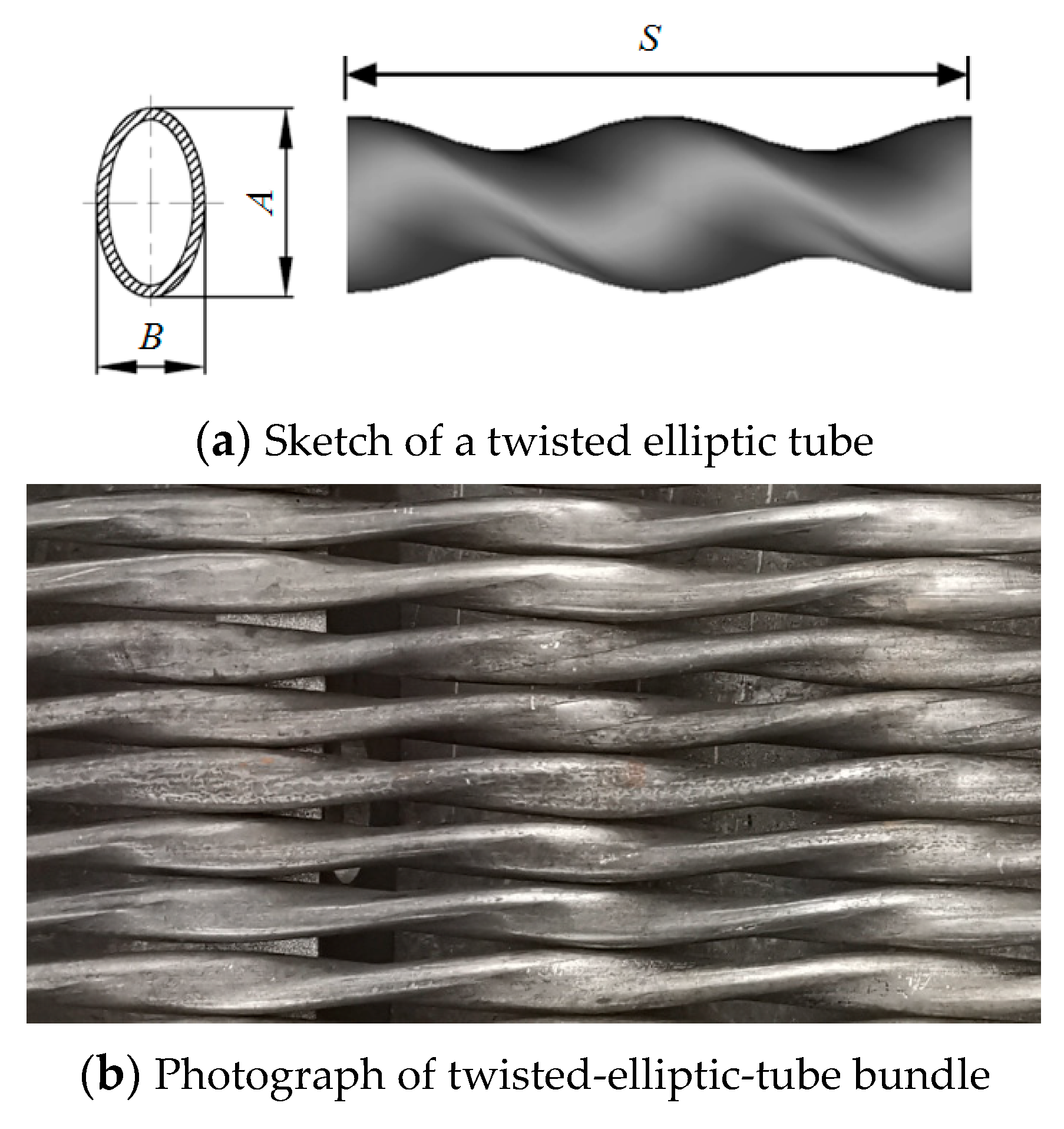
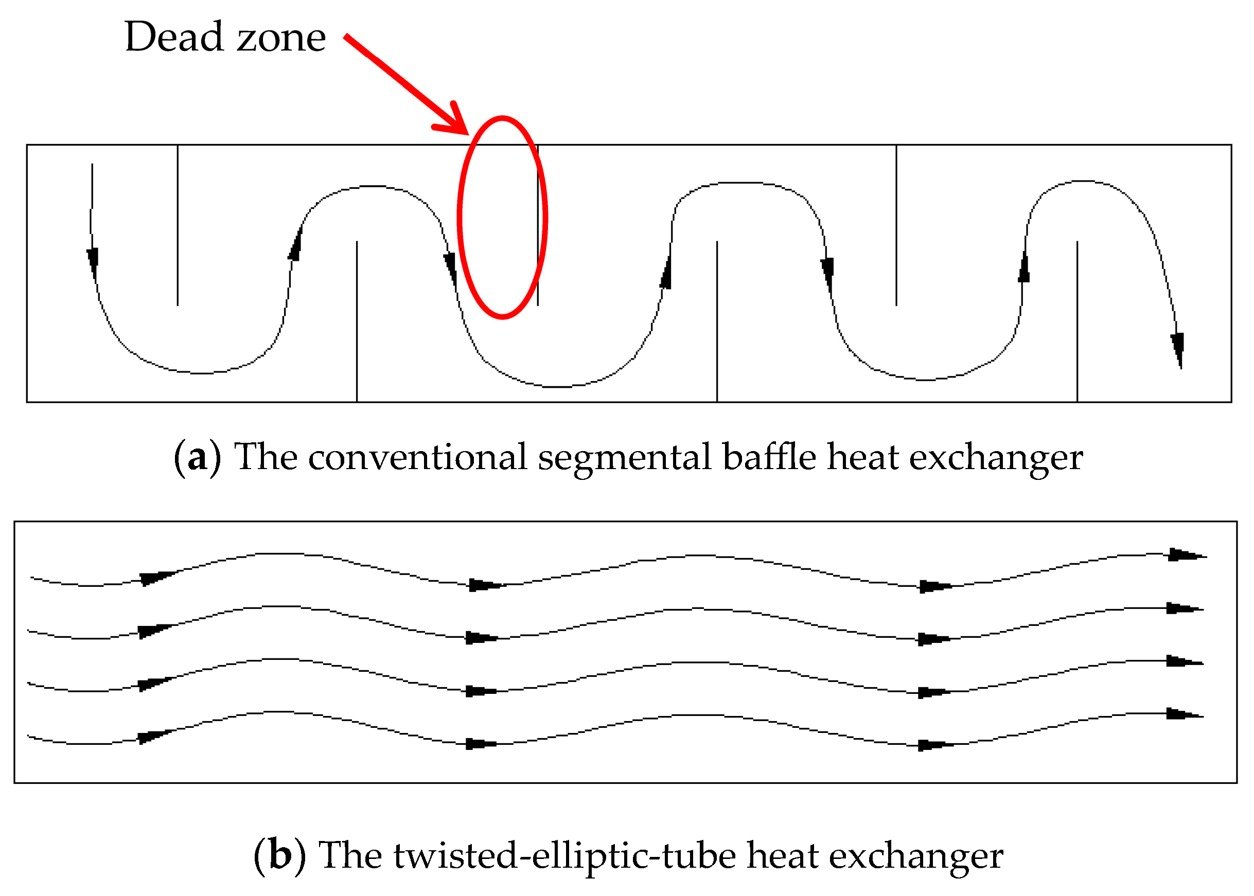
2. The Structure and Characteristic of Twisted-Elliptic-Tube Heat Exchanger
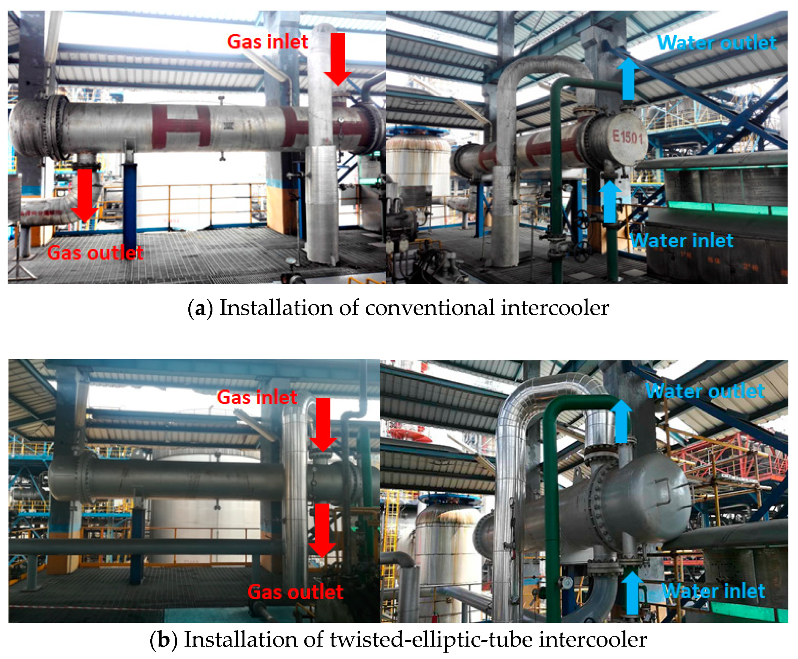
3. Description of Existing Rich-Gas-Compressor Intercooler
4. Description of a Novel Twisted-Elliptic-Tube Intercooler
4.1. Feasibility
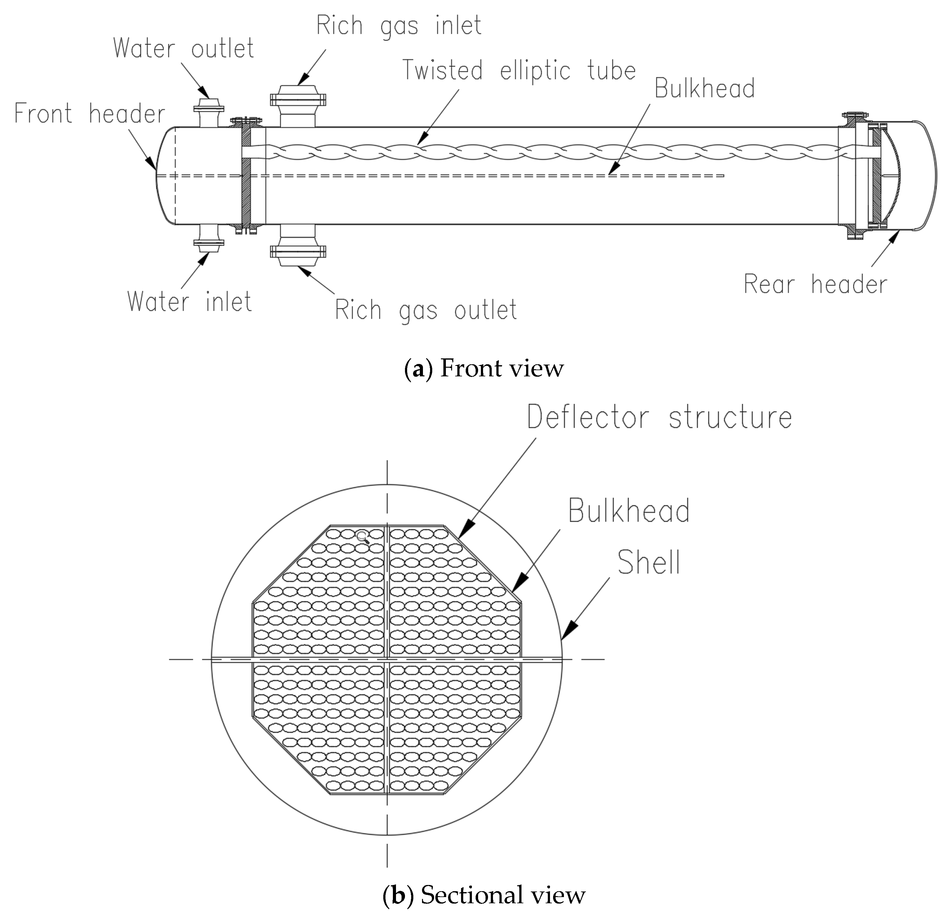
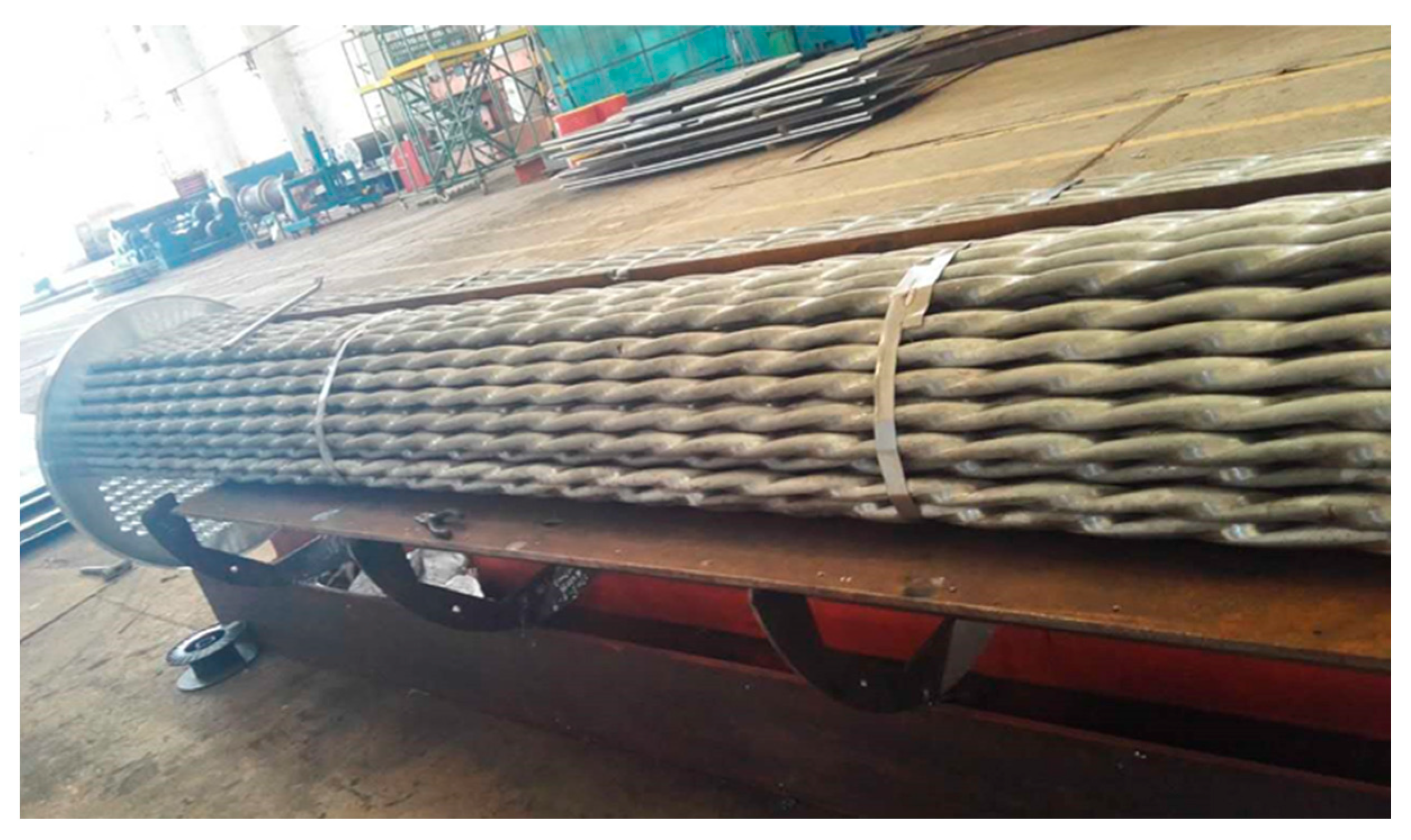
4.2. Configuration
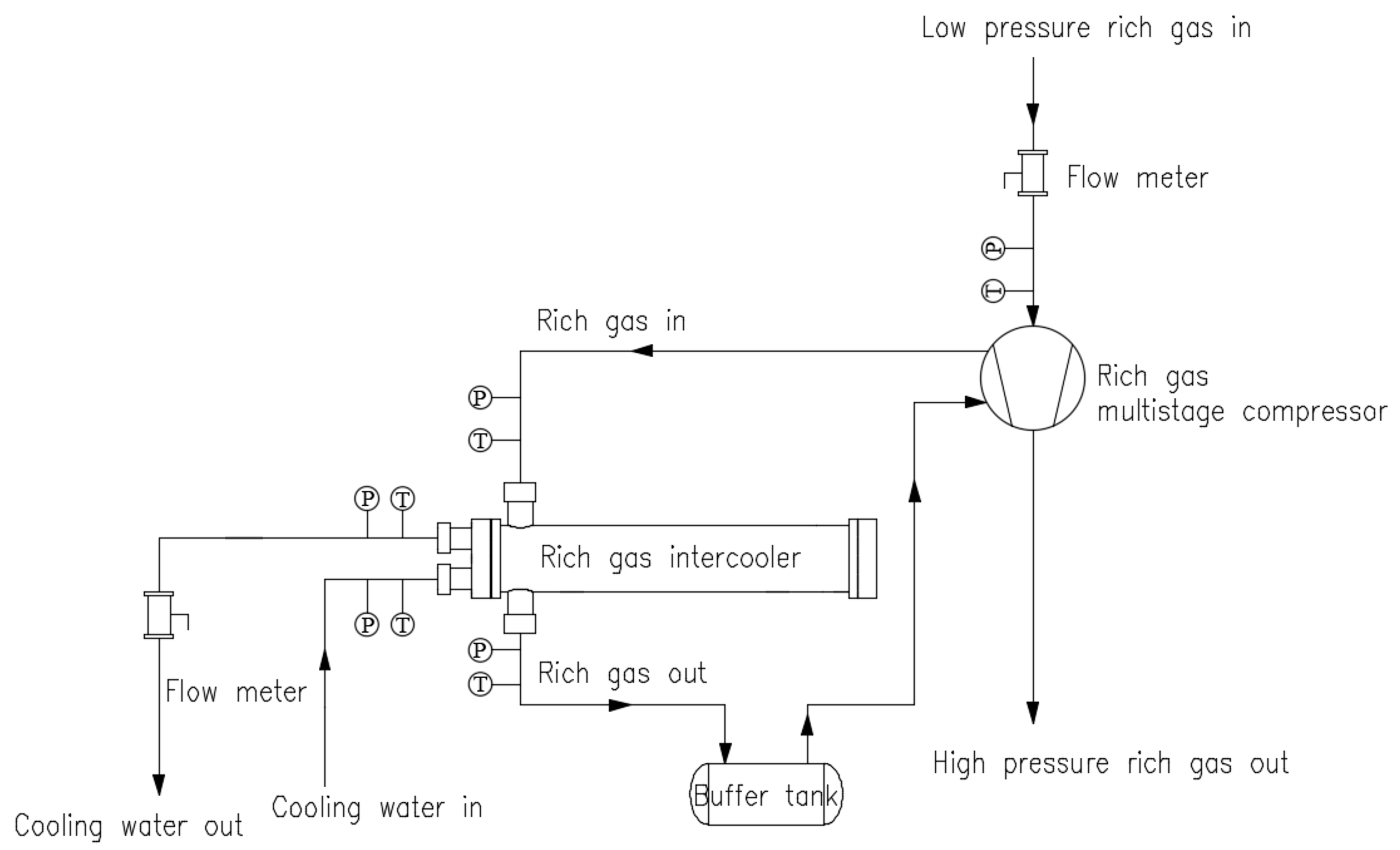
5. Industrial Locale Experimental Setup and Measurement Method
6. Data Reduction
7. Results and Discussions
8. Conclusions
- (1)
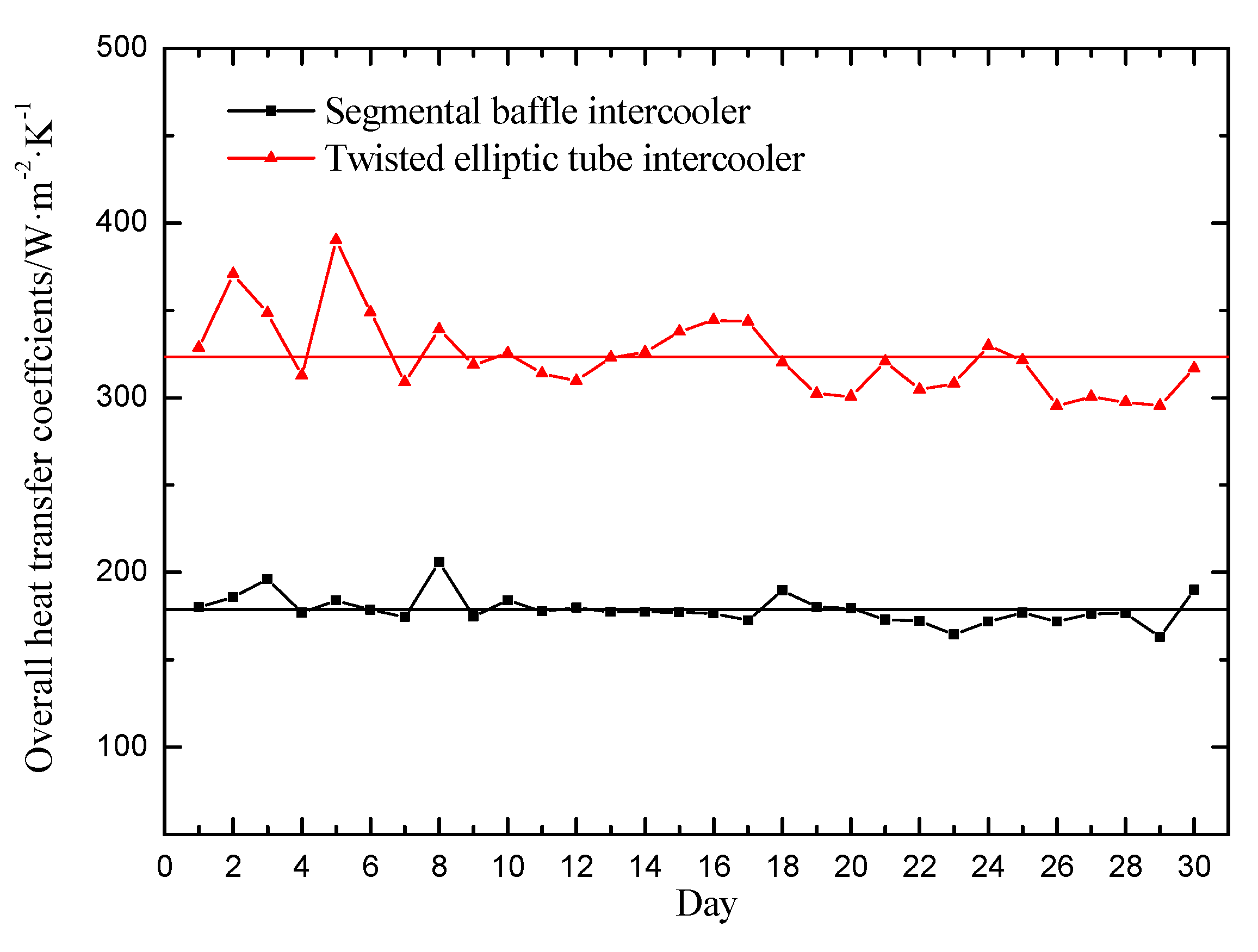
- Compared with the conventional intercooler, the twisted-elliptic-tube intercooler has a higher cooling capacity by an increase of 13.2%. Under the same operating conditions, the overall heat-transfer coefficients enhance by 87.8%. And the heat-transfer area and gas pressure drop are reduced by 37.4% and 36.9%, respectively.
- (2)
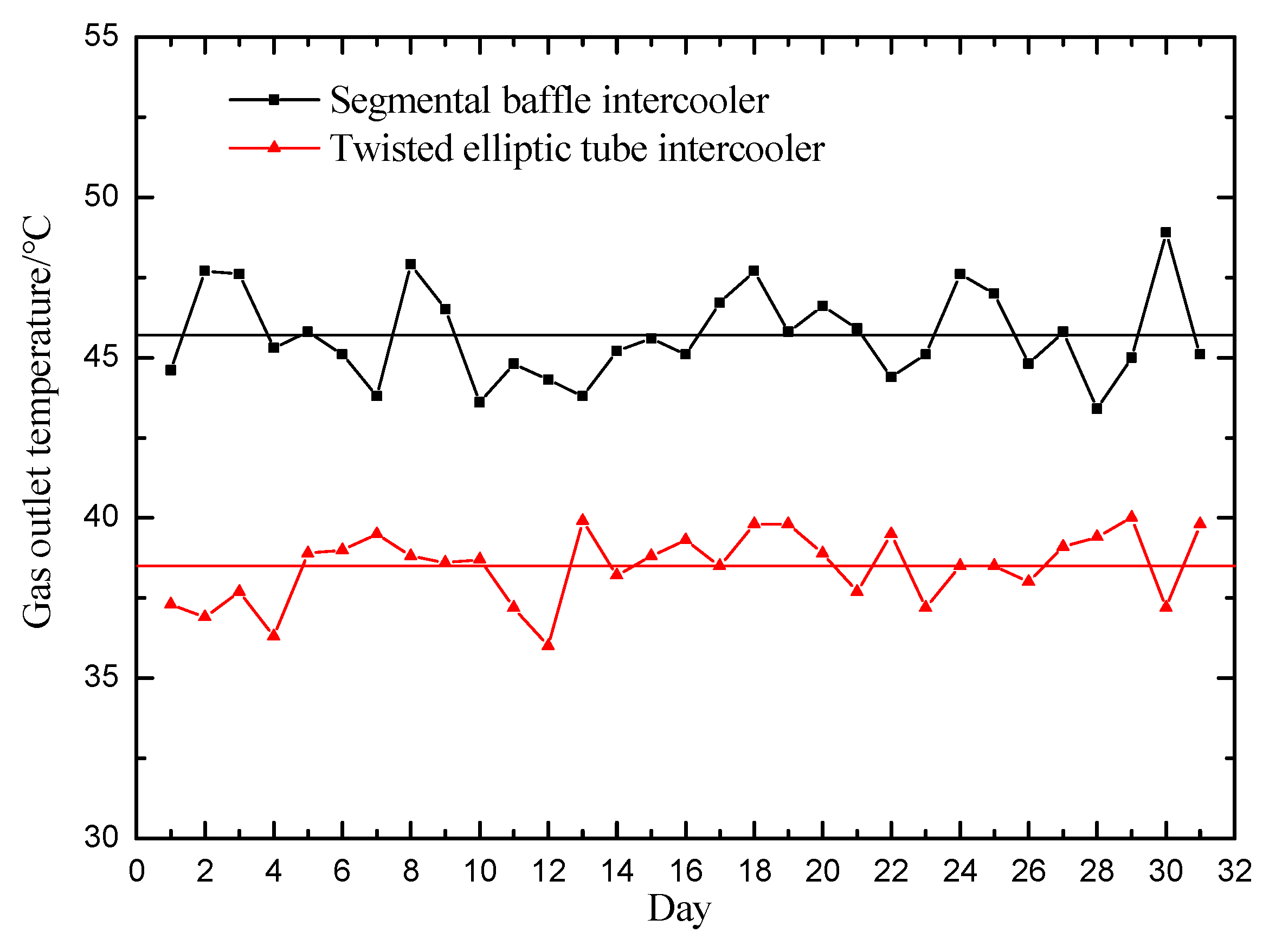
- The tube bundles’ vibration and loud noise problem of the segmental baffle intercooler are eliminated by the use of the twisted-elliptic-tube intercooler. The average outlet temperature of the rich gas is 38.4 °C and meets the design requirement well, which is 7.3 °C lower than that of the conventional intercooler. The twisted-elliptic-tube intercooler can improve the safety and efficiency of the gas compressor.
- (3)
- An application of this innovative twisted-elliptic-tube intercooler could result in considerable benefits in terms of good anti-vibration, a higher heat-transfer coefficient, lower shell-side pressure drop and material saving.
Author Contributions
Funding
Data Availability Statement
Conflicts of Interest
References
- Master, B.I.; Chunangad, K.S.; Pushpanathan, V. Fouling mitigation using helixchanger heat exchangers. In Proceedings of the ECI Conference on Heat Exchanger Fouling and Cleaning: Fundamentals and Applications, Santa Fe, NM, USA, 18–22 May 2003; pp. 317–322. [Google Scholar]
- Rezaei, M.; Mahidashti, Z.; Eftekhari, S.; Abdi, E. A corrosion failure analysis of heat exchanger tubes operating in petrochemical refinery. Eng. Fail. Anal. 2021, 119, 105011. [Google Scholar] [CrossRef]
- Yang, Y.C.; Zou, H.M.; Gu, X.; Yang, T.Y.; Tian, C.Q. Thermal-hydraulic performance of super-amphiphobic louver-fin flat-tube heat exchanger under fouled condition. Appl. Therm. Eng. 2023, 233, 121142. [Google Scholar] [CrossRef]
- Lin, P.S.; Wang, S.P.; Deng, X.H. Research progress of gas compressor cooler. Compress. Technol. 1998, 3, 17–20. (In Chinese) [Google Scholar]
- Kakac, S.; Bergles, A.; Mayinger, F. Heat Exchangers: Thermal-Hydraulic Fundamentals and Design; McGraw-Hill: New York, NY, USA, 1981. [Google Scholar]
- Ali, A.A.; Moradi, R. Shell and tube heat exchanger optimization using new baffle and tube configuration. Appl. Therm. Eng. 2019, 157, 113736. [Google Scholar]
- Milani, S.K.; Mamourian, M.; Abolfazli, E.J. Experimental study on thermal analysis of a novel shell and tube heat exchanger with corrugated tubes. J. Therm. Anal. Calorim. 2019, 138, 1583–1606. [Google Scholar] [CrossRef]
- Marzouk, S.A.; Abou Al-Sood, M.M.; El-Said, E.M.S.; El-Fakharany, M.K. A comprehensive review of methods of heat transfer enhancement in shell and tube heat exchangers. J. Therm. Anal. Calorim. 2023, 148, 7539–7578. [Google Scholar] [CrossRef]
- Akbarzadeh, S.; Valipour, M.S. Experimental study on the heat transfer enhancement in helically corrugated tubes under the non-uniform heat flux. J. Therm. Anal. Calorim. 2020, 140, 1611–1623. [Google Scholar] [CrossRef]
- Senthil, K.N.; Dhinakarraj, C.K.; Deepanraj, B.; Manikandan, B.N.; Santhoshkumar, A. Modification and analysis of compressor intercooler fin in turbocharger using FEM. Procedia Eng. 2012, 38, 379–384. [Google Scholar]
- Sathyaraj, A. Analysis and performance enhancement of intercooler in two stage reciprocating air compressor using CFD. Int. J. Appl. Mech. Prod. Eng. 2015, 1, 1–5. [Google Scholar]
- Chen, J.X.; Tan, Y.F. Experimental research of the use of stainless steel corrugated tubes for a compressor intercooler. J. Eng. Therm. Energy Power 2001, 16, 635–636. (In Chinese) [Google Scholar]
- Yu, C.; Zhang, W.; Xue, X.; Lou, J.; Lao, G. Analysis of water-cooled intercooler thermal characteristics. Energies 2021, 14, 8332. [Google Scholar] [CrossRef]
- Luo, Z.X.; Lu, X.M. Characteristics and prospect of geothermal industry in China under the “dual carbon” target. Energy Geosci. 2023, 100199. [Google Scholar] [CrossRef]
- Jiang, B.H.; Raza, M.Y. Research on China’s renewable energy policies under the dual carbon goals: A political discourse analysis. Energy Strategy Rev. 2023, 48, 101118. [Google Scholar] [CrossRef]
- Jia, X.P.; Zhang, Y.M.; Tan, R.R.; Li, Z.W.; Wang, S.Q.; Wang, F.; Fang, K. Multi-objective energy planning for China’s dual carbon goals. Sustain. Prod. Consum. 2022, 34, 552–564. [Google Scholar] [CrossRef]
- Taborek, J.; Aurioles, G. Effect of 1988 TEMA standers on mechanical and thermo-hydraulic design of shell and tube heat exchangers. AIChE Symp. Ser. 1989, 85, 79–83. [Google Scholar]
- Asmantas, L.A.; Nemira, M.A.; Trilikauskas, V.V. Coefficients of heat transfer and hydraulic drag of a twisted oval tube. Heat Transf. Sov. Res. 1985, 17, 103–109. [Google Scholar]
- Dzyubenko, B.V. Estimation of the thermohydraulic efficiency of heat exchanging apparatuses with twisted tubes. Heat Transf. Res. 2006, 37, 349–363. [Google Scholar] [CrossRef]
- Tan, X.H.; Zhu, D.S.; Zhou, G.Y.; Zeng, L.D. Experimental and numerical study of convective heat transfer and fluid flow in twisted oval tubes. Int. J. Heat Mass Transf. 2012, 55, 4701–4710. [Google Scholar] [CrossRef]
- Bishara, F.; Jog, M.A.; Manglik, R.M. Computational simulation of swirl enhanced flow and heat transfer in a twisted oval tube. J. Heat Tranfer 2009, 131, 080902. [Google Scholar] [CrossRef]
- Yan, W.B.; Gao, X.N.; Xu, W.D.; Ding, C.; Luo, Z.G.; Zhang, Z.G. Heat transfer performance of epoxy resin flows in a horizontal twisted tube. Appl. Therm. Eng. 2017, 127, 28–34. [Google Scholar] [CrossRef]
- Dzyubenko, B.V. Heat exchanger along the initial segment in a heat exchanger with a helical flow. J. Eng. Phys. Thermophys. 1982, 42, 153–157. [Google Scholar] [CrossRef]
- Liu, S.J.; Yin, Y.D.; Tu, A.M.; Zhu, D.S. Experimental investigation on shell-side performance of a novel shell and tube oil cooler with twisted oval tubes. Int. J. Therm. Sci. 2020, 152, 106290. [Google Scholar] [CrossRef]
- Mo, X.; Liu, S.J.; Li, X.Z.; Tu, A.M.; Zhu, D.S. Study on Comprehensive Performance of Three-Dimensional Tube Applied to Gas–Solid Two-Phase Flow Environment. Energies 2021, 14, 5274. [Google Scholar] [CrossRef]
- Al-Hadhrami, L.M.; Ahmad, A.; Al-Qahtani, A. Performance analysis of heat exchangers of an existing naphtha hydrotreating plant: A case study. Appl. Therm. Eng. 2010, 30, 1029–1033. [Google Scholar] [CrossRef]
- Tu, A.M.; Liu, S.J.; Mo, X.; Chen, E.X.; Zhan, X.F.; Zhu, D.S. Experimental Study of a Novel Non-Packing Closed Evaporative Cooling Tower with Vertical 3D Deformation Tubes. Energies 2022, 15, 9336. [Google Scholar] [CrossRef]
- Li, X.Z.; Wang, L.; Feng, R.; Wang, Z.W.; Liu, S.J.; Zhu, D.S. Study on shell side heat transport enhancement of double tube heat exchangers by twisted oval tubes. Int. Commun. Heat Mass Transf. 2021, 124, 105273. [Google Scholar] [CrossRef]
- Qian, S.W. Heat Exchanger Design Handbook; Chemical Industry Press: Beijing, China, 2002. [Google Scholar]
- Moffat, R.J. Describing the uncertainties in experimental results. Exp. Therm. Fluid Sci. 1988, 1, 3–17. [Google Scholar] [CrossRef]
- Kline, S.J.; McClintock, F.A. Describing uncertainties in single-sample experiments. Mech. Eng. 1953, 75, 3–8. [Google Scholar]
- Ding, Z.Y.; Xu, L.; Liu, D.W.; Yang, Y.; Yang, J.H.; Tang, D. Influence of support gap on flow induced vibration of heat exchange tube. Ann. Nucl. Energy 2023, 180, 109443. [Google Scholar] [CrossRef]


| No. | Item | Shell Side | Tube Side |
|---|---|---|---|
| 1 | Medium | Rich gas | Water |
| 2 | Volume flow rate/Nm3/h | 13,000 | - |
| 3 | Operating pressure/MPa | 0.5 | 0.35 |
| 4 | Inlet temperature/°C | 120 | 32 |
| 5 | Outlet temperature/°C | ≤40 | 42 |
| 6 | Pressure drop allowed/kPa | 40 | 50 |
| Item | Conventional Circular-Tube Intercooler | Twisted-Elliptic-Tube Intercooler | |
|---|---|---|---|
| Shell parameters | Exterior size/mm | Փ 900 × 7100 | Փ 900 × 7100 |
| Material | carbon steel | carbon steel | |
| Shell pass | 1 | 2 | |
| Tube parameters | Tube type | twisted elliptic tube | circular tube |
| do/di/mm | 20/15 | 32/27 | |
| A/B/mm | / | 36/22 | |
| Length | 6000 | 6000 | |
| Tube count | 726 | 264 | |
| Layout | 60° | 90° | |
| Tube pitch | 36 | ||
| Material | 316 L | 316 L | |
| Tube pass | 6 | 4 | |
| Baffle parameters | Spacing/mm | 490 | / |
| No. | Item | Conventional Circular-Tube Intercooler | Twisted-Elliptic-Tube Intercooler | Difference |
|---|---|---|---|---|
| 1 | Overall heat transfer coefficients/W·m−2·K−1 | 170.5 | 320.2 | +87.8% |
| 2 | Heat-transfer area/m2 | 273.6 | 171.2 | −37.4% |
| 3 | Tube-side pressure drop/kPa | 14.6 | 20.4 | +39.7% |
| 4 | Shell-side pressure drop/kPa | 42.3 | 26.7 | −36.9% |
Disclaimer/Publisher’s Note: The statements, opinions and data contained in all publications are solely those of the individual author(s) and contributor(s) and not of MDPI and/or the editor(s). MDPI and/or the editor(s) disclaim responsibility for any injury to people or property resulting from any ideas, methods, instructions or products referred to in the content. |
© 2023 by the authors. Licensee MDPI, Basel, Switzerland. This article is an open access article distributed under the terms and conditions of the Creative Commons Attribution (CC BY) license (https://creativecommons.org/licenses/by/4.0/).
Share and Cite
Liu, S.; Tu, A.; Li, Y.; Zhu, D. Optimization Design and Comparative Analysis of Enhanced Heat Transfer and Anti-Vibration Performance of Twisted-Elliptic-Tube Heat Exchanger: A Case Study. Energies 2023, 16, 6336. https://doi.org/10.3390/en16176336
Liu S, Tu A, Li Y, Zhu D. Optimization Design and Comparative Analysis of Enhanced Heat Transfer and Anti-Vibration Performance of Twisted-Elliptic-Tube Heat Exchanger: A Case Study. Energies. 2023; 16(17):6336. https://doi.org/10.3390/en16176336
Chicago/Turabian StyleLiu, Shijie, Aimin Tu, Yufei Li, and Dongsheng Zhu. 2023. "Optimization Design and Comparative Analysis of Enhanced Heat Transfer and Anti-Vibration Performance of Twisted-Elliptic-Tube Heat Exchanger: A Case Study" Energies 16, no. 17: 6336. https://doi.org/10.3390/en16176336
APA StyleLiu, S., Tu, A., Li, Y., & Zhu, D. (2023). Optimization Design and Comparative Analysis of Enhanced Heat Transfer and Anti-Vibration Performance of Twisted-Elliptic-Tube Heat Exchanger: A Case Study. Energies, 16(17), 6336. https://doi.org/10.3390/en16176336