Review

Studies on Flow Characteristics of Gas–Liquid Multiphase Pumps Applied in Petroleum Transportation Engineering—A Review

1
College of Water Resources and Civil Engineering, China Agricultural University, Beijing 100083, China
2
Beijing Engineering Research Center of Safety and Energy Saving Technology for Water Supply Network System, China Agricultural University, Beijing 100083, China
3
State Key Laboratory of Hydroscience and Engineering, Department of Energy and Power Engineering, Tsinghua University, Beijing 100084, China
*
Author to whom correspondence should be addressed.
Energies 2023, 16(17), 6292; https://doi.org/10.3390/en16176292
Submission received: 12 July 2023 / Revised: 1 August 2023 / Accepted: 11 August 2023 / Published: 29 August 2023
(This article belongs to the Special Issue Recent Studies on Fluid Dynamics Applied in Energy Systems)

Abstract

:
Flow and phase separation in gas–liquid multiphase pumps is easy to occur, which deteriorates their performance and mixed transportability. Many research achievements have been made in the experiment, CFD simulation and performance improvement of multiphase pumps. However, there are many challenges for the test technology, accurate numerical model development and gas–liquid flow control. This paper is mainly aimed at critically reviewing various technologies for experimental observation, flow calculation and analysis, and the optimization design of gas–liquid multiphase pumps. In this regard, the experimental results including the energy performance, flow pattern and bubble movement in the multiphase pump are presented in detail. Discussions on the turbulence model, multiphase flow model and bubble balance model are carried out for the flow prediction in such pumps. Various numerical results are presented, including energy performance, bubble distribution, vorticity, phase interaction and pressure fluctuation. Moreover, the flow control and optimization strategy are briefly introduced. Having carried out an extensive literature review of flow characteristics in multiphase pumps, the deficiencies of relevant fields and suggestions for future research direction are given.

1. Introduction

Oil and gas are important non-renewable resources, which support the development of the world’s economy. The “BP Statistical Review of World Energy 2021” reports that the global oil discovered reserves increased from 2012 to 2020, but global oil production declined in general [1].
In the process of oil resource development, a mixture of oil, gas, water and impurities directly extracted from oil wells need to be transported. The transportation model includes traditional separated transportation and mixed transportation. The former transports the extracted media separately through the separation system. The latter uses a multiphase pump to replace the oil pump and compressor, which saves the complicated separation equipment. Moreover, there is no need to lay two separate sets of gas and liquid transmission pipelines because of the shared oil and gas transportation pipeline. Therefore, compared with traditional separated transportation, the mixed transportation mode could improve transportation efficiency and reduces investment costs [2,3,4].
The gas–liquid multiphase pump is the key equipment in the multiphase transport of oilfield resource development [5,6]. The pump types mainly include the positive displacement pump and the vane pump [7]. The former is represented by the screw pump [8,9,10], which transports media through the volume variation between the mutually engaged screws. The latter is represented by the helical axial vane pump. Its working mode makes the medium obtain kinetic energy through the high-speed rotation of the impeller and convert it into pressure energy when passing through the guide vane [11,12]. Compared with the positive displacement pump, the vane pump has some advantages, such as large delivery flow, small volume, low manufacturing accuracy requirement and low sensitivity to solid particles [11,13,14].
Due to the existence of the gas phase, the flow in the multiphase pump is very complicated, accompanied by obvious flow separation and phase separation. Therefore, the energy performance of multiphase pumps is seriously worse than that of the single-phase flow pump [15,16]. The experiment is an effective means to obtain the energy performance and flow characteristics of multiphase pumps. The external characteristics of the pump under different conditions of rotating speeds, inlet gas void fractions (IGVFs) and flow rates can be obtained through performance testing. The flow pattern and flow parameters in the pump can be obtained using high-speed photography, PIV technology, LDV technology and high-precision sensors [17,18,19,20]. Due to the complex interface effect and relative velocity, the monitoring of relevant parameters for the two-phase flow is more difficult than that of the single-phase flow. Therefore, how to accurately measure gas–liquid flow parameters has become the major challenge in the experiment of multiphase pumps. Meanwhile, the pressure balance and uniform mixing between two phases should be ensured in the experiment, but in fact, it is difficult to achieve, especially for high IGVFs. Therefore, how to ensure the stability of test conditions is another important problem [21].
CFD simulation is widely adopted to predict the energy performance and internal flow of multiphase pumps due to its advantages of a short calculation period and low cost [22,23,24]. The stability of boundary conditions can be guaranteed in the CFD simulation. The energy performance, pressure fluctuation and gas–liquid flow characteristics could be obtained using CFD methods [25]. Moreover, the gas–liquid phase interaction information could be obtained with CFD methods, but it is difficult to achieve in the experiment [26,27,28]. Nevertheless, the CFD simulations of the gas–liquid multiphase pump are not flawless. The reliability and robustness of the turbulence model and phase interaction model need to be improved. The existing numerical model can only meet the requirements of CFD simulation for the multiphase pump with low IGVFs, but not for high IGVFs. As the IGVF is high, the gas–liquid phase separation and flow separation in the pump are more serious, resulting in the emergence of composite flow patterns with different mechanisms of formation, division and transition [27,29].
Due to the complexity of gas–liquid flow, the design of multiphase pumps has more requirements than single-phase flow pumps. It not only needs to avoid obvious phase separation and flow separation, but also needs to ensure strong pressurization capacity and high efficiency under conditions of high IGVFs. Unfortunately, limited by the design theory and calculation ability, the existing design methods cannot achieve the design of the multiphase pump with high energy performance and good transportability [13]. Therefore, the combination of CFD simulation and the optimization algorithm is often adopted to optimize the original multiphase pump. In the optimization design, the widely used optimization algorithms include design of experiment (DOE) [30], response surface methodology (RSM) [31,32] and multi-objective genetic optimization algorithm (MOGOA) [33]. The energy performance indicators of the pump are regarded as the optimization objectives [32], rather than the complex gas–liquid flow parameters [34]. The gas–liquid flow is not well controlled directly in the process of optimization design; thus, the energy performance of the multiphase pump has not been improved significantly.
To date, a substantial amount of research has been carried out on multiphase pumps. Some achievements have been made in the experiment, numerical model development, CFD simulation and analysis and optimization design. However, there is an absence of a single article that comprehensively summarizes the research results achieved so far. This is also the motivation for the current work. This work presents recent studies on the flow characteristics of multiphase pumps for obtaining an effective overview of the field. It is dedicated to disseminating the achievements of experimental measurement, CFD simulation and flow control of the gas–liquid multiphase pump. Firstly, the experimental results including the energy performance, flow pattern and bubble movement are introduced in detail. Secondly, a critical review of CFD simulations is carried out. It includes the turbulence model, multiphase flow model, bubble balance model, energy performance, flow characteristics, phase interaction and flow improvement strategy. Finally, a summary of the investigated literature, important findings and future directions is provided.

2. Multiphase Pump Type

The multiphase pump can be divided into a positive displacement pump and a vane pump. Table 1 shows the various types of multiphase pumps applied in the United States, Britain, Germany, Japan, China and Russia [35]. Table 2 shows the merit and defect of all types of multiphase pumps [35].
Table 1. Types of oil and gas multiphase pumps chosen by countries adapted from Ref. [35].
United StatesBritainGermanyJapanChinaRussia
Screw pumpScrew pumpScrew pumpCentrifugal pumpScrew pumpScrew pump
Liquid-ring pumpAxial pumpVortex pumpVortex pumpLiquid-ring pumpLiquid-ring pump
Centrifugal pump//Screw pump//
Table 2. Merit and defect of all types of the multiphase pump adapted from Ref. [35].
TypesMultiphase Pump
MeritDefect
Screw pumpHigh pressure (up to (5~12) × 105 Pa)
High efficiency (20~50%)
Large discharge capacity
Simple structure
Small oil–gas ratio (up to 20)
Easy temperature rise
Sensitive to solid particles
High manufacturing requirements
High price
Liquid-ring pumpLarge oil–gas ratio (up to 10~1000)
Insensitive to solid particles
Low price
Low pressure
Low efficiency
Small discharge capacity (120~600 m3/h)
Axial pumpLarge discharge capacity (1500 m3/h)
High efficiency
Simple structure
High pressure with a few units
Small oil–gas ratio (up to 10)
performance deteriorates with the increased oil–gas ratio
Centrifugal pumpHigh pressure
Large discharge capacity
Simple structure
Easy manufacturing
Low price
High efficiency
Small gas–liquid ratio
Vortex pumpLarge discharge capacitySmall gas–liquid ratio (up to 10)
Low efficiency
Complex structure
The positive displacement pump is represented by the screw pump, which is the main pressure-boosting equipment for mixed transportation in all major oilfields [36]. It can be mainly classified into the single-screw pump and twin-screw pump based on the number of mutually engaged screws [37]. The vane pump is represented by the helical axial multiphase pump, which mainly includes the supercharging unit, axial force balancing device, cooling system, sealing system and bearing support structure. Figure 1 and Figure 2 show the structure of the twin-screw pump [9] and helical axial multiphase pump [38], respectively.

3. Experimental Studies of Multiphase Pumps

The experiment is an effective means to obtain the energy performance and flow characteristics of the multiphase pump. It can provide basic data for the validation of CFD numerical methods.

3.1. Energy Performance Testing

The efficiency and head of the multiphase pump are important indicators to evaluate the level of hydraulic design. Through performance testing, the efficiency and head of the pump can be acquired under different conditions of IGVFs, rotating speeds and flow rates [17]. Xu et al. [39] conducted an experiment for a helical axial multiphase pump under different IGVFs. They found that the variation trend of the pump’s performance is similar to that at pure water conditions when the IGVF is lower than 15%. Moreover, the pump can operate stably at IGVF = 50% and be sustained momentarily at IGVF = 100%. When the IGVF becomes higher, the efficiency and head of the pump decrease. The hydraulic performance of the pump with different IGVFs is shown in Figure 3.
The variation in energy performance is closely correlated with the internal flow in the multiphase pump [18,40,41,42]. Bratu [41] conducted an experiment on the efficiency, operating stability and safety margin of Poseidon pump P300. The pump efficiency reduces significantly when the GVF oscillates and the slug flow pattern occurs. Zhao et al. [40] obtained the connection between flow pattern and energy performance through an experiment of a centrifugal pump at gas–liquid flow conditions, as shown in Figure 4. The pressurization and efficiency of the pump are almost unchanged by the entrained bubbles at the bubbly flow pattern. However, when the flow pattern is converted to agglomerated bubble flow and gas pocket flow, they decrease with the increase in IGVFs. Their downward trend becomes significant at the segregated flow pattern and a surge will occur in the pump.

3.2. Flow Patterns

One purpose of the experiment for the multiphase pump is to investigate the internal flow pattern. The flow pattern occurring in the pump depends on various factors such as the flow rate and physical properties of each phase, operating conditions and geometric structure [43,44]. The variation in flow pattern will make a great difference in the energy performance and transportability of the pump. Therefore, it is very important to explore the formation and transition mechanism of the flow pattern in the multiphase pump [45].
High-speed photography is usually applied to investigate various flow patterns in the gas–liquid multiphase pump. The isolated bubble flow, bubble flow, gas pocket flow and separated gas flow have been obtained using experimental observation and their characteristics have been summarized in detail [17,46,47]. Figure 5 shows four flow patterns observed in the first stage of a multiphase rotodynamic pump [17].
The flow patterns may be different in the impeller and guide vane of the multiphase pump. Cubas et al. [48] observed the flow characteristics in a radial centrifugal pump. They found that various flow patterns appear in the impeller, such as bubble flow, agglomerated bubble flow, gas pocket flow and annular flow, as shown in Figure 6. However, there is only one flow pattern in the guide vane for the whole range of tested operating conditions.

3.3. Bubble Motion

The motion and distribution of bubbles in the multiphase pump are complex due to the high-speed rotation of the impeller and the rotor–stator interaction [12,25,49]. Through the experimental technology, not only the flow pattern, but also the law of bubble movement and distribution in the multiphase pump could be obtained.
The bubble size is an important factor that affects the energy performance of the multiphase pump. As the IGVF increases and the rotating speed decreases, the bubble size usually becomes large, as shown in Figure 7 [50]. In addition, Zhang et al. [50] obtained a normal distribution of bubble size at the pump inlet by post-processing the high-speed photographic images of internal flow, as shown in Figure 8.
Figure 9 shows the bubble distribution in a multiphase rotodynamic pump at different IGVFs, which is obtained by high-speed technology [51]. Regardless of IGVFs (3%, 9%, 15%, 21%), the gas mainly gathers close to the impeller outlet and the blade suction surface. As the IGVF increases, the degree of gas accumulation in the impeller and guide vane becomes higher, as marked by yellow and red circles in Figure 9d. The law of bubble motion is similar at different IGVFs, as shown in Figure 10. The bubbles in the impeller move from the blade pressure surface to the blade suction surface along a similar path, and their sizes become smaller as they hit the blade wall.

4. Numerical Methods on Flow Mechanism

As computer technology and numerical algorithms advance, CFD technology becomes popular for flow calculation in the multiphase pump. It can eliminate the limitations of test conditions and test technology and provide an efficient means to comprehensively obtain the internal flow characteristics in the multiphase pump.

4.1. Turbulence Model

The turbulence model is the key factor that affects the accuracy of CFD simulation for multiphase pumps, but there is no unified model [52,53]. At present, the two-equation models are usually adopted to predict the gas–liquid flow in the pump, which includes k-ε [25,54,55,56], RNG k-ε [57,58,59] and SST k-ω [27,60,61,62,63] models. The information on these three turbulence models and their application to the flow prediction in the multiphase pump are summarized in Table 3 [64].
The k-ε model was proposed by Launder and Spalding in 1972 [65]. This model has a good prediction for the overall flow in the pump, but not for the large curvature and separated flow due to the neglect of turbulence anisotropy. According to renormalization group theory, Yakhot and Orszag established the RNG k-ε model in 1986 that could better solve the flow with a large curvature, strong rotation and high strain rate [66]. The SST k-ω model was developed by Menter, which combines the Wilcox k-ω model with the standard k-ε model [67]. The SST k-ω model has both the advantages of the Wilcox k-ω model in the near-wall region and the k-ε model in free shear layers.
Table 3. Turbulence models applied in multiphase pumps reprinted with permission from Ref. [64].
Turbulence ModelAuthorObjectMain Conclusion
k-εZhu et al. (2017) [68]Three-stage centrifugal ESPThe relationship between bubble size and GVF is determined.
He et al. (2020) [57]Centrifugal pumpThere is a great scattering of the void fraction at high-rotation speeds.
Caridad et al. (2008) [55]Centrifugal pumpThe gas pocket increases hydraulic losses.
Pineda et al.
(2016) [56]
Centrifugal ESPThe head decreases at higher gas flow rates and lower intake pressures.
RNG k-εMa et al. (2020) [58]Reciprocating multiphase pumpThe instantaneous two-phase distribution and fluctuation characteristics at high GVFs are determined.
Liu et al. (2020) [59]Three-stage helico-axial multiphase pumpIncreases in viscosity and blade height as well as decreases in flow rate increase turbulent kinetic energy.
SST k-ωKim et al. (2015) [60]Helico-axial multiphase pumpHydrodynamic performance is improved by an optimization design method.
Yu et al. (2015) [27]Axial multiphase pumpDrag force is dominant and turbulent dispersion force can be neglected.
Stel et al. (2015) [61]Mixed-type ESPPressure difference and flow pattern are obtained at different flow rates.
Pervaiz et al. (2022) [62]Centrifugal pumpTurbulence increases with the increase in GVF in the impeller.
Shu et al. (2022) [63]Helico-axial multiphase pumpThe relationship between vorticity and enstrophy dissipation rate is obtained.

4.2. Turbulence Model Two-Phase Flow Model

The two-phase flow model is also important in determining the numerical accuracy of the flow prediction in the multiphase pump [69]. It is mainly divided into the Euler–Lagrange model and the Euler–Euler model. The former is represented by the discrete phase model [70], which can more easily obtain the velocity and motion trajectory of the discrete phase. The latter has mainly experienced the development of the homogeneous model, diffusion model and two-fluid model [71]. In the homogeneous model, the two media are equivalent to a pure substance. The precondition is that the kinetic and thermodynamic properties of the two uniformly mixed media are similar or their velocity difference is small [72]. The diffusion model is used to describe the motion of a binary mixture and the variation in flow parameters, which combines the average motion and diffusion motion of the mixture [71]. The two-fluid model is widely applied in the flow prediction of multiphase pumps because of its relatively high calculation accuracy [27,73,74]. In this model, each medium has its conservation equations, which are coupled together through phase interactions [75]. The detailed comparison between the Euler–Lagrange model and the Euler–Euler model is shown in Table 4.
Table 4. Numerical methods for gas–liquid two-phase flow.
Numerical MethodsTwo-Phase Flow ModelFeatureDisadvantage
Euler–Lagrange methodDiscrete phase model [70]The velocity and motion trajectory of the discrete phase are easily obtained.Suitable for IGVF of less than 10% and very low computational efficiency.
Euler–Euler methodHomogeneous model [72]The two media are equivalent to a pure substance.Ignored the phase interaction and large calculation error.
Diffusion model [71]The average motion and diffusion motion are considered.Not applicable for large diffusion speed.
Two-fluid model [27,73,74]Each medium has its conservation equations, and phase interactions are considered.Low calculation efficiency and difficulty in convergence.
The interactions between phases in multiphase flow are calculated by the phase interaction model. The interaction model of two-phase flow mainly includes drag, added mass force, turbulence dispersion force, lift, Bassett force and Magnus force. Besides the interphase forces, the inertia force and pressure difference force are acting on the bubbles. Therefore, the force balance equation acting on bubbles can be expressed as Equation (1).
F D + F L + F A + F T + F B + F M + F S + F i + F p = 0
Table 5. Information on the forces acting on bubbles.
ItemsSymbolExpression
DragFD F D = 3 4 C D ρ l d a g V g - V l V g - V l
LiftFL F L = C L α g ρ l V g - V l × N × V l
Added mass forceFA F A = - ρ l C A α g D V g D t - D V l D t
Turbulent dispersion forceFT F T = - C T ρ l k N α l
Basset forceFB F B = 3 2 d 2 ρ c π ν t 0 t ξ t t - t d t
Magnus forceFM F M = 1 8 π d 3 ρ c ω u c - u p
Staffman forceFS F S = 1 . 62 d 2 ρ c μ u c - u p d u c d y
Inertia forceFi F i = - 1 6 π d 3 ρ p d u p d t
Pressure difference forceFp F p = - 1 6 π d 3 d p d x
The information on each force is shown in Table 5. These forces are not equally important and are not necessary to be calculated completely. Therefore, it is of great significance to determine the important force through the magnitude analysis of forces.

4.3. Bubble Balance Model

Due to the high-rotational speed of impeller and rotor–stator interaction, bubbles in the pump will merge and split. Murakami and Minemura [76] adopted an empirical formula to correlate the observed bubble sizes in centrifugal pumps. Barrios [68] and Gamboa [77] developed a bubble-size prediction model from the experimental results in ESPs. Zhu et al. [25] developed a mechanistic model according to the maximum stable bubble for correlating the CFD simulated bubble sizes. The expression of the maximum bubble size is shown in Equation (2). Moreover, the accuracy of the bubble size model is verified by comparison with other models, as shown in Figure 11.
d max = C λ G W e crit 2 3 / 5 σ ρ c 3 / 5 Δ P q ρ c V - 2 / 5 ρ c ρ d 1 / 5
Our team has carried out some research on the CFD prediction of bubble size in the multiphase rotodynamic pump. According to the research results of the gas–liquid stirred tank obtained by Lane et al. [78], a conservation equation considering bubbles’ coalescence and break-up has been developed for the flow prediction in the multiphase rotodynamic pump [79]. Its accuracy is verified by comparison with the experimental data under different IGVFs, as shown in Figure 12.
n x , t t + · nU 2 = ψ br - ψ co

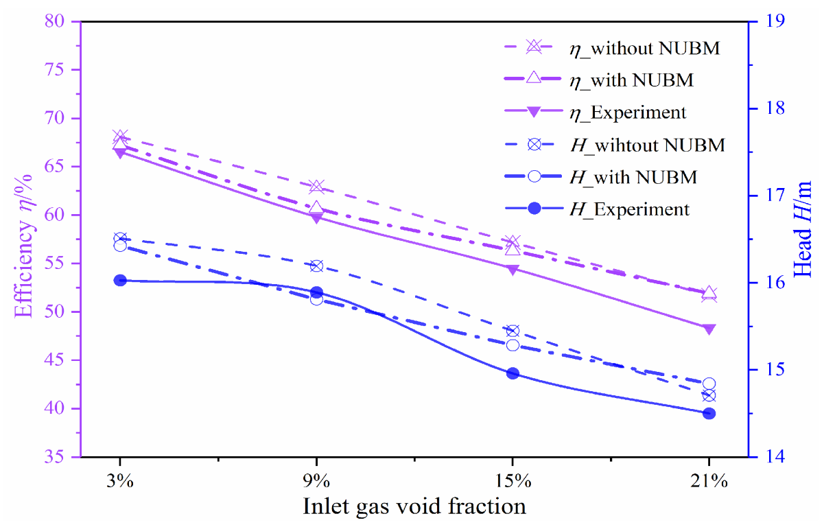
5. CFD Analysis of Energy Performance

The energy performance of the multiphase pump is crucial for evaluating its comprehensive characteristics. Due to the existence of gas, the energy performance of the multiphase pump is worse than the single-phase flow pump. Moreover, the gas content at the pump inlet is not constant during actual operation. This is the reason why the energy performance of a multiphase pump under different IGVFs is of great interest. Figure 13 shows the variation trend of the pump head with different IGVFs [79]. Regardless of the experiment and CFD simulation, the pump head decreases gradually as the IGVF increases. Especially, the pump head at IGVF = 21% is only about 91% of that at IGVF = 3%.
In the actual operation process, the multiphase pump is usually composed of different unit stages to meet the requirement of pressurization. This is the reason why the energy performance of the multistage multiphase pump is widely concerned [80]. After investigating the energy performance of a multiphase pump with three stages, Zhang et al. [73] obtained that the average static pressure decreases slightly at the rotor–stator region, but overall increases with the increased stage numbers, as shown in Figure 14.

6. CFD Analysis of Flow Characteristic

The gas–liquid phase separation is prone to occur in the multiphase pump. In fact, an air blockage may appear in the pump, which aggravates the flow separation and forms large-scale vortices [81,82]. Therefore, the energy performance and the operation stability of the pump will decrease.

6.1. Gas Distribution Law

Due to the density difference between phases, the centrifugal force of the liquid with a large density is greater than that of the gas phase, leading to the liquid and gas moving towards the shroud and hub, respectively [51]. CFD simulation is one effective method and is widely used in the flow prediction of the multiphase pump, which has the advantages of short calculation time and low cost [83].
Based on the Eulerian–Eulerian model and population balance model, He et al. [57] carried out CFD simulations for the gas–liquid flow in a centrifugal pump with the inlet bubbly flow pattern. They found that the air pocket is not completely filled with the impeller passage and some liquid exists between the rear cover and gas pocket, as shown in Figure 15. Figure 16 displays the relationship between the gas–liquid flow characteristics and the pump performance. When the IGVF is small (e.g., IGVF = 1~3%), the head and efficiency of the pump are slightly decreased. As the degree of gas accumulation increases, the pump performance decreases significantly.

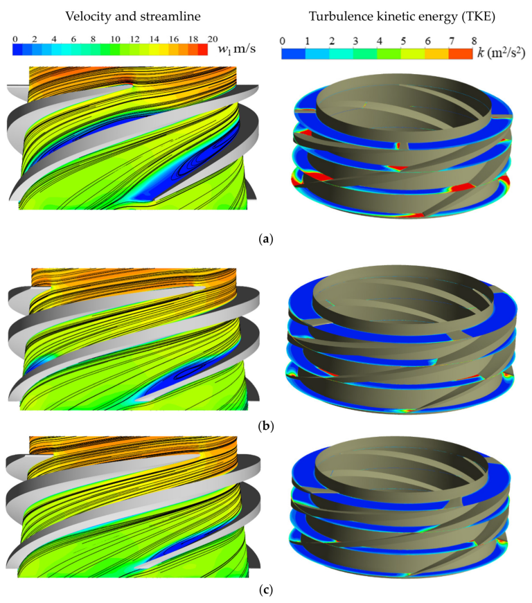
6.2. Vorticity Characteristics

The flow separation and phase separation often occur in the gas–liquid multiphase pump, which accelerates the formation and development of the vortex [81,82,84]. Zhang et al. [81] conducted a CFD simulation for the gas–liquid flow in a multiphase rotodynamic pump with two unit stages. They found that the gas strongly accumulates in the first unit stages, leading to a complex internal flow, as shown in Figure 17. Moreover, obvious flow separation and large-scale vortices occur in the guide vane.
To deeply investigate the gas–liquid flow characteristics, the Q criterion is widely used to investigate the flow structure in the multiphase pump. The expression of the Q criterion is as follows [85,86]:
Q = 1 2 ( Ω ij Ω ij - S ij S ij )
S and Ω are respectively the symmetric and anti-symmetric components of the velocity tensor matrix. They can be calculated as follows:
S = V + V t / 2
Ω = V - V t / 2
As the IGVF increases, the vortices in the pump are usually more obvious and the vortex structure becomes more complicated. Parikh et al. [24] investigated the characteristics of the vortex and wake in the impeller under different IGVFs by combining the Q criterion, as shown in Figure 18. The flow separation is obvious near the suction surface at the blade leading edge, while the weak flow separation occurs near the pressure surface at the blade trailing edge, as the marked separation vortices 1 and 2, respectively. Meanwhile, the vortex structure (black iso-surface) in the impeller becomes more obvious and more complicated with the increase in IGVFs.

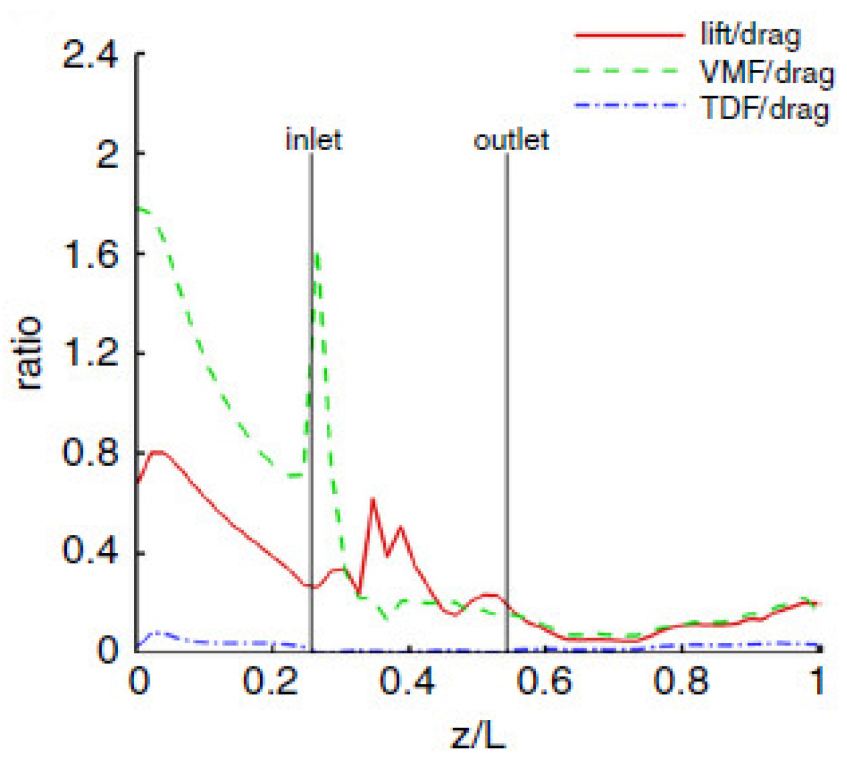
6.3. Phase Interaction Characteristics

Phase interactions are the research focus and are difficult in the field of multiphase flows. Based on current detection technology, it is difficult to obtain detailed information on the multiphase flow interface parameters using experimental methods. With the progress and development of computing technology, CFD simulation is becoming an effective way to investigate the phase interaction of multiphase flows.
The complex phase interaction mode is the fundamental reason for the complex flow in the multiphase pump. Magnus and Saffman forces are generally considered to be negligible in the multiphase rotodynamic pump [72]. The drag, added mass force, lift and turbulent dispersion force in the pump have been explored in recent years. Their magnitude and variation laws are revealed gradually. Figure 19 is the numerical results of interphase forces in the impeller of a multiphase rotodynamic pump obtained by Yu et al. [27]. It shows that the drag is most important, followed by the lift and added mass forces, while the turbulent dispersion force is the smallest and its magnitude can be ignored.
The magnitude and variation laws of interphase forces are not constant, which varies with the pump’s operation conditions and the medium characteristics. Zhang et al. [80] analyzed the interphase forces in a gas–liquid multiphase pump with two unit stages. Figure 20 shows the variation trend of interphase forces with air–water and air–oil combinations. For the air–water combination, the ratios of lift/drag (FL/FD) and added mass force/drag (FA/FD) in the rotor–stator region are larger than 1, which indicates that drag is not the dominant force herein. For the air–crude combination, the ratios of lift/drag (FL/FD) and added mass force/drag (FA/FD) are generally less than 1, which illustrates that drag plays a leading role.

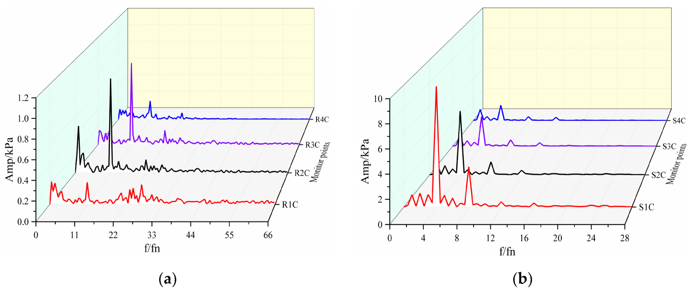
6.4. Pressure Fluctuation Characteristics

The pressure fluctuation in various types of single-phase pumps, such as centrifugal [87,88,89], axial flow [90,91,92] and mixed flow [93,94,95], has been investigated thoroughly. The relevant research results show that the rotor–stator interaction is the key factor to produce pressure fluctuation in the single-phase flow pump.
The pressure fluctuation in the gas–liquid multiphase pump is complex due to the coalescence and break-up of bubbles, the pulsation of phase content and the separation and mixing of gas–liquid phases [96]. Zhang et al. [97] analyzed the pressure fluctuation in a multiphase pump under different IGVFs. They obtained results showing that, regardless of IGVFs, the pressure fluctuation of point S1C at the guide vane inlet is the largest, as shown in Figure 21. Meanwhile, an interesting phenomenon emerges, showing that the weak pressure fluctuation of point R4C near the impeller outlet is obtained. This is attributed to the complex gas–liquid flow, therein weakening the rotor–stator interaction. Moreover, the inlet bubble diameter is another important factor that affects the pressure fluctuation in the multiphase pump. The pressure fluctuation in the pump usually increases with the increased inlet bubble diameter.

7. Flow Improvement Strategy of Multiphase Pump

At present, the mechanism of flow separation and phase separation in the gas–liquid multiphase pump is not clear enough, which is the reason why the complex gas–liquid flow cannot be controlled. Although relevant research on flow control in the multiphase pump has been widely carried out, a unified technical control strategy is absent. Generally, the current flow improvement strategies in the multiphase pump are divided two ways, i.e., indirect flow control strategy and direct flow control strategy.

7.1. Indirect Control Strategy of Gas–Liquid Flow

Due to the limitation of design theory and calculation ability, the three-dimensional inverse problem design method commonly used for the design of fluid machinery fails to directly obtain the multiphase pump with high performance. The indirect control for the gas–liquid flow in the pump is conducted by optimizing its hydraulic performance.
The combination of optimization design and CFD simulation is widely adopted to indirectly improve the gas–liquid flow in the pump. By combining Latin-hypercube sampling and response surface approximation, Suh et al. [13] carried out an optimization design on a multiphase rotodynamic pump with the objective of pump efficiency. The optimization result in Figure 22 shows that the maximum efficiency of the impeller is 77.01%.
Besides single-objective optimization, multi-objective optimization is also often widely adopted. Using the pressurization and efficiency of the pump as the optimization objectives, Zhang et al. [98] optimized a helico-axial multiphase pump by adopting an artificial neural network. After optimization, the pressurization and efficiency of the impeller are significantly improved, as shown in Figure 23. Moreover, Figure 24 shows that the gas in the impeller distributes more evenly.

7.2. Direct Control Strategy of Gas–Liquid Flow

Recently, the direct control strategy of gas–liquid flow has been applied in multiphase pumps. The pressure fluctuation, phase separation and flow separation are controlled during the optimization design of such pumps.
Liu et al. [23] optimized a multistage pump handling gas–liquid flow. Based on the Oseen vortex, a theoretical model that calculates the velocity moment downstream of the guide vane was developed. Therefore, the inlet blade angle of the later-stage impeller can be optimized using this model. Figure 25 shows that the length of the high Reynolds dissipation area at the blade leading edge is decreased significantly after optimization, which is attributed to the more matched inlet blade angle determined by the developed optimization method.
Our team has conducted some work on the direct control of gas–liquid flow in the pump [34,99]. The optimization design of an impeller was conducted with its geometry and blade-loading parameters as variables, and the pump efficiency and gas–liquid uniformity as objectives. A pump with high efficiency, good transport capacity and small pressure fluctuation was developed by directly controlling the gas–liquid flow in the optimization design.
Figure 26 shows that the low-velocity region, large-scale vortex range and turbulent kinetic energy in the optimized impeller are reduced significantly. This illustrates that the gas–liquid flow state is significantly improved by using the direct control flow strategy. Moreover, the optimization results in Figure 27 show that large loading at the leading edge, a large slope for the middle straight line and a large negative high-pressure edge angle are helpful to improve the pump efficiency [99].

8. Summary of the Investigated Literature, Important Findings and Future Directions

This paper investigates plenty of literature published in recent decades on the experiment, numerical model development, CFD simulation and analysis and optimization design in multiphase pumps. During this period, the flow measurement technology and numerical method of such pumps are developed greatly, thus the gas–liquid flow characteristics are revealed deeply. Here, the investigated literature is summarized to have a better visual and specialization of the current work. Moreover, the important findings and future directions are introduced in this section as follows:
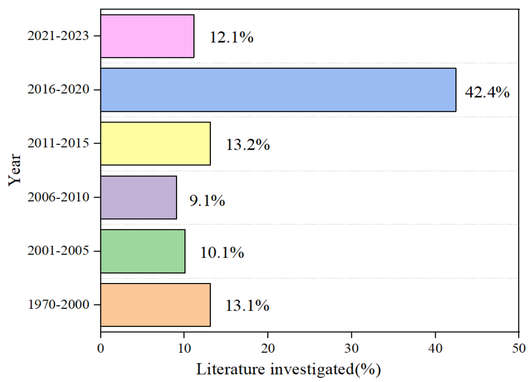
  • In this article, about 67.7% of the surveyed literature belongs to 2011–2023, 19.2% belongs to 2001–2010 and 13.1% belongs to the year before 2000. The annual distribution of the literature is shown in Figure 28;
  • To have a comprehensive understanding of the current research on multiphase pumps, the types of the investigated literature are summarized in Figure 29, which includes experiment, numerical model development, CFD simulation and analysis and optimization design;
  • Various results of the multiphase pump including performance, bubble distribution, vorticity, phase interaction and pressure fluctuation have been obtained. However, there is no single review article that discusses a comprehensive research overview of the gas–liquid multiphase pump.
Experimental observation and CFD simulation are two means to obtain the gas–liquid flow characteristics of the pump. In the experiment, high-speed photography technology is widely applied. The distribution and movement laws of the gas–liquid phases can be obtained by post-processing the flow field images. However, due to the limitations in obtaining comprehensive gas–liquid flow information using experimental technology, CFD simulation has been becoming more popular in the past decade. The information on gas–liquid phase interaction, pressure fluctuation and gas void fraction distribution is easily obtained using CFD methods. The improvement of the CFD prediction ability for the multiphase pump, especially at high IGVF conditions, is one of the major tasks.
Although the existing optimization design technology with the combination of CFD methods can improve the performance of multiphase pumps to a certain extent, the efficiency and head of such pumps have not reached a satisfactory level so far. The direct control strategy of gas—liquid flow is the development direction to improve the performance and operation stability of the multiphase pump.

9. Conclusions

Experimental observation is an important means to obtain the flow pattern in the gas–liquid multiphase pump. The flow patterns could be divided into isolated bubble flow, bubble flow, gas pocket flow, separated gas flow, etc. Due to the high-speed rotation of the impeller, the bubble in the pump will merge and split. Moreover, the aggregation degree of the bubbles increases with the increase in IGVFs.
The turbulence model and multiphase flow model determine the prediction accuracy of the gas–liquid flow in pumps, but they have not yet been unified. The two-equation turbulence model and two-fluid model are used as the numerical model of multiphase flow. The research focus on multiphase pumps is to develop superior numerical models for high IGVFs, including the phase interaction model and bubble balance model.
CFD simulation has become a popular and efficient means to investigate the energy performance and flow characteristics of multiphase pumps. The energy performance such as the efficiency and head of the pump, as well as the complex gas–liquid flow characteristics such as gas distribution, vortex, pressure fluctuation and phase interaction, could be obtained conveniently using CFD methods. Direct and indirect flow control strategies have been applied to improve the comprehensive performance of multiphase pumps, but the effect is still unsatisfactory so far.

Author Contributions

Conceptualization, H.L. and W.Z.; investigation, L.H. and W.Z.; writing—original draft preparation, W.Z.; writing—review and editing, H.L., L.H. and W.Z.; supervision, B.Z. and F.W.; project administration, B.Z., F.W. and W.Z.; funding acquisition, W.Z. All authors have read and agreed to the published version of the manuscript.

Funding

This research was funded by the National Natural Science Foundation of China, grant number 52279092, 52109107; Open Research Fund Program of State Key Laboratory of Hydroscience and Engineering, grant number sklhse-2022-E-03; and the Beijing Municipal Natural Science Foundation, grant number 3212021.

Data Availability Statement

Not applicable.

Conflicts of Interest

The authors declare no conflict of interest.

References

  1. Dale, S. BP Statistical Review of World Energy; BP Plc: London, UK, 2021. [Google Scholar]
  2. Verde, W.M.; Biazussi, J.; Porcel, C.E.; Estevam, V.; Tavares, A.; Neto, S.J.A.; Rocha, P.S.D.M.; Bannwart, A.C. Experimental investigation of pressure drop in failed Electrical Submersible Pump (ESP) under liquid single-phase and gas-liquid two-phase flow. In Proceedings of the 17th Brazilian Congress of Thermal Sciences and Engineering, Águas de Lindóia, Brazil, 25–28 November 2018. [Google Scholar]
  3. Liu, M.; Tan, L.; Cao, S. Method of dynamic mode decomposition and reconstruction with application to a three-stage multiphase pump. Energy 2020, 208, 118343. [Google Scholar] [CrossRef]
  4. Suh, J.-W.; Kim, J.-W.; Choi, Y.-S.; Joo, W.-G.; Lee, K.-Y. Development of numerical Eulerian-Eulerian models for simulating multiphase pumps. J. Pet. Sci. Eng. 2018, 162, 588–601. [Google Scholar] [CrossRef]
  5. Falcimaigne, J.; Brac, J.; Charron, Y.; Pagnier, P.; Vilagines, R. Multiphase pumping: Achievements and perspectives. Oil Gas Sci. Technol. 2002, 57, 99–107. [Google Scholar] [CrossRef]
  6. Shi, Y.; Zhu, H.; Zhang, J.; Zhang, J.; Zhao, J. Experiment and numerical study of a new generation three-stage multiphase pump. J. Pet. Sci. Eng. 2018, 169, 471–484. [Google Scholar] [CrossRef]
  7. Yang, X.; Hu, C.; Hu, Y.; Qu, Z. Theoretical and experimental study of a synchronal rotary multiphase pump at very high inlet gas volume fractions. Appl. Therm. Eng. 2017, 110, 710–719. [Google Scholar] [CrossRef]
  8. Liu, P.; Patil, A.; Morrison, G. Multiphase Flow Performance Prediction Model for Twin-Screw Pump. J. Fluids Eng. 2018, 140, 031103. [Google Scholar] [CrossRef]
  9. Räbiger, K.; Maksoud, T.; Ward, J.; Hausmann, G. Theoretical and experimental analysis of a multiphase screw pump, handling gas–liquid mixtures with very high gas volume fractions. Exp. Therm. Fluid Sci. 2008, 32, 1694–1701. [Google Scholar] [CrossRef]
  10. Feng, C.; Yueyuan, P.; Ziwen, X.; Pengcheng, S. Thermodynamic performance simulation of a twin-screw multiphase pump. Proc. Inst. Mech. Eng. Part E J. Process Mech. Eng. 2001, 215, 157–163. [Google Scholar] [CrossRef]
  11. Cao, S.; Peng, G.; Yu, Z. Hydrodynamic design of rotodynamic pump impeller for multiphase pumping by combined ap-proach of inverse design and CFD analysis. J. Fluids Eng. 2005, 127, 330–338. [Google Scholar] [CrossRef]
  12. Li, Y.; Yu, Z.; Zhang, W.; Yang, J.; Ye, Q. Analysis of bubble distribution in a multiphase rotodynamic pump. Eng. Appl. Comput. Fluid Mech. 2019, 13, 551–559. [Google Scholar] [CrossRef]
  13. Suh, J.-W.; Kim, J.-H.; Choi, Y.-S.; Joo, W.-G.; Lee, K.-Y. A study on numerical optimization and performance verification of multiphase pump for offshore plant. Proc. Inst. Mech. Eng. Part A J. Power Energy 2017, 231, 382–397. [Google Scholar] [CrossRef]
  14. Shi, J.; Tao, S.; Shi, G.; Song, W. Effect of Gas Volume Fraction on the Energy Loss Characteristics of Multiphase Pumps at Each Cavitation Stage. Water 2021, 13, 2293. [Google Scholar] [CrossRef]
  15. Dupoiron, M. The Effect of Gas on Multi-Stage Mixed-Flow Centrifugal Pumps. Ph.D. Thesis, University of Cambridge, Cambridge, UK, 2017. [Google Scholar]
  16. Sato, S.; Furukawa, A.; Takamatsu, Y. Air-water two-phase flow performance of centrifugal pump impellers with various blade angles. JSME Int. J. Ser. B 1996, 39, 223–229. [Google Scholar] [CrossRef]
  17. Zhang, J.; Cai, S.; Li, Y.; Zhu, H.; Zhang, Y. Visualization study of gas–liquid two-phase flow patterns inside a three-stage rotodynamic multi-phase pump. Exp. Therm. Fluid Sci. 2016, 70, 125–138. [Google Scholar] [CrossRef]
  18. Barrios, L.; Prado, M.G. Experimental visualization of two-phase flow inside an electrical submersible pump stage. J. Energy Resour. Technol. 2011, 133, 042901. [Google Scholar] [CrossRef]
  19. Neumann, M.; Schäfer, T.; Bieberle, A.; Hampel, U. An Experimental Study on the Gas Entrainment in Horizontally and Vertically Installed Centrifugal Pumps. J. Fluids Eng. 2016, 138, 091301. [Google Scholar] [CrossRef]
  20. Verde, W.M.; Biazussi, J.L.; Sassim, N.A.; Bannwart, A.C. Experimental study of gas-liquid two-phase flow patterns within centrifugal pumps impellers. Exp. Therm. Fluid Sci. 2017, 85, 37–51. [Google Scholar] [CrossRef]
  21. He, D.; Li, R.; Zhang, Z.; Sun, S.; Guo, P. Gas–Liquid Two-Phase Flow Pattern Identification of a Centrifugal Pump Based on SMOTE and Artificial Neural Network. Micromachines 2021, 13, 2. [Google Scholar] [CrossRef] [PubMed]
  22. Qiaorui, S.; Ali, A.; Biaobiao, W.; Wang, P.; Bois, G.; Jianping, Y.; Kubar, A.A. Numerical study on gas-liquid two phase flow characteristic of multistage electrical sub-mersible pump by using a novel multiple-size group (MUSIG) model. Phys. Fluids 2022, 34, 1–21. [Google Scholar] [CrossRef]
  23. Liu, M.; Tan, L.; Xu, Y.; Cao, S. Optimization design method of multi-stage multiphase pump based on Oseen vortex. J. Pet. Sci. Eng. 2020, 184, 106532. [Google Scholar] [CrossRef]
  24. Parikh, T.; Mansour, M.; Thévenin, D. Investigations on the effect of tip clearance gap and inducer on the transport of air-water two-phase flow by centrifugal pumps. Chem. Eng. Sci. 2020, 218, 115554. [Google Scholar] [CrossRef]
  25. Zhu, J.J.; Zhang, H.Q. Numerical study on Electrical-Submersible-Pump two-phase performance and bubble-size Modeling. SPE Prod. Oper. 2017, 32, 267–278. [Google Scholar] [CrossRef]
  26. Yu, Z.; Zhu, B.; Cao, S.; Liu, Y. Effect of Virtual Mass Force on the Mixed Transport Process in a Multiphase Rotodynamic Pump. Adv. Mech. Eng. 2014, 6, 958352. [Google Scholar] [CrossRef]
  27. Yu, Z.; Zhu, B.; Cao, S. Interphase force analysis for air-water bubbly flow in a multiphase rotodynamic pump. Eng. Comput. 2015, 32, 2166–2180. [Google Scholar] [CrossRef]
  28. Liu, M.; Cao, S.; Cao, S.L. Numerical analysis for interphase forces of gas-liquid flow in a multiphase pump. Eng. Com-Putations 2018, 35, 2386–2402. [Google Scholar] [CrossRef]
  29. Ricardo, D.M.M.; Jiménez, G.E.C.; Ferreira, J.V.; Meirelles, P.S. Multiphase gas-flow model of an electrical submersible pump. Oil Gas Sci. Technol.-Rev. D IFP Energ. Nouv. 2018, 73, 29. [Google Scholar] [CrossRef]
  30. Taguchi, G. Design of Experiment; Maruzen: Tokyo, Japan, 1976. [Google Scholar]
  31. Bonaiuti, D.; Zangeneh, M. On the Coupling of Inverse Design and Optimization Techniques for the Multiobjective, Multipoint Design of Turbomachinery Blades. J. Turbomach. 2009, 131, 021014. [Google Scholar] [CrossRef]
  32. Suh, J.-W.; Choi, Y.-S.; Kim, J.-H.; Joo, W.-G.; Lee, K.-Y. Multi-Objective Optimization of the Hydrodynamic Performance of the Second Stage of a Multi-Phase Pump. Energies 2017, 10, 1334. [Google Scholar] [CrossRef]
  33. Deb, K.; Pratap, A.; Agarwal, S.; Meyarivan, T. A fast and elitist multiobjective genetic algorithm: NSGA-II. IEEE Trans. Evol. Comput. 2002, 6, 182–197. [Google Scholar] [CrossRef]
  34. Zhang, W.; Zhu, B.; Wang, Z.; Wang, F. Optimization design for an impeller of the multiphase rotodynamic pump handling gas-liquid two-phase flow. Proc. Inst. Mech. Eng. Part A J. Power Energy 2022, 236, 1544–1557. [Google Scholar] [CrossRef]
  35. Ping, L.G. Research and development in the oil gas mixture pump technology at home and abroad. J. East China Shipbuild. Inst. 2000, 14, 83–87. (In Chinese) [Google Scholar] [CrossRef]
  36. Paladino, E.E.; de Cerqueira, R.F.; Weise, J.; Lavoratti, T.C.; Caetano, E.F. Theoretical and experimental analysis of multiphase twin-screw pumps op-erating in serial arrangement. J. Pet. Sci. Eng. 2022, 216, 1–20. [Google Scholar] [CrossRef]
  37. Qian, T.; Zhang, Y. Screw optimization for performance enhancement of a twin-screw pump. Curr. Res. Protein Chem. 1990, 228, 159–166. [Google Scholar]
  38. Zhang, W.W.; Zhu, B.S.; Yu, Z.Y. Numerical study on pressure fluctuation in a multiphase rotodynamic pump with different inlet gas void fractions. In IOP Conference Series: Earth and Environmental Science; IOP Publishing: Bristol, UK, 2019; Volume 405. [Google Scholar] [CrossRef]
  39. Xu, Y.; Cao, S.; Sano, T.; Wakai, T.; Reclari, M. Experimental Investigation on Transient Pressure Characteristics in a Helico-Axial Multiphase Pump. Energies 2019, 12, 461. [Google Scholar] [CrossRef]
  40. Zhao, L.; Chang, Z.; Zhang, Z.; Huang, R.; He, D. Visualization of gas-liquid flow pattern in a centrifugal pump impeller and its influence on the pump performance. Meas. Sens. 2021, 13, 100033. [Google Scholar] [CrossRef]
  41. Bratu, C. Two-phase pump transient behaviour. Soc. Pet. Eng. 1995, 30660, 247–261. [Google Scholar]
  42. Barrios, L.; Prado, M.G. Modeling two-phase flow inside an electrical submersible pump stage. J. Energy Resour. Technol. 2011, 133, 042902. [Google Scholar] [CrossRef]
  43. Samaras, V.; Margaris, D. Two-phase flow regime maps for air-lift pump vertical upward gas–liquid flow. Int. J. Multiph. Flow 2005, 31, 757–766. [Google Scholar] [CrossRef]
  44. Julia, J.E.; Hibiki, T. Flow regime transition criteria for two-phase flow in a vertical annulus. Int. J. Heat Fluid Flow 2011, 32, 993–1004. [Google Scholar] [CrossRef]
  45. Simonnet, M.; Gentric, C.; Olmos, E.; Midoux, N. CFD simulation of the flow field in a bubble column reactor: Importance of the drag force formulation to describe regime transitions. Chem. Eng. Process. Process. Intensif. 2008, 47, 1726–1737. [Google Scholar] [CrossRef]
  46. Truman, C.R. Discussion: “A theoretical study on air bubble motion in a centrifugal pump impeller” (Minemura, Kiyoshi, and Murakami, Mitsukiyo, 1980, ASME J. Fluids Eng., 102, pp. 446–453). J. Fluids Eng. 1980, 102, 454–455. [Google Scholar] [CrossRef]
  47. Murakami, M.; Minemura, K. Effects of entrained air on the performance of centrifugal pumps: 2nd Report, Effects of number of blades. Bull. JSME 1974, 17, 1286–1295. [Google Scholar] [CrossRef]
  48. Cubas, J.M.; Stel, H.; Ofuchi, E.M.; Neto, M.A.M.; Morales, R.E. Visualization of two-phase gas-liquid flow in a radial centrifugal pump with a vaned diffuser. J. Pet. Sci. Eng. 2020, 187, 106848. [Google Scholar] [CrossRef]
  49. Qian, H.; Mou, J.; Wu, D.; Ren, Y.; Zheng, S.; Zhu, Z. Experimental investigation on the gas-liquid flow patterns in a centrifugal pump during self-priming process. AIP Adv. 2020, 10, 015136. [Google Scholar] [CrossRef]
  50. Zhang, J.; Cai, S.; Zhu, H.; Zhang, Y. Experimental investigation of the flow at the entrance of a rotodynamic multiphase pump by visualization. J. Pet. Sci. Eng. 2015, 126, 254–261. [Google Scholar] [CrossRef]
  51. Zhang, W.; Zhu, B.; Yu, Z. Characteristics of bubble motion and distribution in a multiphase rotodynamic pump. J. Pet. Sci. Eng. 2020, 193, 107435. [Google Scholar] [CrossRef]
  52. Franke, M. Aspects of Numerical Simulation of Turbomachinery Flows. 2009. Available online: https://elib.dlr.de/62007/ (accessed on 15 August 2023).
  53. Huang, S.; Su, X.; Guo, J.; Yue, L. Unsteady numerical simulation for gas-liquid two-phase flow in self-priming process of cen-trifugal pump. Energy Convers. Manag. 2014, 85, 694–700. [Google Scholar] [CrossRef]
  54. Li, C.; Luo, X.; Feng, J.; Zhu, G.; Xue, Y. Effects of Gas-Volume Fractions on the External Characteristics and Pressure Fluctuation of a Multistage Mixed-Transport Pump. Appl. Sci. 2020, 10, 582. [Google Scholar] [CrossRef]
  55. Caridad, J.; Asuaje, M.; Kenyery, F.; Tremante, A.; Aguillón, O. Characterization of a centrifugal pump impeller under two-phase flow conditions. J. Pet. Sci. Eng. 2008, 63, 18–22. [Google Scholar] [CrossRef]
  56. Pineda, H.; Biazussi, J.; López, F.; Oliveira, B.; Carvalho, R.D.; Bannwart, A.C.; Ratkovich, N. Phase distribution analysis in an Electrical Submersible Pump (ESP) inlet handling water–air two-phase flow using Computational Fluid Dynamics (CFD). J. Pet. Sci. Eng. 2016, 139, 49–61. [Google Scholar] [CrossRef]
  57. He, D.; Ge, Z.; Bai, B.; Guo, P.; Luo, X. Gas–Liquid Two-Phase Performance of Centrifugal Pump Under Bubble Inflow Based on Computational Fluid Dynamics–Population Balance Model Coupling Model. J. Fluids Eng. 2020, 142, 081402. [Google Scholar] [CrossRef]
  58. Ma, Y.; Chen, Y.; Zhang, S. Numerical study on void fraction wave of reciprocating multiphase pumps with high gas rates based on real gas models. Eng. Appl. Comput. Fluid Mech. 2020, 14, 607–621. [Google Scholar] [CrossRef]
  59. Liu, M.; Tan, L.; Cao, S. Influence of viscosity on energy performance and flow field of a multiphase pump. Renew. Energy 2020, 162, 1151–1160. [Google Scholar] [CrossRef]
  60. Kim, J.H.; Lee, H.C.; Kim, J.H.; Choi, Y.S.; Yoon, J.Y.; Yoo, I.S.; Choi, W.C. Improvement of hydrodynamic performance of a multiphase pump using design of experiment techniques. J. Fluids Eng. 2015, 137, 081301. [Google Scholar] [CrossRef]
  61. Stel, H.; Sirino, T.; Ponce, F.J.; Chiva, S.; Morales, R.E.M. Numerical investigation of the flow in a multistage electric submersible pump. J. Pet. Sci. Eng. 2015, 136, 41–54. [Google Scholar] [CrossRef]
  62. Pervaiz, S.S.; Hasan, A.; Dol, S.S.; Gadala, M.S. Numerical investigation of turbulence production under two-phase flow in a simulation of electrical submersible pump performance. J. Fluids Eng. 2022, 1, 011015. [Google Scholar] [CrossRef]
  63. Shu, Z.K.; Shi, G.T.; Dan, Y.; Wang, B.X.; Tan, X. Enstrophy dissipation of the tip leakage vortex in a multiphase pump. Phys. Fluids 2022, 34, 033310. [Google Scholar] [CrossRef]
  64. Zhang, W.; Hu, L.; Li, H.; Zhu, B.; Wang, F. Numerical analysis of bubble size effect in a gas-liquid two-phase rotodynamic pump by using a bubble coalescence and collapse model. Chem. Eng. Res. Des. 2023, 191, 617–629. [Google Scholar] [CrossRef]
  65. Launder, B.E.; Spalding, D.B. Lectures in Mathematical Model of Turbulence; Academic Press: Cambridge, MA, USA, 1972. [Google Scholar]
  66. Yakhot, V.; Orszag, S.A.; Thangam, S.; Gatski, T.B.; Speziale, C.G. Development of turbulence models for shear flows by a double expansion technique. Phys. Fluids A Fluid Dyn. 1992, 4, 1510–1520. [Google Scholar] [CrossRef]
  67. Menter, F.R. Two-equation eddy-viscosity turbulence models for engineering applications. AIAA J. 1994, 32, 1598–1605. [Google Scholar] [CrossRef]
  68. Barrios, L.J. Visualization and Modeling of Multiphase Performance Inside an Electrical Submersible Pump; The University of Tulsa: Tulsa, OK, USA, 2007. [Google Scholar]
  69. Pessoa, R.; Prado, M. Two-Phase Flow Performance for Electrical Submersible Pump Stages. SPE Prod. Facil. 2003, 18, 13–27. [Google Scholar] [CrossRef]
  70. Wang, Z.; Deng, Y.; Pan, Y.; Jin, Y.; Huang, F. Experimentally investigating the flow characteristics of airlift pumps operating in gas-liquid-solid flow. Exp. Therm. Fluid Sci. 2019, 112, 109988. [Google Scholar] [CrossRef]
  71. Lin, Z.H. Vortex Shedding Characteristics and Engineering Application of Gas-Liquid Two-Phase Flow; Chemical Industry Press: Beijing, China, 2001. (In Chinese) [Google Scholar]
  72. Liu, D.Y. Fluid Dynamics of Two-Phase Systems; Higher Education Press: Beijing, China, 1993. [Google Scholar]
  73. Zhang, J.; Li, Y.; Cai, S.; Zhu, H.; Zhang, Y. Investigation of gas–liquid two-phase flow in a three-stage rotodynamic multiphase pump via numerical simulation and visualization experiment. Adv. Mech. Eng. 2016, 8, 1687814016642669. [Google Scholar] [CrossRef]
  74. Benhmidene, A.; Chaouachi, B.; Bourouis, M.; Gabsi, S. Numerical Prediction of Flow Patterns in Bubble Pumps. J. Fluids Eng. 2011, 133, 1–8. [Google Scholar] [CrossRef]
  75. Ofuchi, E.M.; Stel, H.; Sirino, T.; Vieira, T.S.; Ponce, F.J.; Chiva, S.; Morales, R.E.M. Numerical investigation of the effect of viscosity in a multistage electric submersible pump. Eng. Appl. Comput. Fluid Mech. 2017, 11, 258–272. [Google Scholar] [CrossRef]
  76. Murakami, M.; Minemura, K. Effects of entrained air on the performance of a centrifugal pump: 1st report, performance and flow conditions. Bull. JSME 1974, 17, 1047–1055. [Google Scholar] [CrossRef]
  77. Gamboa, J. Prediction of the Transition in Two-Phase Performance of an Electrical Submersible Pump; The University of Tulsa: Tulsa, OK, USA, 2009. [Google Scholar]
  78. Lane, G.; Schwarz, M.; Evans, G. Numerical modelling of gas–liquid flow in stirred tanks. Chem. Eng. Sci. 2005, 60, 2203–2214. [Google Scholar] [CrossRef]
  79. Zhang, W.; Yu, Z.; Li, Y. Application of a non-uniform bubble model in a multiphase rotodynamic pump. J. Pet. Sci. Eng. 2018, 173, 1316–1322. [Google Scholar] [CrossRef]
  80. Liu, P.; Morrison, G.; Patil, A. Experimental and Analytical Investigation of a Novel Multistage Twin-Screw Pump. J. Energy Resour. Technol. 2019, 141, 1–25. [Google Scholar] [CrossRef]
  81. Zhang, W.; Xie, X.; Zhu, B.; Ma, Z. Analysis of phase interaction and gas holdup in a multistage multiphase rotodynamic pump based on a modified Euler two-fluid model. Renew. Energy 2021, 164, 1496–1507. [Google Scholar] [CrossRef]
  82. Sahand, P.; Sujan, G.; Gerald, M. Two-phase flow characterization in a split vane impeller Electrical Submersible Pump. J. Pet. Sci. Eng. 2017, 148, 82–93. [Google Scholar]
  83. Yan, D.; Kovacevic, A.; Tang, Q.; Rane, S.; Zhang, W. Numerical modelling of twin-screw pumps based on computational fluid dynamics. AR-CHIVE Proc. Inst. Mech. Eng. Part C J. Mech. Eng. Sci. 2016, 231, 1989–1996. [Google Scholar] [CrossRef]
  84. Zhu, J.; Zhu, H.; Zhang, J.; Zhang, H.-Q. A numerical study on flow patterns inside an electrical submersible pump (ESP) and comparison with visualization experiments. J. Pet. Sci. Eng. 2019, 173, 339–350. [Google Scholar] [CrossRef]
  85. Fu, W.-S.; Lai, Y.-C.; Li, C.-G. Estimation of turbulent natural convection in horizontal parallel plates by the Q criterion. Int. Commun. Heat Mass Transf. 2013, 45, 41–46. [Google Scholar] [CrossRef]
  86. Hunt, J.; Wray, A.A.; Moin, P. Eddies, Streams, and Convergence Zones in Turbulent Flows; Center for Turbulence Research: Stanford, CA, USA, 1988. [Google Scholar]
  87. Liu, Y.; Tan, L.; Liu, M.; Hao, Y.; Xu, Y. Influence of prewhirl angle and axial distance on energy performance and pressure fluctuation for a centrifugal pump with inlet guide vanes. Energies 2017, 10, 695. [Google Scholar] [CrossRef]
  88. González, J.; Parrondo, J.; Santolaria, C.; Blanco, E. Steady and Unsteady Radial Forces for a Centrifugal Pump with Impeller to Tongue Gap Variation. J. Fluids Eng. 2006, 128, 454–462. [Google Scholar] [CrossRef]
  89. Majidi, K. Numerical Study of Unsteady Flow in a Centrifugal Pump. J. Turbomach. 2005, 127, 805–814. [Google Scholar] [CrossRef]
  90. Feng, J.; Luo, X.; Guo, P.; Wu, G. Influence of tip clearance on pressure fluctuations in an axial flow pump. J. Mech. Sci. Technol. 2016, 30, 1603–1610. [Google Scholar] [CrossRef]
  91. Xie, C.; Tang, F.; Zhang, R.; Zhou, W.; Zhang, W.; Yang, F. Numerical calculation of axial-flow pump’s pressure fluctuation and model test analysis. Adv. Mech. Eng. 2018, 10, 1687814018769775. [Google Scholar] [CrossRef]
  92. Shuai, Z.-J.; Li, W.-Y.; Zhang, X.-Y.; Jiang, C.-X.; Li, F.-C. Numerical Study on the Characteristics of Pressure Fluctuations in an Axial-Flow Water Pump. Adv. Mech. Eng. 2014, 6, 565061. [Google Scholar] [CrossRef]
  93. Miyabe, M.; Maeda, H.; Umeki, I.; Jittani, Y. Unstable head-flow characteristic generation mechanism of a low specific speed mixed flow pump. J. Therm. Sci. 2006, 15, 115–120. [Google Scholar] [CrossRef]
  94. Zhang, W.; Zhu, B.; Yu, Z.; Yang, C. Numerical study of pressure fluctuation in the whole flow passage of a low specific speed mixed-flow pump. Adv. Mech. Eng. 2017, 9, 1687814017707651. [Google Scholar] [CrossRef]
  95. Xu, Y.; Tan, L.; Liu, Y.; Cao, S. Pressure fluctuation and flow pattern of a mixed-flow pump with different blade tip clearances under cavitation condition. Adv. Mech. Eng. 2017, 9, 1687814017696227. [Google Scholar] [CrossRef]
  96. Shi, G.-T.; Liu, Z.-K.; Xiao, Y.-X.; Tang, X.-L.; Liu, X.-B. Pressure fluctuation characteristics in the pressurization unit of a multiphase pump. J. Hydrodyn. 2021, 33, 1230–1241. [Google Scholar] [CrossRef]
  97. Zhang, W.; Yu, Z.; Li, Y.; Yang, J.; Ye, Q. Numerical analysis of pressure fluctuation in a multiphase rotodynamic pump with air–water two-phase flow. Oil Gas Sci. Technol. Rev. d’IFP Energies Nouv. 2019, 74, 18. [Google Scholar] [CrossRef]
  98. Zhang, J.; Zhu, H.; Yang, C.; Li, Y.; Wei, H. Multi-objective shape optimization of helico-axial multiphase pump impeller based on NSGA-II and ANN. Energy Convers. Manag. 2011, 52, 538–546. [Google Scholar] [CrossRef]
  99. Zhang, W.; Zhu, B.; Zi, D.; Ma, Z.; Wang, F. Transportability improvement of a gas-liquid rotodynamic pump using the two-step mul-ti-objective optimization strategy. Front. Energy Res. 2022, 10, 900182. [Google Scholar] [CrossRef]
Figure 1. Structure of twin-screw pump reprinted with permission from Ref. [9].
Energies 16 06292 g001
Figure 2. Helical axial multiphase pump reprinted with permission from Ref. [38].
Energies 16 06292 g002
Figure 3. Pump performance with different IGVFs reprinted with permission from Ref. [39]: (a) head curves; (b) efficiency curves.
Energies 16 06292 g003
Figure 4. Effect of IGVFs and flow patterns on pump performance with data from Ref. [40].
Energies 16 06292 g004
Figure 5. Flow pattern in the first stage of a multiphase rotodynamic pump (n = 2700 r/min) reprinted with permission from Ref. [17]: (a) isolated bubbles flow (IGVF = 0.8%); (b) bubbly flow (IGVF = 6%); (c) gas pocket flow (IGVF = 26%); (d) segregated gas flow (IGVF = 42%).
Energies 16 06292 g005
Figure 6. Flow patterns in a gas–liquid multiphase pump reprinted with permission from Ref. [48]: (a) bubble flow; (b) agglomerated bubble; (c) gas pocket; (d) annular flow.
Energies 16 06292 g006
Figure 7. Variation of bubble size with different IGVFs and rotation speeds reprinted with permission from Ref. [50].
Energies 16 06292 g007
Figure 8. Distribution of bubble size at n = 1800 r/min reprinted with permission from Ref. [50].
Energies 16 06292 g008
Figure 9. Bubble distribution at different IGVFs reprinted with permission from Ref. [51]: (a) IGVF = 3%; (b) IGVF = 9%; (c) IGVF = 15%; (d) IGVF = 21%.
Energies 16 06292 g009
Figure 10. Schematic of bubbles motion law reprinted with permission from Ref. [51].
Energies 16 06292 g010
Figure 11. Comparison results with different bubble size models reprinted with permission from Refs. [25,68,76,77].
Energies 16 06292 g011
Figure 12. Comparison results between CFD and experiment under different IGVFs reprinted with permission from Ref. [79].
Energies 16 06292 g012
Figure 13. Head performance with different IGVFs reprinted with permission from Ref. [79].
Energies 16 06292 g013
Figure 14. Pressure variation along the flow direction reprinted with permission from Ref. [73].
Energies 16 06292 g014
Figure 15. Gas distribution in the meridian plane of pump (n = 1500 r/min, Q = 7.7 m3/h) reprinted with permission from Ref. [57]: (a) IGVF = 2.21%; (b) IGVF = 3.25%; (c) IGVF = 4.86%.
Energies 16 06292 g015
Figure 16. Pump performance with different IGVFs (n = 3000 r/min, Q = 17.55 m3/h) reprinted with permission from Ref. [57].
Energies 16 06292 g016
Figure 17. GVF and streamlines in the multiphase pump with two unit stages (span = 0.15) reprinted with permission from Ref. [81]: (a) d0 = 0.1 mm; (b) d0 = 0.7 mm.
Energies 16 06292 g017
Figure 18. Pressure contour, streamline and vortex structure in impeller at part-load condition reprinted with permission from Ref. [24]: (a) IGVF = 0%; (b) IGVF = 1%; (c) IGVF = 3%.
Energies 16 06292 g018
Figure 19. Magnitude analysis of interphase forces in the impeller reprinted with permission from Ref. [27].
Energies 16 06292 g019
Figure 20. Magnitude ratio of non-drag to drag (IGVF = 9%) reprinted with permission from Ref. [81]: (a) air–water; (b) air–crude.
Energies 16 06292 g020
Figure 21. Pressure fluctuation at IGVF = 15% reprinted with permission from Ref. [97]: (a) fluctuation in impeller; (b) fluctuation in guide vane.
Energies 16 06292 g021
Figure 22. Optimization results with data from Ref. [13].
Energies 16 06292 g022
Figure 23. Comparison curves of impeller performance reprinted with permission from Ref. [98]: (a) GVF-pressure rise curves; (b) GVF-efficiency curves.
Energies 16 06292 g023
Figure 24. Comparison of GVF distributions reprinted with permission from Ref. [98]: (a) unoptimized pressure side; (b) optimized pressure side; (c) unoptimized suction side; (d) optimized suction side.
Energies 16 06292 g024
Figure 25. Turbulent dissipation in original and optimized impeller reprinted with permission from Ref. [23].
Energies 16 06292 g025
Figure 26. Comparison of flow field in the impeller before and after optimization reprinted with permission from Ref. [99]: (a) original impeller; (b) impeller B-opt1; (c) impeller T-opt1.
Energies 16 06292 g026
Figure 27. Blade loading of the optimized impeller reprinted with permission from Ref. [99].
Energies 16 06292 g027
Figure 28. Annual distribution of the literature.
Energies 16 06292 g028
Figure 29. Types of work investigated.
Energies 16 06292 g029
Disclaimer/Publisher’s Note: The statements, opinions and data contained in all publications are solely those of the individual author(s) and contributor(s) and not of MDPI and/or the editor(s). MDPI and/or the editor(s) disclaim responsibility for any injury to people or property resulting from any ideas, methods, instructions or products referred to in the content.

