1. Introduction
LiFePO
4 (LFP) batteries are widely utilized in battery energy storage stations (BESS) and electric vehicles (EVs), due to their exceptional cycling performance, excellent thermal stability, and environmental friendliness [
1,
2]. And such batteries are becoming more and more popular for their competitive prices and improvements in energy density by cell-to-pack technology [
3]. In battery systems, an accurate estimation of the state-of-charge (SOC) is crucial for optimizing the battery charging and discharging, prolonging battery lifespan, and improving energy-storage efficiency [
4]. At present, the mainstream SOC estimation methods include the open-circuit voltage (OCV) method [
5], ampere-hour integration method [
6], and Kalman filter method based on battery models [
7], etc. However, the OCV-based SOC correction methods are prone to correction deviations due to factors such as temperature and aging of battery [
8]. The SOC estimation methods based on machine learning techniques can adapt to different operating environments, offering higher accuracy and robustness [
9]; but, these methods require a significant amount of training data and computational resources, which limits their practicality in engineering applications [
10]. The parameter-adaptive SOC estimation method based on the combination of battery models and machine learning techniques can overcome the errors caused by battery parameter variations; however, more complex algorithms and hardware are required to realize it [
11,
12].
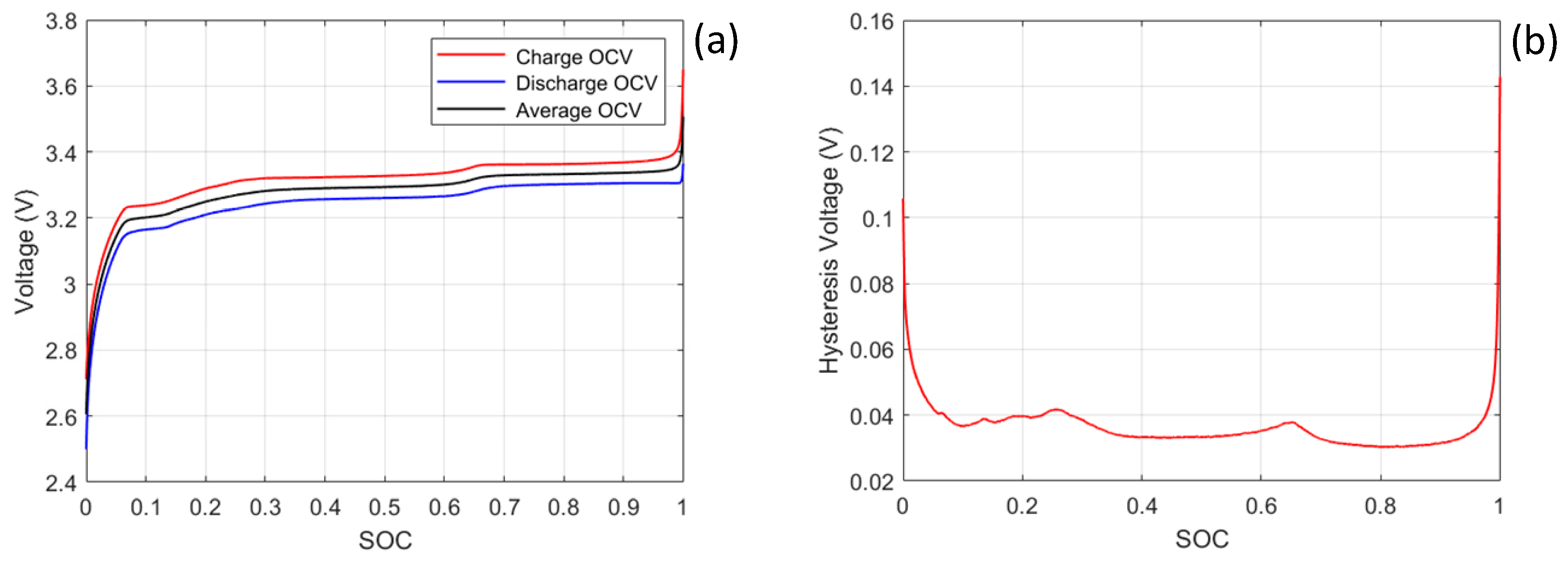
The LFP battery has a wide voltage platform within the 20% to 90% SOC range, and the OCV difference within the voltage platform range is no more than 20 mV. The flatness of the middle section of the SOC–OCV curve, which makes system observability poor, will affect the rate of convergence of iterative algorithms such as the Kalman filter, and also reduces the accuracy of the initial SOC value acquired by the OCV-based correction method [
13,
14]. In addition, LFP batteries have hysteresis characteristics [
15], path dependence [
16], and memory effects [
17]. These unique polarization behaviors limit the accuracy of model-based estimation algorithms in calculating its OCV, further increasing the difficulty of SOC estimation. Therefore, the accuracy of SOC estimation of LFP batteries by existing methods is lower than that of other types of batteries [
18].
Currently, there are mainly two main types of architectures in BESS: centralized topology and multi-branch topology [
19,
20]. In a centralized topology system, it is not possible to manage the charging and discharging of battery clusters, respectively, connected in parallel on the DC bus. When the battery has poor consistency, the inconsistency can lead to increased chances of system shutdown and increased workload for battery consistency maintenance [
19]. In a multi-branch topology battery system as
Figure 1, multiple secondary DC/DC converters are connected in parallel to the DC side of the AC/DC bidirectional converter, where the AC/DC converter can be selected from two-level or three-level topology [
21], and the DC/DC converters can take a multiple-input-single-output topology [
22] or use several modular single-input single-output DC/DC converters in parallel. Compared to the centralized topology, the multi-branch topology has a wider voltage operating range on the DC side, making it easier to implement cluster-based battery charging and discharging management, which enables not only a good compatibility, but also a strong scalability and maintainability [
20,
23,
24]. The battery system with multi-branch topology shows promising prospects for development.
Considering the existing problems of SOC estimation methods for LFP batteries, the present work proposes a full charge and discharge SOC correction method. The proposed method corrects the SOC to 100% when the battery is fully charged and to 0% when it was fully discharged. And the actual usable capacity is corrected by the full-discharged capacity after full charge. This method can correct the cumulative error of the ampere-hour integration method and is not affected by voltage platform and hysteresis characteristics. However, in practical applications, the battery systems may not be able to undergo full charged and full discharge cycling for a long period, due to the operating conditions. Therefore, utilizing the cluster-based control characteristics of the multi-branch topology battery system, the present work proposes an optimization system control strategy to realize the unsynchronized full charge and discharge cluster by cluster, which expands the application range of the full charge and discharge SOC correction method. The system control strategy is simple and easy to implement, which provides a more reliable and efficient battery management scheme for the LFP battery systems, and has a high practical value in engineering.
This paper is organized as follows.
Section 1 analyzes the problems in SOC estimation of LFP batteries.
Section 2 introduces the theory of the full charge and discharge SOC correction method and its control strategy based on the multi-branch battery system.
Section 3 verifies the accuracy of the proposed SOC correction method and the feasibility of the control strategy.
3. SOC Correction Based on Full Charge and Discharge Control Strategy
3.1. SOC Correction Based on Full Charge and Full Discharge
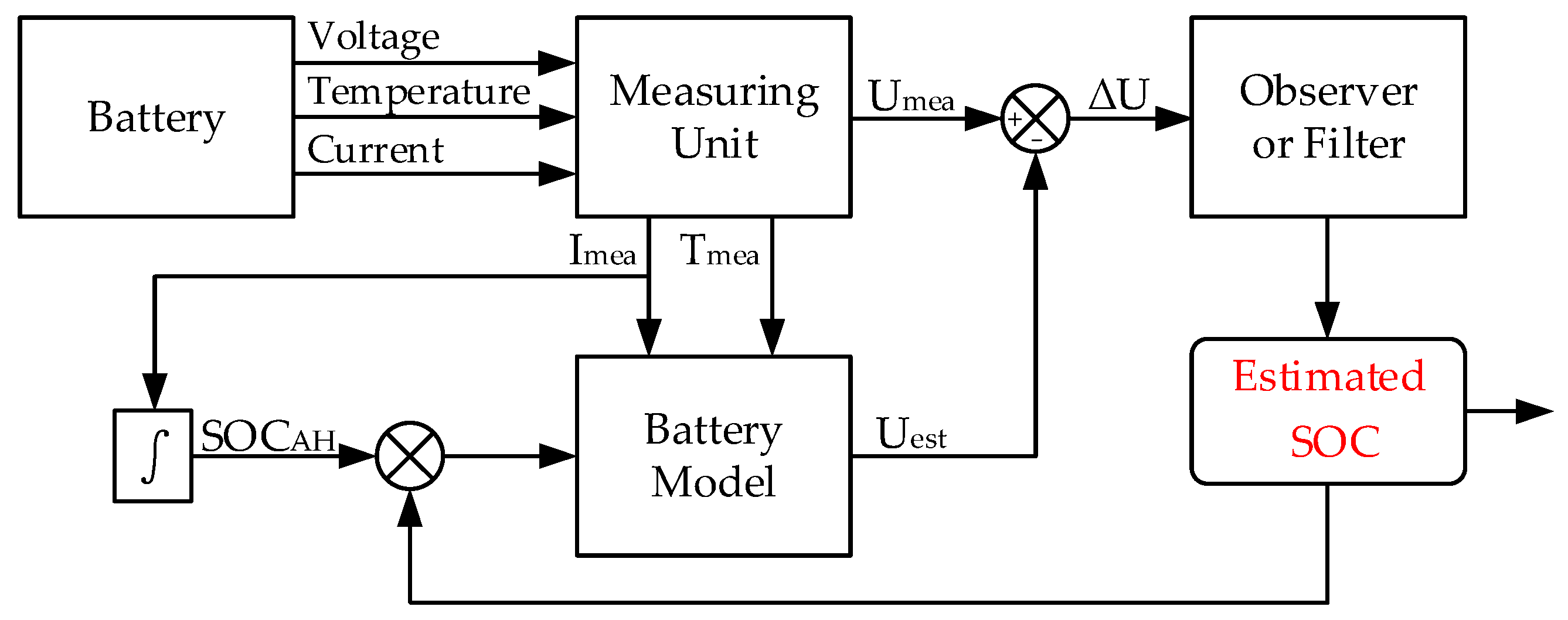
The ampere-hour integration method provides a changed SOC value by integrating the battery current; and combined with the initial SOC value, it provides a current remaining SOC value. This method is computationally simple and widely used in BMS. However, there are two major drawbacks in this method. Firstly, it relies on the accuracy of the initial SOC value. When an error occurs in the initial SOC value, there is also an error in the current SOC value calculated using the ampere-hour integration method. Secondly, when an error occurs in the measurement value, its time accumulated error will be included in the SOC value calculated using this method. The calculation Formula (4) for the ampere hour integration method is given below:
where
is the initial value of SOC,
is the actual usable capacity of the battery,
is the real-time current, and
represents the coulombic efficiency.
The basic principle of the full charge and discharge SOC correction method is to set the SOC value to 100% when the battery reaches its fully charged state, and to 0% when the battery reaches its fully discharged state, for the purpose of dynamically correcting the SOC of the battery system and eliminating accumulated errors. By the full charge and discharge, the actual usable capacity of the battery can also be corrected; that is, the capacity of battery fully discharged after being fully charged, obtained by using the ampere-hour integration method, is used as the actual usable capacity, which further improves the accuracy of the ampere-hour integration method. The principle of the method is quite simple, and it will not be affected by the wide voltage platform and hysteresis characteristics of LFP batteries.
3.2. Control Strategy for Battery Systems in Multi-Branch Topology Structure
In engineering applications, the battery systems may not always undergo full charge and discharge cycling due to the operating conditions. As shown in
Figure 1, the multi-branch topology battery system, the modularization of circuit topology can provide a reduced scale of direct series parallel connection of batteries, refined intensity in battery management and power control, reduced difficulty of battery screening and assembly, and increased means of battery management and control. The parameters of the DC side parallel multi-branch topology can be flexibly adjusted to meet the needs of different power levels and application scenarios. This paper, by utilizing the characteristics of multi-branch topology structure to achieve unsynchronized clustered control, presents a control strategy of reasonably allocating the power of each branch. In this way, the battery clusters could enter a fully charged and fully discharged state cluster by cluster asynchronously, which expands the application range of SOC correction based on full charge and discharge.
The control strategy for achieving full charge and discharge SOC correction based on a multi-branch topology battery system includes the following steps:
Step 1: when SOC correction is required, select a battery cluster and rationally allocate power to prioritize the selected cluster into the fully charged and discharged states, while the remaining battery clusters’ power is flexibly distributed based on the remaining demand power, such as average distribution, weighted distribution according to their respective SOC, etc. When the selected battery cluster is fully charged, correct its SOC as 100%; when it is fully discharged, correct its SOC as 0%.
Step 2: after one round of full charge and discharge is completed for the selected battery cluster, the capacity fully discharged after being fully charged, obtained by using the ampere-hour integration method, is used as the actual usable capacity of the battery to achieve battery capacity correction and further improve the accuracy of the ampere-hour integration method.
Step 3: after the selected battery cluster is fully charged, allocate power to make the SOC of the selected cluster equal to the average SOC of the remaining clusters, and complete the SOC correction for the selected cluster.
Step 4: repeat steps 1–3 to complete the SOC correction of the remaining battery clusters one by one.
Figure 5 is the corresponding control strategy flow chart, where
denotes the total power of the battery system, i.e., the external demand power,
is the power of the selected battery cluster,
is the current of the selected battery cluster,
is the SOC of the selected battery cluster, and
denotes the average SOC of the remaining clusters. The current value is positive during discharging; i.e., the battery system power is negative during charging.
4. Experimental Validation
4.1. Experimental Platform
LFP batteries (LFP48173170E-120Ah, produced by Jiangsu Higee Energy Co., Ltd. in Jiangyin, China) with a rated capacity of 120 Ah were selected as the research object in the present work. The battery system contained two battery packs, and each consisted of six LFP batteries connected in series. The single cell working voltage range used in the experiment was 2.50~3.65 V; so, 21.90 V was set as the cut-off voltage for full charge of the battery pack, and 15.00 V was set as the cut-off voltage for full discharge of the battery pack. Before the experiment began, two battery packs were subjected to three charging and discharging cycles at a current rate of 0.5 C to obtain an average capacity of 125.1 Ah for battery pack 1 and 122.9 Ah for battery pack 2.
The Neware battery pack test system (CE-7002-100V200A, produced by NEWARE Technology Limited in Shenzhen, China) was used to construct a DC side parallel multi-branch topology battery system. It provided two independent battery detection channels, and its internal bidirectional converter circuit conformed to a multi-branch topology structure. With the help of the upper computer software for CE-7002 battery detection (BTS Client 8.0.0.512), it was easy to control and manage the energy of the battery packs. The experimental environment temperature was controlled at 25 °C to reduce the impact of temperature on the experiment. The experimental platform was shown in
Figure 6a;
Figure 6b was the corresponding system structure diagram.
4.2. Experimental Design
The experimental platform constructed in this study provided two battery packs as a theoretical verification platform. The CE-7002 power battery detection system was used to control the simultaneous operation of two battery packs. By setting reasonable steps as
Table 1, comparative experiments were established to verify the accuracy of the full charge and discharge SOC correction method and the feasibility of its control strategy.
Firstly, an alternate full charge and discharge experiment was conducted on battery packs involving the clustered control of multi-branch topology. Under the condition of both battery packs having an initial SOC of 10%, the dynamic distribution of current caused the two battery packs to be fully charged and discharged alternately. The experimental planned to use an alternate operation mode of a single battery pack subject to full charge, full discharge, partial charge, and partial discharge, with a total of five charging and discharging cycles. After each charging or discharging step, a two-hour resting was performed. The work step was set according to
Table 2, and the total output current of the system for the two battery packs during charging and discharging was 120 A. To achieve full charging of the battery, a constant voltage mode was provided during the full charging cycle, with the constant voltage set to 21.90 V and the cut-off current set to 50 A.
The control group experiment was a synchronous partial charge and discharge experiment of the two battery packs distributed with an average power. Under the condition of both battery packs having an initial SOC of 10%, the SOC of the battery pack was controlled between 10% and 90% to conduct constant current charging and discharging, with a total of five charging and discharging cycles. The charging and discharging current of both battery packs was set to 0.5 C (60 A), and the total output current of the system during charging and discharging was 120 A, which was the same as that in the alternate full charge and discharge experiment.
4.3. Control Strategy Results Analysis and Validation
Based on an experiment conducted according to the experimental design scheme mentioned above, two sets data of two battery packs are obtained under alternate full charge/discharge and partial charge/discharge conditions.
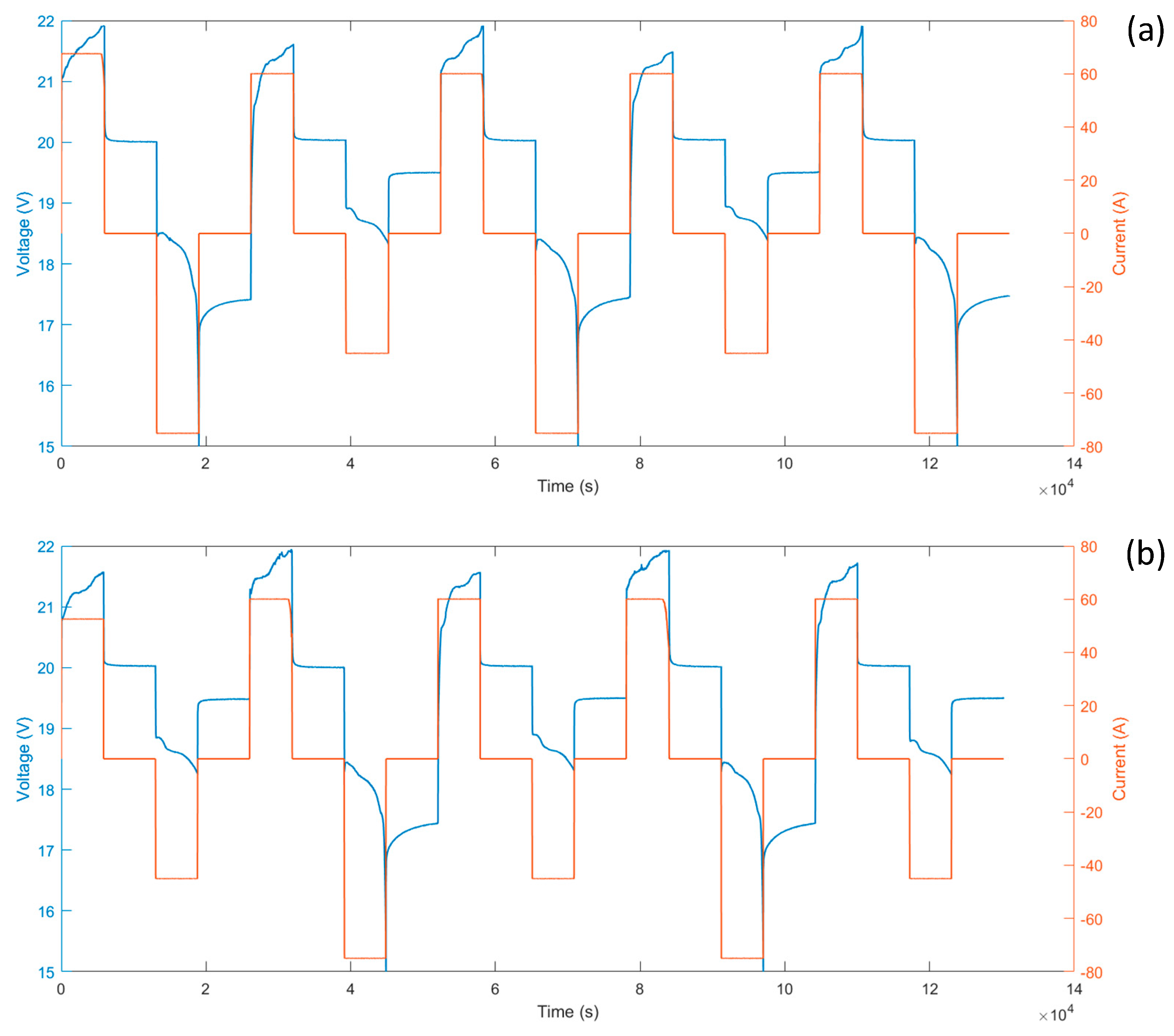
Figure 7a shows the current and voltage curves of battery pack 1 under alternate full charge and discharge conditions. Battery pack 1 is first fully charged and discharged before partial charge and discharge;
Figure 7b shows the curves of battery pack 2, which is first partially charged and discharged before full charge and discharge. From
Figure 7, it can be seen that the constructed battery system can control the power of each of the two channels separately while maintaining consistent total output to achieve alternate full charge and discharge of the battery packs, which verifies the feasibility of the control strategy proposed in this paper.
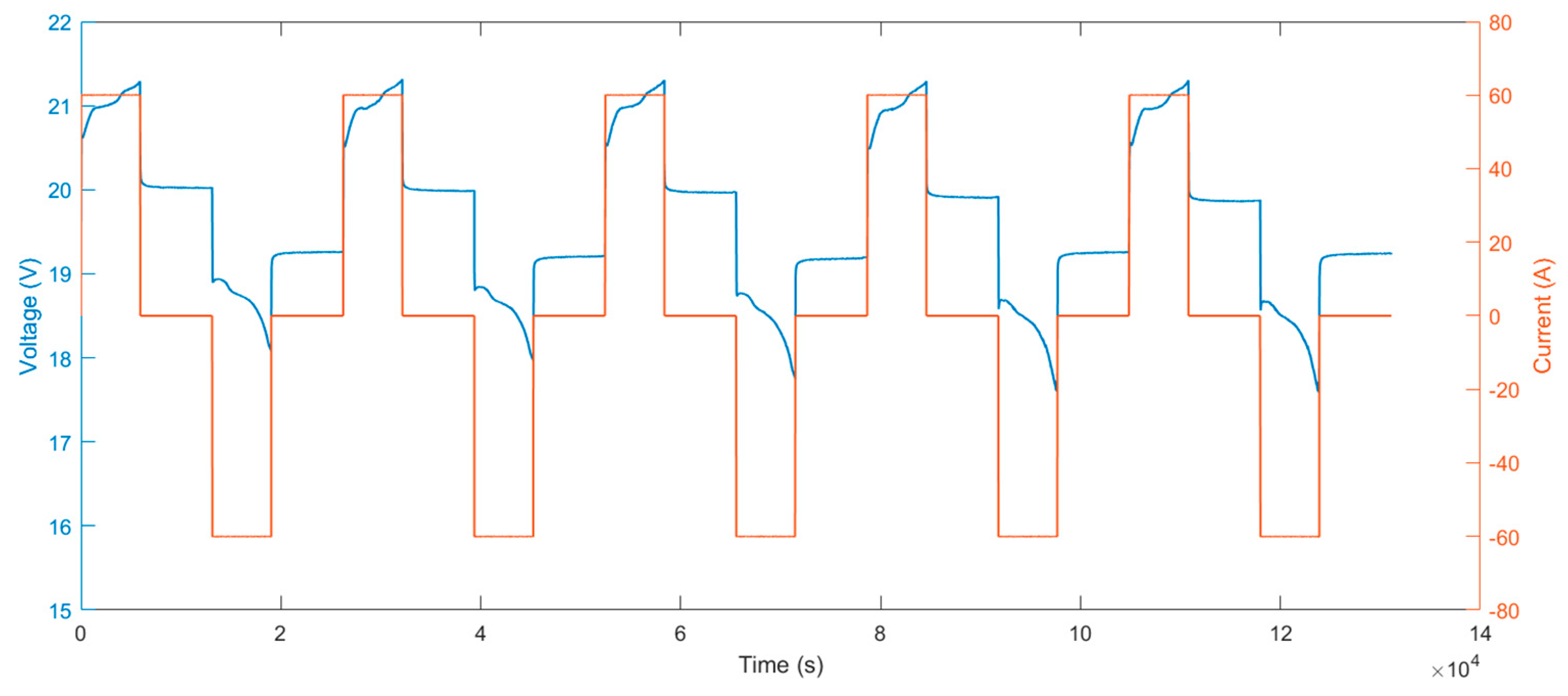
Figure 8 shows the current and voltage curves of battery pack 1 under partial charge and discharge conditions. Seen from the figure, the battery pack is always maintaining at 0.5 C charge and discharge, and the SOC of the battery pack is controlled between 10% and 90%. The curve of battery pack 2 under partial charge and discharge conditions is similar to that in
Figure 7.
4.4. Full Charge and Discharge SOC Correction Results Analysis and Validation
The achieved data can be considered as real value due to the high measurement accuracy of the CE-7002 battery pack detection system in the laboratory. The actual SOC is calculated with the experimental current by the ampere-hour integration method. When doing SOC estimation, white Gaussian noise is added in the experimental current to simulate the measurement error. The SOC estimation value calculated by using the ampere-hour integration method is corrected based on the full charge and discharge SOC correction strategy. Then, we analyzed the feasibility and accuracy of the full charge and full discharge SOC correction method by comparing the estimated and actual SOC.
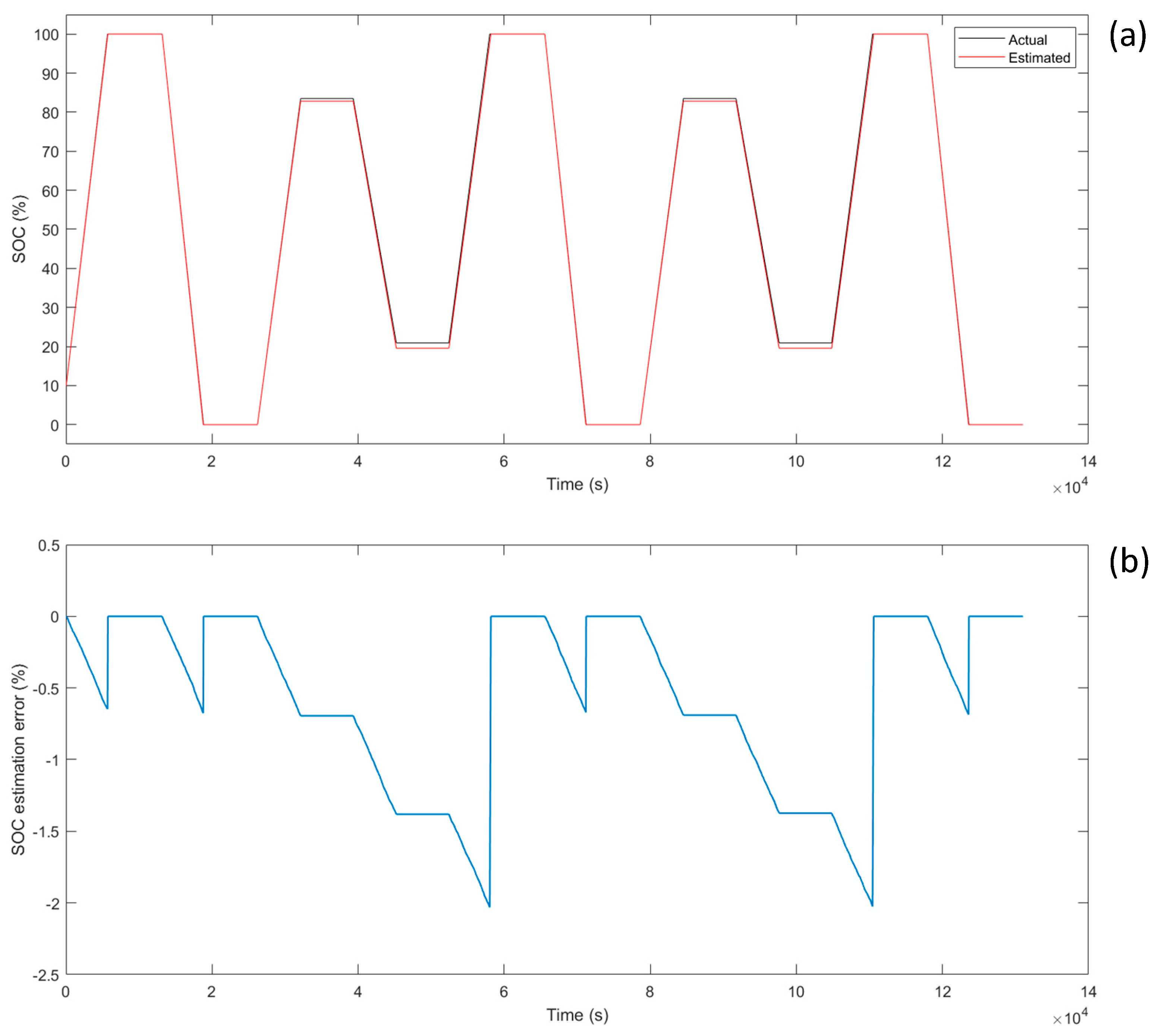
The battery pack data from the alternate full charge and discharge experiment is processed to obtain the information shown in
Figure 9 and
Figure 10, wherein
Figure 9a and
Figure 10a show the comparison between the estimated SOC, which was corrected by the full charge and discharge SOC correction method, and the actual SOC of battery pack 1 and battery pack 2, respectively.
Figure 9b and
Figure 10b show the corresponding SOC estimation errors. From the figures, it can be seen that adding noise increases the SOC estimation error of the battery system over time; and when the full charge and discharge condition is triggered, the SOC estimation error value returns to zero. After five working cycles, the error value remains less than 2.23%.
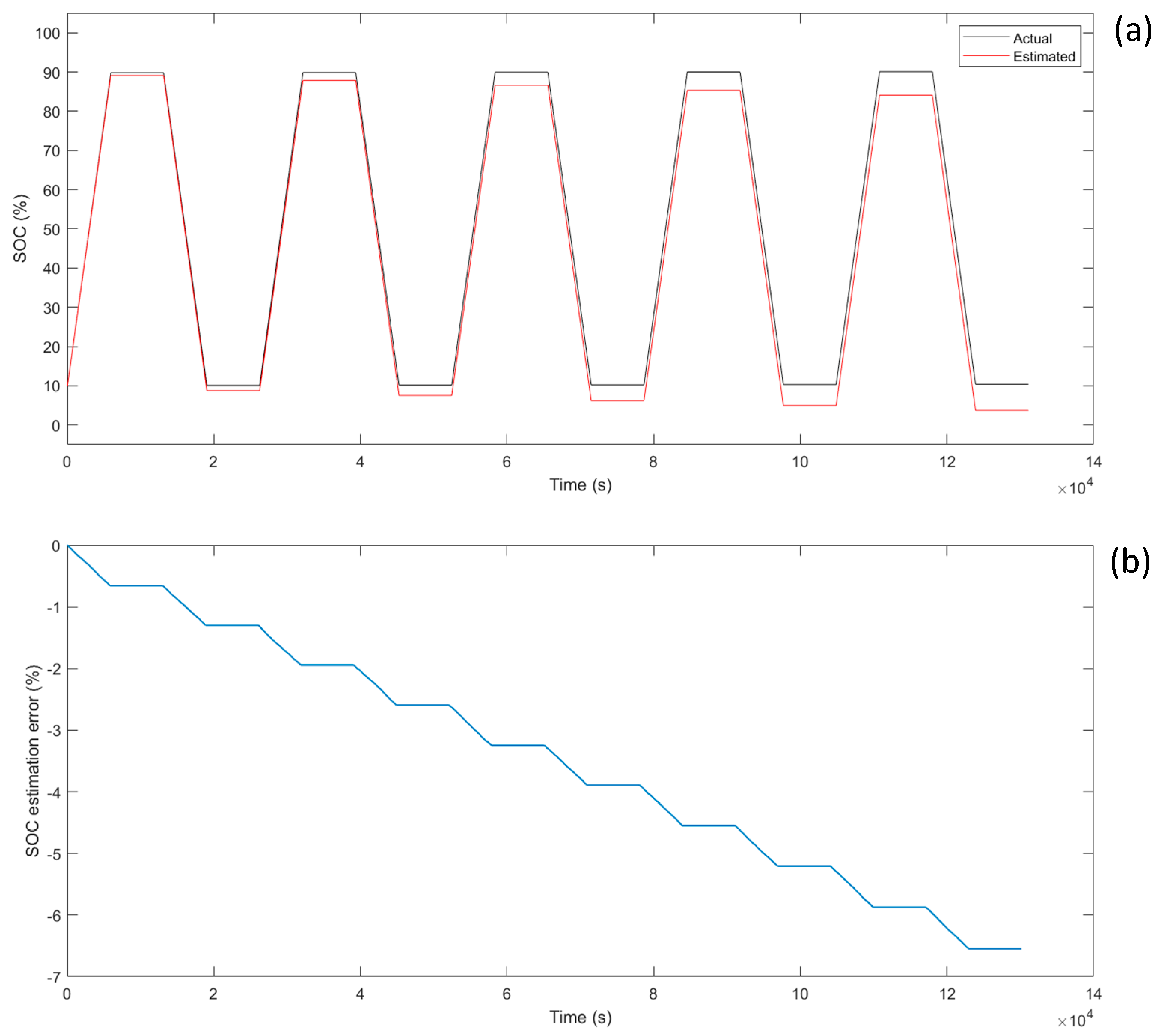
Similarly, the data of battery pack 1 in the partial charge and discharge experiment are processed to obtain the information shown in
Figure 11, wherein
Figure 11a shows the comparison between the estimated SOC without being corrected and the actual SOC of battery pack 1 under the conditions of partial charge and discharge, while
Figure 11b shows the corresponding SOC estimation error. It can be seen that the added noise causes the SOC error value of the system to increase uniformly over time. Moreover, due to the battery pack not reaching the fully charged/discharged state, which means it unable to trigger the correction condition, the estimated error value gradually increases. After five working cycles, the error exceeds 5% and reaches 6.67%. The data of battery pack 2 under this operating condition are basically the same as that of battery pack 1.
Comparing the results from
Figure 8 with those from
Figure 10, it is clear that the full charge and full discharge SOC correction method works well, which effectively reduces the accumulated error of the ampere-hour integration method through dynamic correction. And it verifies the feasibility of the system control strategy, which realizes the unsynchronized full charge and discharge cluster by cluster in the multi-branch topology battery system.
5. Conclusions
In order to improve the SOC estimation accuracy in LFP batteries, the full charge and discharge control strategy was proposed in the multi-branch topology battery system. It can effectively eliminate the cumulative error of the ampere-hour integration method during charging and discharging processes. The validation experimental results indicate the corrected SOC estimation error is no more than 2.23%. The proposed optimized control strategy makes full use of the cluster-based control characteristics of the multi-branch topology battery system. The unsynchronized full charge and discharge is realized by reasonably distributing the power of each parallel battery cluster branch. In this way, the application of the SOC correction method based on full charge and discharge control strategy can be extended. The proposed SOC correction method and the system control strategy are simple in principle and easy to implement, and provide a more reliable and efficient battery management scheme for the LFP battery system, which has a high practical value in engineering.
Future research directions contain four aspects for this work: (1) research work should be conducted to further optimize the power distribution strategy of the battery clusters to adapt to more complex working environments, and then to improve the economic efficiency and reliability of the system; (2) other types of SOC estimation methods, such as the Kalman filter and neural network method, should be combined to improve the accuracy and stability of SOC estimation; (3) more applying scenarios, such as new energy vehicles, smart microgrids, wind and solar energy storage, and cascade utilization, should be tested by the proposed strategy to verify its adaptability and effectiveness in different scenarios; and (4) in practice, fully charging and discharging the battery can accelerate the ageing of the system, so the frequency of SOC correction should be adjusted appropriately considering the state of health.


