1. Introduction
The traditional direct current (DC) transmission system converter components are thyristors, which are semi-controlled devices. The phase change requires the application of additional alternating current (AC) voltage at the receiving end to ensure a large enough short-circuit capacity; otherwise, it is easy for phase change failure to occur or even for the grid to collapse. Moreover, for the converter operation to be equipped with a large number of filters and reactive power compensation devices, the construction costs are very high [
1,
2,
3]. In contrast to traditional DC transmission systems, flexible DC transmission uses a switchable insulated gate bipolar transistor (IGBT) and pulse width modulation (PWM) control devices in the converter, has passive characteristics, can supply power to islands, can achieve four-quadrant power flow, and significantly reduces the number of reactive power compensation devices and filters in scale, which significantly reduces the difficulty and cost of construction [
4,
5,
6,
7,
8].
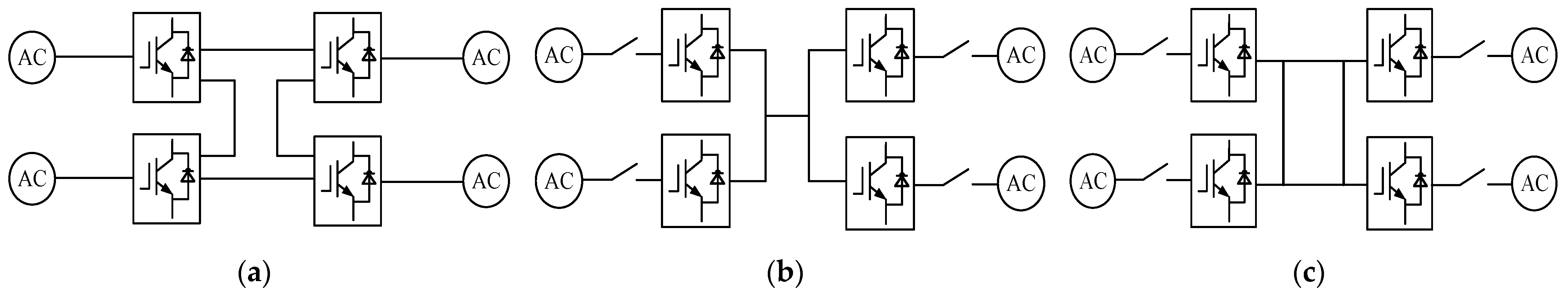
Multi-terminal flexible DC electric power transmission (MTDC) was developed from flexible DC electric power transmission (HVDC). It is usually composed of a converter station, connection transformer, phase reactor, filter, DC line, and DC capacitor and can connect three or more AC systems. The converter station can undertake both rectification and inverter tasks, increasing the reliability and flexibility of the power supply. Currently, the multi-terminal flexible DC transmission system is mainly divided into two types of structures: series-type and parallel-type structures. The series-type structures are relatively simple, but all the converter stations need to be shut down in cases of failure, and the reliability and flexibility of the power supply are poor. The parallel structures are also divided into radial and ring types. This structure makes it easy to expand the power grid; a fault in other places does not affect it, and the power supply flexibility and reliability are significantly enhanced. Taking the four-terminal flexible DC transmission system as an example, the connection methods are shown in
Figure 1. Thanks to the above advantages, multi-terminal flexible DC transmission technology is widely used in offshore wind power delivery, renewable energy grid connection, isolated island power supply, urban power grid expansion, etc. [
9,
10].
In voltage source converter-based multi-terminal flexible DC electric power transmission (VSC-MTDC), it is necessary to ensure that the sum of the active power inputs from each converter station is equal to the sum of the active power outputs and losses from each converter station. If a power imbalance occurs, it will cause changes in the DC-side voltage of the VSC-MTDC system. Therefore, at least one converter station must control the DC-side voltage, which acts as a balancing node in the AC network, while the other converter stations achieve power distribution.
Currently, VSC-MTDC system control methods include master–slave control, DC voltage margin control, and droop control. Master–slave control requires high real-time communication, and the system loses the ability to balance the power among converter stations when there is a communication failure, or the master station is out of operation. Voltage margin control does not require inter-station communication, but as the scale of a VSC-MTDC system expands, the voltage margin becomes difficult to adjust, and it is easy for power oscillation to occur when the system is in stable operation.
Droop control, on the other hand, does not have the above problems. Droop control can achieve coordinated power distribution by measuring the bus voltage and relying on local controllers without relying on inter-conversion communication, and it is, therefore, suitable for applications with a large number of converter stations and frequent power fluctuations. Common droop control methods include droop control based on the P-U characteristic curve and droop control based on the U-I characteristic curve.
However, the droop control strategy also has some problems in the actual operation of a multi-terminal system. For example, the droop controller has a limited ability to regulate the power, while the DC voltage is more sensitive to power changes, and when the emergence of unbalanced power exceeds the adjustable range, it causes the DC voltage to cross the limit, resulting in increased losses in or damage to the power electronics and affecting the safe and stable operation of the system. In order to achieve coordinated control between power and voltage, the traditional droop control strategy using a fixed droop factor has been improved. In [
11], a new adaptive voltage droop control strategy was proposed to address the problem of poor DC voltage control in extreme cases with conventional droop controllers. The strategy considers the local electrical variables of the converter with droop control. Reference [
12] analyzed the frequency domain stability of the MTDC system droop control and solved the droop factor range to satisfy the power balance of the multi-terminal system. Reference [
13] proposes the addition of an upper-level system controller to the conventional droop control to solve the optimal solution for the DC voltage and active power reference values of each converter to improve the operating efficiency and dynamic performance of the system. Reference [
14] proposed an adaptive droop control method based on improved reference power. Without adjusting the droop gain, the local power deviation is used to compensate for the original reference power, which achieves a shift of the DC voltage toward its rated value and reduces the risk of DC voltage overrun. Reference [
15] describes the design of an improved voltage droop controller that maintains the voltage of all converters within their design limits and maximizes the power transfer of the HVDC system.
The main innovation of this paper is the proposal of an improved adaptive droop control method. This method introduces an influence factor to adaptively correct the droop factor by detecting the DC voltage deviation so that the droop factor can be adaptively adjusted according to the power change, thereby enhancing the power regulation capability of the controller.
The paper is organized as follows:
Section 2 investigates the power distribution of a flexible DC transmission system based on voltage droop control.
Section 3 proposes an adaptive droop control method based on power variation.
Section 4 presents the simulation results of the proposed method. The conclusion is written in
Section 5.
2. Analysis of a Four-Terminal DC Transmission System Based on Droop Control
In order to address the power distribution problem among the receiving converter stations, this paper presents the voltage droop control strategy; the control system model block diagram is shown in
Figure 2. The active power is influenced by the d-axis current
, while the reactive power depends on the q-axis current
output from the droop controller. The d-axis and q-axis currents are responsible for controlling the active and reactive power, respectively.
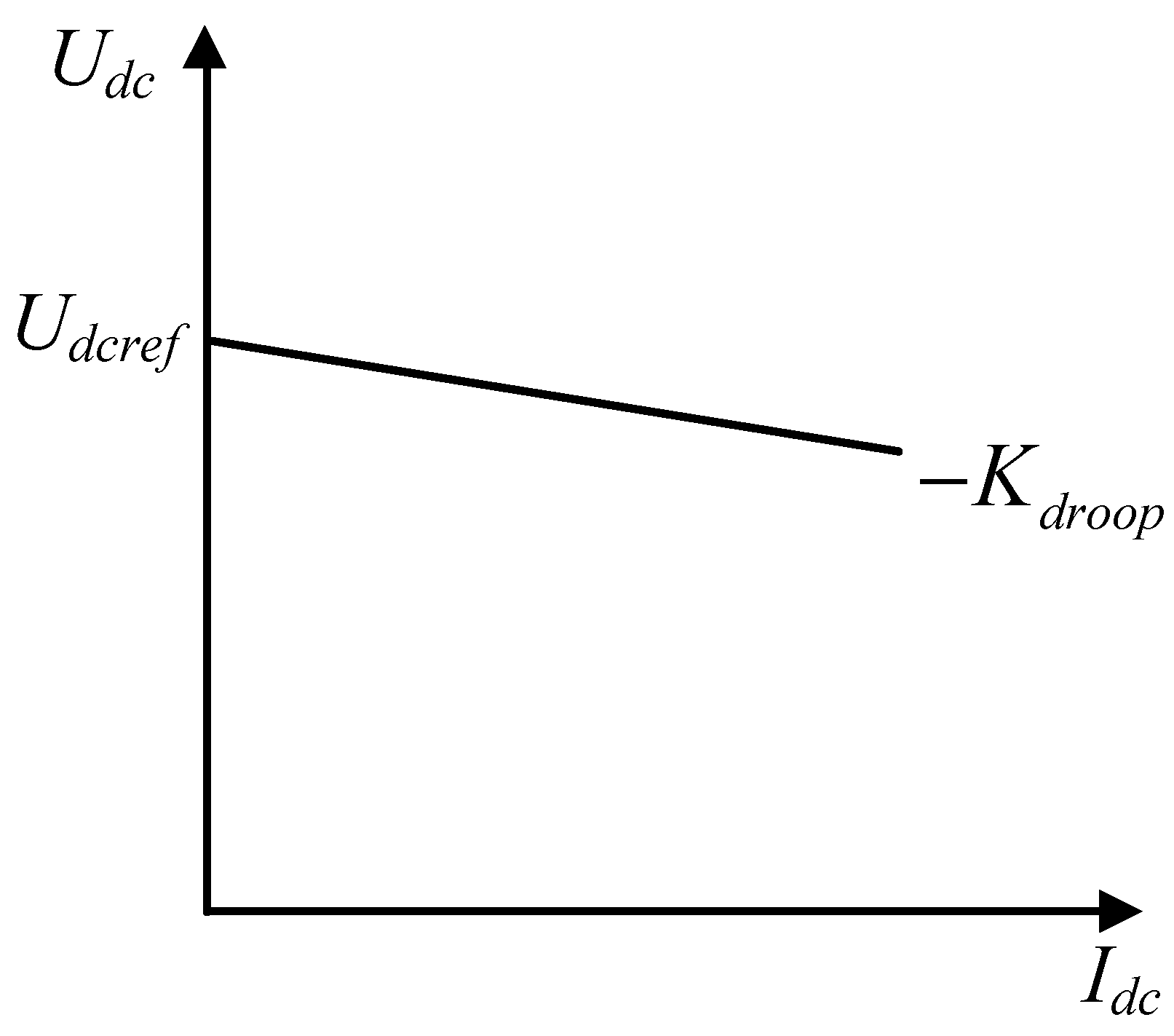
The droop control U-I characteristics are shown in
Figure 3. Under normal operation, the system operates at a specific point on the characteristic curve; however, in the event of a fault or external disturbance, the operating point shifts along the characteristic curve and readjusts to a new steady-state operating point, enabling the system to quickly resume normal operation [
16,
17,
18].
From
Figure 3, the relationship between DC voltage and current is,
where
and
are the actual DC voltage of the converter station and its reference value, respectively,
and
are the actual DC current of the converter station and its reference value, respectively, and
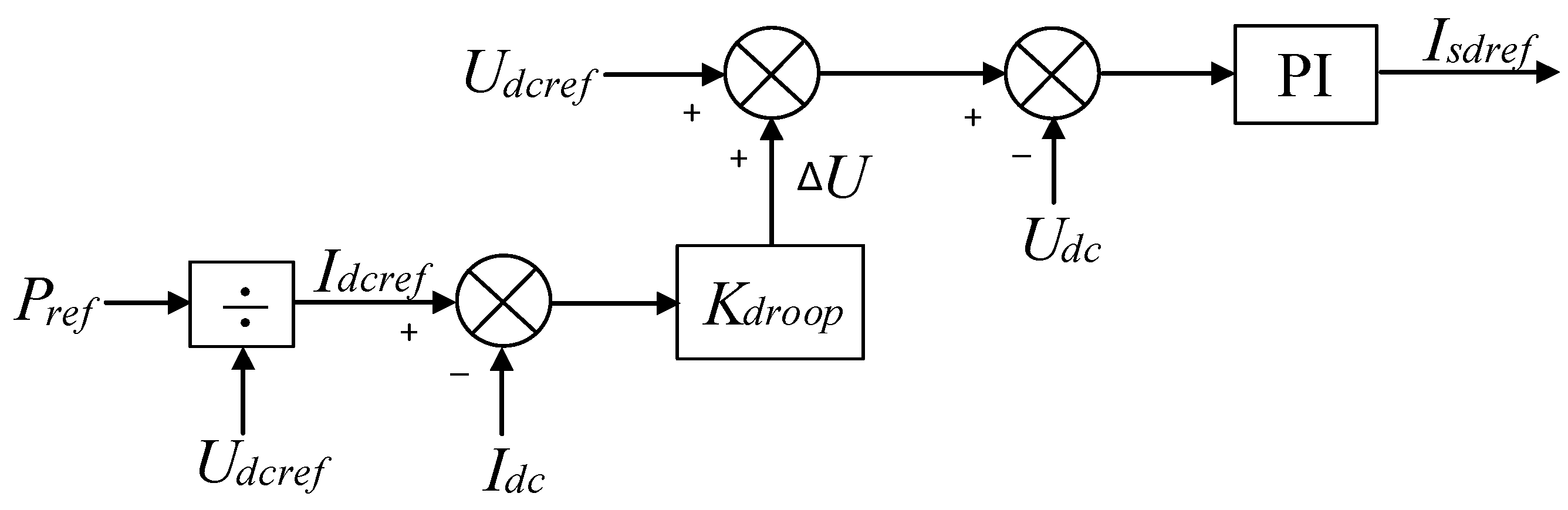
is the droop factor. The voltage droop controller is shown in
Figure 4.
The droop factor can be represented as a virtual resistance . By altering the magnitude of this virtual resistor, the ratio of the distributed power among the individual converter stations can be modified.
Ignoring the voltage drop on the transmission line, the DC side voltage of each converter station remains approximately constant. Active power distribution is achieved by controlling the DC current of each converter station, and the proportion of power distribution can be calculated by adjusting the droop control factor.
The converter stations VSC1 and VSC3 at the sending end, which have constant active power control, can be considered as current sources. The converter stations VSC2 and VSC4 at the receiving end, which have voltage droop control, can be considered as voltage sources [
19,
20].
Figure 5 depicts the equivalent circuit of this four-terminal flexible DC transmission system.
According to Equation (1), the droop control can be understood as connecting a virtual resistor
r in series on the DC side of the converter station. By changing the size of this virtual resistor, the proportion of power distribution between droop stations can be adjusted.
Using the star network transformation and superposition theorem to simplify the equivalent circuit shown in
Figure 5, the currents
and
can be calculated as
and is the DC current on the VSC1 and VSC3 sides at the sending end, and is the DC current on the VSC2 and VSC4 sides at the receiving end, and , , , , , , , and is the resistance on the transmission line, where .
The power distribution ratio of the droop control station is determined by the line resistance and droop factor. To investigate the impact of the droop factor on power distribution, we assume a resistance of 0.1 ohm for each resistance on the line. Formula (4) is derived by simplifying Formula (3), and it provides the values of currents
and
, which are
During the stable operation of the multi-terminal flexible DC transmission system, the DC voltage fluctuation is minimal, and the steady-state operating point of the DC voltage should be roughly near the reference voltage. Therefore, it can be considered that the DC voltage of each converter station port is approximately equal. Based on this assumption, the power distribution of the droop control station has the following relationship:
From the above equation, it can be seen that the power distribution can be altered by adjusting the magnitude of the virtual resistances and This adjustment affects the magnitude of the received power and at the converter station. The droop factors of VSC2 and VSC4 can be modified to achieve this adjustment.
However, droop control also has some disadvantages. One of the challenges is the difficulty in selecting the slope characteristic curve for each converter station. Additionally, the regulation ability of power is limited, and when the converter station reaches the power limit, it will change to fixed active power control and lose the droop characteristic. This can result in a serious voltage increase accident. In order to achieve coordinated control between power and voltage, the traditional droop control strategy using fixed droop factors is usually improved.
3. Adaptive Droop Control Optimization Strategy
In the actual flexible DC transmission scenario, the influence of system expansion or the connection of distributed new energy grids will lead to voltage fluctuations or power imbalance in the converter station; however, when using droop control with fixed factors, there is a conflict between the ability to regulate power balance and maintain voltage stability.
When the droop factor becomes larger, the slope of the U-I characteristic curve becomes larger, the regulation of active power becomes more sensitive, and the ability to maintain DC voltage stability becomes worse. Conversely, when the droop factor decreases, the slope of the U-I characteristic curve also becomes smaller, the ability to regulate DC voltage stability is enhanced, and the ability to regulate active power balance is weakened [
21]. Essentially, the size of the droop factor determines the strength of the power regulation performance of the whole multi-terminal system. When the droop factor is zero, the U-I characteristic curve is similar to constant active power control. When the droop factor is close to infinity, the U-I characteristic curve is similar to fixed DC voltage control.
Figure 6 shows the U-I characteristic curves for constant DC voltage control and constant active power control.
To enhance the controller’s capability to regulate power fluctuations under various working conditions, this study proposes an adaptive droop control method. The method aims to optimize the performance of droop control by leveraging its advantages in different working conditions.
First, the adaptive factor α is introduced on the basis of Equation (1):
where
is the difference between the DC voltage reference value and the actual value, and
is the voltage deviation threshold set according to the system operation. Then, the newly formed adaptive droop control U-I relationship equation is
The droop factor
after adaptive droop control optimization is
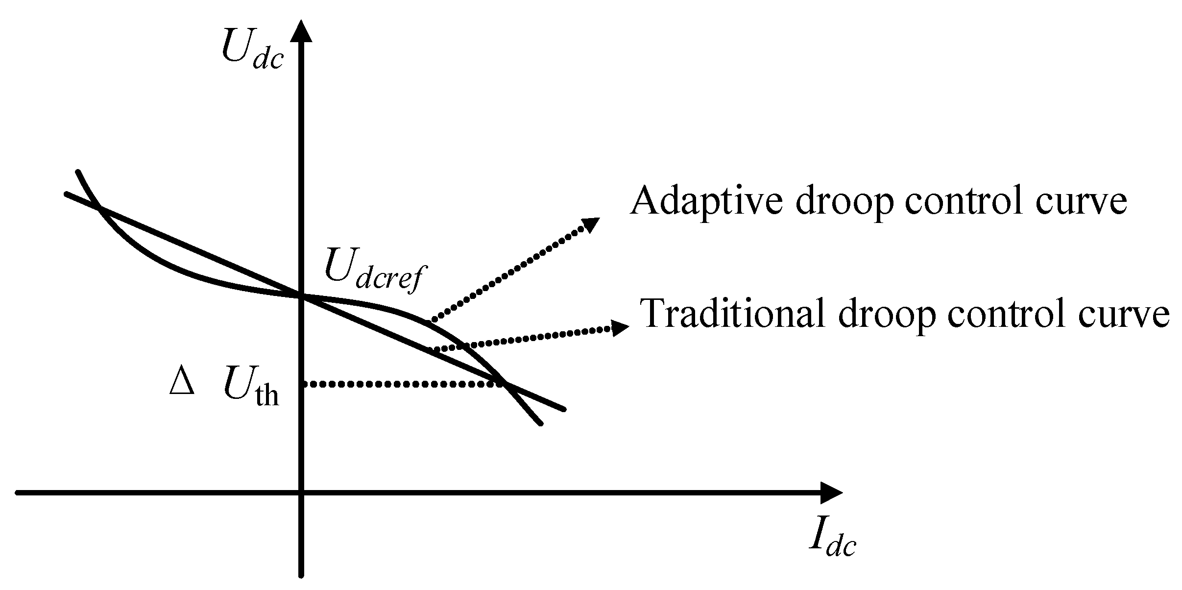
Compared with the fixed factor adaptive droop control U-I relationship (1), it can be found that the improved adaptive droop control DC voltage deviation
is smaller than the fixed factor adaptive droop control DC voltage deviation
. This control method effectively enhances the system’s ability to control the DC voltage. The characteristic curve of the adaptive droop control is depicted in
Figure 7.
The variation of the adaptive droop factor can be summarized by the following equation:
where
is the maximum voltage deviation allowed in the system, usually taken as 5% of
. In order to avoid frequent adjustments to the droop factor caused by DC voltage fluctuations, a voltage deviation threshold
should also be set. This ensures that the droop factor does not need to be changed in the case of small power fluctuations.
The improved droop control optimization scheme involves three scenarios. First, when the power fluctuation is small, in order to prevent the frequent change of droop factor caused by DC voltage fluctuation, the voltage threshold is set using a hysteresis comparator, and when the voltage deviation does not exceed the threshold, the droop factor is kept unchanged and can be adjusted by the original droop controller. Second, when the power fluctuation is large, and the voltage deviation exceeds but does not exceed , the droop factor becomes smaller, and the voltage deviation caused by the power fluctuation is reduced compared with the original droop control; the focus of the controller at this time is to stabilize the DC voltage. Lastly, in high power change scenarios, such as when the converter station is out of operation, if the voltage deviation does not exceed the maximum voltage deviation allowed by the system, the droop factor increases. In this case, the controller focuses on power regulation, while the power absorbed by the converter station becomes smaller compared with the original droop control, thus ensuring a certain power margin.
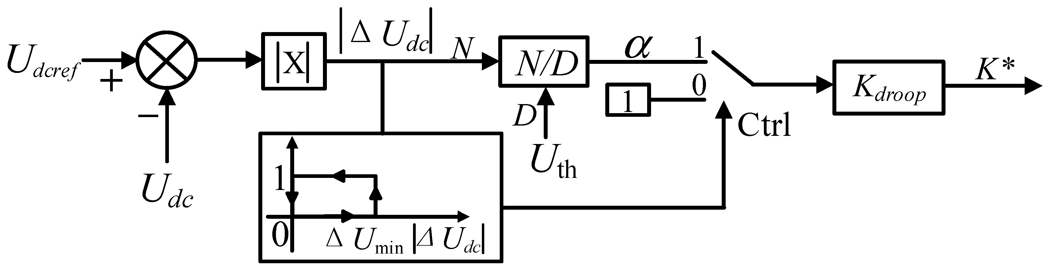
The adaptive droop controller is shown in
Figure 8, and the specific process of operation is as follows: The DC voltage reference value
is subtracted from the actual DC voltage value
, and the DC voltage offset value is generated by taking the absolute value and comparing it with
, which generates the adaptive factor
shown in Equation (6). Based on the different working conditions described in Equation (9), the adjusting tendency of the adaptive factor
is determined to generate the dual-input selector control signal. This control signal is then used to adjust or maintain the droop factor accordingly.
The adaptive droop controller is essentially to analyze and correct the adaptive factor α in different working conditions. It then multiplies this factor with the original droop factor to regenerate the new droop factor.
4. Case Study
The electromagnetic transient simulation model corresponding to
Figure 9 was created in PSCAD. The two sending-end converter stations, VSC1 and VSC3, utilize constant active power control, while the two receiving-end converter stations, VSC2 and VSC4, adopt droop control. By adjusting the droop factor, the received power magnitude can be modified while maintaining the stability of the DC voltage.
The parameters of one converter station are shown in
Table 1.
4.1. Analysis of Power Allocation Examples for Traditional Droop Control
The DC reference voltages of VSC2 and VSC4 receiving converter stations, when using traditional droop control, are set at 500 kV. As shown in
Figure 10, the traditional droop control has a good ability to regulate the DC bus voltage, and the DC voltage of the receiving converter station is stable at 500 kV.
In order to verify the correctness of the derivation of the power distribution relationship when the traditional droop control is used, we conducted verification using the following two cases.
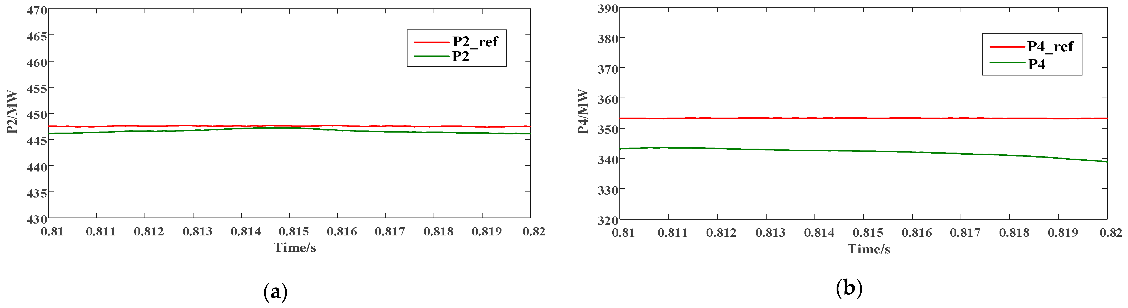
In the first case, the two converter stations, VSC1 and VSC3, at the sending end, were set to output 400 MW of active power, respectively. Droop factors are generally selected based on the capacity of the converter station; the droop factor of VSC2 at the receiving end was set to 0.05, and the droop factor of VSC4 at the receiving end was set to 0.1.
From Equation (5), VSC2 should theoretically receive an active power
of 447 MW, and VSC4 should theoretically receive an active power
of 353 MW, and from
Figure 11, VSC2 actually receives an active power
of about 446 MW, and VSC4 actually receives an active power
of about 343 MW.
In the second case, the output power of the two converter stations at the sending end is kept unchanged, the droop factor of VSC2 at the receiving end is set to 0.05, and the droop factor of VSC4 is set to 0.15. From Equation (5), it is known that VSC2 should theoretically receive an active power
of 484 MW, and VSC4 should theoretically receive an active power
of 316 MW. According to
Figure 12, the actual received active power
of VSC2 is approximately 483 MW, and the actual received active power
of VSC4 is about 306 MW.
The power allocation results of converter stations using traditional droop control with different droop factors are summarized in
Table 2.
The reference value of the received power from the droop control station is the theoretical value in an ideal state without considering the active power consumed by the line resistance. It is precisely because of this part of the loss that the error between the reference value and the actual value is caused, and the line loss cannot be avoided. Based on the power distribution results, the problem aligns with the expected settings.
4.2. Simulation Verification of Adaptive Droop Control
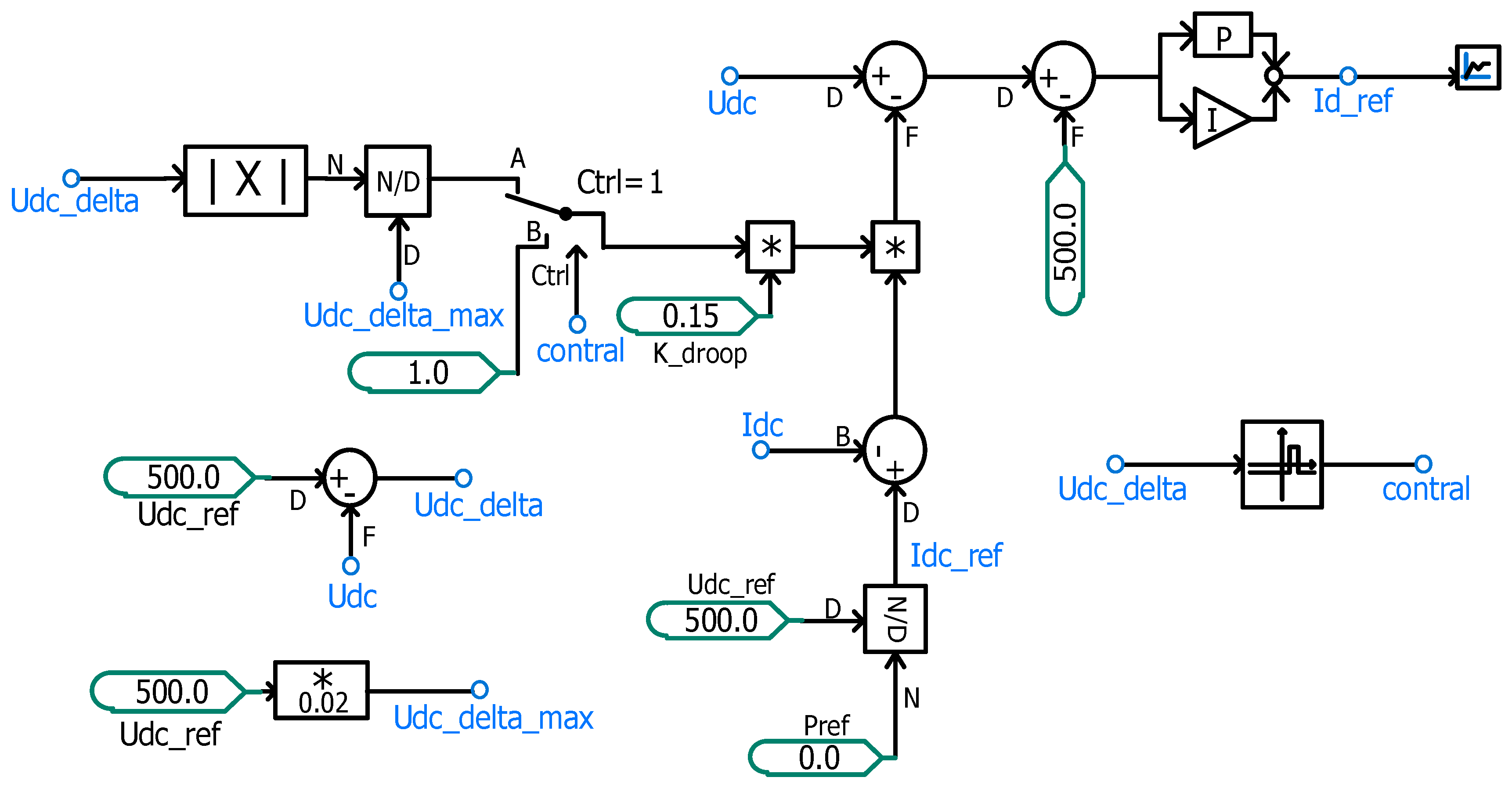
To evaluate the adaptive regulation capability of the proposed improved droop control method, it is necessary to improve the traditional droop controller. The improved adaptive droop controller, shown in
Figure 13, can be easily implemented by incorporating hysteresis loop control and a changeover switch into the original droop controller.
The hysteresis controller threshold is set to 2 kV, and the droop factor is kept constant when the absolute value of voltage deviation ; is set to 10 kV, which is used as the dividing line to design the changeover switch and correct the droop factor, decreasing the droop factor when and increasing it when .
To investigate the steady state and dynamic process of the converter station after adopting adaptive droop control when the transmitted power changes. Firstly, the initial droop factors of the receiving end converter stations VSC2 and VSC4 are set to 0.15. This ensures that both converter stations can receive the same power.
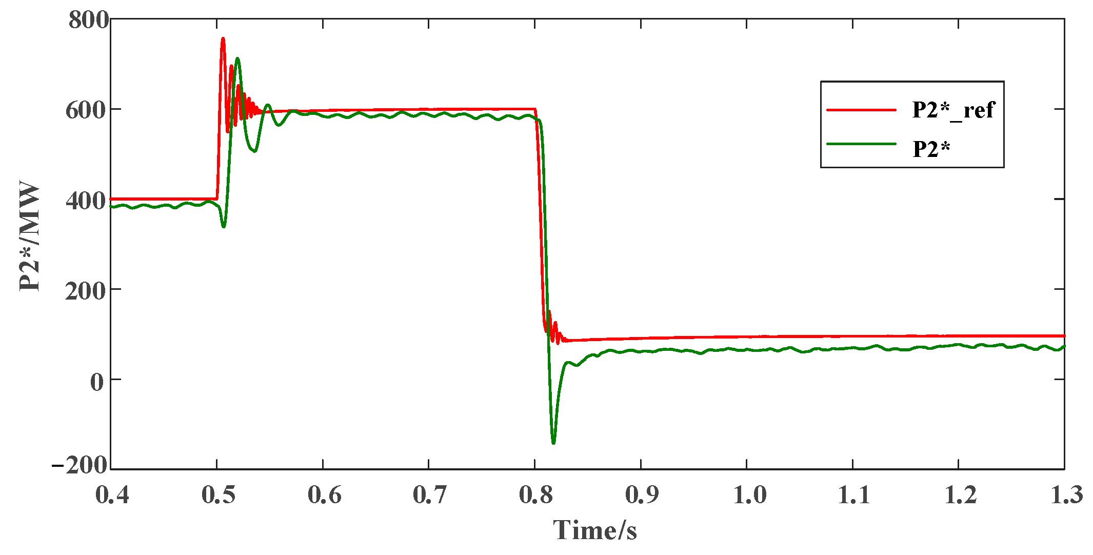
Then, the reference values of output power are adjusted at the sending end converter stations VSC1 and VSC3, which are controlled by fixed active power, and the two converter stations VSC1 and VSC3 are set to output 400 MW of active power at 0.1 s. Then, the active power output is increased to 600 MW at 0.5 s, and finally the active power output is restored to 400 MW at 0.8 s. These values are used to simulate the situation of the system when the system has a large power change.
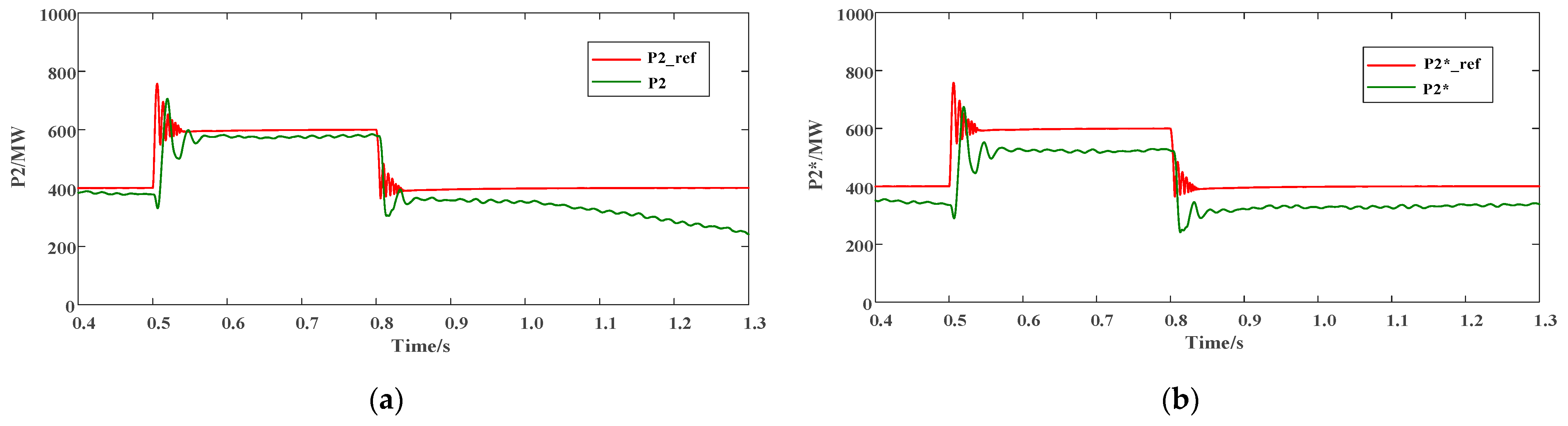
Taking the converter station VSC2 as an example,
Figure 14a shows the received power waveform before improvement,
represents the theoretical value of the received power, and
represents the actual value of the received power before the improvement of droop control. It can be seen from
Figure 14a that the droop controller loses the ability to regulate the power when there is a large power change in the converter station before the improvement, and the converter station is gradually destabilized after running for some time.
Figure 14b shows the received power waveform of VSC2 after the droop control improvement, where
is the theoretical value of the received power and
is the actual value of the received power after the droop control improvement. From
Figure 14b, it can be observed that by correcting the droop factor, the system is realized to be able to operate stably under large-scale power fluctuations, and the power regulation capability of the converter station is enhanced.
Figure 15 shows the comparison of the actual value of the received power of VSC2 before and after the improvement of the droop control,
is the actual received power before the improvement, and
is the actual received power after the improvement. The comparison between before and after improvement shows that the adaptive droop control method proposed in this paper improves the stability of the system during large-scale power fluctuations, and the ability to regulate the power is also enhanced.
If there is a high-power change, such as the converter station exiting operation, the normal operation of the system needs to be further verified. Therefore, at 0.8 s, the output power of VSC1 of the converter station is set to zero so that it can quit the operation, and at the same time, the output power of VSC3 is reduced to 200 MW, and the waveform of the output power of VSC1 of the converter station is shown in
Figure 16.
The received power waveform of converter station VSC2 is shown in
Figure 17, and the simulation results show that the actual received power
of VSC2 realizes a better tracking to the reference power
.
This indicates that the system with adaptive droop control can still operate stably after VSC1 of the converter station is out of operation, which satisfies the N-1 principle, which means that the system can maintain synchronous operation when any converter station is out of operation due to power overrun or failure.
Figure 18 displays the DC voltage variation at the VSC2 port of the converter station. It reveals that the decommissioning of VSC1 results in a maximum voltage deviation of 18 kV.
As illustrated in
Figure 19, at 0.5 s, both power and voltage experience a slight increase. According to Equation (9), it can be inferred that when
, the adaptive factor shows a decreasing trend, leading to a reduction in the improved droop factor through the controller. At 0.8 s, due to high-power changes, such as the withdrawal of VSC1 from operation at the converter station, there was a significant fluctuation in voltage, resulting in a maximum voltage deviation
reaching 18 kV. According to Equation (9), it can be inferred that when
, the adaptive factor shows an increasing trend, and the improved droop factor will also increase. Thus, it can be concluded that the adjustment of the droop factor by adaptive droop control meets the pre-set requirements.
5. Conclusions
In this paper, the flexible DC transmission system based on voltage droop control is studied, and the four-terminal flexible DC transmission system is taken as an example to establish its equivalent circuit model and related mathematical model and derive the power allocation ratio relation equation considering the resistance of the transmission line. Furthermore, the paper establishes the electromagnetic transient model of the four-terminal flexible DC transmission system in PSCAD, and different droop factors are set for the droop control station at the receiving end to observe the actual output power of the converter station under different working conditions. The simulation results are then compared with the theoretical values calculated by the deduced relation equation. The accuracy of the power distribution derivation for the droop control station was verified through these simulation results.
However, the traditional droop control with fixed droop factors is not flexible enough in a transmission system where power changes frequently. To address this, this paper proposes an adaptive droop control strategy based on the traditional droop control to optimize the droop controller. The main way is to detect the DC voltage deviation caused by power fluctuation and adaptively adjust the droop factor within a certain range. This approach allows the droop control to effectively respond to different working conditions and improve the controller’s ability to regulate power fluctuation.
Finally, a PSCAD simulation is used to compare the received power before and after the droop control improvement, and it is discovered that the proposed adaptive droop control successfully solves the problem that the traditional droop controller loses its power regulation ability under large-scale power fluctuations so that the system can operate stably. The droop factor can be adjusted adaptively in terms of its size according to the preselected parameters. This enhances the ability to regulate power.


