Review

Comprehensive Review of Liquid Air Energy Storage (LAES) Technologies

School of Mechanical and Design Engineering, University of Portsmouth, Portsmouth PO1 3DJ, UK
*
Author to whom correspondence should be addressed.
Energies 2023, 16(17), 6216; https://doi.org/10.3390/en16176216
Submission received: 31 July 2023 / Revised: 25 August 2023 / Accepted: 26 August 2023 / Published: 27 August 2023
(This article belongs to the Special Issue Advances in Thermal Energy Storage and Applications)

Abstract

:
In recent years, liquid air energy storage (LAES) has gained prominence as an alternative to existing large-scale electrical energy storage solutions such as compressed air (CAES) and pumped hydro energy storage (PHES), especially in the context of medium-to-long-term storage. LAES offers a high volumetric energy density, surpassing the geographical constraints that hinder current mature energy storage technologies. The basic principle of LAES involves liquefying and storing air to be utilized later for electricity generation. Although the liquefaction of air has been studied for many years, the concept of using LAES “cryogenics” as an energy storage method was initially proposed in 1977 and has recently gained renewed attention. With the growing need for alternative energy storage methods, researchers have increasingly explored the potential of cryogenic media, leading to the development of the first LAES pilot plant and a growing body of research on LAES systems. However, one notable drawback of LAES is its relatively low round-trip efficiency, estimated to be around 50–60% for large-scale systems. However, due to its thermo-mechanical nature, LAES offers versatility and can be easily integrated with other thermal energy systems or energy sources across a wide range of applications. Most of the existing literature on LAES focuses on thermodynamic and economic analyses, examining various LAES configurations, and there is a clear lack of experimental studies in this field. This paper aims to conduct a comprehensive review of LAES technology, with a focus on the performance enhancement of these systems. Future perspectives indicate that hybrid LAES solutions, incorporating efficient waste energy recovery sections, hold the most promise for enhancing the tech-no-economic performance of standalone LAES systems.

1. Introduction

In recent years, there has been a significant increase in the utilization of renewable energy sources, specifically wind power and solar photovoltaic technology, driven by the goal of decarbonizing the energy sector. According to the International Energy Agency (IEA), renewable sources accounted for 29% of global electricity generation in 2020 [1]. Projections indicate that this percentage will rise to 49% by 2030 [1]. However, a key limitation of renewable energy sources is their intermittent nature, which hampers their ability to provide a consistent and stable power supply. This intermittency creates a mismatch between the energy generated and the demand on the grid. To address this challenge, energy storage systems have emerged as a viable solution [2,3,4]. Thermal energy storage technologies are currently available at various stages of development. In conventional large-scale energy storage applications, PHES and CAES are considered to be the most common technologies. These technologies are mature technology for large-scale and medium-to-long-term storage applications and are available on the commercial market at relatively low costs [4]. The low energy density of these systems and their geographical restrictions have prompted attention to modern technologies that have been developed to overcome these drawbacks [2]. LAES systems are currently gaining increasing attention from academia and industry due to their advantages over alternative technologies designed for the purpose of large-scale energy storage [5]. LAES offers a range of notable benefits: firstly, it has the advantage of not being limited by geographical restrictions, unlike alternatives such as CAES and PHES, where large storage facilities typically require large natural storage capacity. Secondly, it relies on readily available, off-the-shelf components commonly employed in various industrial applications. Thirdly, it requires significantly less storage space compared to CAES, with a reduction of approximately 700 times [5,6,7,8]. The utilization of both hot and cold energy recovery cycles in the LAES system contributes to achieving a higher round-trip efficiency (RTE); the RTE is defined as the ratio between the heat input and the heat output during the charging and discharging processes [9]. Furthermore, locating LAES systems in proximity to other energy conversion processes can help alleviate the need for supplementary pipelines and the associated costs. Therefore, LAES demonstrates substantial promise as a viable option for large-scale applications [9]. Table 1 provides an overview of the technical characteristics of energy storage systems for large-scale applications.

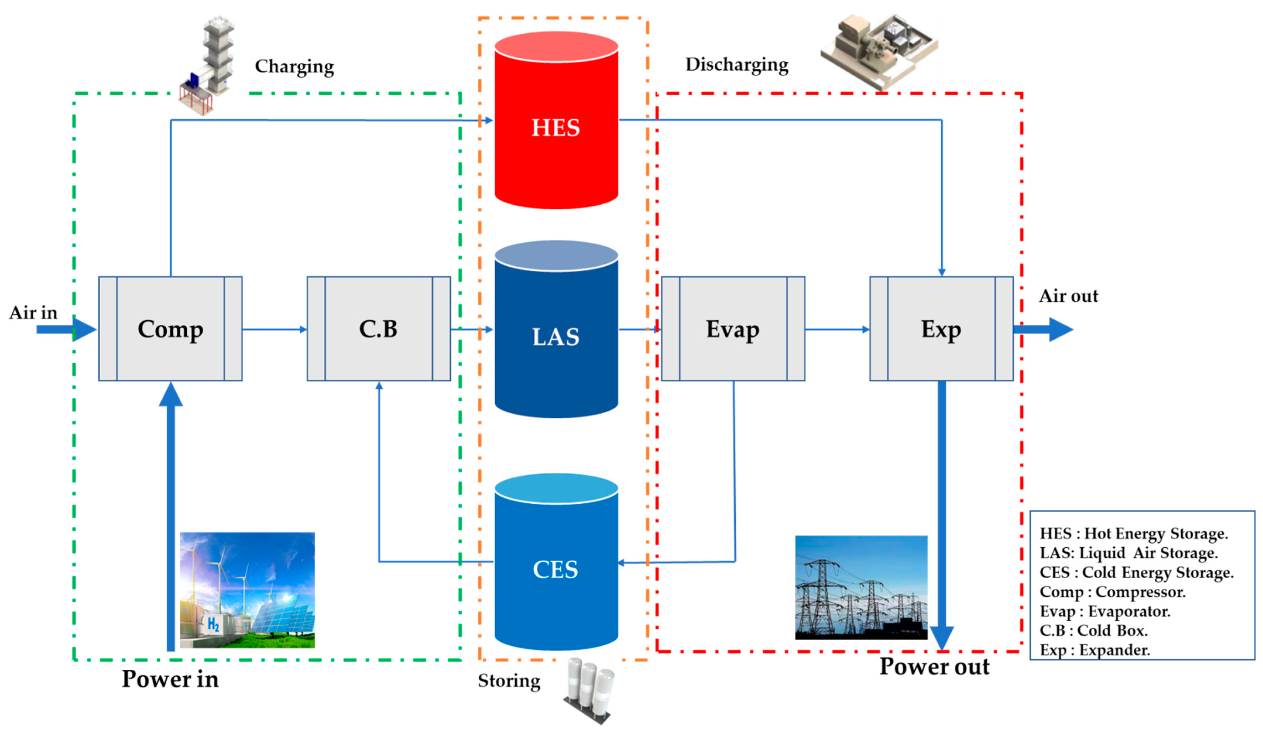
2. LAES Basic Principles

LAES is a technique used to store liquefied air in a large-scale system. Similar to CAES systems, LAES technology is charged using surplus grid electricity and discharged during periods of high electrical demand [10,11,12,13]. Through LAES, which acts as a buffer for the electrical system, the integrability and availability of various renewable energy sources can be improved.
The LAES system consists of three main cycles: the charging cycle, the storing cycle, and the discharge cycle, as illustrated in Figure 1. The charging system (gas liquefaction process) consists of an air liquefier that uses excess electrical energy at off-peak times to draw air from the surroundings, and the air is cooled down to (−196 °C) during this stage to liquefy 700 liters of ambient air into 1 liter of liquid air. Atmospheric air is pressurized through the compressor using excess electricity. During the compression stage, the storage tank can be used to superheat the air in the discharging process to increase power output. A TES (thermal energy storage) material such as thermal oil, hot water, or glycol is typically used. In the storing cycle, liquefied air is stored at low pressure in an insulated tank, which functions as the energy store. A cold box is used to cool compressed air using come-around air, and a cold storage tank can be filled with liquid-phase materials such as propane and methanol, as well as solid-phase materials such as pebbles and rocks. During the discharge cycle, cold energy is recovered from liquid air storage. To recover the power, liquid air is pumped into the high-pressure evaporator and heated. During the evaporation stage, the high-grade cold exergy is recovered and stored in a cold storage tank, which can be reused in the cooling-down process, reducing power consumption at the charging system, where liquid air is produced through the expansion of air. The heat storage tank then heats the air, which is used to generate electricity through air turbines at high demand. An additional cycle can be added to improve the system efficiency and reduce the energy demand for producing liquid air, called cold recycle. In this stage, the cold gas is exhausted during the power recovery process and recycled back into the first stage (gas liquefaction process).
LAES has a number of benefits over competing solutions, including higher energy densities and no site restrictions, as previously mentioned. Due to the cryogenic temperatures of liquid air [11], a significant portion of heat sources available at ambient temperatures can be utilized to drive the power generation cycle. As a result, not only is combustion eliminated and carbon emissions reduced, but the LAES process is also able to recover low-temperature streams, such as waste heat. LAES can be integrated with external sources of heat and cold, resulting in synergies and symbioses with other processes, such as those occurring at nearby industrial sites.
Recently, efforts have been made to commercialize and enhance LAES conversion efficiency, which was considered for a long time to be a significant challenge. This has been driven primarily as a result of the promising characteristics of the technology and its potential for technical advancement [11]. A standalone LAES can achieve an efficiency of up to 57% [6]. In addition to this, improving the system’s efficiency can add to its economic benefits and wide applications.
LAES technology is categorized into two types: standalone LAES systems and hybrid LAES systems. Standalone systems only contain the basic LAES layouts. Only electricity is used as an energy source for input and output; air and heat carriers are the only fluids used in the LAES process. Hybrid systems incorporate external processes utilizing cold or hot thermal streams from external fluids. Hybrid systems can also incorporate external processes utilizing cold or hot thermal streams from external fluids. Energy can now be extracted from fuel in the form of electricity, chemical energy, cold, and heat.
The main difference between standalone LAES and hybrid LAES lies in their operational characteristics and integration with other energy storage technologies. See Table 2.
By defining standalone LAES, as well as hybrid LAES, in a formal manner, it is possible to distinguish between applications where LAES functions as a standalone self-sufficient storage vessel and applications where LAES is integrated with external processes. The performance of the plant must be analyzed accordingly as a result of this distinction.
Standalone LAES systems offer independence and flexibility, making them suitable for off-grid or remote areas. On the other hand, hybrid LAES systems leverage the benefits of liquid air energy storage while integrating it with other energy sources, thereby increasing efficiency, load balancing capabilities, and waste heat utilization. The choice between standalone and hybrid LAES systems depends on specific energy requirements, grid connectivity, available energy sources, and environmental considerations.

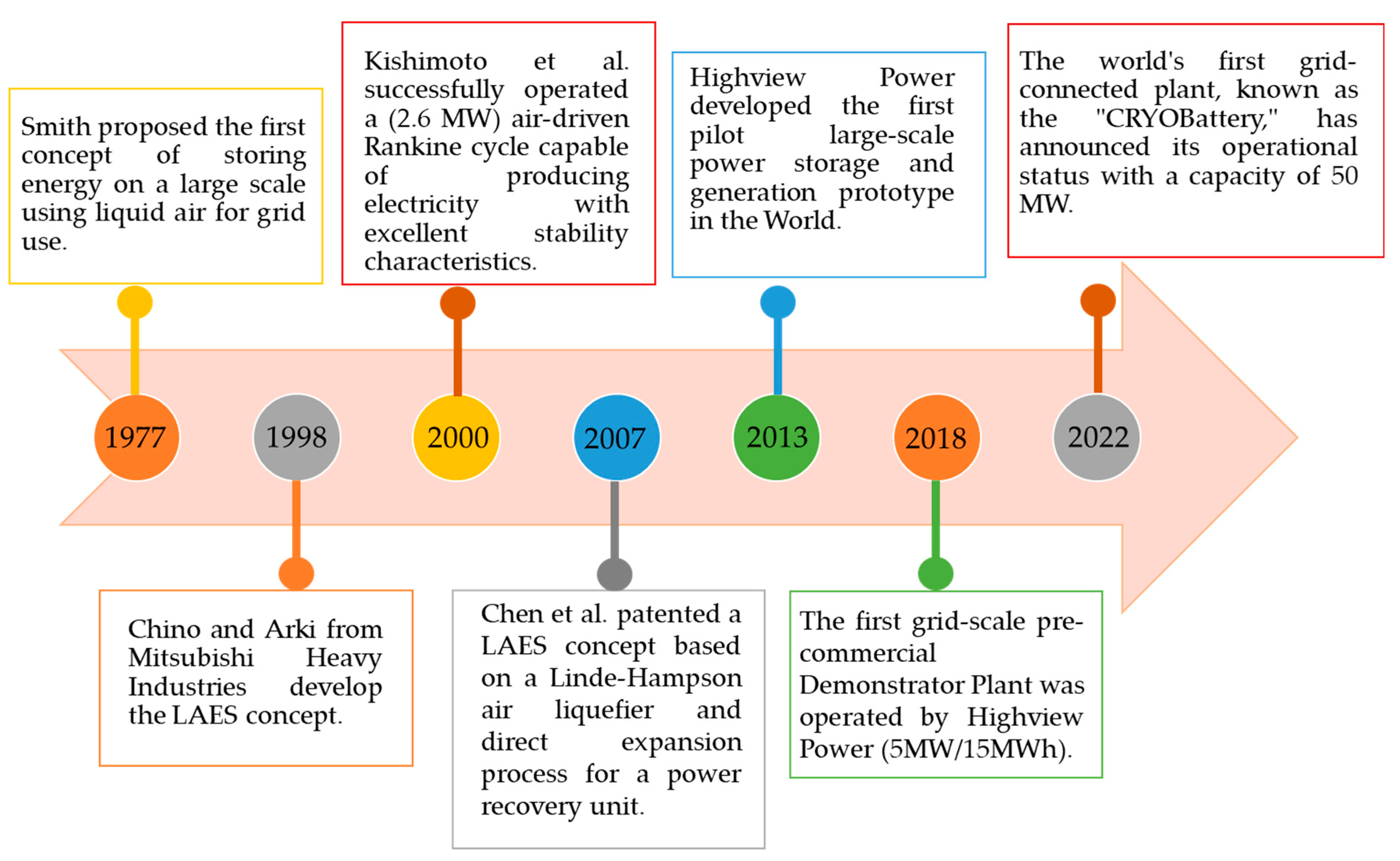
3. LAES Historical Background

Dating back to the nineteenth century, the process involved in the liquefaction of air and gases is generally well known. When liquefied, air is separated into its components—primarily liquid oxygen and liquid nitrogen—which have numerous industrial and medical applications. Several attempts were made, beginning in the early twentieth century, to use cryogenic media as an alternative energy source, primarily for transportation [14,15]. However, the concept of storing energy on a large scale with liquid air for grid use was initially proposed by Smith in 1977 [15]. According to Smith’s [16] research, adiabatic expansion and compression processes at 1048 K and 85 bars yielded 72% efficiency.
In 1998, Chino and Araki [17] drew inspiration from Smith’s LAES concept with a focus on simplifying the design of the regenerator (cold energy storage). Specifically, their proposed system involved the production of liquid air during off-peak hours, which was subsequently utilized to fuel a combustor in a gas turbine during peak hours. This approach allowed for efficient energy utilization and storage. The system was presented in two possible configurations: a one-stage setup and a more complex two-stage process configuration [17]. In 2000, Kishimoto et al. [18] successfully operated a (2.6 MW) air-driven Rankine cycle capable of producing electricity with excellent stability characteristics. To improve gas liquefaction, Hitachi researchers (Chino and Araki) proposed a combustor and concrete regenerator design, which they predicted would achieve up to 70% efficiency [19]. With the cooperation of the University of Leeds researchers, Highview Power has been conducting in-depth research into LAES systems since 2006. There have been numerous studies conducted on liquid air production systems, expansion, and power generation in the turbine, as well as its integration with heat losses of other systems, and have achieved acceptable economic and technical results [14,20]. In 2007, Chen et al. [21] patented a LAES concept based on a Linde–Hampson air liquefier and direct expansion process for a power recovery unit. After that, Highview Power developed the first large-scale power storage and generation prototype in 2013, which generated 300 kW of electrical power. It is possible to store up to 100 tons of liquid air in isolation if the liquid air storage tank is equipped with a 300 kW engine and the pressure is less than 10 bar [15,22]. When heated compressed air is passed through the turbine, the efficiency of the pilot test sample increases with the amount of heat stored in the system, reaching an efficiency of about 60% (AC to AC) [15]. In June 2018, another 5 MW, 15 MWh pre-commercial plants by Highview Power became operational [22], laying the grounds for the deployment of two LAES 50 MW plants (known as CRY Battery) in the United Kingdom and the United States, which were recently introduced by the same company [23]; these are the world’s first grid-connected LAES plants. Furthermore, several international projects are underway to promote further development, research, and characterization of LAES technology, including the Cryo-Hub project [24], as well as the IEA Energy Storage Task project. Figure 2 shows the LAES historical timeline.

4. LAES Performance Improvement Methods

Gas liquefaction and power-generating technologies discussed above, acted as the basis for the development of the LAES. It is reported that a large-scale standalone LAES has an expected round-trip efficiency of (50–60%) [25]. The key concept to improve LAES efficiency can be achieved by enhancing the overall system configuration, optimizing the thermal energy storage capabilities, and integrating with external heat sources.
Recently, much research has been done on efficiency enhancement. In this section, the three key methods for improving efficiency are discussed: (I) system configuration optimization, (II) enhanced thermal energy storage, and (III) system integration. The system configuration optimization improves performance by reconfiguring the system to obtain a more optimal one while appraising the LAES’s working parameters.

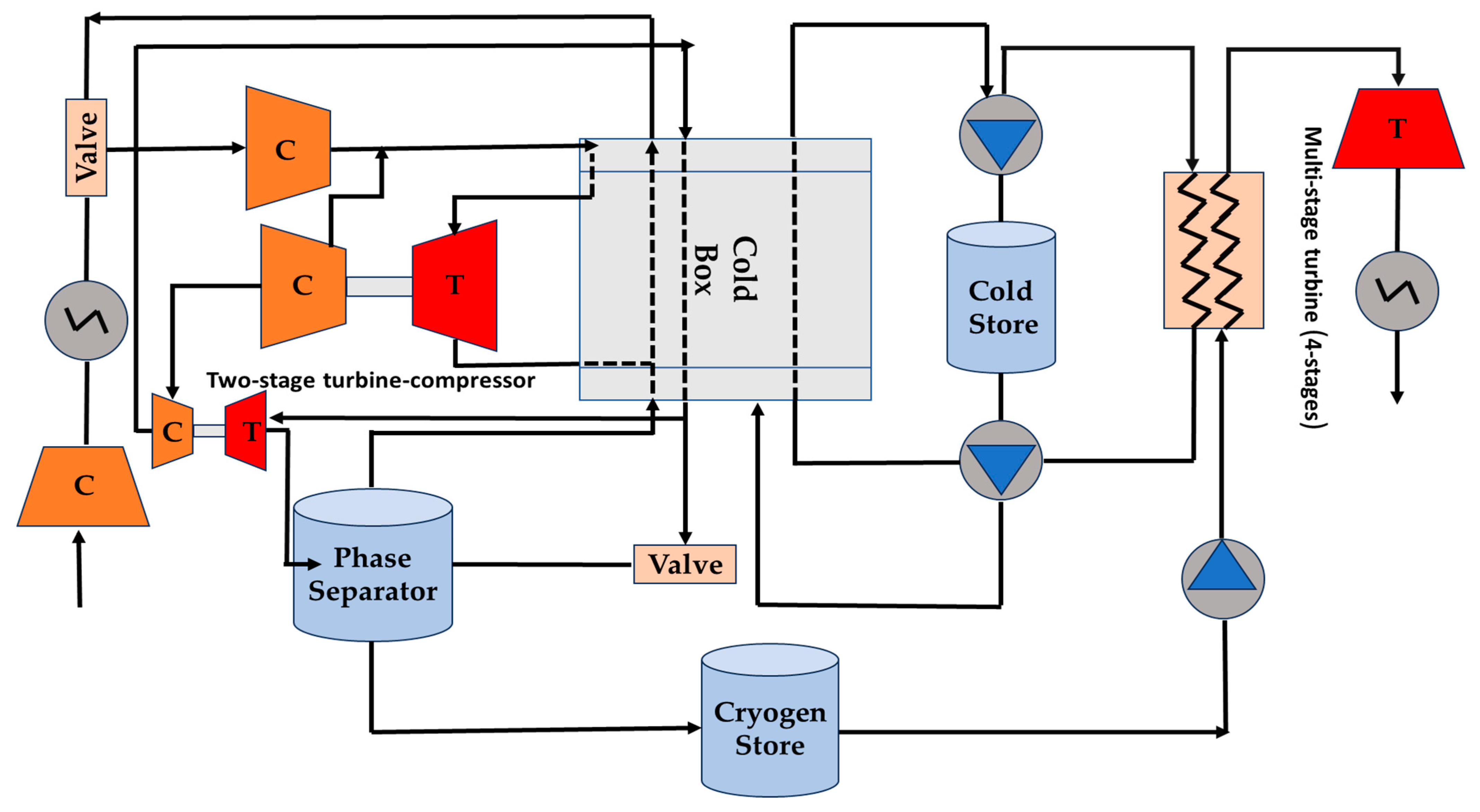
4.1. System Configuration and Optimisation

To enhance the performance of the LAES system, significant efforts have been dedicated to improvement. A study conducted by Morgan et al. [26] explored performance enhancement by optimizing the gas liquefaction process using a conventional two-turbine Claude system operating in parallel (Figure 3). However, this cycle encountered a pinch in the cold box, which restricted the effective utilization of cold energy. To overcome this limitation, a three-turbine cycle was proposed as a replacement for the single cold turbine [6], resulting in an increase from 47% to 57% in round-trip efficiency.
A study conducted by Abdo et al. [27] compared three cryogenic energy storage cycles: Linde-Hampson, Claude, and Collins. All three cycles produced similar amounts of system power, but the Claude cycle had a superior cost-benefit ratio over the others. Guizzi et al. [28] examined using a LAES system that recirculates cold thermal energy from regasification and hot thermal energy from adiabatic compression. Their results led to a 54.4% RTE. Chino et al. [17] introduced a combustor combined with a LAES system. As a result of the combustion of oxygen, natural gas, and compressed air, the temperature of the compressed air at the gas turbine’s inlet is raised. When compared to conventional LAES with a combustor, it was found that the output power was much higher. In addition, they investigated the use of cold recovery in gas liquefaction and found that it had an RTE of 70%, higher than the 60% efficiency of LAES standalone. Antonelli et al. [29] compared the LAES with and without fuel combustion using natural gas as fuel. According to their findings, the LAES was able to achieve a maximum fuel efficiency of 105% and a maximum round trip efficiency (RTE) of 76% by using fuel combustion. Krawczyk et al. [30] conducted a thermodynamic analysis of both the CAES and LAES using Aspen HYSYS software, where compressed air is heated to 1300 °C and then expanded in order to generate electricity, utilizing fuel combustion as the heat source. During their research, they demonstrated that LAES technology outperformed compressed air energy storage by 15% in terms of round-trip efficiency. LAES has a lower round-trip efficiency than other fuel combustion systems due to the fact that the optimization of either the cold side or the hot side of heat transfer has not been considered. External heat sources can greatly increase output power. However, they frequently result in higher running costs and CO2 emissions. As a result, it is important to carefully balance the costs (both financial and environmental) associated with an efficiency increase.
Another approach to increase efficiency is to combine the conventional LAES cycle with other cycles. According to Antonelli et al. [29], integrating a conventional LAES cycle with an ORC (organic Rankine cycle) can result in a maximum RTE of 77%. To reduce the specific power consumption of the compressor, the authors developed another hybrid LAES system using an open Brayton cycle. A Brayton cycle is employed in this LAES to cool the working fluid to a low temperature through recuperation; the cooling energy from the evaporation of liquid air is used in this process. Such a hybrid system’s round-trip efficiency might reach a maximum of 90%, which makes this method highly desirable for enhancing LAES performance. Despite its advantages, the hybrid LAES has the same drawbacks as the external heat source in terms of higher CO2 emissions and operating costs. This makes combustion-free LAES the better option.
Rather than using a pressurized container for storing compressed air, Kantharaj [31,32] suggested combining liquid air and compressed air as a hybrid energy storage system. The researchers reported that the hybrid system’s round-trip efficiency may be as high as 53%. For the purpose of improving the standalone cryogenic energy storage system, Hamdy et al. [33] employed an indirect Rankine cycle to utilize the cold produced by liquid air evaporation. With the inclusion of this additional cycle, the discharge process’s specific power output increased by 25%, and round-trip efficiency increased by 40%.

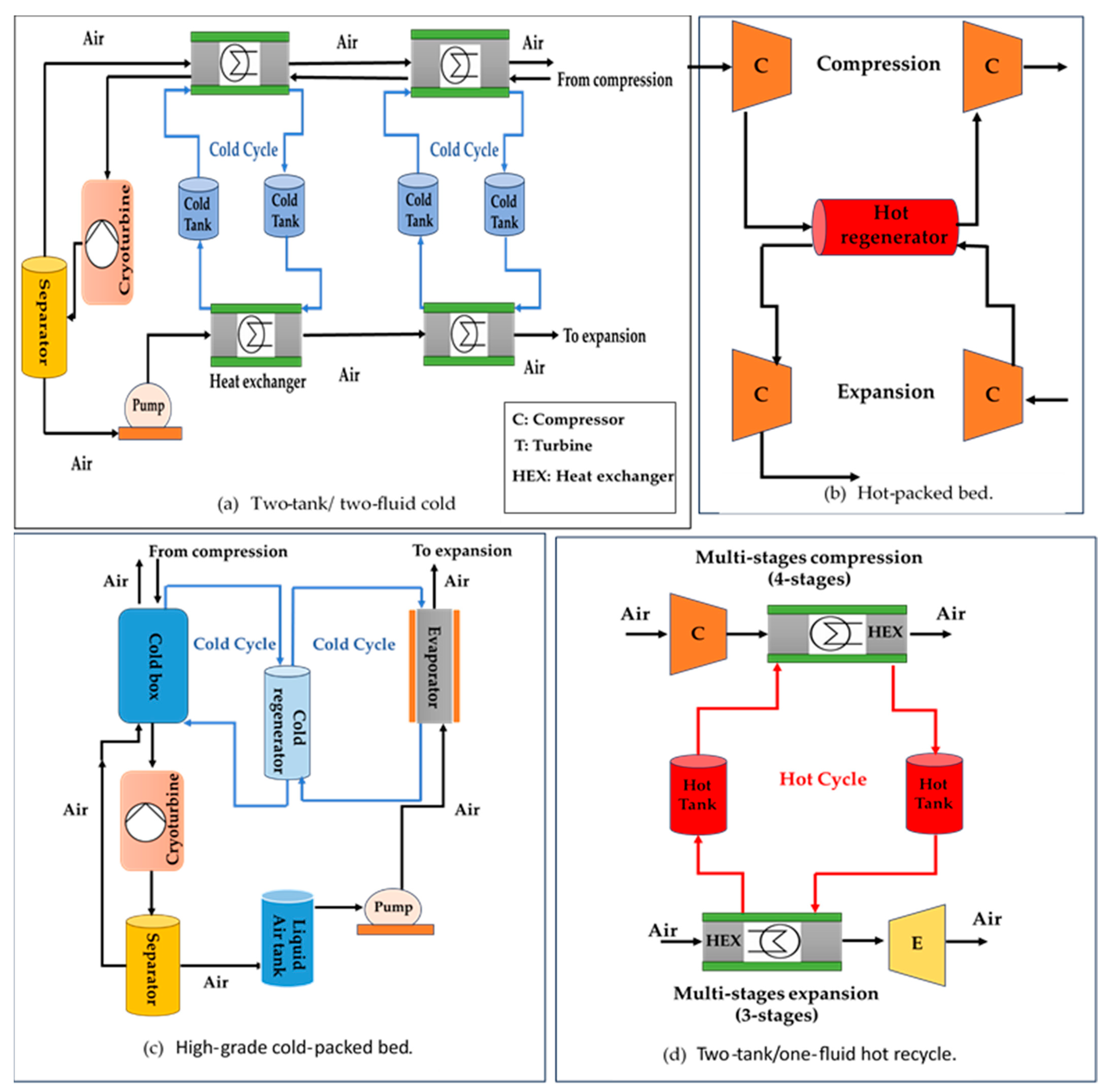
4.2. Thermal Energy Storage Enhancements

According to the definition of a LAES standalone system, the charge and discharge processes do not require the use of any external heating or cooling sources. Thermal energy storage is typically used by the standalone LAES to recover cold/heat from the expansion and compression processes. Compression heat can range from 150 °C to 300 °C or even higher depending on the compression ratio and the number of compression stages, while liquid air evaporation can produce cold energy as low as −150 °C.
TES technologies may play an important role in the efficient use of compression heat and expansion cold during the charging and discharging of the LAES process in order to overcome demand–supply mismatches [34]. Packed bed storage is a TES method and has attracted the most research; this serves as a direct contact heat exchanger and an energy storage device and is a very reliable and reasonably inexpensive procedure. A suitable thermal storage device could be employed during the operation of LAES to provide both heat and cold recovery.
A packed bed was described [35,36] as a mathematical model based on assumptions of the gas-phase temperature and solid-phase temperature, and the model was used to investigate the effects of porosity, particle diameter, and inlet velocity. They found that increasing the porosity led to a quicker charge time but reserved the thermal storage capacity and charge efficiency. Reducing the particle diameter increased the charge efficiency without having any significant effect on the thermal storage capacity. The performance was found to be less sensitive to the inlet velocity, with an increase in the velocity reducing the charge efficiency.
A novel liquid air energy storage (LAES) system using packed beds for thermal storage was investigated and analyzed by Peng et al. [37]. A mathematical model was developed to explore the impact of various parameters on the performance of the system. According to the results, the LAES system could achieve a round-trip efficiency of 50% and 62% with an appropriate parametric design and existing technologies. The inlet temperature of cold boxes and the charge and discharge pressures had significant effects on both the temperature distribution inside the cold boxes and the overall round-trip efficiency. Increasing the inlet temperature of the cold box had a negative effect on system efficiency, while increasing the charge and discharge pressures had a positive impact. For the purpose of improving cold recovery efficiency, Sciacovelli et al. [38] conducted a dynamic analysis of a 100 MW LAES system with a 300 MWh storage capacity in a direct-contact storage device packed with rocks and pebbles. Their study examined a novel standalone LAES (using a packed-bed TES) that recovers cold energy from liquid air evaporation and stored compression energy in a diathermic hot thermal storage. The study found that RTE between 50–60% was achievable.

4.3. Integration of LAES

Integrating LAES with external thermal sources can enhance its performance and make it a more versatile energy storage system. For instance, gas turbines can significantly increase their shaft work during discharging cycles by using a natural gas combustor [17,29,30]. As well as generating cold energy for pre-cooling compressed air to increase liquid air production, a refrigeration cycle can be used to cool compressed air at the compressors’ inlets to reduce the amount of specific power required.
A geographically and mechanically combined LAES system interconnects the LAES with industrial systems, storing and releasing energy as needed. Industrial processes can provide the necessary heat or cold energy. As most thermal energy cannot be effectively employed in industrial operations, there are financial benefits for both the LAES operator and the industrial partners. Numerous approaches have been applied to integrate LAES with a variety of processes, including Liquified Natural Gas (LNG) regasification, wind power generation, nuclear power production, and solar power generation. Li et al. [39] suggested integrating LAES with nuclear power plants (NPP), whereby the NPP’s load can be significantly shifted by the integrated system, allowing the NPP to continue operating at its rated power during times of lower demand when the excess power is used to power the LAES charging cycle. Next, when the demand for electricity is considerably greater than the rated power, the discharge cycle is initiated, and liquid air is converted into electricity once again. There is a reported RTE of over 70% for the integrated LAES-NPP system, resulting in 2.7 times the rated NPP power as net output.
Lee et al. [40] examined the feasibility of integrating LNG regasification with cryogenic energy storage. A number of turbines are driven by hot natural gas in order to perform additional work and reduce the air compressors’ power consumption. Their findings suggested that both the air storage and release processes had much greater exergy efficiencies, at 94.2% and 61.1%, respectively. Meanwhile, Kim et al. [41] suggested combining LAES and LNG regasification in a distributed energy generation system. Their study showed that the exergy efficiency was 64.2% and the round-trip efficiency was 70%. Table 3 provides an overview of the performance of LAES systems in the literature.
The table clearly shows that using a combination of cold and hot thermal energy sources significantly increases standalone LAES systems’ round-trip efficiency.

4.4. Hot and Cold Thermal Recycle

Hot and cold energy streams are produced at certain LAES charge and discharge stages and are required at other stages. In particular, the high-grade cold produced during air evaporation can be utilized to support air liquefaction, and reheating can utilise compression heat as a thermal reservoir at high temperatures. The performance of the plant depends on the efficient internal utilisation of such streams inside the LAES process, particularly when it comes to cold recycling. Compared to the loss of heat in the hot recycle, the losses of cold energy had a seven times greater influence on LAES efficiency [44]. Different configurations of TES, storage media, and Heat Transfer Fluids (HTF) have been used in a number of thermal recycling systems; the most common ones are shown in Figure 4 [8,13,46,47].
Compared to the initial proposal of reducing liquefaction work by pre-cooling the upstream compressed air, it is found that combining high-grade cold from liquid air evaporation with additional cooling in the cold box enhances LAES performance the most. Initially, solid regenerator-type storage systems were proposed for cold recycling since evaporation temperatures (∼90 K) require material durability at cryogenic conditions. One such system is a solid matrix made of 304 stainless steel [16], while another is a packed bed of rocks [6] and concrete pebbles inserted into steel pipes [17]. The capability of direct heat transfer is considered one of the most important features of regenerators, in addition to the availability of storage media, thermal stability, and low cost. Cryogenic packed beds have primarily been examined experimentally [48] or using dynamic numerical models [49]. The difficulties of extrapolating thermal properties in the cryogenic range, as well as their variation with temperature, make experimental results highly valuable in this context [49]. In a comparison of nine different solid materials suitable for use at low temperatures (0 to −196 °C), Hüttermann and Span [50] found that quartzite ranked among the most efficient materials for cold TES devices in terms of energy efficiency and exergy. It has been reported in experimental measurements under cyclic operation for cryogenic packed beds to reach up to 95% [51]. Low losses and high efficiency have been demonstrated for regenerators. There are, however, a number of challenges associated with the development of a thermal front in the regenerators (thermocline) that require greater storage volumes and result in dynamic temperature changes at the outlet of the TES [52]. To mitigate this effect, many technical solutions have been introduced [53] and adopted [6], but these come at a higher cost and require greater complexity of the TES device.
The literature has also suggested liquid TES solutions for cold recycling, for example, propane (R290) [28,54], methanol (R218), and methanol [28,33]. A variety of liquids are being proposed for cold storage at rising temperatures since no liquid is suitable in the range of (0 to −196 °C). Using vermiculite insulation in a small-scale test facility, a propane-R123 configuration presented 91% thermal efficiency but with higher thermal losses in comparison to solid-packed beds. In the future, R123 may replace methanol because it is liquid at a wide range of temperatures [55]. Compactness is liquid TES’s main benefit [28]. Oxygen must, however, be kept apart from liquid hydrocarbons in the liquid streams for safety reasons [9].
By utilizing the compression heat released during liquefaction, hot recycling is primarily responsible for raising the temperature of the turbine inlet. Not all rejected heat may be used in this situation, and an ambient heat exchanger is often rejected in a circuit. In this scenario, two tanks are usually used with liquid TES; however, a hot packed-bed TES has only been evaluated in one study, similar to the adiabatic CAES system [56]. It is also possible to use two different types of fluids (for example, oil and water) when the temperature rises [8]; this can produce a temperature glide that is better suited for coupling with external power cycles. Heat carriers like molten salts can also be used, as in [57]; however, here, two fluids were needed: mineral oil storing the low-temperature heat and solar salt storing the compression heat above 220 °C. Table 4 [11] lists the common LAES thermal storage media, along with their thermo-physical properties and associated technology solutions.
Cold recycling plays an important role in LAES performance; options for cold TES tend to favor thermally efficient solid regenerators. In hot recycle applications, two-tank liquid TESs are preferable because they allow for stable turbine inlet temperatures during LAES discharge, where the appropriate storage media and fluid are determined by the LAES discharge temperature. There may be additional justification for design decisions based on a techno-economic and cost factors comparison of the TES alternatives, but such a study has not yet been conducted for LAES [58].

4.5. Summary of Approaches for LAES Enhancement

A range of approaches have been applied to improve the performance of LAES technologies. These include considering the TES media, as shown in Table 4, and considering enhanced energy storage, for example, the use of a packed bed [38] can increase the RTE to 60%. An improved RTE of 57% was found when multi-stage turbines were introduced [6], and studies involving heat/cold recovery achieved an RTE of up to 70% [17]. Further enhancements involved combining with other cycles, such as the ORC or Brayton, giving an improved RTE of 77% [29], combining with combustion [29], or integrating with an external source such as an NPP [4] or LNG regeneration [41] which have been shown to give an RTE of 76%, 70%, and 70%, respectively. These features can also be combined to give a further improvement; for example, combining an additional Brayton cycle with an integrated combustion process [13] gave an RTE of almost 130%.

5. LAES in the Literature

Using experimental evidence, Morgan et al. [26] found that increasing the pressure of the liquid air pump, increasing the temperature of the air that enters the turbine, and increasing the charge pressure of the air tank improved the efficiency of the system, enabled the system to supply more electricity than it received from the grid. The effects of temporary cold energy storage on the LAES system’s efficiency and performance have been investigated using dynamic modeling presented by Sciacovelli et al. [38]. The study showed that using packing beds for cold fluid storage improved RTE by approximately 50%. Liu et al. [25] investigated various cold thermal energy storage solutions in order to increase performance. According to the authors, there were advantages to using multi-component fluid cycles rather than two single fluid cycles (e.g., propane and methanol cycles) in terms of specific power consumption and liquid production. This was due to an improved temperature match at the cold box, which achieved an RTE of 64.7%. Other authors [9,42,50,59,60] have proposed similar approaches; studies examined cold storage devices in standalone LAES systems and concluded that they improved round-trip efficiency by up to 60%.
A number of other studies [28,60,61,62,63,64] have investigated the effect of the compressor turbine’s isentropic efficiency on the RTE of standalone LAES systems with internal thermal energy storage and the optimization of crucial parameters, including expansion and liquefaction pressures. Based on the findings of the studies, a round-trip efficiency of up to 55% could be achieved using conservative design parameters.
Dincer and Rosen [65] provided gas liquefaction and cryogenic system exergy analysis. Energy–exergy relationships were presented and calculated for a Linde–Hampson gas liquefaction system. Li et al. [39] combined an NPP with a cryogenic storage system (nitrogen or air) and published the load-shifting results. Air separation and liquefaction units have also been extensively researched, and air components (e.g., oxygen) are used in a variety of industrial applications, like coal-fired power plants or gas turbines [15,66].
LAES has recently been integrated into other energy systems with the aim of increasing its efficiency. In order to increase LAES power turbine inlet temperatures and improve system performance, Wu et al. [67] have developed a hybrid LAES system by combining a thermochemical energy storage (TCES) with a standalone LAES system utilizing the oxidation reactor’s waste heat. The study demonstrated an RTE of 47.7%. A LAES system coupled with an LNG regasification plant and a combined cycle power plant was investigated by Gao et al. [68], as the cold exergy generated by LNG regasification was used to reduce the power consumption of LAES compressors. Exhaust heat was used to heat the air before expansion. According to the authors, 47.8% of the exergy was obtained.
As part of a hybrid wind–solar–LAES system, Ji et al. [69] used electricity generated by a wind turbine to run air compressors and a solar collector to heat up and evaporate liquified air, resulting in a 44.2% exergy efficiency. Meanwhile, Kantharaj et al. [31] suggested a hybrid system combining standalone LAES and CAES systems. The study found that hybrid storage systems provide greater cost savings than standalone storage systems in spite of their lower RTE (42%). Park et al. [70] investigated the thermal integration of LAES with an NPP and successfully achieved an energy efficiency of 51%. Cetin et al. [43] have shown a novel LAES system combined with a geothermal power plant that has a round-trip efficiency of 46.7%. He et al. [71] suggested using LNG cold exergy in a cascade combination with district cooling and a cryogenic ORC, to supply the LAES compression process. The study resulted in a 73.9% exergy efficiency.
Park et al. [72] presented a new approach (which offers exergy efficiency of up to 54.9%) for recovering LNG cold exergy that would otherwise be wasted in the sea and reducing the exergy lost during natural gas liquefaction utilizing the cold exergy. Meanwhile, Tafone et al. [73] provided various LAES-ORC integrations designed to achieve an alternative use for waste heat derived from compressor aftercoolers and intercoolers with RTEs of approximately 52.9%. In addition, the LAES–ORC–absorption refrigeration cycle with a high RTE reaching 61.3% has been presented by Peng et al. [44]; the LAES compression train produces a significant amount of heat, which serves both as an absorption chiller and the heat source for the ORC.
A novel combination that includes heating, cooling, and electricity systems with an exergy efficiency of about 57% has been investigated by Xue et al. [74] by converting compression heat to district cooling through an absorption refrigeration process. Using LAES with Kalina and ORC cycles for recovering compression heat was discussed by Zhang et al. [75]. Due to the increased power generation, the systems reported 56.1% and 56.9% around-trip efficiency, respectively.
A limited number of publications have been published on the application of ORCs in cryogenic temperatures. An integrated LAES system that uses waste heat from the compression train as a heat source and liquid air as a sink was proposed by Hamdy et al. [33]. The integrated LAES system has an overall efficiency of 28.7% in addition to its 32.1% round-trip efficiency. A cryogenic ORC was integrated into an LAES system connected to gas turbines by Antonelli et al. [29]. The exhaust gas from the gas turbine worked as a heat source for the ORC as well as a superheater for the liquid air, whereas the liquid air from the tank served as the ORC’s heat sink. Due to the gas turbine exhaust gas temperature, LAES obtained a round-trip efficiency of 61.2%.
Li et al. [76] studied hybrid storage system integration with solar energy and cryogenic. Based on the results of this study, integrating this system with solar energy for heating air entering the turbine of the liquid air storage system would increase the total output of electrical energy by 30%. Based on the Linde–Hampson cycle, Xue et al. [64] examined the critical parameters affecting the efficiency of a LAES system using a choke valve for liquefaction, using thermodynamic analysis. Their findings indicate that LAES requires optimization and even careful analysis to achieve optimum performance and efficiency because it contains complexities and subtleties. Their discussion and conclusion also acknowledge that LAES systems are complex and challenging, and future studies on these systems should include optimization studies.

Performance of TES Systems with LAES

The literature has presented numerous research and study projects about LAES technology. Table 5 shows a summary of the most recent research on standalone and hybrid LAES systems.
From a methodological standpoint, the majority of the studies discussed conducting thermodynamic performance assessments for LAES systems (e.g., analyzing energy and exergy, modeling the LAES process, system optimization, and conducting parametric investigations). A variety of commercial and numerical simulation software was used, including gPROMS, ASPEN, COMSOL, ANSYS, and TRANSYS, as well as internal codes developed in MATLAB, EES, and other programs.
Many theoretical studies and configurations have been explored in the field of LAES technology. However, it is crucial to address the lack of experimental validation for simulated LAES systems. This validation is necessary to ensure the reliability and accuracy of the technology. One of the reasons behind the limited experimental validation is the significant investment required for LAES machinery, including the number of compressors and turbines, as well as the costs associated with engineering and design studies. These factors contribute to the challenge of conducting extensive experimental validation for LAES systems.

6. Conclusions

LAES technology has gained significant attention over the past decade due to its numerous benefits in improving thermal energy storage systems and reducing global carbon footprints. One advantage of this technology is its high energy storage density, coupled with its ability to operate independently of location constraints such as the need for a gravitational potential (in the case of PHES) or underground caves (as required for CAES). A large-scale standalone LAES can achieve 50–60% round-trip efficiency.
This paper provided a comprehensive overview of its advantages and challenges in the existing literature. It explores the properties of LAES, different types and processes, and investigates how the system can be integrated with other facilities to further enhance energy efficiency.
Besides that, the paper discussed the development of LAES, which is based on gas liquefaction and power generation technologies, based on three main methods of improving system efficiency: (I) optimizing system configuration, (II) improving thermal energy storage, and (III) integrating the system. System configuration optimization involves reconfiguring the setup to achieve better performance and evaluating the working parameters of the LAES.
Although LAES technology is considered commercially novel, it holds the potential for significant advancements in grid-level green electricity production. Consequently, further development and investigation are necessary to fully explore its capabilities and ensure its commercial viability.

Author Contributions

Conceptualization, J.R. and J.M.B.; methodology, A.M.R.; investigation, A.M.R.; writing—original draft preparation, A.M.R.; writing—review and editing, A.M.R., J.R. and J.M.B.; visualization, A.M.R.; supervision, J.R. and J.M.B.; project administration, J.R. and J.M.B. All authors have read and agreed to the published version of the manuscript.

Funding

This research received no external funding.

Data Availability Statement

Not applicable.

Conflicts of Interest

The authors declare no conflict of interest.

Abbreviations

CAEScompressed air energy storage
HTFheat transfer fluids
IEAInternational Energy Agency
LAESliquid air energy storage
LNGliquefied natural gas
NPPnuclear power plant
ORCorganic Rankine cycle
PHESpumped hydro energy storage
PTESpumped thermal energy storage
RTEround-trip efficiency
TCESthermochemical energy storage
TESthermal energy storage

References

  1. IEA. Renewables–Global Energy Review 2021–Analysis-IEA. Global Energy Review 2021. 2021. Available online: https://www.iea.org/reports/global-energy-review-2021/renewables (accessed on 11 May 2023).
  2. Rabi, A.M.; Radulovic, J.; Buick, J.M. Comprehensive Review of Compressed Air Energy Storage (CAES) Technologies. Thermo 2023, 3, 104–126. [Google Scholar] [CrossRef]
  3. Aneke, M.; Wang, M. Energy storage technologies and real life applications–A state of the art review. Appl. Energy 2016, 179, 350–377. [Google Scholar] [CrossRef]
  4. Rabi, A.M.; Radulovic, J.; Buick, J.M. Pumped Thermal Energy Storage Technology (PTES): Review. Thermo 2023, 3, 396–411. [Google Scholar] [CrossRef]
  5. O’Callaghan, O.; Donnellan, P. Liquid air energy storage systems: A review. Renew. Sustain. Energy Rev. 2021, 146, 111113. [Google Scholar] [CrossRef]
  6. Morgan, R.; Nelmes, S.; Gibson, E.; Brett, G. An analysis of a large-scale liquid air energy storage system. Proc. Inst. Civ. Eng. Energy 2015, 168, 135–144. [Google Scholar] [CrossRef]
  7. She, X.; Peng, X.; Nie, B.; Leng, G.; Zhang, X.; Weng, L.; Tong, L.; Zheng, L.; Wang, L.; Ding, Y. Enhancement of round trip efficiency of liquid air energy storage through effective utilization of heat of compression. Appl. Energy 2017, 206, 1632–1642. [Google Scholar] [CrossRef]
  8. Guo, H.; Xu, Y.; Chen, H.; Zhou, X. Thermodynamic characteristics of a novel supercritical compressed air energy storage system. Energy Convers. Manag. 2016, 115, 167–177. [Google Scholar] [CrossRef]
  9. Hüttermann, L.; Span, R.; Maas, P.; Scherer, V. Investigation of a liquid air energy storage (LAES) system with different cryogenic heat storage devices. Energy Procedia 2019, 158, 4410–4415. [Google Scholar] [CrossRef]
  10. BOC. Guidance on the Safe Operation of Vacuum Insulated Storage Tanks. VIEs and VITs. no. April. 2010. Available online: https://www.boconline.co.uk/en/images/Safe-Operation-of-VIEs-and-VITs_tcm410-39416.pdf (accessed on 20 July 2023).
  11. Vecchi, A.; Li, Y.; Ding, Y.; Mancarella, P.; Sciacovelli, A. Liquid air energy storage (LAES): A review on technology state-of-the-art, integration pathways and future perspectives. Adv. Appl. Energy 2021, 3, 100047. [Google Scholar] [CrossRef]
  12. Peng, X. Liquid Air Energy Storage: Process Optimization and Performance. Ph.D. Thesis, University of Birmingham, Birmingham, UK, September 2018. Available online: http://etheses.bham.ac.uk/id/eprint/8615 (accessed on 24 August 2023).
  13. Ding, Y.; Tong, L.; Zhang, P.; Li, Y.; Radcliffe, J.; Wang, L. Liquid Air Energy Storage; Elsevier Inc.: Amsterdam, The Netherlands, 2016. [Google Scholar] [CrossRef]
  14. Akhurst, M.; Atkins, A.; Uk, R.; Bruges, R.; Cooper, S.; Consulting, S. Liquid Air in the Energy and Transport Systems; The Centre for Low Carbon Futures: Brighton, UK, 2013. [Google Scholar]
  15. Ghaseminejad, A.; Hajidavalloo, E.; Azimi, A. Modeling, analyses, and assessment of a liquid air energy storage (LAES) system. Energy Equip. Syst. 2021, 9, 249–260. [Google Scholar] [CrossRef]
  16. Smith, E.M. STORAGE OF ELECTRICAL ENERGY USING SUPERCRITICAL LIQUID AIR. Inst. Mech. Eng. Proc. 1977, 191, 289–298. [Google Scholar] [CrossRef]
  17. Chino, K.; Araki, H. Evaluation of energy storage method using liquid air. Heat Transf.-Asian Res. 2000, 29, 347–357. [Google Scholar] [CrossRef]
  18. Kishimoto, K.; Hasegawa, K.; Asano, T. Development of Generator of Liquid Air Storage Energy System. Tech. Rev. Mitsubishi Heavy Ind. 1998, 35, 117–120. [Google Scholar]
  19. Araki, H.; Nakabaru, M.; Chino, K. Simulation of heat transfer in the cool storage unit of a liquid–air energy storage system. Heat Transf.-Asian Res. 2002, 31, 284–296. [Google Scholar] [CrossRef]
  20. Menezes, M.V.P.; Vilasboas, I.F.; Da Silva, J.A.M. Liquid Air Energy Storage System (LAES) Assisted by Cryogenic Air Rankine Cycle (ARC). Energies 2022, 15, 2730. [Google Scholar] [CrossRef]
  21. Chen, H.; Ding, Y.; Peters, T.; Berger, F. A Method of Storing Energy and a Cryogenic Energy Storage System. U.S. Patent WO2007096656A1, 30 August 2007. [Google Scholar]
  22. Peng, X.; She, X.; Li, C.; Luo, Y.; Zhang, T.; Li, Y.; Ding, Y. Liquid air energy storage flexibly coupled with LNG regasification for improving air liquefaction. Appl. Energy 2019, 250, 1190–1201. [Google Scholar] [CrossRef]
  23. Patel, S. Market Prospects Heating up for Cryogenic Energy Storage. Power. Available online: https://www.powermag.com/market-prospects-heating-up-for-cryogenic-energy-storage/ (accessed on 9 July 2023).
  24. Paneru, S.; Radcliffe, J. Cryogenic Energy Storage for Renewable Refrigeration and Power Supply, CryoHub. 2021. Available online: https://ior.org.uk/public/downloads/eunAX/D10.3+Active+role+in+engagement+strategy+to+communicate+S1.pdf (accessed on 24 August 2023).
  25. Liu, Z.; Kim, D.; Gundersen, T. Optimal recovery of thermal energy in liquid air energy storage. Energy 2022, 240, 122810. [Google Scholar] [CrossRef]
  26. Morgan, R.; Nelmes, S.; Gibson, E.; Brett, G. Liquid air energy storage-Analysis and first results from a pilot scale demonstration plant. Appl. Energy 2015, 137, 845–853. [Google Scholar] [CrossRef]
  27. Abdo, R.F.; Pedro, H.T.C.; Koury, R.N.N.; Machado, L.; Coimbra, C.F.M.; Porto, M.P. Performance evaluation of various cryogenic energy storage systems. Energy 2015, 90, 1024–1032. [Google Scholar] [CrossRef]
  28. Guizzi, G.L.; Manno, M.; Tolomei, L.M.; Vitali, R.M. Thermodynamic analysis of a liquid air energy storage system. Energy 2015, 93, 1639–1647. [Google Scholar] [CrossRef]
  29. Antonelli, M.; Barsali, S.; Desideri, U.; Paganucci, F.; Pasini, G. Liquid Air Energy Storage: 1 Potential and challenges of hybrid power plants. Appl. Energy 2017, 194, 522–529. [Google Scholar] [CrossRef]
  30. Krawczyk, P.; Szabłowski, Ł.; Karellas, S.; Kakaras, E.; Badyda, K. Comparative thermodynamic analysis of compressed air and liquid air energy storage systems. Energy 2018, 142, 46–54. [Google Scholar] [CrossRef]
  31. Kantharaj, B.; Garvey, S.; Pimm, A. Compressed air energy storage with liquid air capacity extension. Appl. Energy 2015, 157, 152–164. [Google Scholar] [CrossRef]
  32. Kantharaj, B.; Garvey, S.; Pimm, A. Thermodynamic analysis of a hybrid energy storage system based on compressed air and liquid air. Sustain. Energy Technol. Assess. 2015, 11, 159–164. [Google Scholar] [CrossRef]
  33. Hamdy, S.; Morosuk, T.; Tsatsaronis, G. Cryogenics-based energy storage: Evaluation of cold exergy recovery cycles. Energy 2017, 138, 1069–1080. [Google Scholar] [CrossRef]
  34. Gil, A.; Medrano, M.; Martorell, I.; Lázaro, A.; Dolado, P.; Zalba, B.; Cabeza, L.F. State of the art on high temperature thermal energy storage for power generation. Part 1—Concepts, materials and modellization. Renew. Sustain. Energy Rev. 2010, 14, 31–55. [Google Scholar] [CrossRef]
  35. Peng, H.; Dong, H.; Ling, X. Thermal investigation of PCM-based high temperature thermal energy storage in packed bed. Energy Convers Manag. 2014, 81, 420–427. [Google Scholar] [CrossRef]
  36. Peng, H.; Li, R.; Ling, X.; Dong, H. Modeling on heat storage performance of compressed air in a packed bed system. Appl. Energy 2015, 160, 1–9. [Google Scholar] [CrossRef]
  37. Peng, H.; Yang, Y.; Li, R.; Ling, X. Thermodynamic analysis of an improved adiabatic compressed air energy storage system. Appl. Energy 2016, 183, 1361–1373. [Google Scholar] [CrossRef]
  38. Sciacovelli, A.; Vecchi, A.; Ding, Y. Liquid air energy storage (LAES) with packed bed cold thermal storage–From component to system level performance through dynamic modelling. Appl. Energy 2017, 190, 84–98. [Google Scholar] [CrossRef]
  39. Li, Y.; Cao, H.; Wang, S.; Jin, Y.; Li, D.; Wang, X.; Ding, Y. Load shifting of nuclear power plants using cryogenic energy storage technology. Appl. Energy 2014, 113, 1710–1716. [Google Scholar] [CrossRef]
  40. Lee, I.; Park, J.; Moon, I. Conceptual design and exergy analysis of combined cryogenic energy storage and LNG regasification processes: Cold and power integration. Energy 2017, 140, 106–115. [Google Scholar] [CrossRef]
  41. Kim, J.; Noh, Y.; Chang, D. Storage system for distributed-energy generation using liquid air combined with liquefied natural gas. Appl. Energy 2018, 212, 1417–1432. [Google Scholar] [CrossRef]
  42. Chen, J.; An, B.; Yang, L.; Wang, J.; Hu, J. Construction and optimization of the cold storage process based on phase change materials used for liquid air energy storage system. J. Energy Storage 2021, 41, 102873. [Google Scholar] [CrossRef]
  43. Cetin, T.H.; Kanoglu, M.; Yanikomer, N. Cryogenic energy storage powered by geothermal energy. Geothermics 2019, 77, 34–40. [Google Scholar] [CrossRef]
  44. Peng, X.; She, X.; Cong, L.; Zhang, T.; Li, C.; Li, Y.; Wang, L.; Tong, L.; Ding, Y. Thermodynamic study on the effect of cold and heat recovery on performance of liquid air energy storage. Appl. Energy 2018, 221, 86–99. [Google Scholar] [CrossRef]
  45. Qi, M.; Park, J.; Kim, J.; Lee, I.; Moon, I. Advanced integration of LNG regasification power plant with liquid air energy storage: Enhancements in flexibility, safety, and power generation. Appl. Energy 2020, 269, 115049. [Google Scholar] [CrossRef]
  46. She, X.; Zhang, T.; Cong, L.; Peng, X.; Li, C.; Luo, Y.; Ding, Y. Flexible integration of liquid air energy storage with liquefied natural gas regasification for power generation enhancement. Appl. Energy 2019, 251, 113355. [Google Scholar] [CrossRef]
  47. Legrand, M.; Rodríguez-Antón, L.M.; Martinez-Arevalo, C.; Gutiérrez-Martín, F. Integration of liquid air energy storage into the spanish power grid. Energy 2019, 187, 5965. [Google Scholar] [CrossRef]
  48. Chai, L.; Liu, J.; Wang, L.; Yue, L.; Yang, L.; Sheng, Y.; Chen, H.; Tan, C. Cryogenic energy storage characteristics of a packed bed at different pressures. Appl. Therm. Eng. 2014, 63, 439–446. [Google Scholar] [CrossRef]
  49. Morgan, R.; Rota, C.; Pike-Wilson, E.; Gardhouse, T.; Quinn, C. The modelling and experimental validation of a cryogenic packed bed regenerator for liquid air energy storage applications. Energies 2020, 13, 5155. [Google Scholar] [CrossRef]
  50. Hüttermann, L.; Span, R. Influence of the heat capacity of the storage material on the efficiency of thermal regenerators in liquid air energy storage systems. Energy 2019, 174, 236–245. [Google Scholar] [CrossRef]
  51. Dutta, R.; Sandilya, P. Experimental Investigations on Cold Recovery Efficiency of Packed-bed in Cryogenic Energy Storage System. IOP Conf. Ser. Mater. Sci. Eng. 2020, 755, 012103. [Google Scholar] [CrossRef]
  52. White, A.J. Loss analysis of thermal reservoirs for electrical energy storage schemes. Appl. Energy 2011, 88, 4150–4159. [Google Scholar] [CrossRef]
  53. She, X.; Li, Y.; Peng, X.; Ding, Y. Theoretical analysis on performance enhancement of stand-alone liquid air energy storage from perspective of energy storage and heat transfer. Energy Procedia 2017, 142, 3498–3504. [Google Scholar] [CrossRef]
  54. Guo, L.; Gao, Z.; Ji, W.; Xu, H.; Chen, L.; Wang, J. Thermodynamics and Economics of Different Asymmetric Cold Energy Transfer in a Liquid Air Energy Storage System. Energy Technol. 2020, 8, 1901487. [Google Scholar] [CrossRef]
  55. An, B.; Chen, J.; Deng, Z.; Zhang, T.; Wang, J.; Yang, L.; Chang, X. Design and testing of a high performance liquid phase cold storage system for liquid air energy storage. Energy Convers Manag. 2020, 226, 113520. [Google Scholar] [CrossRef]
  56. Peng, H.; Shan, X.; Yang, Y.; Ling, X. A study on performance of a liquid air energy storage system with packed bed units. Appl. Energy 2018, 211, 126–135. [Google Scholar] [CrossRef]
  57. Farres-Antunez, P.; Xue, H.; White, A.J. Thermodynamic analysis and optimisation of a combined liquid air and pumped thermal energy storage cycle. J. Energy Storage 2018, 18, 90–102. [Google Scholar] [CrossRef]
  58. Farrés-Antúnez, P. Modelling and Development of Thermo-Mechanical Energy Storage. Ph.D. Thesis, Department of Engineering, University of Cambridge, Cambridge, UK, September 2018. [Google Scholar]
  59. Tafone, A.; Borri, E.; Cabeza, L.F.; Romagnoli, A. Innovative cryogenic Phase Change Material (PCM) based cold thermal energy storage for Liquid Air Energy Storage (LAES)–Numerical dynamic modelling and experimental study of a packed bed unit. Appl Energy 2021, 301, 117417. [Google Scholar] [CrossRef]
  60. Guo, L.; Ji, W.; Gao, Z.; Fan, X.; Wang, J. Dynamic characteristics analysis of the cold energy transfer in the liquid air energy storage system based on different modes of packed bed. J. Energy Storage 2021, 40, 102712. [Google Scholar] [CrossRef]
  61. Li, X.; Lv, C.; Yang, S.; Li, J.; Deng, B.; Li, Q. Preliminary design and performance analysis of a radial inflow turbine for a large-scale helium cryogenic system. Energy 2019, 167, 106–116. [Google Scholar] [CrossRef]
  62. Xue, X.D.; Wang, S.X.; Zhang, X.L.; Cui, C.; Chen, L.B.; Zhou, Y.; Wang, J.J. Thermodynamic analysis of a novel liquid air energy storage system. Phys. Procedia 2015, 67, 733–738. [Google Scholar] [CrossRef]
  63. Tafone, A.; Romagnoli, A.; Borri, E.; Comodi, G. New parametric performance maps for a novel sizing and selection methodology of a Liquid Air Energy Storage system. Appl. Energy 2019, 250, 1641–1656. [Google Scholar] [CrossRef]
  64. Fan, X.; Gao, Z.; Ji, W.; Guo, L.; Lin, W.; Wang, J. Thermodynamic optimization with multi objectives and parameters for liquid air energy storage system based on the particle swarm optimization (PSO). J. Energy Storage 2021, 41, 102878. [Google Scholar] [CrossRef]
  65. Dincer, I.; Rosen, M.A. Exergy Analysis of Cryogenic and Liquefaction Systems. In Exergy, 2nd ed.; Elsevier Ltd.: Amsterdam, The Netherlands, 2013; pp. 319–333. [Google Scholar] [CrossRef]
  66. Fu, Q.; Kansha, Y.; Song, C.; Liu, Y.; Ishizuka, M.; Tsutsumi, A. An elevated-pressure cryogenic air separation unit based on self-heat recuperation technology for integrated gasification combined cycle systems. Energy 2016, 103, 440–446. [Google Scholar] [CrossRef]
  67. Wu, S.; Zhou, C.; Doroodchi, E.; Moghtaderi, B. Techno-economic analysis of an integrated liquid air and thermochemical energy storage system. Energy Convers. Manag. 2020, 205, 112341. [Google Scholar] [CrossRef]
  68. Gao, Z.; Ji, W.; Guo, L.; Fan, X.; Wang, J. Thermo-economic analysis of the integrated bidirectional peak shaving system consisted by liquid air energy storage and combined cycle power plant. Energy Convers. Manag. 2021, 234, 113945. [Google Scholar] [CrossRef]
  69. Ji, W.; Zhou, Y.; Sun, Y.; Zhang, W.; Pan, C.Z.; Wang, J.J. Thermodynamic characteristics of a novel wind-solar-liquid air energy storage system. IOP Conf. Ser. Mater. Sci. Eng. 2017, 278, 012070. [Google Scholar] [CrossRef]
  70. Parka, J.H.; Oha, S.H.; Choia, Y.J.; Heoa, J.Y.; Leea, J.I. Preliminary thermodynamic analysis of LAES integrated nuclear power plant. In Transactions of the Korean Nuclear Society Virtual Spring Meeting, Virtual, 9–10 July 2020. Available online: https://www.kns.org/files/pre_paper/43/20S-279-%EB%B0%95%EC%A0%95%ED%99%98.pdf (accessed on 24 August 2023).
  71. He, T.; Lv, H.; Shao, Z.; Zhang, J.; Xing, X.; Ma, H. Cascade utilization of LNG cold energy by integrating cryogenic energy storage, organic Rankine cycle and direct cooling. Appl. Energy 2020, 277, 115570. [Google Scholar] [CrossRef]
  72. Park, J.; You, F.; Mun, H.; Lee, I. Liquefied natural gas supply chain using liquid air as a cold carrier: Novel method for energy recovery. Energy Convers. Manag. 2021, 227, 113611. [Google Scholar] [CrossRef]
  73. Tafone, A.; Borri, E.; Comodi, G.; van den Broek, M.; Romagnoli, A. Liquid Air Energy Storage performance enhancement by means of Organic Rankine Cycle and Absorption Chiller. Appl. Energy 2018, 228, 1810–1821. [Google Scholar] [CrossRef]
  74. Xue, X.D.; Zhang, T.; Zhang, X.L.; Ma, L.R.; He, Y.L.; Li, M.J.; Mei, S.W. Performance evaluation and exergy analysis of a novel combined cooling, heating and power (CCHP) system based on liquid air energy storage. Energy 2021, 222, 119975. [Google Scholar] [CrossRef]
  75. Zhang, T.; Zhang, X.L.; He, Y.L.; Xue, X.D.; Mei, S.W. Thermodynamic analysis of hybrid liquid air energy storage systems based on cascaded storage and effective utilization of compression heat. Appl. Therm. Eng. 2020, 164, 114526. [Google Scholar] [CrossRef]
  76. Li, Y.; Wang, X.; Jin, Y.; Ding, Y. An integrated solar-cryogen hybrid power system. Renew Energy. 2012, 37, 76–81. [Google Scholar] [CrossRef]
  77. Zhang, T.; Zhang, X.; Xue, X.; Wang, G.; Mei, S. Thermodynamic Analysis of a Hybrid Power System Combining Kalina Cycle with Liquid Air Energy Storage. Entropy 2019, 21, 220. [Google Scholar] [CrossRef]
  78. She, X.; Zhang, T.; Peng, X.; Wang, L.; Tong, L.; Luo, Y.; Zhang, X.; Ding, Y. Liquid Air Energy Storage for Decentralized Micro Energy Networks with Combined Cooling, Heating, Hot Water and Power Supply. JThSc 2021, 30, 1–17. [Google Scholar] [CrossRef]
  79. Cetin, T.H.; Kanoglu, M.; Bedir, F. Integration of cryogenic energy storage and cryogenic organic cycle to geothermal power plants. Geothermics 2020, 87, 101830. [Google Scholar] [CrossRef]
  80. Al-Zareer, M.; Dincer, I.; Rosen, M.A. Analysis and assessment of novel liquid air energy storage system with district heating and cooling capabilities. Energy 2017, 141, 792–802. [Google Scholar] [CrossRef]
  81. Lin, X.; Wang, L.; Xie, N.; Li, G.; Chen, H. Thermodynamic analysis of the cascaded packed bed cryogenic storage based supercritical air energy storage system. Energy Procedia 2019, 158, 5079–5085. [Google Scholar] [CrossRef]
  82. Kim, J.; Chang, D. Pressurized cryogenic air energy storage for efficiency improvement of liquid air energy storage. Energy Procedia 2019, 158, 5086–5091. [Google Scholar] [CrossRef]
Figure 1. LAES main components and basic principles, adapted from [12].
Energies 16 06216 g001
Figure 2. LAES historical timeline.
Energies 16 06216 g002
Figure 3. Schematic representation of the LAES with a two-turbine Claude cycle, adapted from [26].
Energies 16 06216 g003
Figure 4. Various types of thermal recycling systems: (a) two-tank/two fluids cold; (b) hot-packed bed; (c) high-grade cold-packed bed; (d) two-tank/one-fluid hot recycle, adapted from [8,13,46,47].
Energies 16 06216 g004
Table 1. The technical characteristics of large-scale storage systems [2,3].
Energy Storage MethodLifetime (Years)RTE (%)Power Range (GW)Energy Storage
Density (Wh L−1)
Discharge Time (hour)
PHES7570–800.5–30.2–212
CAES4060–750.5–10.4–204–24
LAES3050–700.1–160–2002–12
Table 2. Comparison between standalone and hybrid LAES systems [11].
Standalone LAESHybrid LAES
Operates independently without integration with other energy storage systems.Combines the use of liquid air energy storage with other energy storage technology
Relies solely on the liquefied air energy storage conceptIntegrates multiple storage technologies like batteries, flywheel, or compressed air systems.
Typically designed to store and release energy using liquified airEnhances overall system performance and flexibility by leveraging the strengths of different storage technologies.
Offers self-contained energy storage and discharge capabilitiesAllows for optimized energy storage and discharge based on varying demand requirements.
Can provide rapid response and short-duration energy discharge through additional storage technologies
Table 3. Summary of the LAES systems performance in literature.
ReferencesSystemIntegrated ProcessAdditional CycleRTE (%)
Smith [16]Standalone____62.0
Vecchi et al. [11]Standalone____60.0
Guizzi et al. [28]Standalone____54.4
Morgan et al. [6]Standalone____57.0
Chen et al. [42]Standalone____58.2
Cetin et al. [43]Standalone____54.2
Peng et al. [44]Standalone____62.7
Peng et al. [44]IntegratedNP__71.3
Cetin et al. [43]IntegratedGeothermal power__46.7
Ding et al. [13]IntegratedLNG regasification__172.1
Ding et al. [13]IntegratedCombustionBrayton90.0
Qi et al. [45]IntegratedLNG regasificationORC129.2
Ding et al. [13]IntegratedLNG regasificationORC122.8
Table 4. The most commonly used TES media and technological solutions for LAES hot and cold recycling, adapted from [11].
MediumTechnical SolutionSpecific Heat (KJ/Kg.K)Density (Kg/m3)T Range (K)Notes
QuartziteC, PB0.5–0.62560–265080–293Variable properties, cost ∼0
PropaneC, 2-T1.9–2.3732–58193–210High-grade cold only
R218C, 2-T0.8–0.91711–213793–210High-grade cold only
MethanolC, 2-T2.2–2.4904–810210–293Low-grade cold only, cost ∼0.4 USD/kg
R123C, 2-T0.9–1.01477–1727185–293Low-grade cold only
WaterH, 2-T4.2–4.4890–998300–450Pressurization needed, cost ∼0
Solar saltH, 2-T1.61900493–873Solidifies for lower T, cost ∼0.5 USD/kg
Diathermic oilH, 2-T2.2–2.4750–850293–630Cost ∼1 USD/kg
CaLiNaKH, 2-T1.71917373–673Solidifies for lower T
SteatiteH, PB0.8–0.92680250–573Variable properties, cost ~0
H: hot recycle, C: cold recycle, PB: packed bed regenerator, 2-T: two-tank liquid TES.
Table 5. A summary of the most recent research in the hybrid and standalone LAES systems.
LAES TypeRTE (%)MethodologySummaryRef
LAES + Kalina
cycle
57.0Thermodynamic
  • Improving temperature matching in the ORC evaporator;
  • Increasing the thermal efficiency (ηRT) from 52% to 57% with 55–75% heat utilization;
  • Implementing an 80-bar charge pressure and 40-bar discharge for the multi-level hot thermal energy storage system.
Zhang et al. [77]
LAES + LNG78.0Thermodynamic
  • Enabling independent operation of liquid air Energy storage and liquefied natural gas systems using cold storage;
  • Achieving a high liquid yield and thermal efficiency (ηRT) ranging from 78% to 89%;
  • Assessing the performance of the system throughout the year, considering the influence of ambient temperature.
Peng et al. [22]
LAES + absorption chiller + heating + domestic hot water (DHW)55.0Thermodynamic
  • Maximizing the utilization of compression heat for multiple outputs;
  • Utilizing low charge pressure to enhance energy efficiency, achieving up to 76% efficiency;
  • Implementing a small-scale system with a capacity of 1 MW and an 8 h duration.
She et al. [78]
LAES + LNG
regasification + ORC + cooling
142.0Thermodynamic
  • Implementing cascade cold recycle cooling capability;
  • Providing 217 kW of cooling capacity while simultaneously achieving a power output of 103.3 kW, resulting in a 19-point increase in efficiency;
  • Optimizing the composition of the ORC fluid to maximize power output.
He et al. [71]
Co-designed LAES geothermal + ORC28.4Thermodynamic
  • Minimizing geothermal losses to maximize efficiency;
  • Creating a fully dispatchable plant by utilizing evaporation cold;
  • Note that higher geothermal temperatures can lead to decreased efficiency;
  • Not recycling compression heat and lacking cold recycle capabilities.
Cetin et al. [79]
LAES + ORC and LAES + Kalina
cycle
57.0Thermodynamic
  • Implementing cascaded hot recycling to optimize heat recovery;
  • Comparing the performance of the ORC and Kalina cycle, with ORC being less complex;
  • Evaluating alternative bottoming cycles for improved efficiency and performance.
Zhang et al. [75]
LAES + LNG + N2 power cycle72.0Thermodynamic
  • Enabling simultaneous operation of LAES and LNG systems, with LNG serving as a sink for the N2 cycle;
  • Achieving a round-trip performance comparable to that of large-scale storage solutions;
  • Investigating the impact of Brayton cycle outlet pressure on system performance.
She et al. [46]
Co-designed LAES-geothermal46.0Thermodynamic
  • Cryogenic energy storage powered by geothermal energy
Cetin et al. [43]
LAES + ORC54.4Thermodynamic
  • Maximizing the utilization of compression heat throughout the system;
  • Enhancing thermal efficiency (ηRT) and effectively utilizing waste heat;
  • Achieving an 85% utilization of compression heat, ensuring its full utilization within the system.
Tafone et al. [73]
Co-designed LAES-PTES70.0Thermodynamic
  • Eliminating the need for cold TES in both LAES and PTES (Pumped Thermal Energy Storage) systems, enabling simultaneous charge and discharge operations;
  • Exploring layout optimization opportunities to achieve high energy density;
  • Implementing full liquefaction in the cryo-turbine for efficient operation.
Farres-Antunez et al. [57]
LAES + ORC +
absorption chiller
61.3Thermodynamic
  • Maximizing the utilization of compression heat throughout the system to ensure efficient energy utilization;
  • Achieving high heat usage in the system, where utilizing ORC alone results in higher efficiency compared to other alternatives;
  • Considering the complexity of the system when evaluating the overall design and implementation.
Peng et al. [44]
LAES + absorption chiller + CH4
combustion
72.0Thermodynamic
  • Maximizing the utilization of compression heat to its full potential and enabling multi-vector output;
  • Acknowledging that the efficiency of the system is technically feasible but also dependent on the cooling temperature;
  • Conducting detailed modeling of the absorption cycle to accurately analyze its performance and efficiency.
Al-Zareer et al. [80]
Standalone LAES
Kapitza 72.5 MW-Rankine 100 MW
52.1Thermodynamic
  • Through detailed modeling, achieving an efficiency of 52% and an energy density of 235 Wh/L;
  • Incorporating a dynamic cold regenerator into the system for improved performance and efficiency.
Legrand et al. [47]
Standalone LAES
Kapitza 16.7 MW-Rankine 9.9 MW
59.4Thermodynamic
  • The efficiency of the system can increase up to 65% if the storage is conducted at a pressure of 9 bar;
  • The sensitivity of the system’s performance to vessel pressure highlights the importance of optimizing and selecting the appropriate pressure level for efficient operation.
Lin et al. [81]
Standalone LAES
Linde 51.5 MW-Rankine 100 MW
64.7Thermodynamic
  • Implementing a pressurized liquid air energy Storage system, resulting in a significant efficiency increase of 9 points.
  • Utilizing a pressurized vessel with a pressure level of 45 bar to facilitate the storage and release of energy in the LAES system.
Kim et al. [82]
Standalone LAES
Kapitza-Rankine 10 MW
48.2Thermodynamic
  • Enhancing the system through improved layout design and effective waste heat recovery mechanisms;
  • Utilizing an 8-bar pressurized vessel for efficient energy storage and release;
  • Achieving a waste heat recovery rate of 55% to maximize the utilization of excess heat within the system.
Tafone et al. [73]
Standalone LAES
Linde-Rankine
59.4Thermodynamic
  • The impact of losing cold recycling is approximately 7 times greater than losing hot recycling in the system;
  • Ensuring minimal losses from the cold thermal energy storage component to maximize overall system efficiency and performance.
Peng et al. [44]
Standalone LAES
Kapitza 70 MW-Rankine 100 MW
48.3Thermodynamic
  • Implementing cyclic operation in the LAES system to enable efficient energy storage and release;
  • Utilizing a dynamic packed bed model to accurately simulate and optimize the performance of the system during operation.
Sciacovelli et al. [38]
Standalone LAES
Linde-Rankine 10 MW
67.4Thermodynamic
  • Incorporating a liquid expander into the system, resulting in a significant 7-point increase in thermal efficiency (ηRT) and providing higher energy density compared to CAES systems;
  • Utilizing a high-pressure vessel to accommodate the requirements of the system and ensure efficient energy storage and release.
Guo et al. [8]
Standalone LAES
Linde-Rankine
54.4Thermodynamic
  • Analysing the performance of the system in relation to the linked parameters;
  • Conducting a specific analysis to determine the optimal charging pressure for the system, considering various factors and considerations.
Guizzi et al. [28]
Disclaimer/Publisher’s Note: The statements, opinions and data contained in all publications are solely those of the individual author(s) and contributor(s) and not of MDPI and/or the editor(s). MDPI and/or the editor(s) disclaim responsibility for any injury to people or property resulting from any ideas, methods, instructions or products referred to in the content.

