1. Introduction
Due to increasing concerns about energy security and environmental impact, traditional vehicles with internal combustion engines are likely to be phased out in the future [
1,
2,
3]. The electrification of transportation has become a key development trend, and such a revolution in mobility extends to light electric vehicles such as electric scooters and bicycles [
4]. Permanent Magnet (PM) hub machines have attracted much attention due to their advantages of high efficiency, reliability, and compact structure [
5]. With the increasing travel demand, the high torque density requirements of hub machines are becoming more stringent [
6].
Significant works on torque improvement have been presented. Among them, increasing the machine size and PM usage are effective ways to improve torque. However, these methods also lead to unacceptable increases in weight and cost [
7]. In [
8], the stator structure with unequal teeth was proposed to enhance fundamental harmonic components, thereby offering useful performance benefits in terms of a higher torque capability and reduced torque ripple. However, this structure is only suitable for single-layer winding structures. In addition to optimizing stator structure, Halbach [
9] and hybrid rotor [
10] structures were adopted to increase torque capacity. The former structure leads to manufacturing difficulties, while the latter structure cannot meet the high torque density requirements in the speed range. Further, the current harmonic injection can also be used to increase torque capability, although it causes additional losses [
11]. To sum up, the above methods all have their limitations, and the torque improvement effect is not significant. The single working harmonic characteristic of conventional PM machines restricts the potential for further torque improvement.
The improved torque density of Permanent Magnet Vernier (PMV) machines has garnered significant attention in electric wheel applications due to their multi-working harmonic characteristics [
12,
13,
14]. The PMV machines can be divided into two types depending on the location of PM, namely Stator-PM (PMS) and Rotor-PM (PMR) styles [
14]. Further, [
15,
16] proposed a novel PMV machine with double stator and double rotor, respectively. These machines achieve higher energy transmission and power conversion than the single stator or rotor counterparts. However, the mentioned PMV machine creates complex structures and increased difficulty in processing and assembly. By comparison, the Double Permanent Magnet Vernier (DPMV) machine was proposed and analyzed in [
17], featuring the presence of PM on both the stator and rotor. Due to the bidirectional field modulation effect, air-gap flux density harmonics of the DPMV machines are more abundant than conventional PM machines. The torque capability of the DPMV machine is compared to conventional PM and PMV machines in [
18,
19], respectively. The results indicate that the DPMV machine can effectively improve the torque capability without increasing machine dimensions. The Consequent Pole (CP) rotor structure was proposed to replace conventional rotor structures such as surface mounted and spoke array structures [
20,
21]. In this case, the PM is magnetized in the North Pole direction, and the salient iron core serves as the South Pole. In [
22], a 12-slot/10-pole PM machine with a CP structure achieves 92% output torque via 65% magnet usage of its counterpart with a surface-mounted structure. This shows that the CP structure in PMV machines can greatly improve the PM utilization rate. The purpose of this paper is to theoretically analyze the harmonic components of DPMV machine with a CP structure, verifying its multi-working harmonic characteristics and advantages in average torque improvement and PM usage reduction. The main novelty of our research is that the two new designs are proposed to further improve the average torque of the DPMV machine from different perspectives, e.g., auxiliary barrier structure and dual three-phase winding configuration.
This paper deals with the torque generation mechanism and its improvement design in the DPMV machine for hub propulsion. This paper is structured as follows. In
Section 2, the topology and air-gap field modulation principle of the DPMV machine is presented. The conventional PM machine is used as a benchmark. In
Section 3, the PMR, PMS, and armature magnetic fields are investigated in detail, and the emerging harmonics caused by modulation effect are recognized. Then, the torque generation of the DPMV machine is investigated, and the contribution of each harmonic to average torque is pointed out. Based on the above analyses, two new designs to improve the average torque of DPMV machines are proposed in
Section 4. The improvement principle was elaborated from the perspective of optimizing the phase and amplitude of working harmonics. Finally, conclusions are presented in
Section 5.
2. Topology and Modulation Principle Analysis
It is well known that the PMV machine is operated on the basis of the air-gap field modulation principle. The armature magnetic field with small pole pairs
is modulated by the stator modulation poles
that correspond to the stator teeth, obtaining the harmonic components that can interact with the PMR field with high pole pairs
. The relationship between PMR pole pairs, stator modulation poles
, and armature winding pole-pairs should be satisfied as follows [
14]:
To further improve torque by taking advantage of the field modulation effect, the PM is also placed on the stator modulation pole. Similarly, the armature magnetic field with small pole pairs is modulated by the rotor modulation poles
to obtain the harmonic components that can interact with the PMS magnetic field with high pole pairs
. Namely, it can be written as
where y is positive integer.
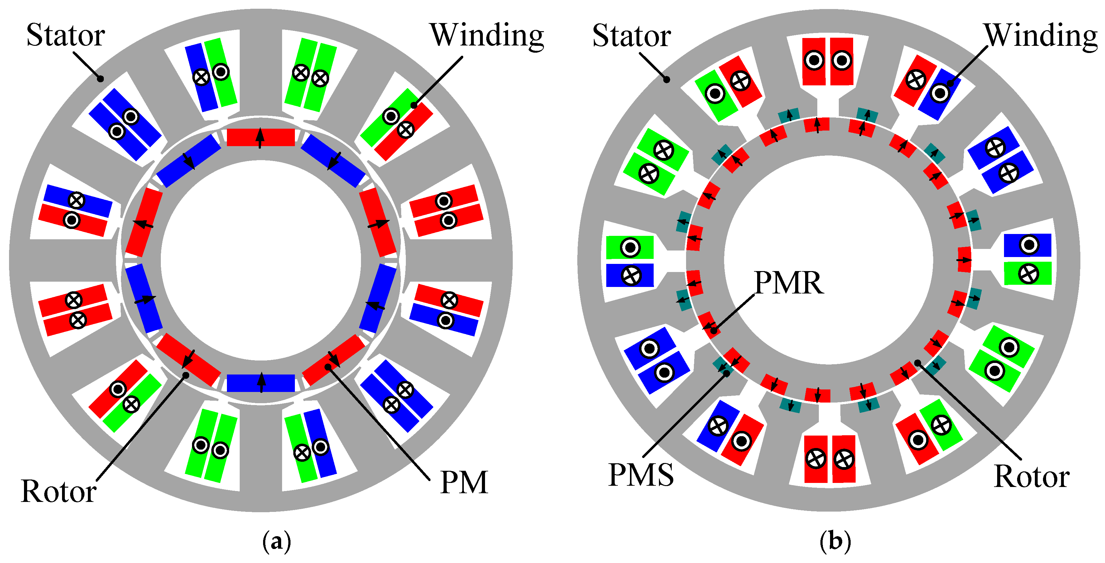
A commercial PM hub machine in [
4] for e-bike is selected as the benchmark and shown in
Figure 1a, in which the 12-slot/10-pole combination and interior PM (IPM) type are adopted. In this section, the red, green, and blue windings always correspond to phase A, phase B, and phase C, respectively. The arrows in PM always represent the direction of magnetization. For comparison, the stator slot
Q of the DPMV machine is 12 as well and adopts a split tooth structure, as shown in
Figure 1b. The number of stator modulation poles
is 24. Then, the pole pair of armature winding remains consistent with that of the commercial hub machine, e.g.,
= 5. Based on (1), the number of PMR pole pairs
should be 19. It is worth noting that both the PMR and PMS of the proposed DPMV machine adopt the CP structure. The salient rotor teeth can also serve as modulation poles, which will be elaborated in the following section.
Table 1 lists the main specifications of the two machines. They have identical volume, slot filling factor, and material. The PM weight and electromagnetic load of the proposed DPMV machine are only 75% and 87% of that of the IPM machine, respectively.
3. Torque Analyses with Multi-Working Harmonics
In this section, the PMR, PMS, and armature air-gap magnetic fields of the proposed DPMV machine are investigated independently. Their interaction and torque generation principle will be presented. Additionally, to obtain the analytical model of air-gap flux density, the derivation in this section is based on the following assumptions [
17]:
- (1)
The tangential components of the air-gap magnetic field are neglected for simplicity;
- (2)
The leakage flux is ignored; therefore, the waveform of air-gap primitive MMF is considered as square waves. In addition, the end effect is also neglected, so the air-gap MMF is regarded as the same in the axial direction;
- (3)
The permeability of stator and rotor iron is infinite, so the iron reluctance is neglected.
The general methodology of this section is as follows: Firstly, both PMR and PMS are magnetized in the North Pole direction, and the salient iron core serves as the South Pole. Therefore, the primitive air-gap PM flux density waveform within the PM range is a positive square wave, while it is a negative square wave within the core range. Similarly, the primitive armature winding flux density is the superposition of a series of square waves considering the coil polarity. Secondly, the permeance functions accounting for winding, PMS, and PMR slotting effect can be obtained by using the path of the flux lines in the corresponding opening region. The flux line always flow through a smaller reluctance path. Thirdly, the harmonic characteristics of each magnetic field are acquired by using FFT, including the spatial order, amplitude, mechanical speed, and rotation direction. Finally, the frozen permeability method is adapted to separate the torque generated due to the interaction of different magnetic fields, recognizing the contribution of each harmonics to average torque. Moreover, the torque waveforms of DPMV and counterpart IPM machines are compared using the software Ansys Electronics Desktop.
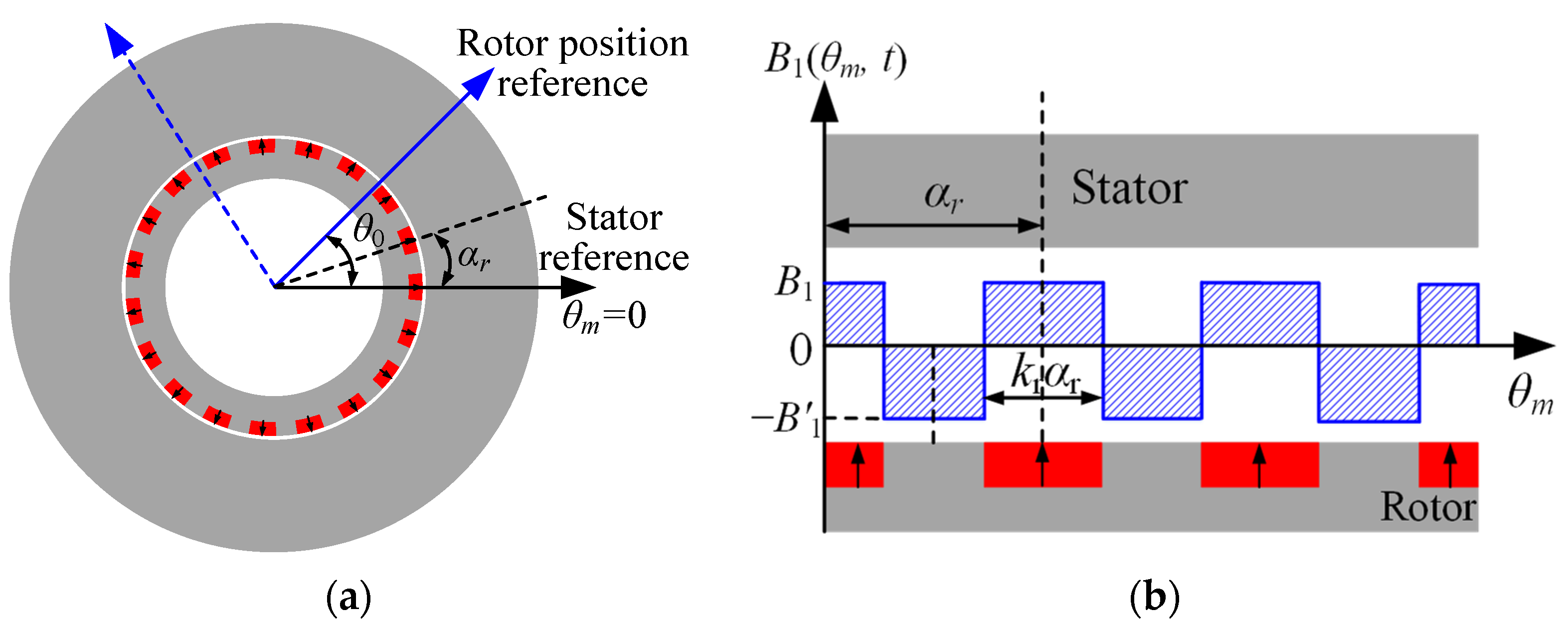
3.1. PMR Flux Density
The primitive air-gap PMR flux density without modulation by the stator is shown in
Figure 2.
and
are defined as the magnitudes of PMR and iron poles, respectively, which can be written as follows:
where
is the remanence flux density of PM, and
is the PM relative differential permeability. Further, the Fourier series expansion of the primitive PMR flux density
can be deduced as follows:
where
is the mechanical angular speed,
t is time,
is the angular position in stator reference, and
is the initial phase (
= 0 in this section).
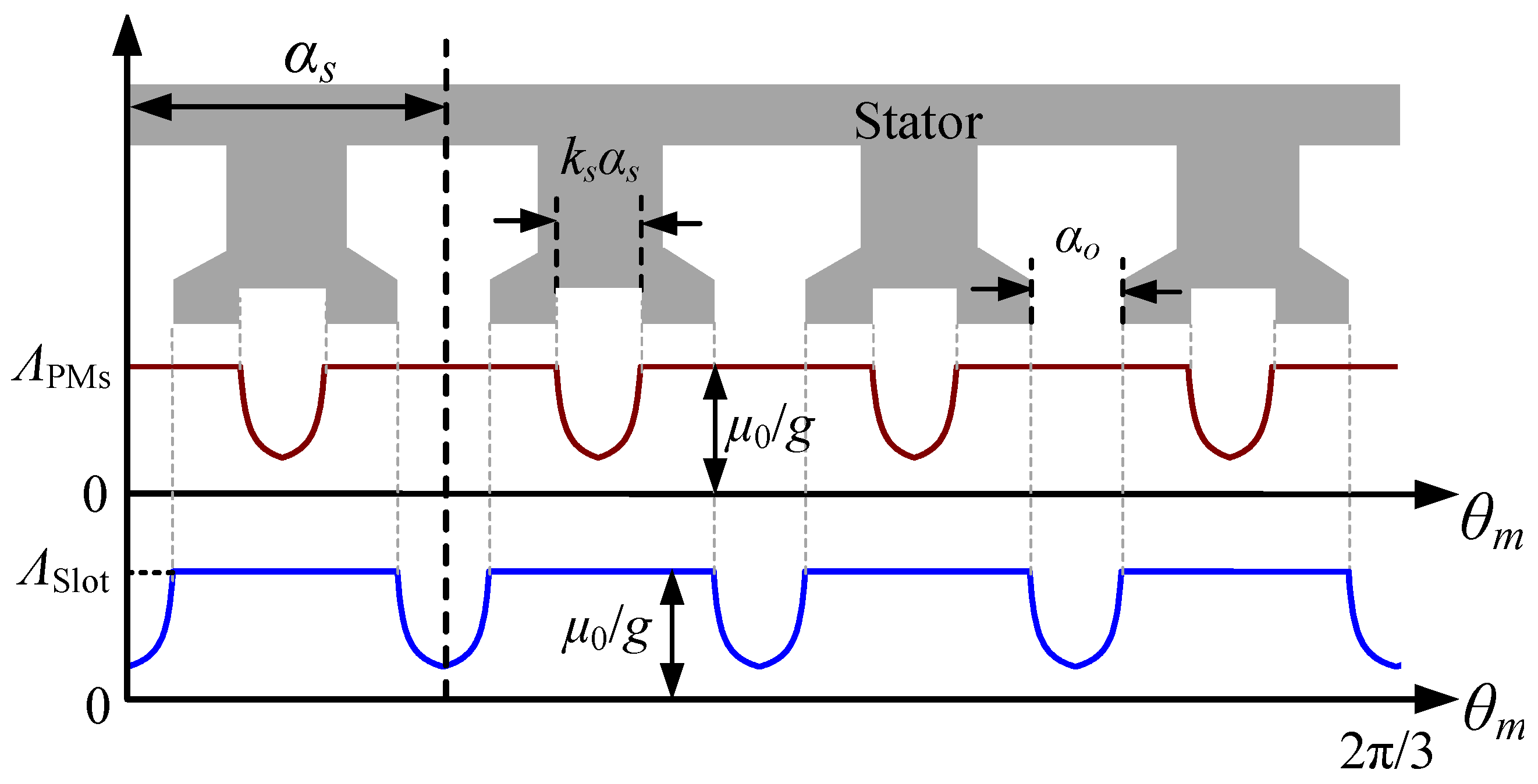
The influence of winding and PMS slots on the PMR magnetic field can be accounted by introducing a stator permeance function, as shown in
Figure 3. Here, the brownish red line represents the permeance curve caused by PMS slot, and blue line represents the permeance curve caused by winding slot. The permeance function produced by winding slot
and PMR slot
can be expressed as follows:
where
and
are Fourier coefficients of the winding slot permeance function, and
and
are Fourier factors of the PMS slot permeance function. The focus of this section is to highlight the modulation effects of topology structure on magnetic fields. Thus, the detailed expression of the above Fourier coefficients will not be discussed. Based on (5), the total stator permeance function is
where
=
Q +
, and the
and
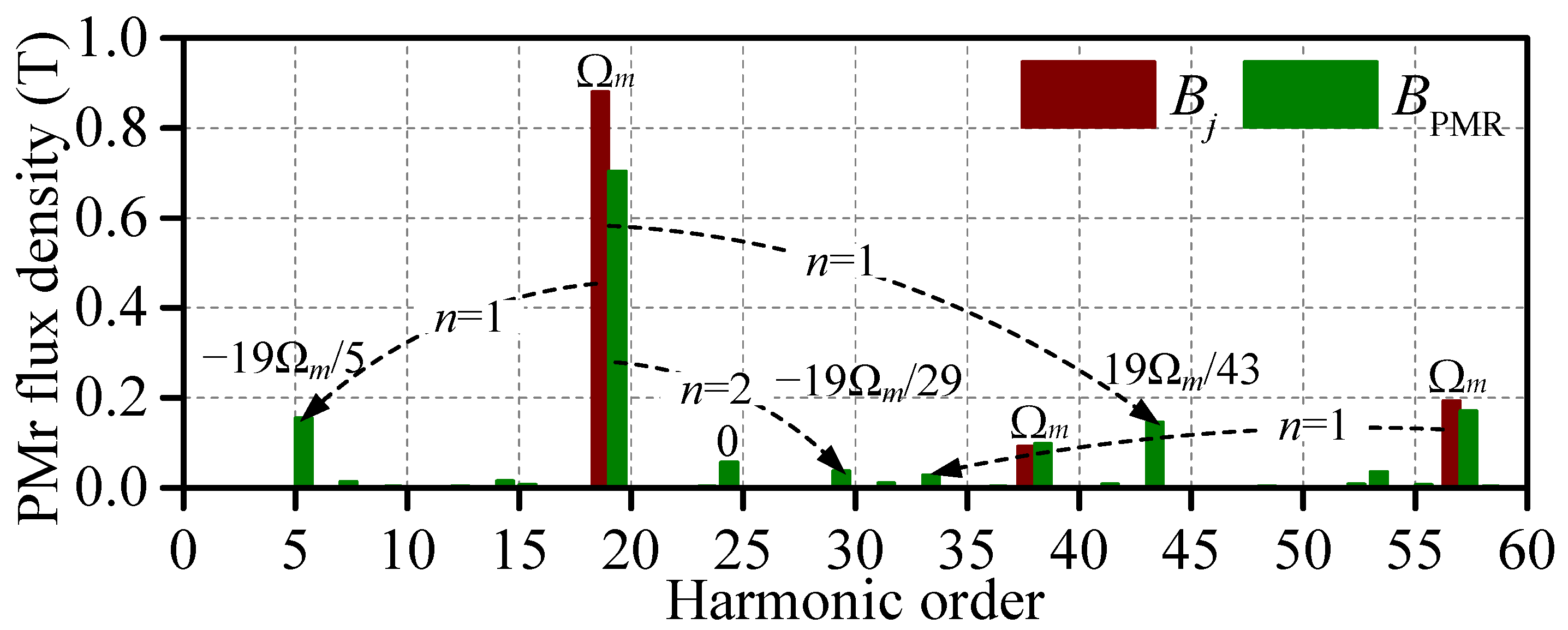
are the Fourier coefficients of the total stator permeance function. Thus, the modulated PMR air-gap flux density
can be expressed as follows:
The last two items of (7) represent the modulation effect of stator structure on the PMR magnetic field. The harmonic components with
j ±
n are generated, and the related rotation speed is
j/(
j ±
n), as shown in
Figure 4.
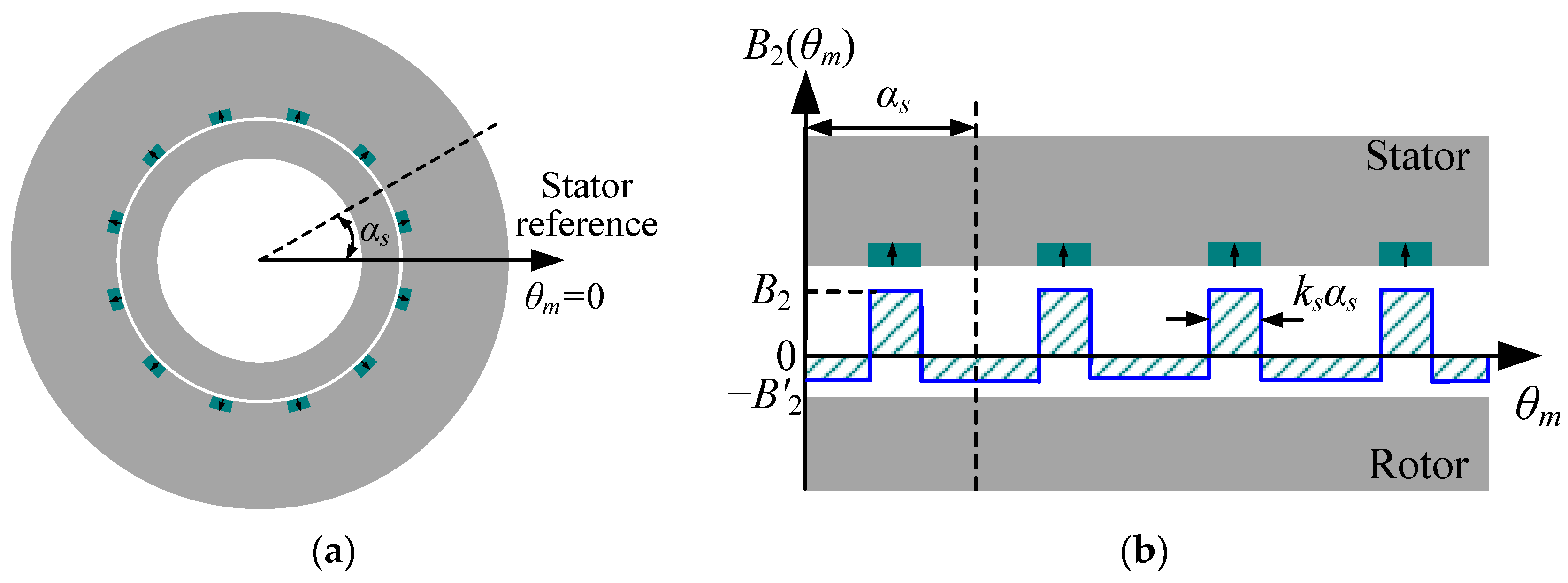
3.2. PMS Flux Density
The primitive air-gap PMS flux density
without PMR and winding slots modulation is shown in
Figure 5. The Fourier series expansion of the primitive PMS flux density can be deduced as follows:
Then, the permeance function accounting for PMR slotting effect can be written as follows:
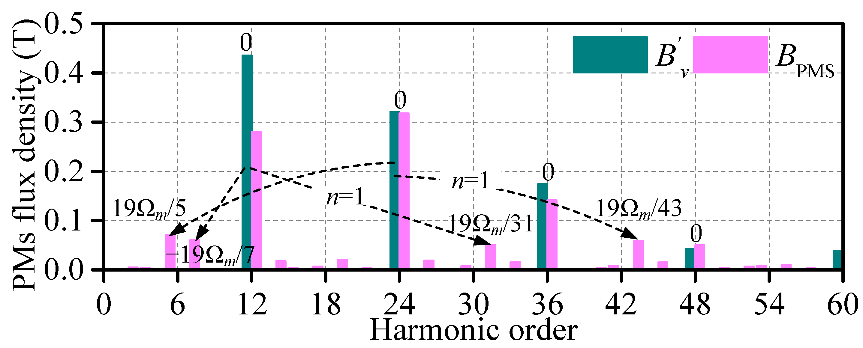
The modulated PMS air-gap flux density
can be expressed as follows:
It can be seen that the winding slot has no influence on the harmonic order of the PMS magnetic field, but only changes the harmonic amplitude. Therefore, the
is used to denote the amplitude of
vth-order harmonics after winding slot modulation. Finally, the new harmonic components with
±
are produced by the PMR slot modulation. Correspondingly, the related rotation speed is ±
/(
±
), as shown in
Figure 6.
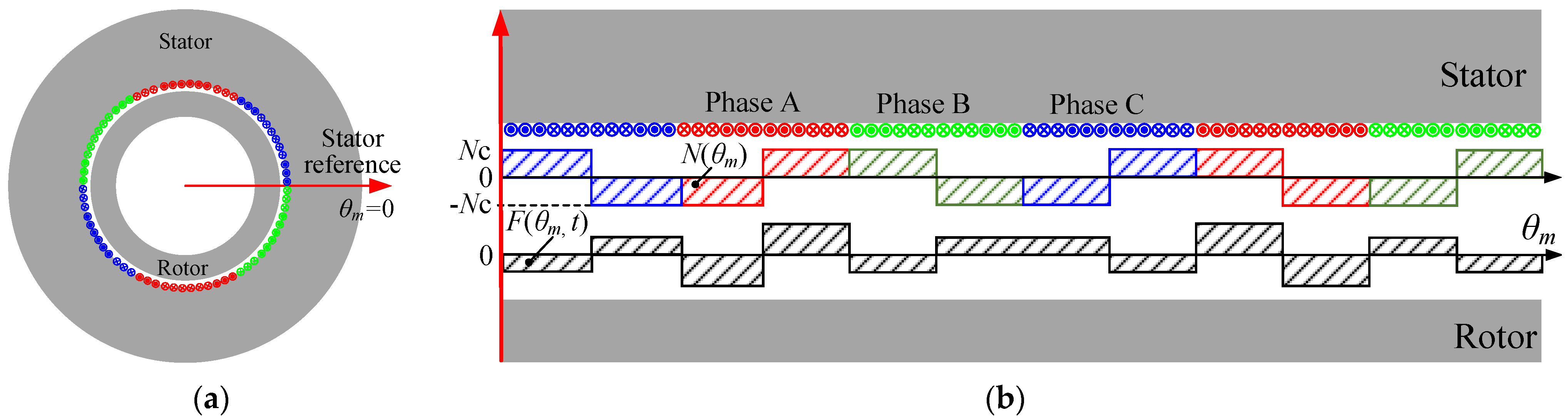
3.3. Armature Flux Density
Figure 7 shows the primitive air-gap armature MMF model and waveform, in which the initial MMF of each single phase is equivalent to an ideal square wave. Firstly, the winding function
N(
) of each phase can be expressed as follows [
23]:
where
h is the spatial harmonic order, and
is the initial angle. Based on the winding distribution shown in
Figure 7,
= −180° (
h = 1, 5, 9, 13, etc.),
= 0° (
h = 3, 7, 11, 15, etc.),
is the Fourier expansion factor, and
= 2
/
πh, and
is the winding factor of
hth-order harmonics. Then, the MMF expression is obtained by multiplying the winding function by the current, yielding the following:
l is either 0 or a positive integer.
is the amplitude of phase current. The armature air-gap flux density
considering rotor and stator modulation can be expressed as follows:
The modulation effect of winding and PMS slot on the armature magnetic field only changes the amplitude and phase, and does not result in new harmonic orders generation. The
and
represent the amplitude and phase of
hth-order harmonics after winding and PMS slots modulation, respectively. The new harmonic orders with
h ±
n emerged after rotor modulation, as shown in
Figure 8.
3.4. Torque Generation Principle
Based on the above analyses, the air-gap flux density harmonic order and corresponding mechanical speed of three magnetic fields considering bilateral modulation can be obtained, and they are presented in
Table 2. The P, N, and S represent positive, negative, and stationary rotation directions, respectively. Conventionally, the average torque is produced when the harmonic components of different magnetic fields have the same order and speed [
24]. As for the DPMV machine, there are two possible cases:
- (1)
The two magnetic fields have the same order and mechanical speed, and they can interact with each other directly and produce average torque;
- (2)
The two magnetic fields have different orders and mechanical speeds. However, there are flux modulation poles between them. The average torque can still be generated if two magnetic fields meet the following relationship:
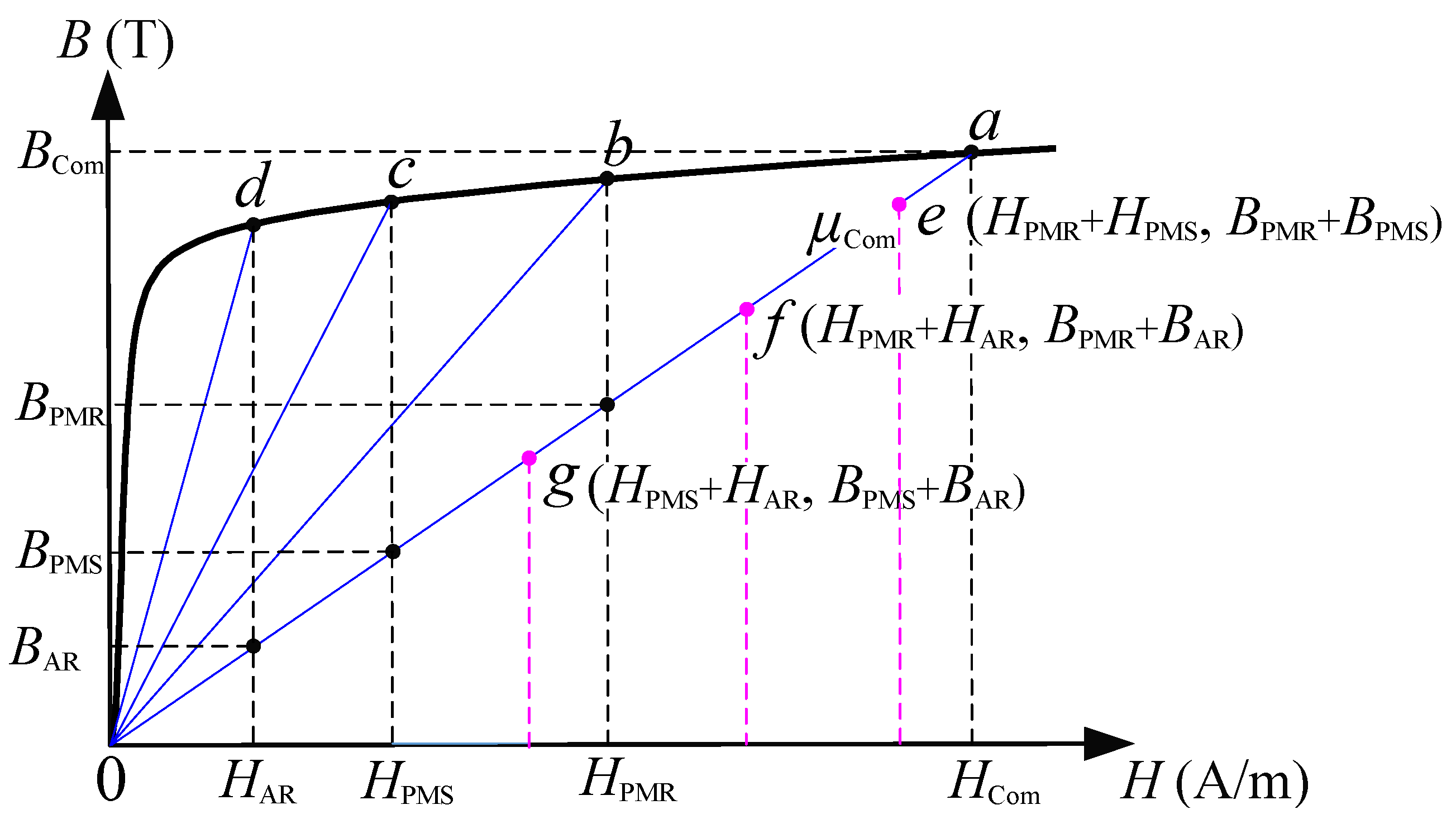
For clarity,
Figure 9 is used to describe different working points. Here, point a implies that the DPMV machine is jointly excited by three magnetic fields. Points b, c, and d indicate that the DPMV machine is only excited by PMR, PMS, and armature magnetic fields alone, respectively. There is almost no harmonic component between the PMR and PMS magnetic fields that satisfies (14) or (15), so the average torque at operating point e is approximately 0. The total average torque
of the DPMV machine is the superposition of the interaction between the PMR and armature magnetic fields, as well as the interaction between the PMS and armature magnetic fields. The contribution of each harmonic to torque can be expressed as follows:
where
r is the air-gap radius,
and
represent the air-gap radial and tangential flux densities at corresponding working points, respectively, and
k represents the harmonic order that satisfies (14) or (15).
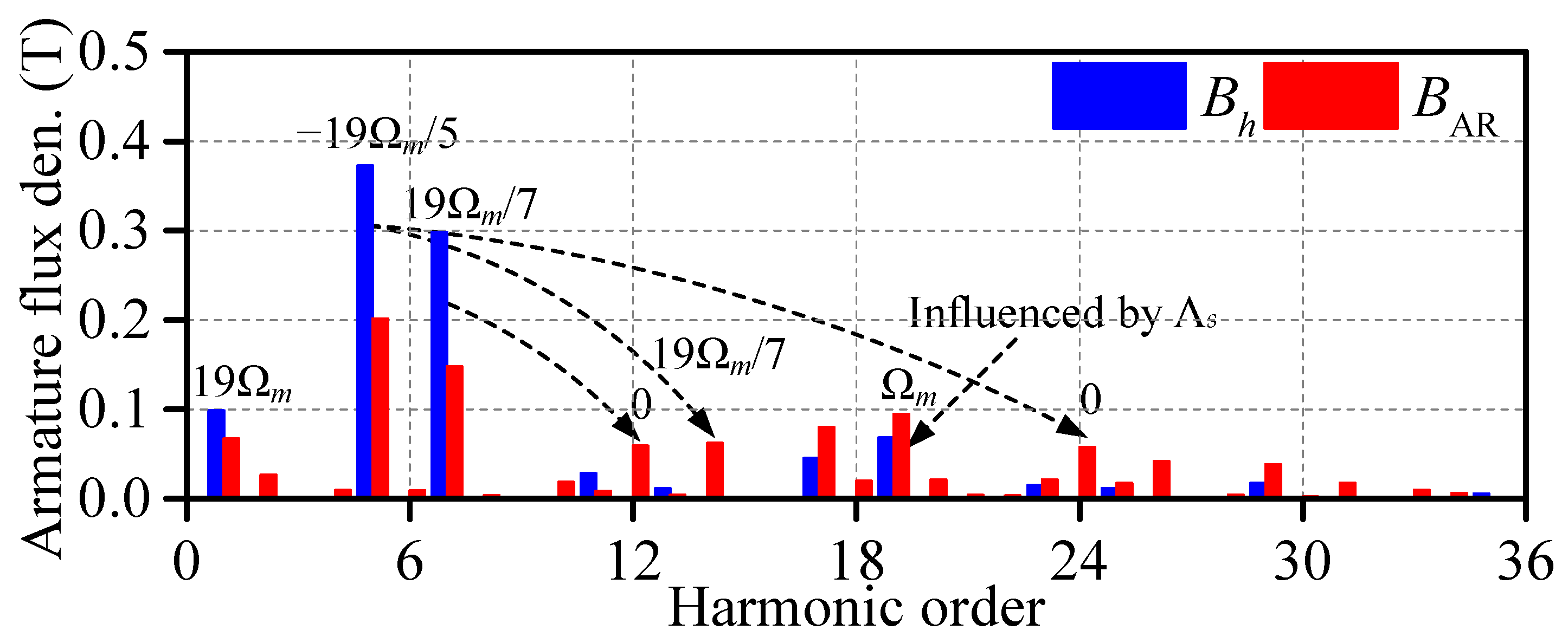
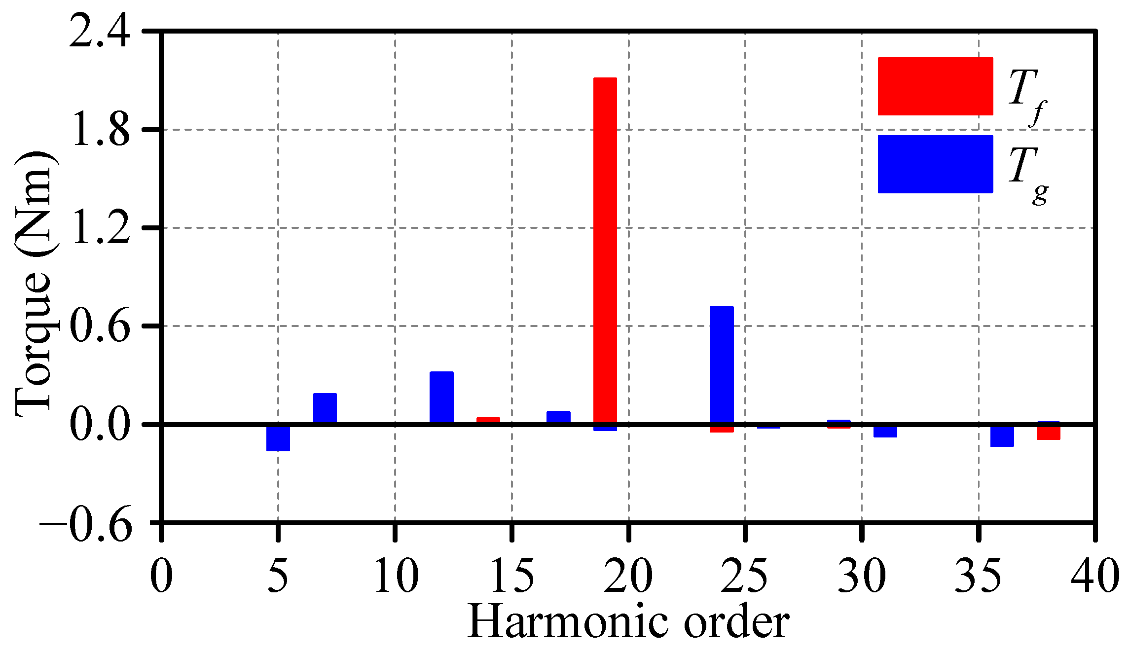
Further, the contribution of each flux density harmonics to average torque is shown in
Figure 10. It can be seen that the 19th-order harmonics of PMR and armature magnetic fields are the main source of average torque
. Similarly, the 7th-, 12th-, and 24th-order harmonics of PMS and armature magnetic fields are the main source of average torque
. By comparison, the working harmonic of commercial IPM machine is only 5th-order. This demonstrates the characteristics of multi-working harmonics in DPMV machine. Subsequently, the two torque components
and
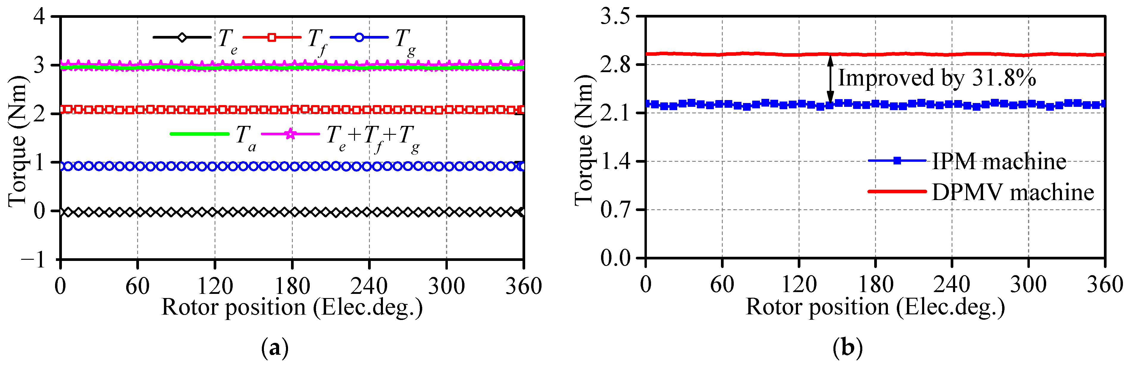
are calculated with FEM considering frozen permeability, as shown in
Figure 11a. Then, the torque waveforms of the proposed DPMV and commercial IPM machines are compared in
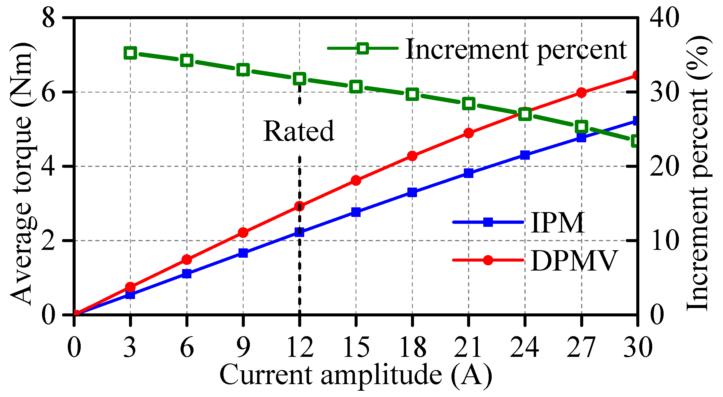
Figure 11b. The average torque values of DPMV and IPM machines are 2.2 Nm and 2.9 Nm, respectively. The average torque of the DPMV machine is improved by 31.8% compared to the IPM machine. Moreover, the DPMV machine also has a torque ripple comparable to the IPM counterpart. Additionally, the variations in average torque with current amplitude is compared in
Figure 12. Although the increment percent decreases as the current amplitude increases, the increment percent is always greater than 20% throughout the current range (0–30) A. This is mainly due to the higher harmonic components of the DPMV machine than the IPM machine. The above comparison results indicate that adopting the DPMV machine instead of the original IPM machine based on air-gap magnetic field modulation can effectively improve torque performance.
4. New Design to Improve Torque
The working harmonics of the proposed DPMV machine are identified based on the magnetic field modulation, and the 19th-order harmonic is the largest contributor. In order to further improve the average torque of the DPMV machine, two main aspects can be taken from (16). On one hand, phase angle reconfiguration makes the phase difference between the radial and tangential of the 19th-order harmonics smaller. On the other hand, the 19th-harmonic amplitude increases. Correspondingly, the Auxiliary Barrier (AB) structure and Dual Three-Phase 30° (DTP-30°) winding are adopted in this section.
The detailed results of this section are all based on the commercial finite element software Ansys Electronics Desktop, in which the 2D simulated models with different structures are established. The air-gap flux density waveform represents its radial distribution at the air-gap centerline. Then, the amplitude and phase characteristics of spatial harmonics throughout the time region can be obtained using FFT. Finally, the torque waveform and its average value of different structures are compared.
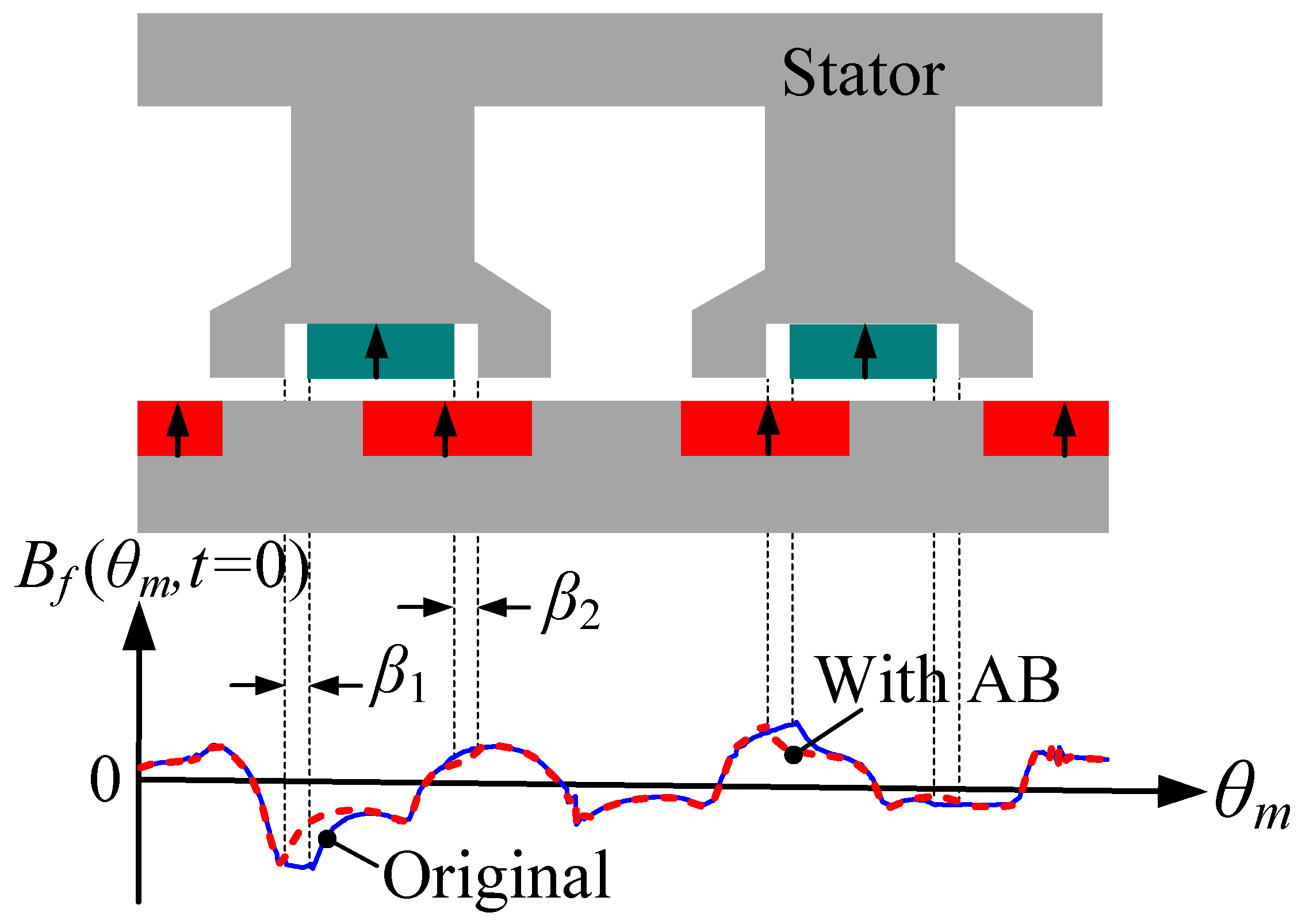
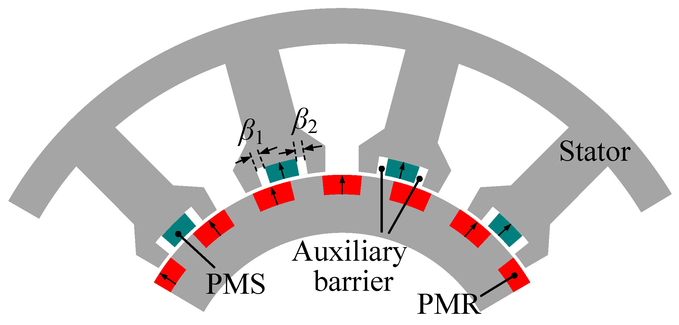
4.1. Auxiliary Barrier Structure
Figure 13 shows the 1/3 model of the new stator structure with ABr, and other dimensions consistent with the original structure. The epoxy material is used at the AB to fix the PMS. The
and
is the angle of left and right ABs, respectively. The influence of AB on the air-gap flux density at the initial rotor position is shown in
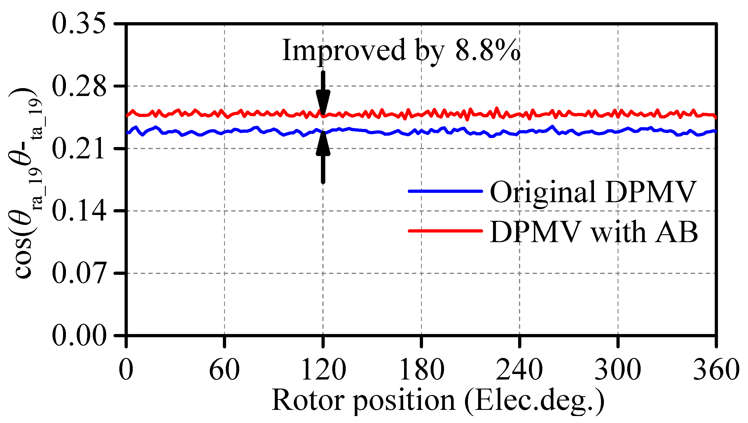
Figure 14. It can be seen that the waveform is shifted with the position of the AB. Then,
Figure 15 shows the phase difference between the radial and tangential of the 19th-order harmonic throughout the position range. The cosine value of the phase difference between the radial and tangential components of the 19th-order harmonic increases from 0.23 to 0.25, and the amplitude of 19th-order harmonic remains unchanged basically. Undoubtedly, the average torque of the DPMV machine further increases with the cosine value [
13].
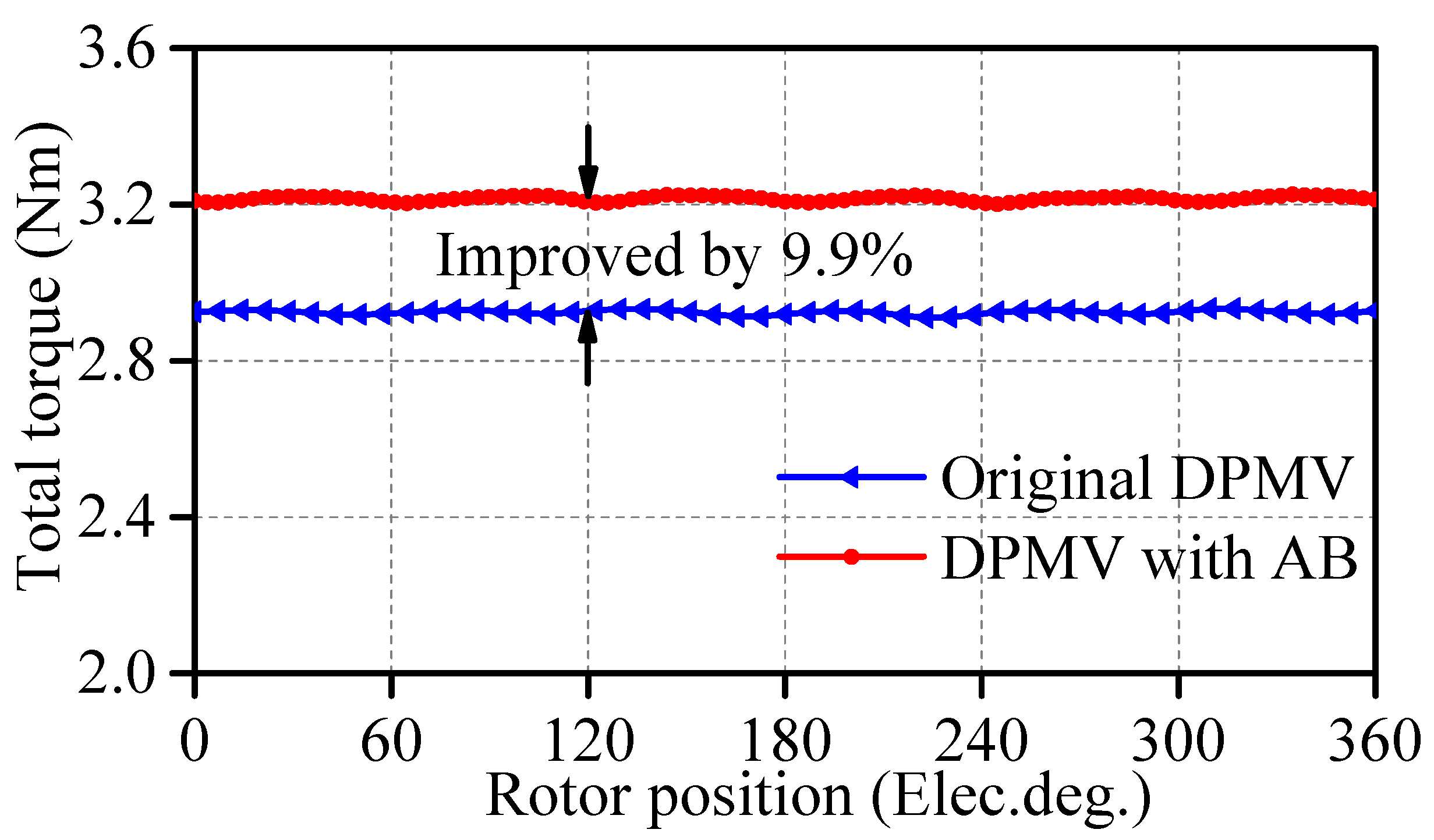
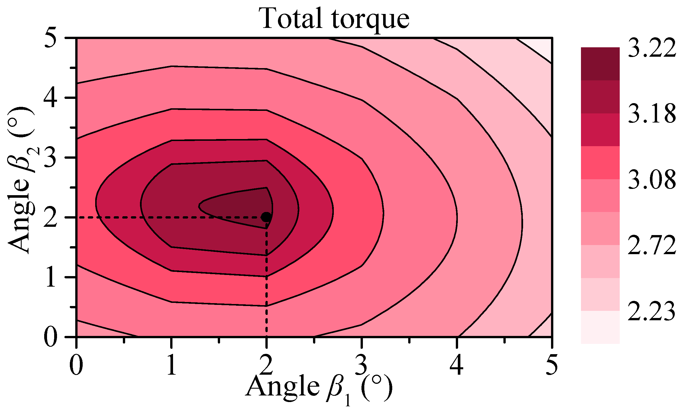
In addition, the effect of AB on average torque is also related to its dimensions.
Figure 16 describes the variation in the total torque of the DPMV machine with angles
and
. Consequently, the angles
and
both are determined to be 2°; in this case, the stator is still symmetrical. Finally, the total torque waveforms of original and new DPMV machines are compared in
Figure 17. The total torque is increased from 2.9 Nm to 3.2 Nm without deteriorating torque ripple. This indicates that the proposed new structure with AB is feasible for improving torque density.
4.2. Dual Three-Phase Winding
The DTP-30° winding configuration is conducive to increasing the winding factor and thus improving the average torque [
25]. The winding factors of 5th-, 7th-, and 19th-order winding function harmonics are all 0.933 when the DPMV machine employs the original three-phase winding. By comparison, the winding factors of the above harmonics are all 0.966 when the DTP-30° winding configuration is employed.
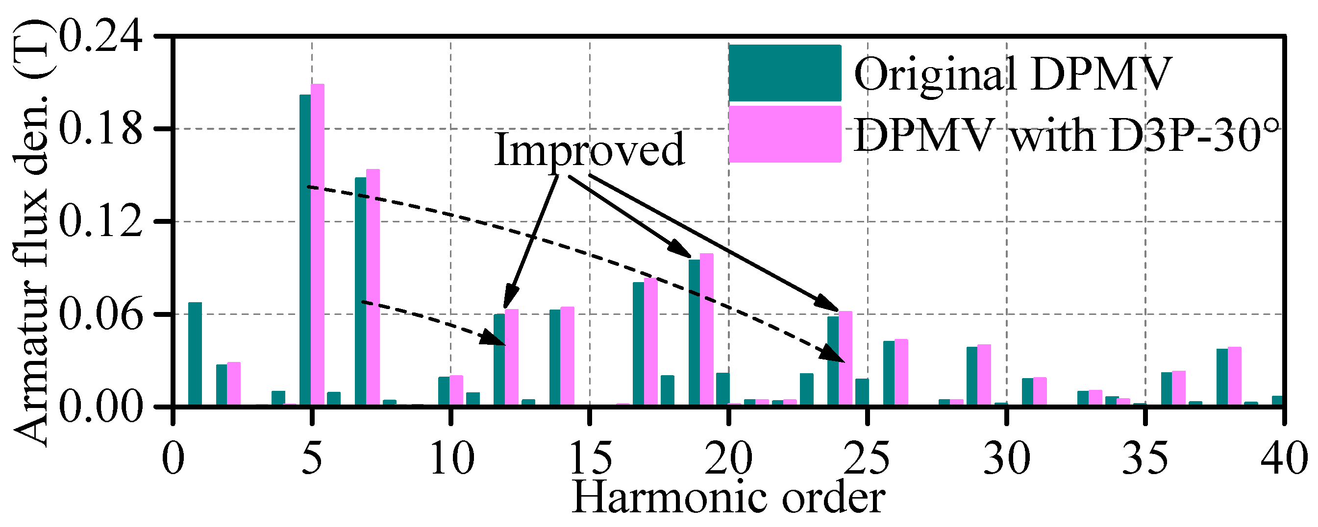
Figure 18 shows the DPMV machine with DTP-30° winding configuration, in which the ownership of winding corresponds to the color of the vector diagram. The winding configuration has no effect on the PM magnetic fields, and this section compares armature flux density with different winding configurations, as shown in
Figure 19. Based on
Figure 10, due to the increase in armature flux density of the 12th-, 19th- and 24th-order harmonics, the average torque is improved with employing DTP-30° winding.
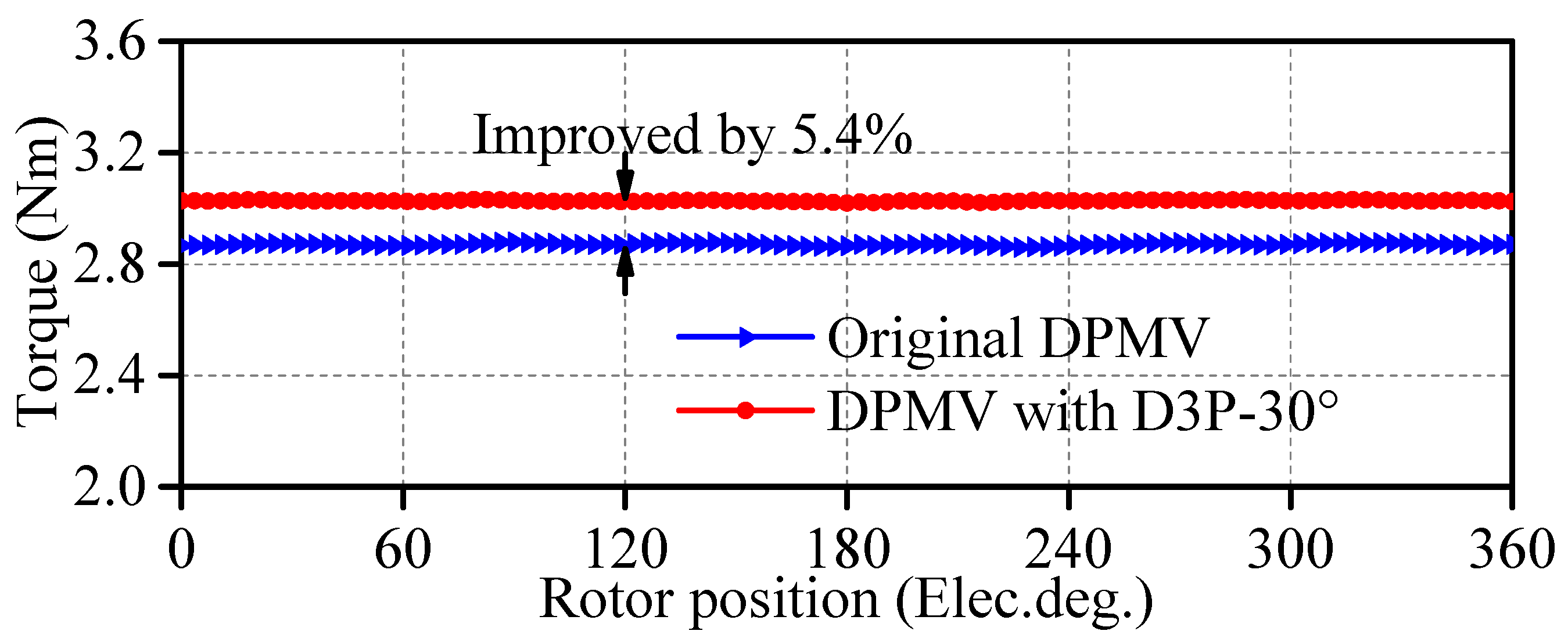
Figure 20 shows the total torque waveforms of DPMV with different winding configurations. The total torque is increased from 2.9 Nm to 3.0 Nm, and the torque ripple is superior as well. It should be pointed out that adopting the DTP-30° configuration results in complex control topology and increased control difficulty.
5. Conclusions
This paper focuses on the torque analysis and improved design of the DPMV machine with the air-gap field modulation principle. The MMF permeance models of PMR, PMS, and armature magnetic fields have been established, and the modulation effect of topology structure has been analyzed in detail. Afterward, the torque generation mechanism of the DPMV machine has been investigated and the contribution of effective working harmonics to average torque has been identified with the frozen permeability method. The results show that the 7th-, 12th-, 19th- and 24th-order flux density harmonics are the main source of average torque, and especially the contribution of 19th-order harmonic exceeds 65%. Thanks to the multi-working harmonic characteristic, the proposed DPMV machine improves average torque by 31.8% with 75% PM weight of the IPM counterpart. The main contribution of this paper lies in proposing the auxiliary barrier structure and dual three-phase winding to improve the contribution of 19th-order harmonic to the average torque, respectively. While the auxiliary barrier structure is beneficial for increasing the angle difference between the radial and tangential components of the 19th-order harmonic, the dual three-phase winding can improve the amplitude of the 19th-order harmonic.
This paper solely focuses on the qualitative analyses of the torque generation mechanism of the DPMV machine. Therefore, the leakage flux, end effect, and iron reluctance are neglected. Future work will focus on the quantitative calculation of steady torque and torque ripple considering the nonlinear characteristics, and manufacturing a prototype for validation.
Author Contributions
Conceptualization, N.B. and Y.S.; methodology, W.Z. and J.J.; software, Y.S.; validation, J.J.; formal analysis, N.B., W.Z. and Y.S.; writing—original draft preparation, Y.S.; writing—review and editing, N.B. and W.Z.; visualization, N.B. and Y.S.; supervision, N.B. and W.Z.; project administration, N.B.; funding acquisition, N.B. All authors have read and agreed to the published version of the manuscript.
Funding
This research received no external funding.
Data Availability Statement
Not applicable.
Conflicts of Interest
The authors declare no conflict of interest.
References
- Snoussi, J.; Elghali, S.B.; Benbouzid, M.; Mimouni, M.F. Optimal sizing of energy storage systems using frequency-separation-based energy management for fuel cell hybrid electric vehicles. IEEE Trans. Veh. Technol. 2018, 67, 9337–9346. [Google Scholar] [CrossRef]
- Capata, R.; Calabria, A. High-performance electric/hybrid vehicle—Environmental, economic and technical assessments of electrical accumulators for sustainable mobility. Energies 2022, 15, 2134. [Google Scholar] [CrossRef]
- Nasiri-Zarandi, R.; Karami-Shahnani, A.; Toulabi, M.S.; Tessarolo, A. Design and experimental performance assessment of an outer rotor PM-assisted SynRM for the electric bike propulsion. IEEE Trans. Transport. Electrific. 2023, 9, 727–736. [Google Scholar] [CrossRef]
- Contò, C.; Bianchi, N. E-bike motor drive: A review of configurations and capabilities. Energies 2023, 16, 160. [Google Scholar] [CrossRef]
- Asef, P.; Bargallo, R.; Lapthorn, A.; Tavernini, D.; Shao, L.; Sorniotti, A. Assessment of the energy consumption and drivability performance of an IPMSM-driven electric vehicle using different buried magnet arrangements. Energies 2021, 14, 1418. [Google Scholar] [CrossRef]
- Abdelkefi, A.; Souissi, A.; Abdennadher, I.; Masmoudi, A. On the analysis and torque enhancement of flux-switching permanent magnet machines in electric power steering systems. World Electr. Veh. J. 2022, 13, 64. [Google Scholar] [CrossRef]
- Fatemi, A.; Nehl, T.W.; Yang, X.; Hao, L.; Gopalakrishnan, S.; Omekanda, A.M.; Namuduri, C.S. Design optimization of an electric machine for a 48-V hybrid vehicle with comparison of rotor technologies and pole-slot combinations. IEEE Trans. Ind. Appl. 2020, 56, 4609–4622. [Google Scholar] [CrossRef]
- Gu, Z.; Wang, K.; Zhu, Z.Q.; Wu, Z.; Liu, C.; Cao, R. Torque improvement in five-phase unequal tooth SPM machine by injecting third harmonic current. IEEE Trans. Veh. Technol. 2018, 67, 206–215. [Google Scholar] [CrossRef]
- Lee, M.; Koo, B.; Nam, K. Analytic optimization of the Halbach array slotless motor considering stator yoke saturation. IEEE Trans. Magn. 2021, 57, 8200806. [Google Scholar] [CrossRef]
- Zeng, X.; Quan, L.; Zhu, X.; Xu, L.; Liu, F. Investigation of an asymmetrical rotor hybrid permanent magnet motor for approaching maximum output torque. IEEE Trans. Appl. Supercond. 2019, 29, 0602704. [Google Scholar] [CrossRef]
- Sun, Y.; Zhao, W.; Ji, J.; Zheng, J.; Cheng, Y. Torque improvement in dual m-phase permanent-magnet machines by phase shift for electric ship applications. IEEE Trans. Veh. Technol. 2020, 69, 9601–9612. [Google Scholar] [CrossRef]
- Cheng, M.; Han, P.; Hua, W. General airgap field modulation theory for electrical machines. IEEE Trans. Ind. Electron. 2017, 64, 6063–6074. [Google Scholar] [CrossRef]
- Tahanian, H.; Aliahmadi, M.; Faiz, J. Ferrite permanent magnets in electrical machines: Opportunities and challenges of a non-rare-earth alternative. IEEE Trans. Magn. 2020, 56, 900120. [Google Scholar] [CrossRef]
- Guendouz, W.; Tounzi, A.; Rekioua, T. Design of quasi-halbach permanent-magnet vernier machine for direct-drive urban vehicle application. Machines 2023, 11, 136. [Google Scholar] [CrossRef]
- Akuru, U.B.; Ullah, W.; Idoko, H.C.; Khan, F. Comparative performance evaluation and prototyping of double-stator wound-field flux modulation machines. In Proceedings of the 2022 International Conference on Electrical Machines (ICEM), Valencia, Spain, 5–8 September 2022; pp. 1893–1898. [Google Scholar]
- Alavijeh, M.M.; Mirsalim, M. Design and optimization of a new dual-rotor Vernier machine for wind-turbine application. In Proceedings of the 2020 28th Iranian Conference on Electrical Engineering (ICEE), Tabriz, Iran, 4–6 August 2020; pp. 1–6. [Google Scholar]
- Shi, Y.; Zhong, J.; Jian, L. Quantitative analysis of back-EMF of a dual-permanent-magnet-excited machine: Alert to flux density harmonics which make a negative contribution to back-EMF. IEEE Access 2021, 9, 94064–94077. [Google Scholar] [CrossRef]
- Jang, D.; Chang, J. Investigation of doubly salient structure for permanent magnet vernier machines using flux modulation effects. IEEE Trans. Energy Convers. 2019, 34, 2019–2028. [Google Scholar] [CrossRef]
- Jian, L.; Shi, Y.; Ching, T.W. Quantitative comparison of two typical field-modulated permanent magnet machines: Unidirectional field modulation effect versus bidirectional field modulation effect. In Proceedings of the 2019 22nd International Conference on Electrical Machines and Systems (ICEMS), Harbin, China, 11–14 August 2019; pp. 1–6. [Google Scholar]
- Qi, J.; Zhu, Z.Q.; Yan, L.; Jewell, G.W.; Gan, C.; Ren, Y.; Brockway, S.; Hilton, C. Effect of pole shaping on torque characteristics of consequent pole PM machines. IEEE Trans. Ind. Appl. 2022, 58, 3511–3521. [Google Scholar] [CrossRef]
- Li, J.; Wang, K. A novel spoke-type PM machine employing asymmetric modular consequent-pole rotor. IEEE/ASME Trans. Mechatronics 2019, 24, 2182–2192. [Google Scholar] [CrossRef]
- Wang, K.; Li, J.; Zhu, S.; Liu, C. Novel hybrid-pole rotors for consequent-pole PM machines without unipolar leakage flux. IEEE Trans. Ind. Electron. 2019, 66, 6811–6823. [Google Scholar] [CrossRef]
- Sun, Y.; Zhao, W.; Ji, J.; Zheng, J.; Song, X. Effect of phase shift on inductance and short-circuit current in dual three-phase 48-slot/22-pole permanent-magnet machines. IEEE Trans. Ind. Electron. 2022, 69, 1135–1145. [Google Scholar] [CrossRef]
- Zhu, Z.Q.; Liu, Y. Analysis of air-gap field modulation and magnetic gearing effect in fractional-slot concentrated-winding permanent-magnet synchronous machines. IEEE Trans. Ind. Electron. 2018, 65, 3688–3698. [Google Scholar] [CrossRef]
- Li, Y.; Zhu, Z.Q.; Wu, X.; Thomas, A.S.; Wu, Z. Comparative study of modular dual 3-phase permanent magnet machines with overlapping/non-overlapping windings. IEEE Trans. Ind. Appl. 2019, 55, 3566–3576. [Google Scholar] [CrossRef]
Figure 1.
Cross-section of the PM machine: (a) commercial IPM machine; (b) DPMV machine.
Figure 1.
Cross-section of the PM machine: (a) commercial IPM machine; (b) DPMV machine.
Figure 2.
Air-gap PMR flux density without stator modulation. (a) Model. (b) Waveform (θ0 = 0, t = 0).
Figure 2.
Air-gap PMR flux density without stator modulation. (a) Model. (b) Waveform (θ0 = 0, t = 0).
Figure 3.
Air-gap permeance function accounting for winding and PMS slotting effect.
Figure 3.
Air-gap permeance function accounting for winding and PMS slotting effect.
Figure 4.
Spectrum comparison of PMR flux density before and after stator modulation by FEM.
Figure 4.
Spectrum comparison of PMR flux density before and after stator modulation by FEM.
Figure 5.
Air-gap PMS flux density without winding and PMR slots modulation. (a) Model. (b) Waveform.
Figure 5.
Air-gap PMS flux density without winding and PMR slots modulation. (a) Model. (b) Waveform.
Figure 6.
Spectrum comparison of PMS flux density before and after rotor modulation via FEM.
Figure 6.
Spectrum comparison of PMS flux density before and after rotor modulation via FEM.
Figure 7.
Air-gap armature MMF without winding, PMS, and PMR slots modulation. (a) Model. (b) Waveform (t = 0).
Figure 7.
Air-gap armature MMF without winding, PMS, and PMR slots modulation. (a) Model. (b) Waveform (t = 0).
Figure 8.
Spectrum comparison of PMS flux density before and after rotor modulation via FEM.
Figure 8.
Spectrum comparison of PMS flux density before and after rotor modulation via FEM.
Figure 9.
Different working points are represented by B-H curve.
Figure 9.
Different working points are represented by B-H curve.
Figure 10.
The contribution of each flux density harmonic to average torque.
Figure 10.
The contribution of each flux density harmonic to average torque.
Figure 11.
Torque waveforms. (a) Torque separation of DPMV machine. (b) Torque comparison between IPM and DPMV machines.
Figure 11.
Torque waveforms. (a) Torque separation of DPMV machine. (b) Torque comparison between IPM and DPMV machines.
Figure 12.
The variations in average torque with current amplitude.
Figure 12.
The variations in average torque with current amplitude.
Figure 13.
Schematic diagram of the stator with AB.
Figure 13.
Schematic diagram of the stator with AB.
Figure 14.
Influence of AB on the air-gap flux density at working point f.
Figure 14.
Influence of AB on the air-gap flux density at working point f.
Figure 15.
The cosine value of phase difference between radial and tangential components.
Figure 15.
The cosine value of phase difference between radial and tangential components.
Figure 16.
Total torque variation in the DPMV machine with angles and .
Figure 16.
Total torque variation in the DPMV machine with angles and .
Figure 17.
Total torque waveform comparison of the DPMV with and without AB.
Figure 17.
Total torque waveform comparison of the DPMV with and without AB.
Figure 18.
The DPMV with DTP-30° winding configuration.
Figure 18.
The DPMV with DTP-30° winding configuration.
Figure 19.
Spectrum comparison of armature flux density of the DPMV with different winding configurations at point d.
Figure 19.
Spectrum comparison of armature flux density of the DPMV with different winding configurations at point d.
Figure 20.
Total torque waveform comparison of the DPMV with different winding configurations.
Figure 20.
Total torque waveform comparison of the DPMV with different winding configurations.
Table 1.
Main parameters of the IPM and DPMV machines.
Table 1.
Main parameters of the IPM and DPMV machines.
| Items | Symbol | IPM | DPMV |
|---|
| Pole number of PMR | | 10 | 19 |
| Pole number of PMS | | / | 12 |
| Number of stator slot | Q | 12 | 12 |
| Stator outer diameter (mm) | | 90 | 90 |
| Stator inner diameter (mm) | | 52 | 52 |
| Axial length (mm) | | 30 | 30 |
| Air-gap length (mm) | g | 0.5 | 0.5 |
| Stator slot area (mm2) | | 154 | 137 |
| Turn number per coil | | 23 | 20 |
| Thickness of PMR (mm) | | 3 | 2.2 |
| Thickness of PMS (mm) | | / | 2 |
| Pole-arc ratio of PMR | | 0.81 | 0.54 |
| Pole-arc ratio of PMS | | / | 0.27 |
| Total PM weight (g) | / | 81 | 61 |
| PM material | / | N40UH | N40UH |
Table 2.
Air-gap flux density harmonics of different magnetic fields.
Table 2.
Air-gap flux density harmonics of different magnetic fields.
| | Harmonic Order | Mechanical Speed | Rotate Direction |
|---|
| PMR magnetic field | | | P |
| + | /( + ) | P |
| − | /( − ) | ( − > 0) P
( − < 0) N |
| PMS magnetic field | v | 0 | S |
| v + n | n/(v + n) | P |
| v − n | −n/(v − n) | (v − n > 0) N
(v − n < 0) P |
Armature
magnetic field
(h = 6l − 1) | h | −/h | N |
| h + n | −(1 − n)/(h + n) | n ≠ 1 P
n = 1 S |
| h − n | −(1 + n)/(h − n) | (h − n > 0) N
(h − n < 0) P |
Armature
magnetic field
(h = 6l + 1) | h | −/h | P |
| h + n | (1 + n)/(h + n) | P |
| h − n | (1 − n)/(h − n) | (h − n > 0|n ≠ 1) N
n = 1 S
(h − n < 0|n ≠ 1) P |
| Disclaimer/Publisher’s Note: The statements, opinions and data contained in all publications are solely those of the individual author(s) and contributor(s) and not of MDPI and/or the editor(s). MDPI and/or the editor(s) disclaim responsibility for any injury to people or property resulting from any ideas, methods, instructions or products referred to in the content. |
© 2023 by the authors. Licensee MDPI, Basel, Switzerland. This article is an open access article distributed under the terms and conditions of the Creative Commons Attribution (CC BY) license (https://creativecommons.org/licenses/by/4.0/).


