1. Introduction
The effort to reverse the current climate crisis goes through the decarbonization of electric power systems. Electricity production is the major greenhouse gas-emitting activity only second to transportation and, as the world is accelerating the transition to net zero, is shifting from fossil fuel to renewable sources. According to the International Energy Agency (IEA), in the half-decade from 2022 to 2027, the global renewable energy capacity additions will be as much as that witnessed in the previous two decades (2001–2021) and, in 2027, the global photovoltaic (PV) installed capacity will surpass that of coal [
1].
Energy production from PV systems is optimal when temperature and solar irradiation are uniform across all PV modules, but these ideal conditions are often difficult to meet in practice [
2]. Traditionally, PV modules are series-connected in strings, whose terminals are connected to a power electronic interface [
3,
4,
5]. A well-known issue of this configuration is the power loss due to mismatch between series-connected PV modules in a string. In case of non-uniform irradiation between PV modules in the same string, by-pass diodes clamp the output voltage of shaded PV modules, which therefore provide no power output. While this action saves the shaded modules from the detrimental consequences of hot-spot [
6], it removes any energy harvest from PV modules which are not fully irradiated. This mismatching issue is handled efficiently by using PV module integrated electronics [
7], such as dc-dc module integrated converters (micro-converters), or dc-ac module integrated converters (micro-inverters) [
8]. These PV module-level architectures are known as distributed maximum power point tracking (MPPT) PV systems [
9,
10]. For micro-converters, which are of interest to this work, [
11] estimated that they can increase the yearly energy yield of a PV system up to 6%, recovering, on average, 36% of the power otherwise lost from partial shading. Other works have investigated the energy production improvement of PV power systems based on micro-inverters, with [
12] finding that a two-stage solar micro-inverter increased energy production close to 2% in one day, resulting in a reduction in annual energy losses between 22.3% and 26%. A highly efficient micro-inverter topology using LLC resonant converter is studied in [
13]; however, dedicated studies are required to assess its energy recovery potential over time.
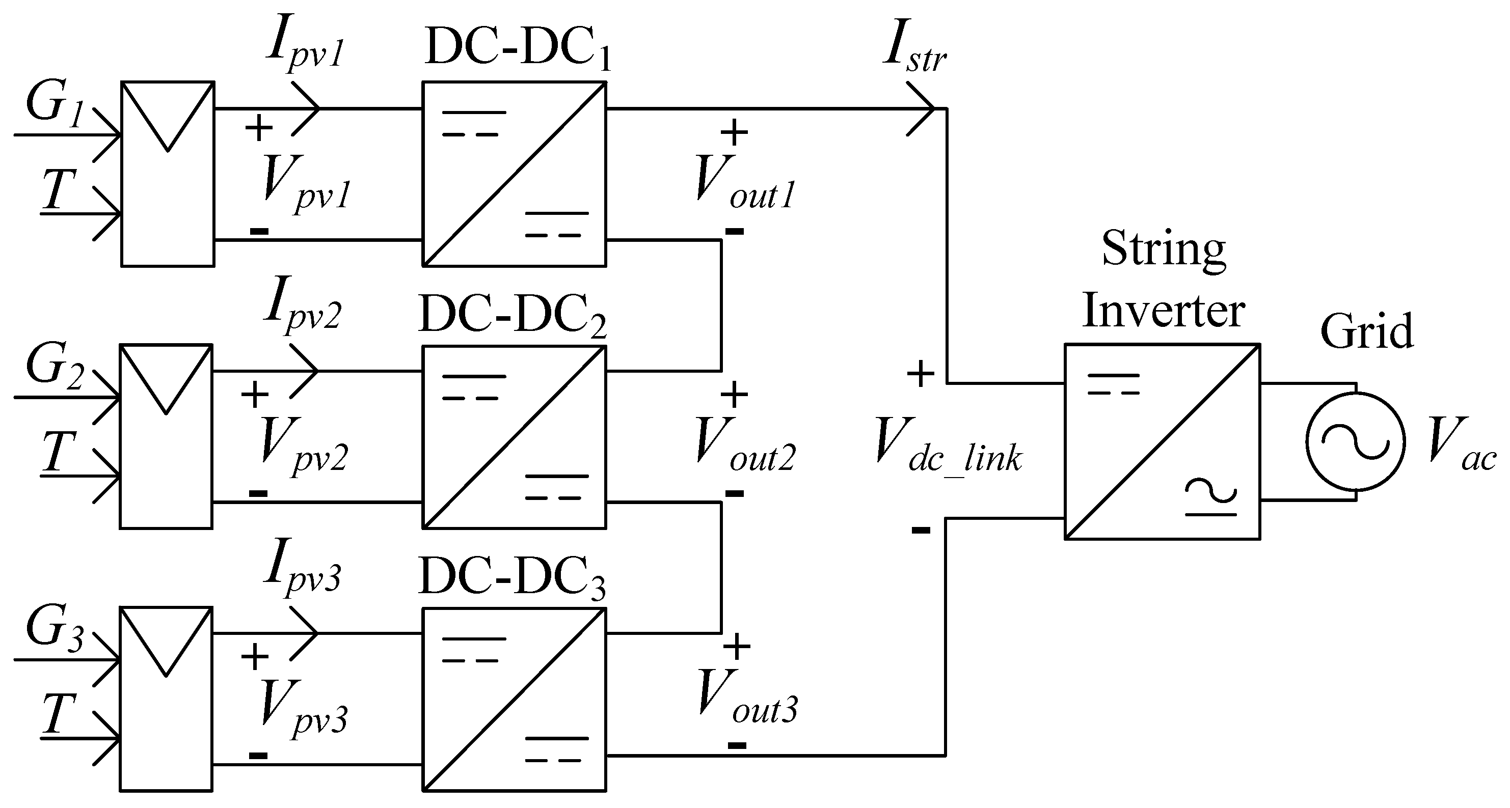
The series-connected micro-converter solution in
Figure 1 is a promising candidate for high-efficiency and low-cost distributed MPPT PV systems [
14]. It finds proficient application especially when some of the PV modules are going to be shaded during part of the day, e.g., in residential settings, by trees, chimneys, and so on.
Each micro-converter features independent control of the input voltage on the PV side, to track the MPP of the associated module, regardless of the irradiation being uniform on all PV modules. The string current
, entering the inverter and common to all micro-converter outputs, is determined by the power delivered by every micro-converter and by the dc-link voltage. Neglecting micro-converter power losses for simplicity, then the power produced by a PV module
is also the power at the output of its micro-converter, and
while the output voltage of a micro-converter
can be expressed as the ratio between its output power and its output current, that is [
15]
According to this expression, the output voltage of a micro-converter is a fraction of the dc-link voltage and varies according to the ratio of the PV power processed by the micro-converter of interest and all the micro-converters in the system.
Controlling a series-connected micro-converter can be a challenge, especially during system start-up, when the common dc-link voltage needs to be formed and increased sufficiently above the peak ac voltage, for the inverter to transfer power to the grid. Unless tailored communication-free start-up procedures and protection functions are applied, this process would require an additional communication link between the micro-converter and the grid-tied inverter [
14,
16], resulting in extra costs and complexity. Drawing on the work of [
17], this paper proposes an enhanced control strategy to safely start-up a grid-tied PV system with series-connected micro-converters. The proposed start-up procedure has several advantages. Firstly, it is simple to implement, requiring minimal computational burden; unlike the solution from [
18], it works without the need for an additional output voltage control loop in each micro-converter. Secondly, and conversely to [
14], it does not use a current sensor at the dc-link input of the inverter and at each micro-converter output. Thirdly, it features enhanced safety, as micro-converters will transfer power to the dc-link only if the grid is present, contrarily to [
16], wherein it is proposed to form the dc-link voltage at the start-up using the micro-converters, rather than the rectified grid voltage. Compared with [
17], the mechanics of the control algorithm proposed to smoothly start-up the micro-converters are here described more extensively so that such control can be easily reproduced and adopted by the interested community of practice. Furthermore: the literature review is broadened and includes more relevant and recent resources; the key principle driving the dc-link voltage partitioning among micro-converter outputs is recalled; the interpretation of results is extended and complemented by a new discussion section; the conclusions feature more meaningful directions for future work. The safe and smooth start-up of grid-connected solar systems with PV module integrated micro-converters is a topic of fundamental importance, but so far is seldom discussed in the literature. While [
17] stimulates attention towards the problem, this paper aims to be a more well-rounded reference.
The rest of this manuscript is organized as follows. In
Section 2, the working principle of the elements in
Figure 1 is reviewed.
Section 3 describes the proposed system start-up procedure, with emphasis on the micro-converter control.
Section 4 discusses the PLECS simulation results from the proposed system start-up procedure; including observations on the system behavior under varying irradiance conditions.
Section 5 provides a further reflection on the results obtained, while highlighting differences with similar existing studies. Finally,
Section 6 summarizes the main achievements and concludes the manuscript.
2. The Series-Connected Micro-Converter Working Principle
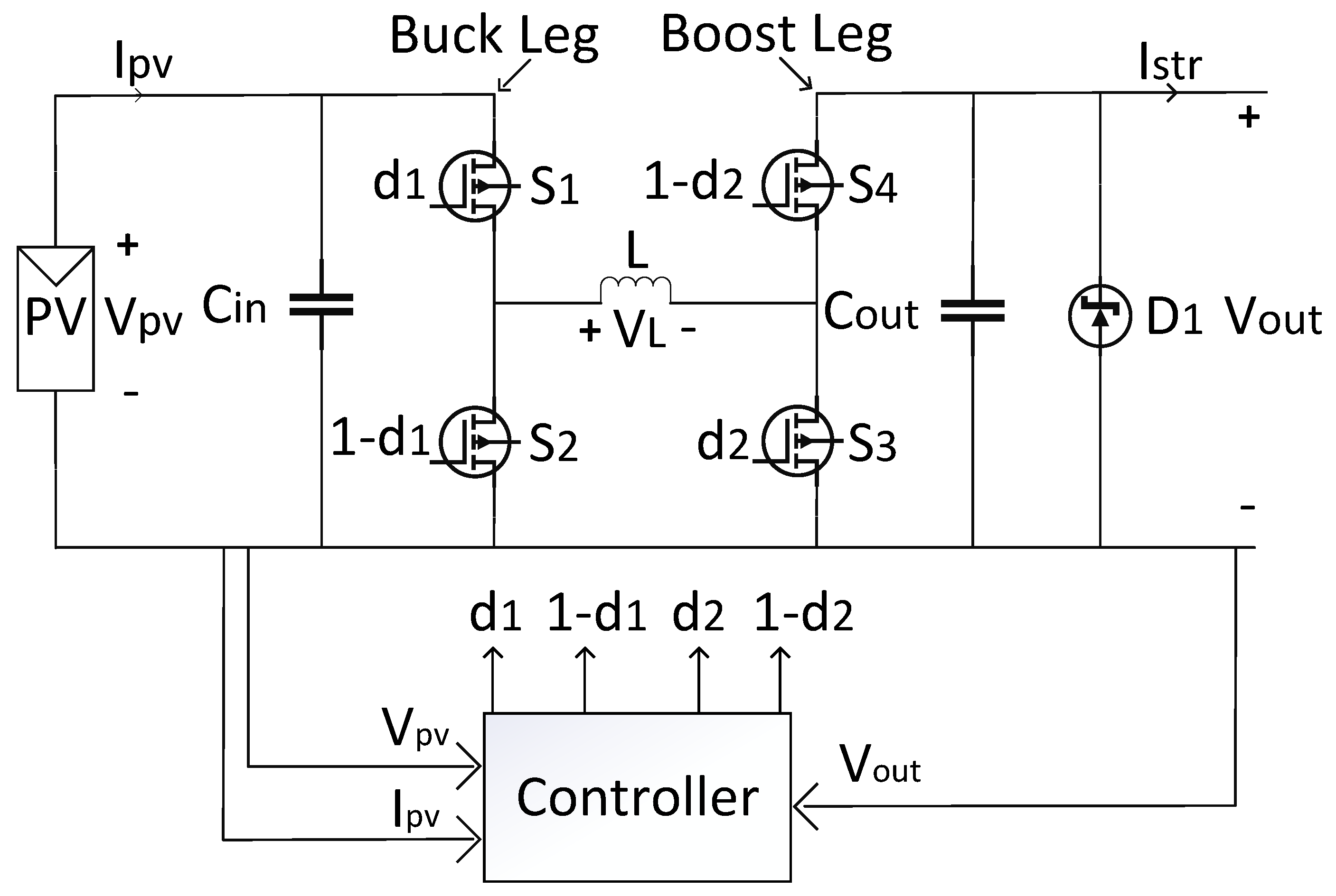
A flexible topology utilized for a series-connected micro-converter is the four-switch buck–boost converter in
Figure 2, having three operation modes: buck, boost, and pass-through modes [
8,
19,
20,
21]. This topology is also known as non-inverting buck–boost converter or cascaded buck–boost converter [
22]; it can work with high efficiency over a wide range of input and output voltages, even when these two voltages are approximately equal, by means of implementing a pass-through mode [
19,
21,
23]. Further evolved converter topologies capable of high-gain buck and boost operation can be found in the recent literature, e.g., [
24,
25]. Nonetheless, the improved functionality of such converters comes at the expense of a more involved design, control and greater component count. Hence, the four-switch buck–boost converter remains a favorite for the solar application, striking a balance between flexibility, complexity, and cost.
In the configuration of
Figure 1, all micro-converters share the same output current, namely string current,
. In the case of failure of any of the series-connected micro-converters, this string current flows through the micro-converter by-pass diode, indicated as
in
Figure 2.
The three operating modes (buck, boost, and pass through) for the converter in
Figure 2 are reported in
Table 1, where d
1 and d
2 are the buck and boost leg PWM duty cycles (0–100%), respectively [
21,
23,
26]. The additional mode named “initial state” refers to the micro-converter having its low-side switches permanently closed and high-side switches permanently open, blocking any flow of energy from the input to the output. The initial state is used before system start-up, when the solar irradiation is not high enough to transfer power to the grid, like in the early morning, or evening. The simultaneous buck–boost mode of the non-inverting buck–boost converter is omitted from
Table 1, as it is rarely used due to its high switching loss and low system efficiency [
14], compared to the pass-through mode [
21].
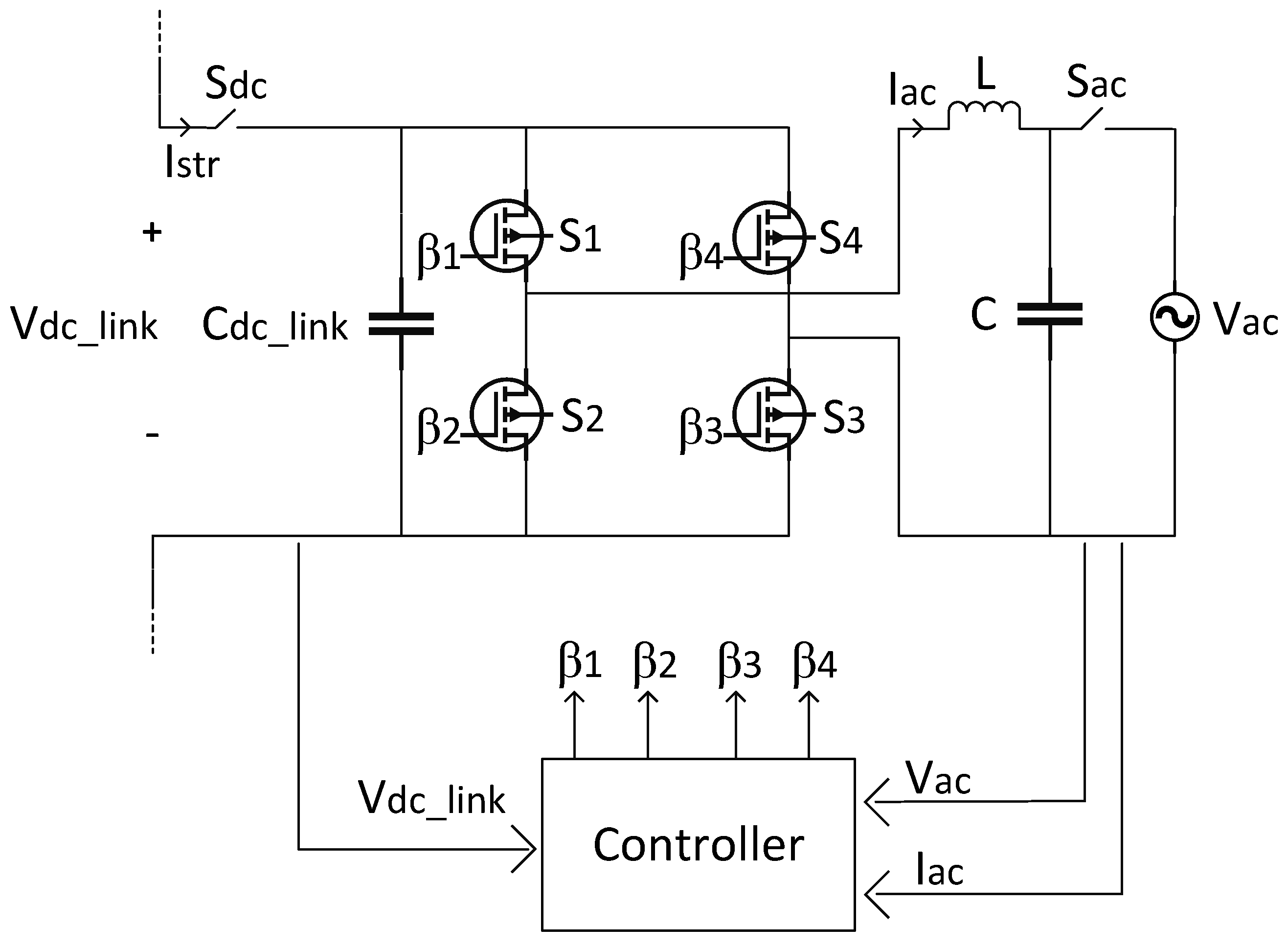
The string inverter for grid-tied connection is shown in
Figure 3. When each PV module is coupled to a micro-converter, the dc-link voltage of the grid-tied inverter is regulated to a fixed value to increase the efficiency and reduce the cost of the inverter [
9,
19,
27]. The inverter is connected to the grid via an LC filter, with the scope of filtering current harmonics.
3. Proposed Control Strategy
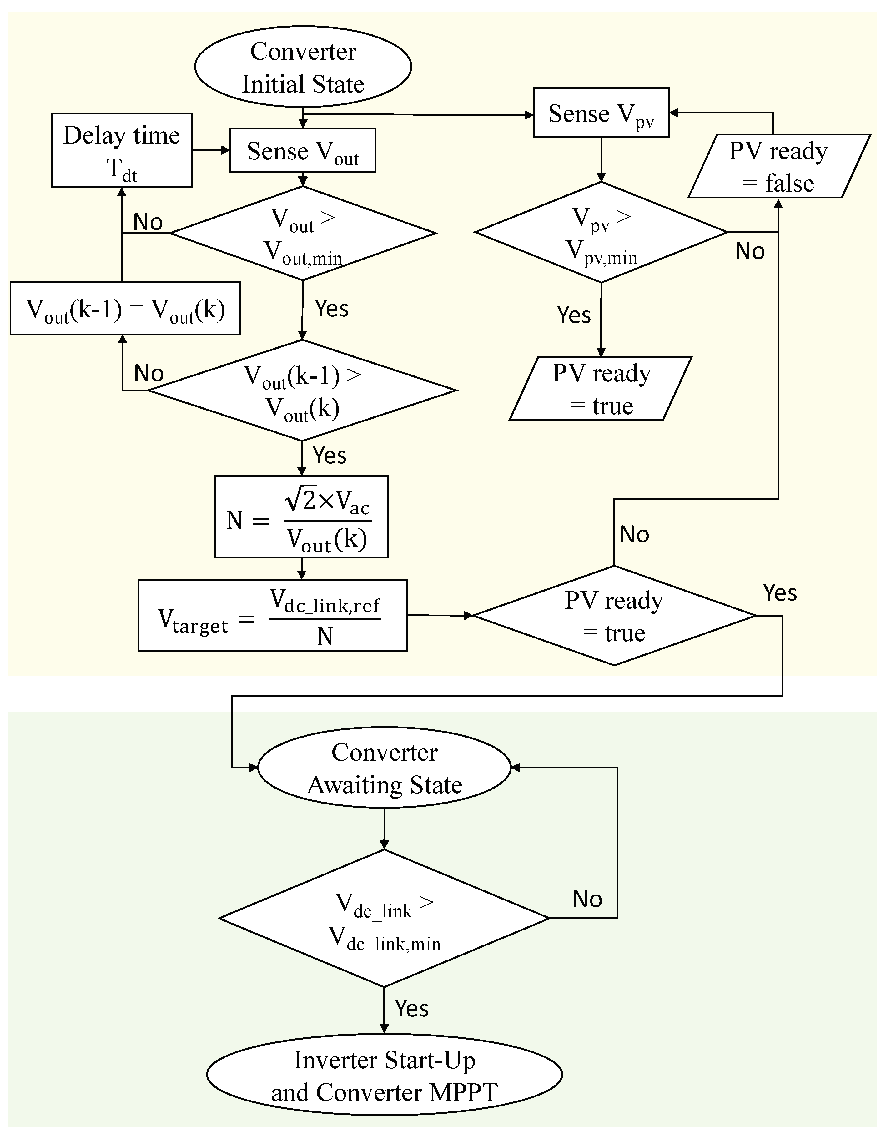
The flowchart of the proposed start-up procedure is displayed in
Figure 4. It consists of two sections. The top section (on yellow background) relates to the micro-converters, sensing their input and output voltage to establish if the associated PV module is receiving enough solar irradiation, and to calculate the output voltage target based on the number of micro-converters in the system. The bottom section (on green background) refers to the state where the micro-converters are transferring power to the dc-link, increasing its voltage up to the fixed reference required by the inverter to transfer power to the grid. The operations occurring in the flowchart of
Figure 4 are now explained in more detail.
Before the micro-converters’ start-up, all switches of the inverter are turned off, the inverter works as a rectifier and charges the dc-link capacitor to the peak value of the grid voltage. The dc-link voltage obtained is approximately equal to the peak value of the grid voltage and is distributed evenly across all micro-converters’ output stage [
14]. In the meantime, each micro-converter has its high-side switches turned off and low-side switches turned on (i.e., it is in the initial state, as per the first row of
Table 1), so that the PV modules are effectively disconnected from the converter outputs and the inverter dc-link.
With reference to the top of the flowchart in
Figure 4 (on yellow background), when the PV module starts to receive solar irradiance, finally increasing its voltage over a minimum threshold (i.e.,
is true), the corresponding micro-converter turns on in boost mode, transferring power to the common dc-link capacitor. From here on, each micro-converter stays in the so-called “converter awaiting state” shown in the lower half of
Figure 4 (on green background). In this state, each micro-converter operates in open-loop, with a PWM duty cycle set by the ratio between the target output voltage and measured PV module voltage. Note that variations in the micro-converter output voltage occur much more slowly than variations in the PV module voltage, given that the rate of change of a micro-converter output voltage is associated with the charge and discharge of the dc-link capacitor, whose value is much higher than a micro-converter input capacitance. This means that the micro-converter output voltage can be considered approximately constant, while the PV input voltage varies according to the set PWM duty cycle.
When enough micro-converters enter the “converter awaiting state” and the common dc-link capacitor voltage increases above the minimum value required by the grid-tied inverter (i.e., is true), the control of the inverter finally turns on, and regulates the dc-link voltage to a constant value () while injecting the current in the ac grid.
Compared to the number of sensors used in [
14], in the proposed algorithm, the micro-converter output current sensor and inverter dc-link current sensor are not utilized, which means that the micro-converter and inverter cost will be reduced overall. Furthermore, note that a micro-converter transfers power to the dc-link while in the “converter awaiting state”, which is entered only if the grid is present and a micro-converter senses an initial output voltage which is a fraction of the rectified grid voltage. Therefore, if the grid is not present, a micro-converter will not start processing power. This feature provides enhanced safety, compared to [
16], wherein it is proposed to form the inverter dc-link voltage by transferring PV power from the micro-converters.
4. Simulation Results
A simulation to validate the proposed start-up control technique was implemented by using the PLECS
® software (ver. 4.4), reflecting the setup of
Figure 1, with the main parameters reported in
Table 2. The PV modules were implemented using 3-dimensional lookup tables, allowing to accurately model the PV behavior for varying solar irradiation and temperature [
28,
29]. The results achieved are shown in
Figure 5,
Figure 6,
Figure 7,
Figure 8,
Figure 9 and
Figure 10, and discussed in the following.
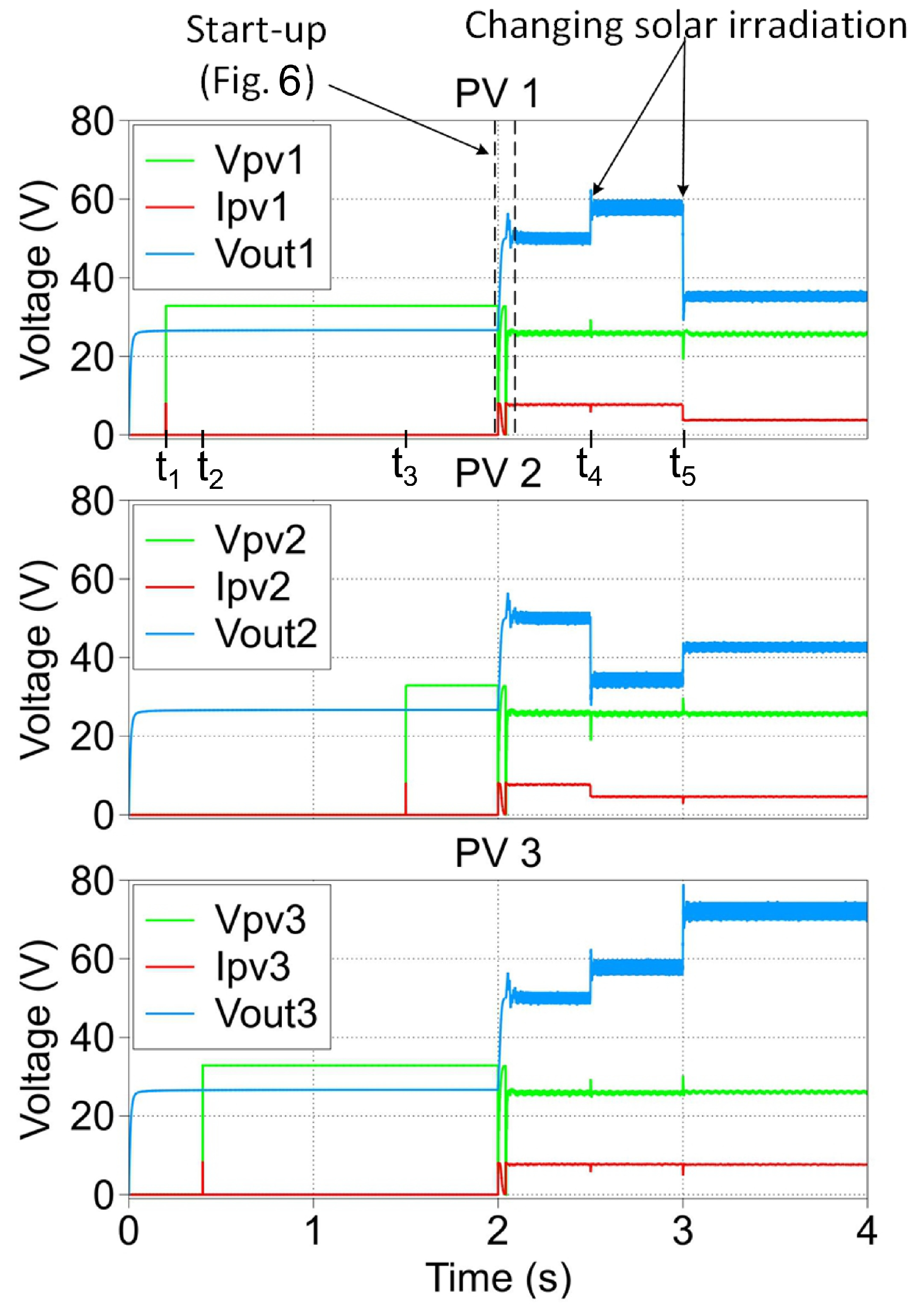
Figure 5 displays the behavior of PV voltage and PV current on each micro-converter during system start-up, and during changing solar irradiation. In this figure,
,
and
are the PV module starting times. The micro-converter start-up transient occurring between
and
is covered in detail later, and after it is completed, the inverter works with a constant dc-link voltage, i.e.,
. Prior to
, the solar irradiation is uniform and equal to per-mode=symbol 1
/
in each PV module; hence, the micro-converters’ output voltages assume the same value of approximately 50
(in Equation (
2),
, and each converter provides one third of the dc-link voltage). At
, the solar irradiation on the PV module of micro-converter 2 drops by 40%, with
, and
. As a result, the output voltage of micro-converter 2 decreases to
, while the output voltage of micro-converters 1 and 3, connected to the fully irradiated modules, raises to
. Finally, at
, the solar irradiation on the PV module connected to micro-converter 1 also drops by 50%, and it is
and
, with
being the power processed by the micro-converter connected to the fully irradiated PV module. With each PV module receiving a different solar irradiation, the output voltage of each micro-converter is different and
,
and
. These different output voltages add up to the value of the dc-link voltage and vary according to Equation (
2).
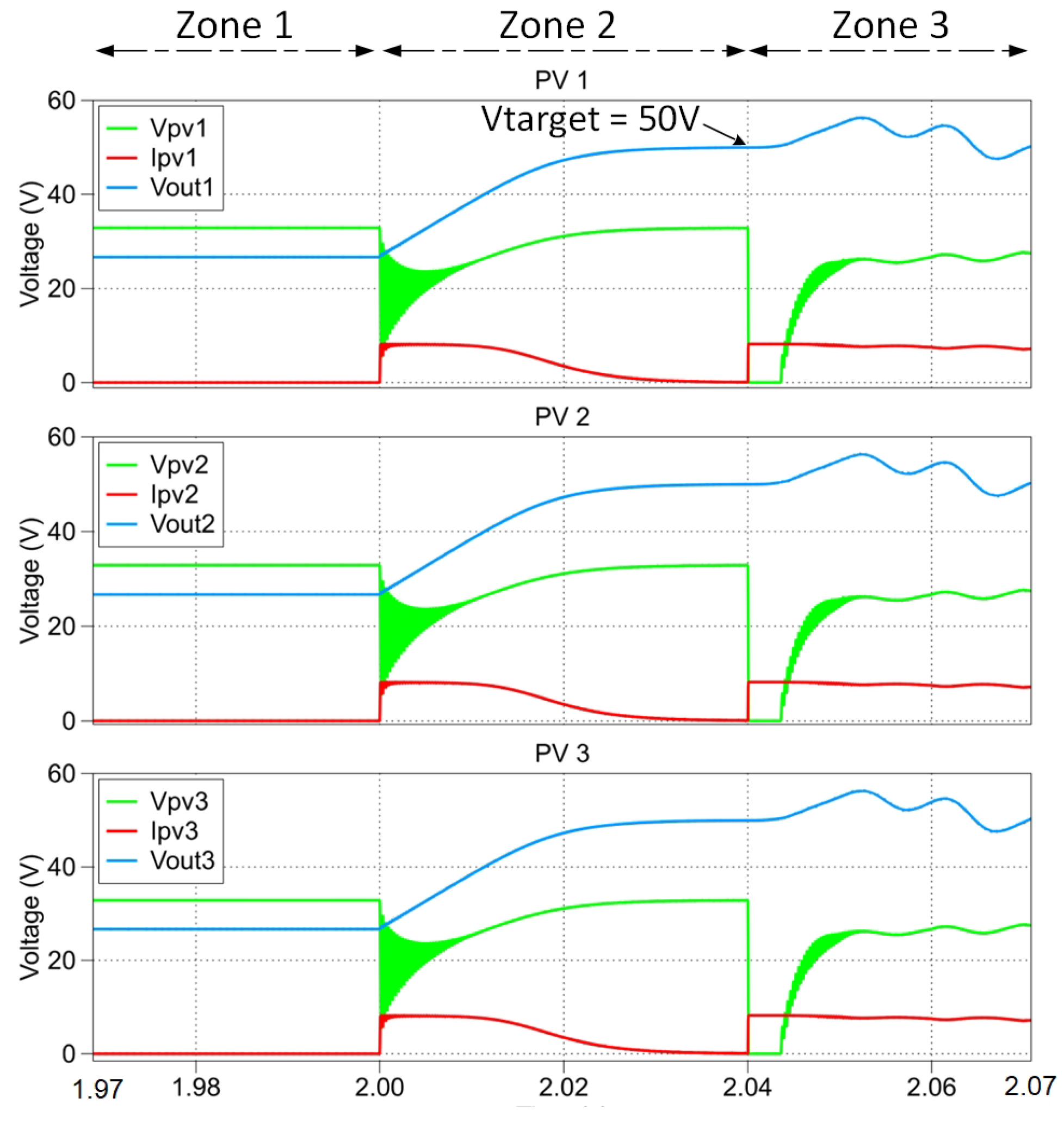
Figure 6 shows the magnified waveforms of each PV module voltage and current, and the output voltage of the micro-converters between 1.97 s and
, which is the portion of time in
Figure 5 when the micro-converter start-up routine of
Figure 4 takes place.
The behavior visible in
Figure 6 is divided into three main zones:
Zone 1 (0–2 s): micro-converter switches in the initial state. The switches of the micro-converters are in the initial state (cf.
Table 1), and all four switches of the grid-tied inverter are turned off, allowing the PV module’s current to stay at 0
and the PV module’s voltage to remain
, which is the open circuit voltage of the PV module. During this time, the dc-link capacitor is charged by the grid via the inverter operating in rectifier mode.
Zone 2 (2–2.04 s): micro-converter output voltage raises to the target value. Initially, the current delivered by the PV modules is increased to a value close to the short-circuit current, and it decreases slowly as the micro-converters’ output voltage approaches the target value of 50 (that is, ). In other words, during this time, the micro-converters raise the dc-link voltage from the peak ac voltage to the reference value, which is then regulated by the inverter when transferring power to the grid. In this portion of time, the micro-converters work in open-loop, with the PWM duty cycle derived from the target output voltage and the measured PV input voltage. The PV power processed by the micro-converters is used to increase the dc-link voltage and is not yet transferred to the grid.
Zone 3 (after
): inverter starts delivering power to the grid. After the output capacitor voltage of each micro-converter has reached the target value of 50 , each micro-converter starts working with the closed-loop control of their input voltage to track the reference calculated by the MPPT algorithm, which is embedded in each micro-converter’s controller. At the same time, the grid-tied inverter changes its operation from the naturally commutated rectifier mode to the controlled inverter mode, transferring to the grid the PV power processed by the micro-converters. Next, additional simulation results, including variables of the inverter dc and ac sides, are presented.
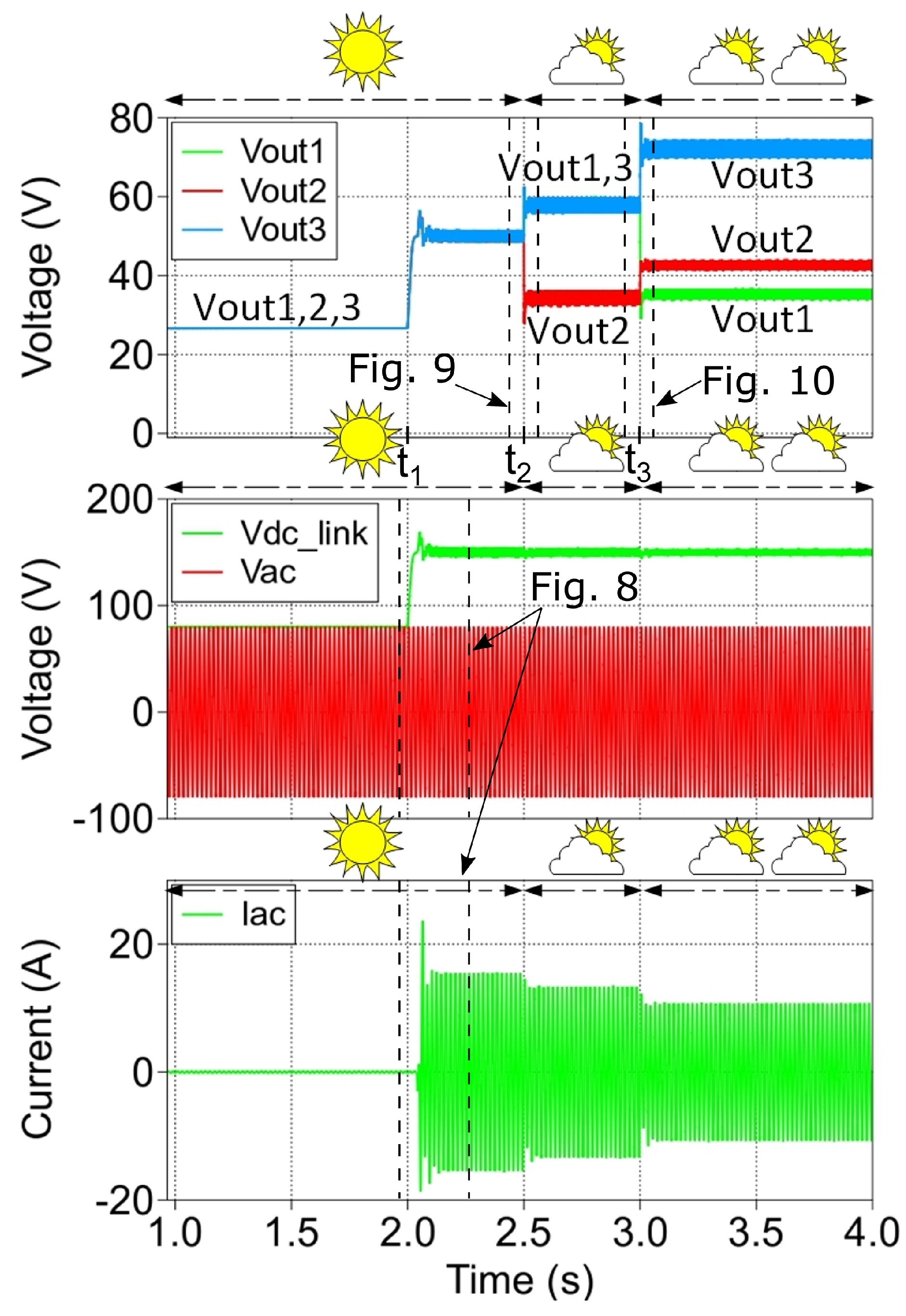
Figure 7 shows the waveforms of the micro-converters’ output voltage (top plot), inverter dc-link and grid voltage (middle plot), and grid current (bottom plot), during the start-up phase and during the changing solar irradiance. Prior to
, the dc-link voltage is formed by the rectified grid voltage since the inverter is used as a rectifier to charge the dc-link, as is visible in the middle plot. In turn, the output voltage of each micro-converter is one third of the peak ac voltage (
). Immediately after
and before
, after the start-up process is completed, the dc-link voltage reaches the reference value of 150
(middle plot), and each micro-converter output stage shares this value in an equal fraction,
(with k = 1, 2, 3) as visible in the middle plot. The start-up transient of the grid current injected by the inverter is displayed in the bottom plot. At
, the solar irradiation on PV module 2 drops by 40%, and at
, the solar irradiation on PV module 1 drops by 60%, causing self re-balancing of the micro-converter output voltages, where the greater output voltage associates with the PV module receiving the higher solar irradiance. From the middle plot, it is worth reporting that the dc-link voltage remains regulated and is unaffected by the changes in solar irradiation and power processed by the micro-converters. The current injected into the grid by the inverter in the bottom plot reduces as the irradiance drops on one or more modules, without displaying abrupt transients.
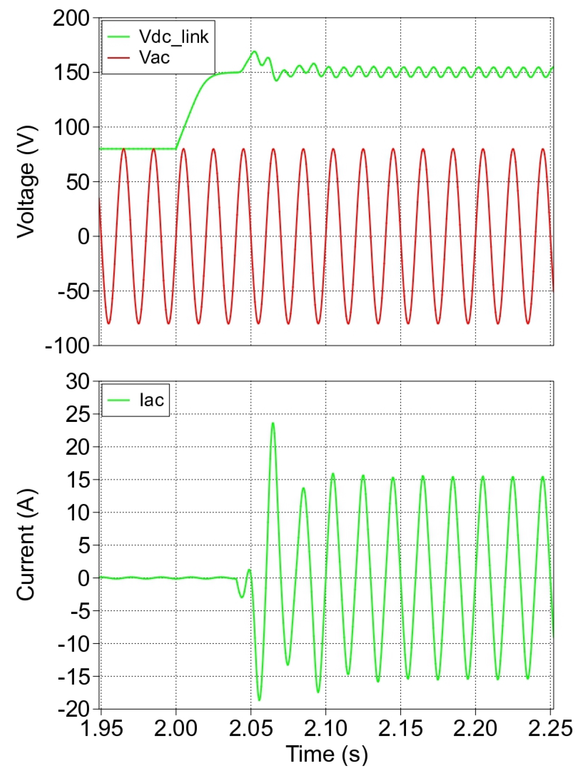
Figure 8 shows the zoomed-in portion of start-up transient for the dc-link voltage, grid voltage, and grid current. The dc-link voltage increases to the reference value
after all micro-converters are started up successfully. In addition, the sinusoidal grid current rapidly settles after a modest oscillation, indicating that the grid-tied inverter operates smoothly to transfer the PV power to the grid stably.
Figure 9 shows the waveforms of the micro-converters’ output voltage (top plot), inverter dc-link voltage and grid voltage (middle plot), and grid current (bottom plot) around the time when solar irradiation on PV module 2 drops (
in
Figure 7). It is apparent that the dc-link voltage is not affected by this transient, while the grid current smoothly and rapidly settles to its new reduced value. These waveforms indicate again that the system operates as intended, according to Equation (
2), and without abrupt transients.
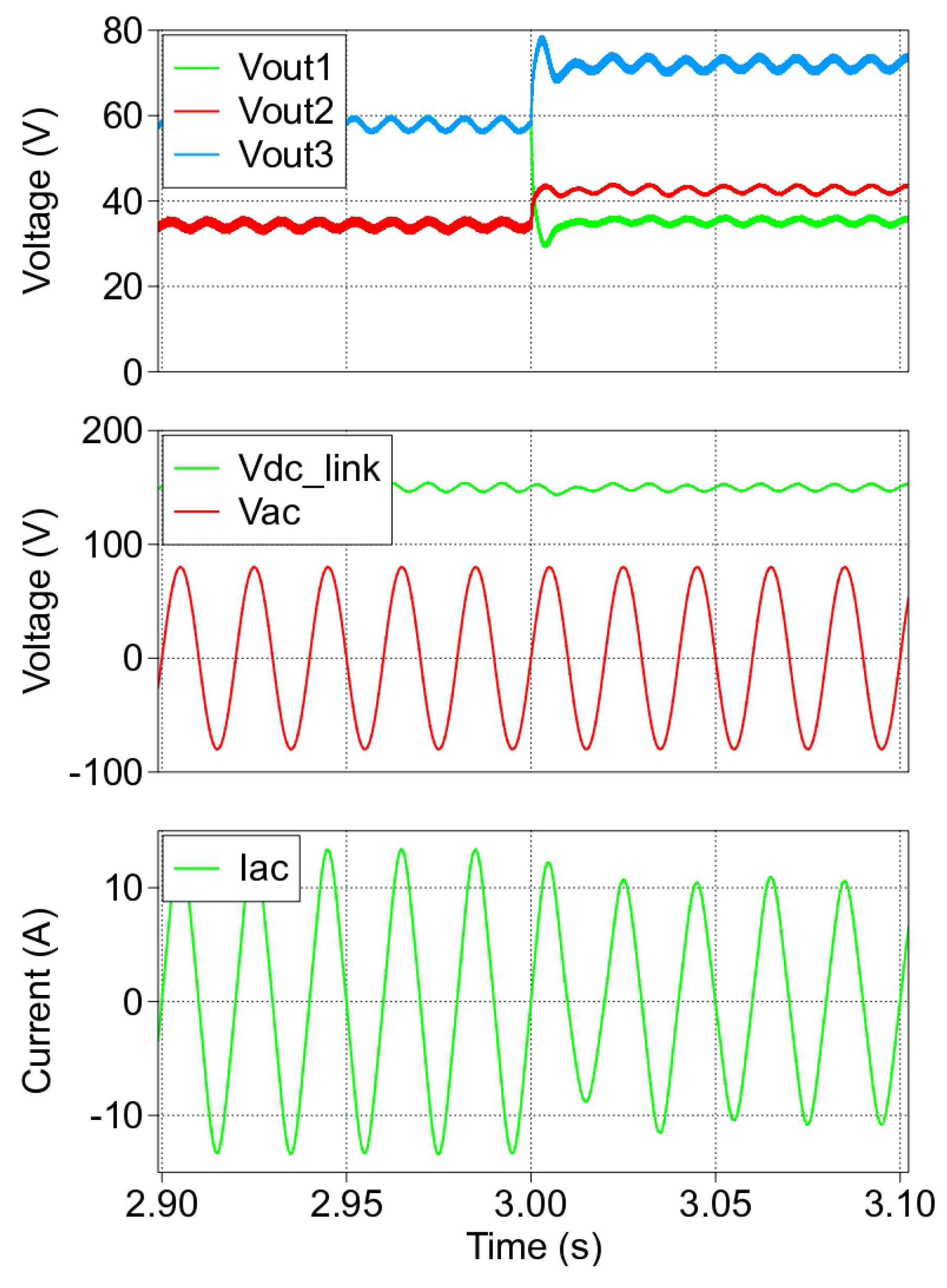
Finally,
Figure 10 displays the waveforms of the system during the portion of time (about
in
Figure 7) when the solar irradiation drops in a second PV module (PV module 1), further demonstrating that each micro-converters’ output voltage varies accordingly to the PV power (solar irradiation) at its own input. Here, the output voltage on the micro-converter connected to the PV module receiving the least solar irradiation is the lowest, while the output voltage of the micro-converter connected to the unshaded PV module is the highest. The inverter dc-link voltage remains unaffected by this transient.
The response time of each micro-converter is fast enough to allow the grid current to quickly reach its new steady-state condition in roughly 40 , limiting any negative impact on the public grid and ensuring the power quality of the distributed energy resources.
5. Discussion
The results presented in the previous section demonstrate the successful start-up of the grid-tied PV system equipped with micro-converters, and several points are worthy of note. The procedure starts from the ac grid charging the inverter dc-link capacitor; therefore, an equal portion of the rectified ac grid voltage appears at the micro-converter output stages, equal to , where N is the number of micro-converters. This initial output voltage value is effectively used as the information confirming to each micro-converter that the grid is present. If this voltage is lower than a set-threshold, it would indicate that the grid is either not present or faulty, and the micro-converters would halt their start-up procedure. The number of micro-converters, N, is not known a priori since it is dependent on the PV installation, and must be set up in the micro-converter at the deployment stage. In this way, each micro-converter will then calculate the minimum value of output voltage, , to start-up.
Another remark concerns the transition time when the processed PV power goes from charging the dc-link capacitor to being transferred to the grid. This transition is shown in
Figure 6,
Figure 7 and
Figure 8, and it occurs with minimal overshoot of the dc-link voltage and grid current. This proves that the control hierarchy of
Figure 4 helps the system to achieve a seamless start-up, where the PV power delivered to the grid transitions from zero to full, without adverse impacts on any voltage and current observed.
In the results displayed in the previous section, step changes in the solar irradiance were applied to test the response of the system, and to confirm the output voltage distribution across the micro-converters. The micro-converters’ output voltages changed according to the expectations from the theory, cf. Equation (
2), without implications on the system operation and stability. The step tests constitute a worst-case scenario of rapidly changing irradiance, which is unlikely to occur in practice, yet they are useful to assess the behavior of the system under extreme conditions.
Lastly, these results enrich the rather scarce literature existing on this topic. To the best of the authors’ knowledge, only three references discuss the problem of starting-up a PV system with micro-converters without communication. The most recent is [
18], which, however, deals with a system where the dc-link is not connected to a grid-tied inverter but to a resistive load instead. This reduces the complexity of the problem, making the devised solution not directly comparable with the one here articulated. As iterated in
Section 1, in the past, Refs. [
14,
16] proposed and tested smooth start-up techniques for systems configured like the one in this paper. Nonetheless, it is difficult to reproduce exactly the techniques put forward in these references for a direct comparison with the algorithm here described, as they are subject to interpretation. Concluding this discussion, it is apparent that this topic has not received the much needed attention from the academic community, and the purpose of this paper is to revitalize the discussion around it.


